JP2010500505A - Quick coupling connector - Google Patents
Quick coupling connector Download PDFInfo
- Publication number
- JP2010500505A JP2010500505A JP2009524219A JP2009524219A JP2010500505A JP 2010500505 A JP2010500505 A JP 2010500505A JP 2009524219 A JP2009524219 A JP 2009524219A JP 2009524219 A JP2009524219 A JP 2009524219A JP 2010500505 A JP2010500505 A JP 2010500505A
- Authority
- JP
- Japan
- Prior art keywords
- bore
- joint
- quick coupling
- injector
- tabs
- Prior art date
- Legal status (The legal status is an assumption and is not a legal conclusion. Google has not performed a legal analysis and makes no representation as to the accuracy of the status listed.)
- Ceased
Links
Images


Classifications
-
- F—MECHANICAL ENGINEERING; LIGHTING; HEATING; WEAPONS; BLASTING
- F02—COMBUSTION ENGINES; HOT-GAS OR COMBUSTION-PRODUCT ENGINE PLANTS
- F02M—SUPPLYING COMBUSTION ENGINES IN GENERAL WITH COMBUSTIBLE MIXTURES OR CONSTITUENTS THEREOF
- F02M55/00—Fuel-injection apparatus characterised by their fuel conduits or their venting means; Arrangements of conduits between fuel tank and pump F02M37/00
- F02M55/002—Arrangement of leakage or drain conduits in or from injectors
-
- F—MECHANICAL ENGINEERING; LIGHTING; HEATING; WEAPONS; BLASTING
- F02—COMBUSTION ENGINES; HOT-GAS OR COMBUSTION-PRODUCT ENGINE PLANTS
- F02M—SUPPLYING COMBUSTION ENGINES IN GENERAL WITH COMBUSTIBLE MIXTURES OR CONSTITUENTS THEREOF
- F02M55/00—Fuel-injection apparatus characterised by their fuel conduits or their venting means; Arrangements of conduits between fuel tank and pump F02M37/00
- F02M55/004—Joints; Sealings
-
- F—MECHANICAL ENGINEERING; LIGHTING; HEATING; WEAPONS; BLASTING
- F16—ENGINEERING ELEMENTS AND UNITS; GENERAL MEASURES FOR PRODUCING AND MAINTAINING EFFECTIVE FUNCTIONING OF MACHINES OR INSTALLATIONS; THERMAL INSULATION IN GENERAL
- F16L—PIPES; JOINTS OR FITTINGS FOR PIPES; SUPPORTS FOR PIPES, CABLES OR PROTECTIVE TUBING; MEANS FOR THERMAL INSULATION IN GENERAL
- F16L37/00—Couplings of the quick-acting type
- F16L37/008—Couplings of the quick-acting type for branching pipes; for joining pipes to walls
-
- F—MECHANICAL ENGINEERING; LIGHTING; HEATING; WEAPONS; BLASTING
- F16—ENGINEERING ELEMENTS AND UNITS; GENERAL MEASURES FOR PRODUCING AND MAINTAINING EFFECTIVE FUNCTIONING OF MACHINES OR INSTALLATIONS; THERMAL INSULATION IN GENERAL
- F16L—PIPES; JOINTS OR FITTINGS FOR PIPES; SUPPORTS FOR PIPES, CABLES OR PROTECTIVE TUBING; MEANS FOR THERMAL INSULATION IN GENERAL
- F16L41/00—Branching pipes; Joining pipes to walls
- F16L41/08—Joining pipes to walls or pipes, the joined pipe axis being perpendicular to the plane of the wall or to the axis of another pipe
- F16L41/12—Joining pipes to walls or pipes, the joined pipe axis being perpendicular to the plane of the wall or to the axis of another pipe using attaching means embracing the pipe
Abstract
Description
本発明は、急速連結継手(quick connection union)に関し、特に、内燃機関、特にディーゼルエンジンに供給する複数のインゼクタを含む燃料供給システムにおいて用いられる継手に関する。 The present invention relates to a quick connection joint, and more particularly, to a joint used in a fuel supply system including a plurality of injectors for feeding an internal combustion engine, particularly a diesel engine.
この種類の継手は、各インゼクタと関連付けられ、燃料タンクへの燃料の帰り(return)のための管にインゼクタを連結する機能を有する。インゼクタは、高圧ポンプを用いて供給され、燃料の帰りは、実際のところ比較的多量である。急速連結継手の燃料インゼクタへの使用は、それ自体周知であり、より詳細な説明は行わない。 This type of coupling is associated with each injector and has the function of connecting the injector to a tube for fuel return to the fuel tank. The injector is supplied using a high pressure pump and the return of fuel is actually relatively large. The use of quick connect joints in fuel injectors is well known per se and will not be described in more detail.
しかし、そのような急速連結継手のいくつかの種類は公知であり、それらはすべて、燃料帰り管との連結のための手段と、帰り燃料の出口を形成するためにインゼクタ内に形成されたボアへと導入され得る管状ノズルと、このボア内に該ノズルを保持するための手段とを提供される。 However, several types of such quick connect joints are known and they all have means for connection to the fuel return pipe and a bore formed in the injector to form the return fuel outlet. A tubular nozzle is provided that can be introduced into the bore and means for retaining the nozzle within the bore.
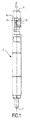
図1から図5は、インゼクタ2を帰り管(図示されない)に連結するために、現在用いられるそのような急速連結継手1の構造および使用を示している。インゼクタ2は、その端部の1つにおいて、高圧の燃料のための噴射ノズル3と、別の端部において、軸方向の取り入れ口4とを含む。
FIGS. 1-5 illustrate the construction and use of such a quick connect joint 1 currently used to connect the
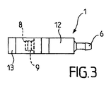
図3および図4は、急速連結継手1を側面から見た図と、上から見た図をそれぞれ示す。 3 and 4 show a view of the quick coupling joint 1 as viewed from the side and a view as viewed from above, respectively.
継手1は、燃料帰り管(図に示されない)への、後方の端部における連結手段6、7を有する円筒形の中空の本体部5を含んでいる。
The joint 1 includes a cylindrical
前方の端部において、継手1は、Oリングシール9の形態のシーリング手段を支持する管状ノズル8を含む。この管状ノズル8は、インゼクタの内側と連絡して帰り燃料を受容するために、インゼクタ2内のボア10において受容され得、ボアの底部で筐体11内に静置する。
At the forward end, the joint 1 includes a tubular nozzle 8 that supports sealing means in the form of an O-
継手1の本体部5は、筐体11内に管状ノズル8を保持するための手段を支持する。これらの保持手段は、フレーム12の前方への延長を形作る2つの弾性のあるアーム13を携えるフレーム12を含む。
The
フレーム12は、概して長方形であり、後方の端部で連結手段6、7を、前方の端部でノズル8を把持する。ノズル8を把持するフレーム12の側面は、インゼクタ2の外の表面に適合する湾曲した形状を有することにより、ノズルがボア10に挿入されるときに、インゼクタ2に接して押し付けられる。
The
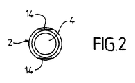
2つの弾性のあるアーム13は、互いに実質的に平行にノズル8のどちらの側面上にも延在することにより、ノズル8がボア10へと導入されるときに、インゼクタ2にスナップオン(snap onto)する。インゼクタ2上のアーム13の把持を改善するために、インゼクタ2は、その周囲にアームが接して静置し得る互いに平行の2つの平坦部14を有し、アームの端部が互いの方に曲げられることにより、インゼクタの外の面に接して支え、従ってインゼクタに接する位置において継手を保持する。
The two
しかし、これまで記載されてきた急速連結継手1は、その使用において非常に制限される。なぜならば、ボア10がインゼクタ2の軸と直角であり、アーム13が通過してスナップオンすることを可能にするために、継手1の背後に十分な空間が存在することを前提とするからである。
However, the quick coupling joint 1 described so far is very limited in its use. This is because it is assumed that the
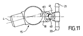
換言すると、図11および図12に示される角度α1およびα2によって例示されるような特定の角度の継手を同時に1つ以上の平面に置くことを必要とするとき(例えばエンジン環境のため)に、この継手の使用は不可能である。燃料取り入れ口がインゼクタの軸に関して半径方向であるときに、特に斜めに継手を置く必要が起こる。 In other words, when it is necessary to place joints of a particular angle, such as illustrated by the angles α1 and α2 shown in FIGS. 11 and 12, on one or more planes simultaneously (eg for engine environments) Use of this joint is not possible. When the fuel intake is in the radial direction with respect to the injector axis, it is necessary to place the joint in particular at an angle.
他の急速連結継手もまた公知であり、それらの継手は、継手をインゼクタ上に保持するための手段としてクリップを利用し、その第1の分岐が、継手のノズルの溝部内に収納されるためにボア内に導入される。一方で、その端部において捕捉手段を有するその第2の分岐が、従ってクリップを適所に保持するために空洞に差し込まれ、一方で、その摘出がノズルを解放することを可能にする。しかし、この解決策は、その実装において比較的複雑である。なぜならば、その解決策が多くの高精度の機械加工を必要とするからである。 Other quick-connect couplings are also known, since these couplings utilize a clip as a means for holding the coupling on the injector, and its first branch is housed in the groove of the coupling nozzle. Is introduced into the bore. On the one hand, the second branch with capture means at its end is therefore inserted into the cavity to hold the clip in place, while its extraction allows the nozzle to be released. However, this solution is relatively complex in its implementation. This is because the solution requires a lot of high precision machining.
本発明の目的は、インゼクタの軸に実質的に任意の角度で装着され得、製造が簡単であり、容易に装着され、かつ取り外され得る急速連結継手を提案することである。さらに、一実施形態に従うと、この継手は、保持手段の時ならぬ解放によって引き起こされる燃料のいかなる漏れをも防止する二重の安全確保を含んでいる。 It is an object of the present invention to propose a quick coupling joint that can be mounted on the injector shaft at virtually any angle, is simple to manufacture, can be easily mounted and removed. In addition, according to one embodiment, the coupling includes a double safety feature that prevents any leakage of fuel caused by an unexpected release of the retaining means.
本発明の目的は、内燃機関のインゼクタを燃料帰り管に連結し得る急速連結継手である。該継手は、概して円筒形の中空の本体部を含み、後方の端部で該燃料帰り管に連結するための手段を提示し、前方の端部でシーリング手段を支持する管状ノズルが提示されて、該インゼクタの内側と連絡するように該インゼクタの周囲のボア内に形成された筐体において受容されることを可能にする。該筐体において該管状ノズルを保持するための手段を支持する該本体部は、該保持手段が2つの弾性のあるタブを該本体部の軸と実質的に同心円状に該本体部の周囲に延在する円弧内に含み、該タブのそれぞれは、1つの側面が開いている、円弧内のスロットを該本体部の周囲と画定することによって特徴付けられ、また、該タブが、該インゼクタの該ボアの内側に提供された溝部と協働し得ることによって特徴付けられる。 An object of the present invention is a quick coupling joint that can connect an injector of an internal combustion engine to a fuel return pipe. The joint includes a generally cylindrical hollow body, presenting means for connecting to the fuel return pipe at a rear end and presenting a tubular nozzle supporting a sealing means at the front end. Allowing it to be received in a housing formed in a bore around the injector to communicate with the inside of the injector. The body supporting the means for holding the tubular nozzle in the housing has a holding means having two elastic tabs around the body substantially concentrically with the axis of the body. Each of the tabs is characterized by defining a slot in the arc that is open on one side with the periphery of the body portion, the tabs including Characterized by being able to cooperate with a groove provided inside the bore.
本発明のさらなる特徴に従うと、
−該タブは、自由端部において、該溝部に差し込むことが可能な突起部の形態の捕捉部材(organ)を携える。
−各タブの固定端部は、該本体部上の半径方向のフランジによって該本体部と接合される。
−第1のタブの該半径方向のフランジは、第2のタブのフランジの真向かい側に配置される。
−該突起部の厚さは、該スロットの厚さと実質的に一致する。
−該突起部は、外側がドーム状の形態を有する。
−該タブは、該ノズルが該ボアに挿入されるときに、該ボアからはみ出るように寸法が決められる。
−タブの前方への曲げは、該本体部の周囲のつば部(collar)によって限界を定められる。
−該つば部は、該ボアへの該ノズルの導入の際に、該ボア内の円環状の肩部に接して止め具として作動し得る。
−該本体部、該連結手段、該タブ、該フランジ、および該つば部は、一体となって作成される。
−該継手はまた、タブを係止するための挿入部材を含み、これらの係止部材は、円弧の形状を有し、該ボアへの該ノズルの導入に続いて、該スロットのそれぞれのスロットに挿入され得る。
−該係止部材は、該本体部上で滑動するように搭載されたリングの下方の面に接合される。
−該係止部材は、該スロットへの該係止部材の導入の際に、該フランジを受容し得る下方に開いた空洞を該係止部材の間で画定する。
−該リングは、弾性材料で作成され、該リングが該本体部上に側面から搭載されることを可能にするように割裂される。
−該係止部材は、該スロット内に、そして隣のタブまで延在する。
According to a further feature of the present invention,
The tab carries at its free end an organ in the form of a protrusion which can be inserted into the groove.
The fixed end of each tab is joined to the body by a radial flange on the body.
The radial flange of the first tab is arranged directly opposite the flange of the second tab.
The thickness of the protrusion is substantially equal to the thickness of the slot;
The protrusion has a dome-like configuration on the outside;
The tab is dimensioned to protrude from the bore when the nozzle is inserted into the bore;
-The forward bending of the tab is limited by a collar around the body.
The collar can act as a stop against the annular shoulder in the bore upon introduction of the nozzle into the bore;
The body part, the connecting means, the tab, the flange and the collar part are made in one piece;
The coupling also includes insertion members for locking the tabs, the locking members having an arcuate shape and following introduction of the nozzle into the bore, each slot of the slot; Can be inserted.
The locking member is joined to the lower surface of the ring mounted so as to slide on the body;
The locking member defines a downwardly open cavity between the locking members that can receive the flange upon introduction of the locking member into the slot;
The ring is made of an elastic material and is split to allow the ring to be mounted on the body from the side.
The locking member extends into the slot and to the next tab;
本発明はまた、上で規定された急速連結継手と関連し、上述の特徴を有する継手と関連付けられることと、継手上に提供される保持手段と協働することが適切であることとによって特徴付けられる。 The invention also relates to a quick coupling joint as defined above, characterized in that it is associated with a joint having the above-mentioned characteristics and that it is suitable to cooperate with holding means provided on the joint. Attached.
本発明の他の特徴および利点は、添付の図面への参照とともに、本発明の制限ではない実施形態の以下の説明から明らかになる。 Other features and advantages of the present invention will become apparent from the following description of non-limiting embodiments thereof, with reference to the accompanying drawings.
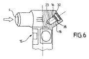
図6は、内燃機関に適合される種類のインゼクタ15の一部分を示す。このインゼクタ15は、高圧の燃料のための半径方向の取り入れ口4を有し、インゼクタ15は、図7および図8に示すような本発明に従う急速連結継手17を受容するために適切なボア16を提供される。ボア16は、インゼクタ15の後方の端部で管18内に形成されて、インゼクタ15の内側と連絡している。
FIG. 6 shows a part of an
示された実施例において、T継手である継手17は、概して円筒形の中空の本体部19を含み、後方の端部で連結手段20、21を提示することにより、継手の燃料帰り管(図示されない)への連結を可能にする。
In the embodiment shown, the joint 17, which is a T-joint, includes a generally cylindrical
前方の端部において、本体部19は、Oリングシール9の形態のシーリング手段を提供される管状ノズル22を提示する。ノズル22は、ボア16の底部で筐体23において受容され得る(図12を参照されたい)。
At the front end, the
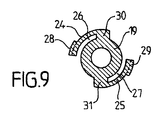
本体部19は、筐体23においてノズル22を保持するための手段を支持する。本発明に従うと、これらの保持手段は、2つの弾性のあるタブ24、25を、本体部の軸A−Aと実質的に同心円状に延在する円弧内に含んでいる。
The
弾性のあるタブ24、25のそれぞれは、円弧26、27内において1つのスロットを本体部19の周囲と画定し、その自由端部において、突起部28、29の形態の捕捉部材を携える。
Each of the
弾性のあるタブ24、25のそれぞれは、本体部19上の半径方向のフランジ30、31によって本体部19に接合されて、それぞれのタブを外側にオフセットすることにより、対応するスロット26、27の厚さは、突起部28、29の厚さと実質的に一致する。第1のタブ24のフランジ30は、第2のタブ25のフランジ31の真向かい側に配置される。
Each of the
突起部28、29は、ボア16の後方の部分に形成された溝部32に差し込むこと、継手17のノズル22のボア16への導入において、継手の本体部19に弾性的に引っ込むこと、そしてタブ24、25の弾性のある戻りによって溝部32に延在することが可能である。
The
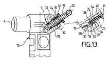
インゼクタ15の管18のボア16内へのタブ24、25の導入を容易にするために、突起部28、29は、有利に、ボア16の開口のまわりのエッジと接触するスロープを形成する傾斜した下方の表面33を有し、同様に、下方の表面33とよりよく協働するように同じ角度で傾斜した環状の表面34を含み得る。これらの詳細は、図13の一部分の拡大において最もよく示される。
In order to facilitate the introduction of the
インゼクタ15の管18のボア16からのタブ24、25の離脱を容易にするために、突起部28、29はまた、有利に、溝部32の上部に提供された同じ角度で傾斜した表面36との接触においてスロープを形成する傾斜した上方の表面35を有する。
To facilitate disengagement of the
図に示されない改変された実施形態に従うと、突起部28、29は、断面において事実上単に円の切片を提示し得、この場合に、傾斜した表面34および36は、もはや不可欠ではない。いずれにしろ、外側がドーム状の形態を提供することが、実際のところ必要となるだけである。
According to a modified embodiment not shown in the figure, the
継手17はまた、タブ24、25のすぐ後の本体部19の周囲に配置されたつば部37を含むことにより、ボア16からのノズル22の離脱における、これらタブの前方への曲げの限界を定める。
The joint 17 also includes a
つば部37はまた、ボア16における溝部32の下方の範囲を定める円環状の肩部38に接して迫台に入ることによって、止め具として作動する。肩部38に関してつば部37の位置は、ボア16への本体部29の導入の長さを決定する。
The
さらに、タブ24、25は、ノズルがボアにおけるその筐体23内にあるときに、継手17の除去の際のタブの半径方向の圧縮を可能にするために、ボア16からはみ出るように寸法が決められる。
Further, the
有利に、円筒形の本体部19、連結手段20、21、タブ24、25、フランジ30、31、およびつば部37は、一体となって、例えばポリアミドなどの弾性材料の射出成型によって作成される。
Advantageously, the
図に示された実施例において、継手17はまた、タブ24、25を係止するための挿入部材39、40を含む。これらの係止部材39、40は、円弧における形状を有し、継手17をインゼクタ15に連結するノズル22のボア16への導入の後、それぞれのスロット26、27に挿入され得る。この様態において、突起部28、29は、もはや溝部32から出られ得ず、タブは、従ってボア16内に係止される。
In the embodiment shown in the figure, the
係止部材39、40は、本体部19上で滑動するように搭載されたリング41の下方の面に有利に接合される。係止部材39、40は、それらの間で下方に開いたノッチ42、43を画定し、ノッチ42、43は、スロット26、27への係止部材の導入の際にフランジ30、31を受容し得る。好適には、係止部材は、1つのフランジ(30または31)から隣のフランジまで延在して、完全にスロット26、27をふさぐ。
The locking
従って、係止部材39、40は、一体となって弾性材料でも有利に作成されるフランジ付のスリーブの一般的な形態を有するアセンブリをリング41とともに形成する。このアセンブリを本体部19上に搭載するために、リングは、ノッチのうちの1つまで割裂される(44)。これは、該アセンブリが本体部19上に側面から搭載されることを可能にする。
Thus, the locking
急速連結継手17は、スロットから離脱した係止部材39、40を示す図7に示されたその状態から、インゼクタ15に装着することは特に簡単である。それから突起部28、29がボア16のエッジと接触するまで、継手のノズル22をボア16に導入し、次いで押すことだけが必要であり、それにより、タブ24、25は、従って半径方向の内側に弾性的に押し戻される。この導入の動きは、つば部37がボアの円環状の肩部38に接して迫台に入るまで続けられ、一方で同時に継手をこの位置に保持するために、突起部28、29が溝部32に収納されるようになる。
The quick coupling joint 17 is particularly easy to mount on the
同時に、タブ24、25は、図9に示された形態を再びとり、次いでボア16内のタブを完全に係止するために、リング41を押して係止部材39、40を下方へ外すことが可能であることにより、これらの部材がスロット26、27に入る。従って、係止部材39、40は、二重の安全確保を提供し、継手が故意でなく係合解除され得るリスクが全くない。
At the same time, the
継手17の取り外しもまた非常に簡単である。最初に、係止部材39、40は、リング41を引くことによって外側に外され、次いで、タブ24、25がボア16からはみ出ているので、それらは、突起部28、29をボアの溝部32から取り外すために指でつままれ得、それによって継手の全体が問題なく離脱される。
The removal of the joint 17 is also very simple. Initially, the locking
もちろん、多くの改変が、従って本発明の範囲を逸脱することなく当業者によってなされ得るので、本発明は、例示され、記載された実施形態に制限されない。 Of course, the present invention is not limited to the illustrated and described embodiments, as many modifications can thus be made by those skilled in the art without departing from the scope of the invention.
Claims (16)
概して円筒形の中空の本体部(19)を含み、
後方の端部で該燃料帰り管に連結するための手段(20、21)と、
前方の端部でシーリング手段(9)を支持する管状ノズル(22)であって、該インゼクタの内側と連絡するように該インゼクタ(15)の周囲のボア(16)内に形成された筐体(23)において受容されることが可能である、管状ノズル(22)と
を提供し、
該筐体(23)において該管状ノズル(22)を保持するための手段(24、25)を支持する該本体部(19)が、該保持手段(24、25)が2つの弾性のあるタブを該本体部の軸(A−A)と実質的に同心円状に該本体部(19)の周囲に延在する円弧内に含んでいることと、
該タブ(24、25)のそれぞれが、1つの側面が開いている、円弧内のスロット(26、27)を該本体部(19)の周囲と画定することと、
該タブ(24、25)が、該インゼクタ(15)の該ボア(16)の内側に提供された溝部(32)と協働することが可能であることと
を特徴とする、急速連結継手。 A quick coupling joint capable of connecting an injector (15) of an internal combustion engine to a fuel return pipe,
A generally cylindrical hollow body (19),
Means (20, 21) for coupling to the fuel return pipe at the rear end;
A tubular nozzle (22) supporting sealing means (9) at the front end, formed in a bore (16) around the injector (15) so as to communicate with the inside of the injector A tubular nozzle (22) that can be received in (23);
The body (19) supporting the means (24, 25) for holding the tubular nozzle (22) in the housing (23), the holding means (24, 25) being two elastic tabs In a circular arc extending around the body portion (19) substantially concentrically with the axis (AA) of the body portion;
Each of the tabs (24, 25) defining a slot (26, 27) in an arc, open on one side, with the periphery of the body (19);
A quick coupling joint, characterized in that the tabs (24, 25) can cooperate with a groove (32) provided inside the bore (16) of the injector (15).
Applications Claiming Priority (2)
| Application Number | Priority Date | Filing Date | Title |
|---|---|---|---|
| EP06291313A EP1890030B1 (en) | 2006-08-16 | 2006-08-16 | Quick connect coupling |
| PCT/FR2007/051810 WO2008020145A2 (en) | 2006-08-16 | 2007-08-10 | Quick-coupling connector |
Publications (2)
| Publication Number | Publication Date |
|---|---|
| JP2010500505A true JP2010500505A (en) | 2010-01-07 |
| JP2010500505A5 JP2010500505A5 (en) | 2011-08-04 |
Family
ID=37697979
Family Applications (1)
| Application Number | Title | Priority Date | Filing Date |
|---|---|---|---|
| JP2009524219A Ceased JP2010500505A (en) | 2006-08-16 | 2007-08-10 | Quick coupling connector |
Country Status (6)
| Country | Link |
|---|---|
| US (1) | US20110095522A1 (en) |
| EP (1) | EP1890030B1 (en) |
| JP (1) | JP2010500505A (en) |
| AT (1) | ATE408752T1 (en) |
| DE (1) | DE602006002823D1 (en) |
| WO (1) | WO2008020145A2 (en) |
Families Citing this family (6)
| Publication number | Priority date | Publication date | Assignee | Title |
|---|---|---|---|---|
| GB2467321A (en) * | 2009-01-28 | 2010-08-04 | Fluid Transfer Systems Ltd | Snap-fit connector and non-return valve for a fuel injector leak-off line |
| GB2469119B (en) * | 2009-04-03 | 2013-07-03 | Managed Pressure Operations | Drill pipe connector |
| DE102010022304A1 (en) * | 2010-06-01 | 2011-12-01 | Veritas Ag | Quick coupling for fluid lines |
| RU2461762C1 (en) * | 2011-07-27 | 2012-09-20 | Открытое акционерное общество "Центральное конструкторское бюро машиностроения" | Connection device |
| ITTO20120090A1 (en) * | 2012-02-03 | 2013-08-04 | Eltek Spa | DEVICE AND / OR DUCT FOR DETECTION OF FUEL SUPPLIED TO AN INTERNAL COMBUSTION ENGINE |
| EP4112914A1 (en) * | 2021-06-29 | 2023-01-04 | Volvo Truck Corporation | Fuel conduit connection assembly for a vehicle |
Citations (6)
| Publication number | Priority date | Publication date | Assignee | Title |
|---|---|---|---|---|
| US5437650A (en) * | 1993-03-23 | 1995-08-01 | Abbott Laboratories | Securing collar for cannula connector |
| DE19940387C1 (en) * | 1999-08-25 | 2001-02-22 | Siemens Ag | Leakage connection for connecting leakage line to fuel injector of internal combustion engine is cost-effective to produce and enables simple and reliable installation |
| JP2003028031A (en) * | 2001-07-16 | 2003-01-29 | Daihatsu Motor Co Ltd | Installation device for fuel injection valve in multicylinder internal combustion engine |
| US20040195831A1 (en) * | 2000-06-08 | 2004-10-07 | Hitachi Metals Ltd. | Sleeve-type pipe joint |
| JP2006153015A (en) * | 2004-11-25 | 2006-06-15 | Itt Mfg Enterp Inc | Device for attaching fuel return pipe to fuel injector, device for attaching return pipe to fuel injector and device for sucking fuel from fuel injector |
| JP2007332910A (en) * | 2006-06-16 | 2007-12-27 | Nissan Diesel Motor Co Ltd | Fuel supply system device |
Family Cites Families (10)
| Publication number | Priority date | Publication date | Assignee | Title |
|---|---|---|---|---|
| US3245703A (en) * | 1963-10-28 | 1966-04-12 | Robert S Manly | Quick detachable pipe coupling |
| US4875711A (en) * | 1988-04-25 | 1989-10-24 | Usui Kokusai Sangyo Kaisha Ltd. | Slender tube connector |
| DE9114365U1 (en) * | 1991-11-18 | 1992-03-12 | Vorschepoth, Heinrich, 5000 Koeln, De | |
| US6068303A (en) * | 1995-09-13 | 2000-05-30 | Hollnagle; Harold E. | Tube for connection to female socket |
| US5806898A (en) * | 1996-11-21 | 1998-09-15 | Hollnagle; Harold E. | Tube quick connect coupling |
| DE19755826C1 (en) * | 1997-12-16 | 1999-05-20 | Raymond A & Cie | Releasable connector for pressure hoses |
| DE20319558U1 (en) * | 2003-12-17 | 2005-04-28 | Voss Automotive Gmbh | Plug-in and lockable cable connector |
| DE202005015966U1 (en) * | 2005-10-10 | 2007-02-15 | Voss Automotive Gmbh | Connectors for media cables |
| JP4929864B2 (en) * | 2006-06-15 | 2012-05-09 | 株式会社デンソー | Piping joint device |
| US7658420B2 (en) * | 2006-07-13 | 2010-02-09 | Parker-Hannifin Corporation | Quick-connect fitting with unlocking ring |
-
2006
- 2006-08-16 DE DE602006002823T patent/DE602006002823D1/en active Active
- 2006-08-16 EP EP06291313A patent/EP1890030B1/en not_active Not-in-force
- 2006-08-16 AT AT06291313T patent/ATE408752T1/en not_active IP Right Cessation
-
2007
- 2007-08-10 WO PCT/FR2007/051810 patent/WO2008020145A2/en active Application Filing
- 2007-08-10 JP JP2009524219A patent/JP2010500505A/en not_active Ceased
- 2007-08-10 US US12/377,272 patent/US20110095522A1/en not_active Abandoned
Patent Citations (6)
| Publication number | Priority date | Publication date | Assignee | Title |
|---|---|---|---|---|
| US5437650A (en) * | 1993-03-23 | 1995-08-01 | Abbott Laboratories | Securing collar for cannula connector |
| DE19940387C1 (en) * | 1999-08-25 | 2001-02-22 | Siemens Ag | Leakage connection for connecting leakage line to fuel injector of internal combustion engine is cost-effective to produce and enables simple and reliable installation |
| US20040195831A1 (en) * | 2000-06-08 | 2004-10-07 | Hitachi Metals Ltd. | Sleeve-type pipe joint |
| JP2003028031A (en) * | 2001-07-16 | 2003-01-29 | Daihatsu Motor Co Ltd | Installation device for fuel injection valve in multicylinder internal combustion engine |
| JP2006153015A (en) * | 2004-11-25 | 2006-06-15 | Itt Mfg Enterp Inc | Device for attaching fuel return pipe to fuel injector, device for attaching return pipe to fuel injector and device for sucking fuel from fuel injector |
| JP2007332910A (en) * | 2006-06-16 | 2007-12-27 | Nissan Diesel Motor Co Ltd | Fuel supply system device |
Also Published As
| Publication number | Publication date |
|---|---|
| WO2008020145A2 (en) | 2008-02-21 |
| US20110095522A1 (en) | 2011-04-28 |
| EP1890030B1 (en) | 2008-09-17 |
| EP1890030A1 (en) | 2008-02-20 |
| ATE408752T1 (en) | 2008-10-15 |
| DE602006002823D1 (en) | 2008-10-30 |
| WO2008020145A3 (en) | 2008-04-10 |
Similar Documents
| Publication | Publication Date | Title |
|---|---|---|
| US8157296B2 (en) | High-tensile plug-in connector | |
| JP3760251B2 (en) | Quick connector fitting with open mechanism that functions as one piece | |
| JP2641683B2 (en) | Detachable bayonet coupling device | |
| JP2010500505A (en) | Quick coupling connector | |
| KR100766325B1 (en) | Detachable plug-in connector with protective sheath | |
| US10591099B2 (en) | Fuel line connector and method of making | |
| US6173998B1 (en) | Plug-in coupling for connecting two fluid conduits | |
| US7862090B1 (en) | Plug-in fitting for direct connection to housing | |
| US6345844B1 (en) | Connector | |
| US20050230968A1 (en) | Quick connector | |
| JPH07151278A (en) | Joint for corrugated pipe | |
| JP2006138472A (en) | Snap mount fluid quick connector | |
| JP2007010153A (en) | Quick connector | |
| JPH02240495A (en) | Coupling element | |
| US5735555A (en) | Fuel rail to fuel tube end compact connector | |
| US11460135B2 (en) | Coupling element for connecting a first fluid-conducting line to a second fluid-conducting line, and coupling assembly | |
| JP2010196782A (en) | Release tool for quick connector | |
| CN109661514A (en) | Holding member and fuel injection assemblies for internal combustion engine | |
| JP2002267074A (en) | Connector | |
| JP2010500505A5 (en) | ||
| KR20220070317A (en) | Quick connections made of plastic | |
| JP4402498B2 (en) | Pipe fitting | |
| JPH01255790A (en) | Joining construction for new charge and exhaust cylinder | |
| JP2007292289A (en) | Quick connector | |
| JP3669222B2 (en) | Quick connector |
Legal Events
| Date | Code | Title | Description |
|---|---|---|---|
| A521 | Request for written amendment filed |
Free format text: JAPANESE INTERMEDIATE CODE: A523 Effective date: 20100714 |
|
| A621 | Written request for application examination |
Free format text: JAPANESE INTERMEDIATE CODE: A621 Effective date: 20100714 |
|
| A711 | Notification of change in applicant |
Free format text: JAPANESE INTERMEDIATE CODE: A711 Effective date: 20110518 |
|
| A131 | Notification of reasons for refusal |
Free format text: JAPANESE INTERMEDIATE CODE: A131 Effective date: 20120229 |
|
| A521 | Request for written amendment filed |
Free format text: JAPANESE INTERMEDIATE CODE: A523 Effective date: 20120528 |
|
| A131 | Notification of reasons for refusal |
Free format text: JAPANESE INTERMEDIATE CODE: A131 Effective date: 20120817 |
|
| A521 | Request for written amendment filed |
Free format text: JAPANESE INTERMEDIATE CODE: A523 Effective date: 20120911 |
|
| A01 | Written decision to grant a patent or to grant a registration (utility model) |
Free format text: JAPANESE INTERMEDIATE CODE: A01 Effective date: 20121005 |
|
| A045 | Written measure of dismissal of application [lapsed due to lack of payment] |
Free format text: JAPANESE INTERMEDIATE CODE: A045 Effective date: 20130222 |