JP2010281663A - clock - Google Patents
clock Download PDFInfo
- Publication number
- JP2010281663A JP2010281663A JP2009134768A JP2009134768A JP2010281663A JP 2010281663 A JP2010281663 A JP 2010281663A JP 2009134768 A JP2009134768 A JP 2009134768A JP 2009134768 A JP2009134768 A JP 2009134768A JP 2010281663 A JP2010281663 A JP 2010281663A
- Authority
- JP
- Japan
- Prior art keywords
- movement
- holding frame
- timepiece
- impact
- thickness direction
- Prior art date
- Legal status (The legal status is an assumption and is not a legal conclusion. Google has not performed a legal analysis and makes no representation as to the accuracy of the status listed.)
- Withdrawn
Links
- 210000000078 claw Anatomy 0.000 claims description 35
- 230000035939 shock Effects 0.000 claims description 10
- 230000002093 peripheral effect Effects 0.000 description 39
- 230000005540 biological transmission Effects 0.000 description 14
- 230000000694 effects Effects 0.000 description 5
- 210000004247 hand Anatomy 0.000 description 4
- 239000000463 material Substances 0.000 description 4
- 239000002184 metal Substances 0.000 description 4
- 230000000149 penetrating effect Effects 0.000 description 3
- 230000006866 deterioration Effects 0.000 description 2
- 238000003780 insertion Methods 0.000 description 2
- 230000037431 insertion Effects 0.000 description 2
- 239000004973 liquid crystal related substance Substances 0.000 description 2
- 238000012986 modification Methods 0.000 description 2
- 230000004048 modification Effects 0.000 description 2
- 238000012856 packing Methods 0.000 description 2
- 229920003051 synthetic elastomer Polymers 0.000 description 2
- 239000005061 synthetic rubber Substances 0.000 description 2
- 230000002411 adverse Effects 0.000 description 1
- 238000005452 bending Methods 0.000 description 1
- 230000003139 buffering effect Effects 0.000 description 1
- 239000013078 crystal Substances 0.000 description 1
- 230000005489 elastic deformation Effects 0.000 description 1
- 239000011521 glass Substances 0.000 description 1
- 239000007769 metal material Substances 0.000 description 1
- 238000000034 method Methods 0.000 description 1
- 230000000116 mitigating effect Effects 0.000 description 1
- 238000010248 power generation Methods 0.000 description 1
- 239000010453 quartz Substances 0.000 description 1
- VYPSYNLAJGMNEJ-UHFFFAOYSA-N silicon dioxide Inorganic materials O=[Si]=O VYPSYNLAJGMNEJ-UHFFFAOYSA-N 0.000 description 1
- 229920003002 synthetic resin Polymers 0.000 description 1
- 239000000057 synthetic resin Substances 0.000 description 1
- 210000000707 wrist Anatomy 0.000 description 1
Images
Landscapes
- Electromechanical Clocks (AREA)
Abstract
Description
本発明は、内部にムーブメントが収納された時計に関する。 The present invention relates to a timepiece having a movement housed therein.
従来、外装部材の内部にムーブメントを収納し、ムーブメントにより指針を制御することで時刻を表示させる時計がある。このようなムーブメントは、外部からの衝撃により、例えば、指針を駆動する歯車の駆動周期がずれるなどして、時計の精密動作に影響を与える場合がある。これに対して、外部衝撃からムーブメントを保護するために、ムーブメントを保持する保持部材と、外装部材との間に緩衝部材を設けた時計構成が知られている(例えば、特許文献1参照)。 Conventionally, there is a timepiece that displays a time by storing a movement inside an exterior member and controlling a pointer by the movement. Such a movement may affect the precise operation of the timepiece due to, for example, a shift in the driving cycle of the gear that drives the hands due to an external impact. On the other hand, in order to protect a movement from an external impact, a timepiece configuration in which a buffer member is provided between a holding member that holds the movement and an exterior member is known (for example, see Patent Document 1).
この特許文献1に記載の時計では、ムーブメントを保持する支持板と時計の底部との間、支持板の外周側面と時計の外装本体との間にそれぞれ緩衝部材を設け、外部からの衝撃を緩和する構成が採られている。 In the timepiece described in Patent Document 1, buffer members are provided between the support plate for holding the movement and the bottom of the timepiece, and between the outer peripheral side surface of the support plate and the exterior body of the timepiece, thereby mitigating external shocks. The structure to do is taken.
ところで、上記特許文献1では、ムーブメントの側面、および底部からの衝撃を緩衝することができるが、上部からの衝撃に対して効果が小さく、十分な緩衝作用が得られないという問題がある。 By the way, in the said patent document 1, although the impact from the side of a movement and a bottom part can be buffered, there exists a problem that an effect is small with respect to the impact from an upper part, and sufficient buffering action is not obtained.
本発明は、上記のような問題に鑑みて、簡単な構成で、外部衝撃をより効果的に吸収可能な時計を提供することを目的とする。 In view of the above problems, an object of the present invention is to provide a timepiece that can absorb external impact more effectively with a simple configuration.
本発明の時計は、時刻を表示する指針を駆動させるムーブメントと、前記ムーブメントを保持する略環状の保持枠と、前記ムーブメントを時計厚み方向の両側から挟持する緩衝部材と、前記ムーブメント、前記保持枠、および前記緩衝部材を収納する外装部材と、を具備したことを特徴とする。 The timepiece of the present invention includes a movement for driving a pointer for displaying time, a substantially annular holding frame for holding the movement, a buffer member for holding the movement from both sides in the thickness direction of the timepiece, the movement, and the holding frame. And an exterior member that houses the buffer member.
この発明によれば、ムーブメントは、時計厚み方向の両側から緩衝部材に挟持された保持枠に保持されて、外装部材の内部に収納されている。これにより、時計に衝撃が加わった場合でも、緩衝部材により衝撃を緩和することができる。特に、腕時計では、通常携帯時に時計の厚み方向から衝撃が加わる場合が多く想定され、このような場合、時計厚み方向に対して衝撃を適切に緩和させる必要がある。これに対して、本発明の時計では、保持枠は、時計厚み方向の両側から緩衝部材で挟持されているため、上記のような時計厚み方向の衝撃を効果的に緩和させることができ、ムーブメントへの衝撃の伝達を防止することができ、時計精度を良好に維持することができる。 According to this invention, the movement is held by the holding frame sandwiched between the buffer members from both sides in the thickness direction of the watch, and is housed inside the exterior member. Thereby, even when an impact is applied to the timepiece, the impact can be reduced by the buffer member. In particular, in wristwatches, it is often assumed that an impact is applied from the thickness direction of the watch during normal carrying. In such a case, it is necessary to appropriately reduce the impact in the watch thickness direction. On the other hand, in the timepiece of the present invention, since the holding frame is sandwiched by the buffer members from both sides in the watch thickness direction, the impact in the watch thickness direction as described above can be effectively mitigated, and the movement It is possible to prevent the impact from being transmitted to the watch, and to maintain good timepiece accuracy.
本発明の時計は、前記外装部材に固定されるとともに、前記ムーブメントの時計厚み方向の一端面の少なくとも一部、および前記保持枠の時計厚み方向に一端面の少なくとも一部に当接する当接部材と、前記ムーブメントの外周部に設けられ、前記保持枠に向かって突出する留め爪と、を備え、前記保持枠は、前記ムーブメントに対向する面に、前記留め爪を係合する係合孔を備え、前記ムーブメントは、前記当接部材および前記留め爪により、前記保持枠との間に隙間が介在される状態で保持されることが好ましい。 The timepiece of the present invention is fixed to the exterior member, and abutment member that abuts at least a part of one end face of the movement in the watch thickness direction and at least a part of the end face in the watch thickness direction of the holding frame. And a retaining claw provided on an outer peripheral portion of the movement and projecting toward the holding frame, wherein the holding frame has an engagement hole for engaging the retaining claw on a surface facing the movement. It is preferable that the movement is held by the contact member and the retaining claws in a state where a gap is interposed between the movement frame and the holding frame.
この発明では、ムーブメントの外周部に留め爪が外周方向に突出して設けられ、この留め爪が保持枠に形成される係合孔に係合され、ムーブメントの一端面の一部である例えば外周縁に沿って、外装部材に固定される当接部材が当接する。このような構成では、ムーブメントは、当接部材および留め爪により、それぞれ時計厚み方向に沿って相対する方向に保持応力が作用することで、保持枠との間に隙間を介した状態で保持される。すなわち、ムーブメントは、外装部材内で浮いた状態となる。
このような構成では、外装部材に衝撃が加わった場合でも、ムーブメントに衝撃力が伝達される位置が、留め爪、および当接部材とムーブメントとの当接部のみとなり、衝撃が加えられる面積が小さくなる。したがって、ムーブメントへの衝撃の伝達をより確実に防止することができ、衝撃による時計精度の悪化なども確実に防止することができる。
また、当接部材は保持枠にも当接しているため、外装部材に衝撃が加わった場合でも、その衝撃力を保持枠に逃がすことができ、この保持枠は上記のように緩衝部材により時計厚み方向における両端側が保持されているため、保持枠に逃がされた衝撃力は緩衝部材に吸収されることとなる。さらに、留め爪を、例えば金属などの弾性力を有する素材により形成する場合では、留め爪が撓むことで外部からの衝撃を吸収することもでき、ムーブメントへの衝撃の伝達をより確実に防止することができる。
According to the present invention, a retaining pawl is provided on the outer peripheral portion of the movement so as to protrude in the outer peripheral direction. The retaining pawl is engaged with an engagement hole formed in the holding frame, and is a part of one end surface of the movement, for example, the outer peripheral edge. A contact member that is fixed to the exterior member is in contact with the contact member. In such a configuration, the movement is held in a state where a gap is provided between the movement and the holding frame by the holding member acting in the opposite direction along the clockwise thickness direction by the abutting member and the retaining claws. The That is, the movement is in a floating state in the exterior member.
In such a configuration, even when an impact is applied to the exterior member, the position where the impact force is transmitted to the movement is only the pawl and the contact portion between the contact member and the movement, and the area to which the impact is applied is large. Get smaller. Therefore, transmission of impact to the movement can be more reliably prevented, and deterioration of timepiece accuracy due to impact can also be reliably prevented.
Further, since the abutting member also abuts on the holding frame, even when an impact is applied to the exterior member, the impact force can be released to the holding frame. Since both end sides in the thickness direction are held, the impact force released by the holding frame is absorbed by the buffer member. In addition, when the retaining claws are made of a material having elasticity such as metal, for example, the impact of external shocks can be absorbed by bending of the retaining claws, and the transmission of the impact to the movement is more reliably prevented. can do.
本発明の時計では、前記緩衝部材は、前記ムーブメントの厚み方向における一端側に設けられるとともに、前記ムーブメントの一端面および側面に当接する断面L字型の環状の第一緩衝部材、および前記ムーブメントの厚み方向における他端側に設けられるとともに、前記ムーブメントの他端面および側面に当接する断面L字型の環状の第二緩衝部材を有することが好ましい。 In the timepiece of the present invention, the buffer member is provided on one end side in the thickness direction of the movement, and has an L-shaped annular first buffer member in contact with one end surface and a side surface of the movement, and the movement It is preferable to have an annular second buffer member having an L-shaped cross section that is provided on the other end side in the thickness direction and abuts on the other end surface and side surface of the movement.
この発明では、第一緩衝部材および第二緩衝部材により保持枠を挟むことで、時計の厚み方向に沿う衝撃力を吸収することができる。これに加えて、第一緩衝部材および第二緩衝部材が断面L字型に形成され、保持枠の外周面にも当接しているため、時計厚み方向に直交する水平方向からの衝撃もこれらの緩衝部材により吸収することができ、ムーブメントへの衝撃力の伝達をより確実に防止することができる。 In this invention, the impact force along the thickness direction of the timepiece can be absorbed by sandwiching the holding frame between the first buffer member and the second buffer member. In addition, since the first buffer member and the second buffer member are formed in an L-shaped cross section and are also in contact with the outer peripheral surface of the holding frame, the impact from the horizontal direction perpendicular to the thickness direction of the watch is also affected by these. It can be absorbed by the buffer member, and the transmission of the impact force to the movement can be more reliably prevented.
本発明の時計は、前記緩衝部材は、前記ムーブメントの前記時計厚み方向における両端面および側面を覆う断面コ字型の環状に形成される構成としてもよい。
この発明では、上記発明と同様、緩衝部材により保持枠の時計厚み方向の両側を挟むことで、時計厚み方向の衝撃を吸収でき、緩衝部材が保持枠の外周面を覆うため、水平方向からの衝撃をも吸収することができる。したがって、上記発明と同様に、ムーブメントへの衝撃力の伝達をより確実に防止することができる。
The timepiece of the present invention may have a configuration in which the buffer member is formed in an annular shape having a U-shaped cross section that covers both end surfaces and side surfaces of the movement in the watch thickness direction.
In the present invention, similarly to the above-described invention, by sandwiching both sides of the holding frame in the clock thickness direction with the buffer member, the impact in the clock thickness direction can be absorbed, and the buffer member covers the outer peripheral surface of the holding frame, It can also absorb shocks. Therefore, similarly to the above-described invention, transmission of impact force to the movement can be prevented more reliably.
[第一の実施の形態]
以下に本発明に係る第一の実施の形態を図面に基づいて説明する。
図1は、本発明に係る第一の実施の形態の時計を示す全体平面図である。図2は、第一の実施の形態の時計の外周部の一部の断面図である。
[First embodiment]
A first embodiment according to the present invention will be described below with reference to the drawings.
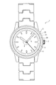
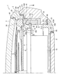
FIG. 1 is an overall plan view showing a timepiece according to a first embodiment of the present invention. FIG. 2 is a partial cross-sectional view of the outer periphery of the timepiece according to the first embodiment.
[時計の概略構成]
図1において、時計1は、指針5を駆動させることで時刻を表示する装置である。本実施の形態では、時計1として、腕に装着可能な腕時計を例示するが、これに限定されるものではなく、例えば携帯可能な懐中時計など、いかなる携帯式時計であってもよく、さらに、携帯式時計に限らず、置き時計などの時計などにおいて、本発明を適用してもよい。
そして、時計1は、図1および図2に示すように、外装部材2と、風防ガラス3と、風防ガラス3から視認可能な文字板4と、外装部材2に収納されるムーブメント10(図2参照)と、を備えている。
[Schematic configuration of the watch]
In FIG. 1, a timepiece 1 is a device that displays time by driving a
As shown in FIGS. 1 and 2, the timepiece 1 includes an
外装部材2は、図2に示すように、胴部21と、風防保持部22と、裏蓋23と、ダイヤルリング24と、を備えている。
As shown in FIG. 2, the
胴部21は、例えば金属により形成される略筒状部材である。この胴部21は、時計厚み方向に沿う一端面に、風防保持段差部211が形成され、この風防保持段差部211に、例えばパッキンなどの防水部材6Aを介して風防保持部22が固定されている。また、胴部21は、時計1の3時方向において、内外を貫通する挿通孔(図示略)を備え、この挿通孔にムーブメント10に接続され、ムーブメントの動作を制御可能な竜頭7が挿通される。
また、胴部21は、時計厚み方向に沿う他端側が時計内部側(ムーブメント10に対向する側に突出する保持突出部212を備えている。さらに、この保持突出部212の内周面には、雌ネジ部212Aが形成され、裏蓋23に形成される雄ネジ部23Aが螺合されることで、裏蓋23を固定する。さらに、胴部21の他端面には、略環状の凹部213が形成されて、例えばパッキンなどの防水部材6Bが配設され、胴部21および裏蓋23の間の防水性が確保される。
さらに、胴部21には、内外を貫通する図示しない竜頭孔が形成され、図1に示すような竜頭7がこの竜頭孔に貫通されて配置されている。
The trunk |
Further, the
Further, a crown hole (not shown) penetrating the inside and outside of the
風防保持部22は、環状に形成され、上述したように、防水部材6Aを介して胴部21に固定される。また、風防保持部22の内周部には、防水部材6Cを介して風防ガラス3が固定される。
The
裏蓋23は、略環状に形成され、胴部21に対向する面に環状の雄ネジ部23Aが突出形成される。そして、上記したように、この雄ネジ部23Aを胴部21の雌ネジ部212Aに螺合させることで、裏蓋23が胴部21に固定される。そして、この裏蓋23は、中心に形成される円形孔部231に、防水部材6Dを介して裏蓋風防ガラス8が固定される。
The
ダイヤルリング24は、環状に形成され、後述する当接部材である文字板受リング25とともに、文字板4を所定位置で位置決めする。具体的には、このダイヤルリング24は、外周面に沿って、径外方向に突出する固定部241を備え、この固定部241は、風防保持部22の内周部に係止される。また、ダイヤルリング24の上面側は、風防ガラス3に対向する傾斜面が形成される。この傾斜面に例えば風防ガラス3から視認可能な目盛などが形成される構成としてもよい。
また、ダイヤルリング24の下部には、胴部21の保持突出部212の上面に対向する平面状の保持面242が形成されている。さらに、保持面242の内周側には、文字板4の外周面に当接する文字板保持突部243、および文字板4の上面の外周部に当接する文字板押さえ部244が形成されている。
The
In addition, a
文字板受リング25は、略環状に形成され、上面が文字板4の下面に当接する。また、文字板受リング25は、外周部から径外方向に突出する枠受部251を備え、この枠受部251は、後述する保持枠30の上面に当接する。また、文字板受リング25の下面側には、ムーブメント10の地板11を係止可能な係止段差部252が形成されている。
そして、文字板受リング25は、上述したダイヤルリング24の文字板押さえ部244とにより文字板4の外周部を挟み込むことで、文字板4を固定する。
The
And the
ムーブメント10は、内部に指針5を駆動させる駆動力を発生する駆動源、駆動源からの駆動力を指針5に伝達させて、指針5を所定駆動周期で駆動させる駆動輪列、指針5の駆動周期を調整する調速回路などを備えた装置である。なお、駆動源としては、ゼンマイを駆動させて駆動力を得る構成、ステッピングモーターを駆動させる構成など、いずれの構成としてもよい。また、ムーブメント内に二次電池を内蔵し、発電機構により発電される電力を二次電池に蓄電させて、二次電池の蓄電量により駆動源や駆動回路、調速回路を駆動させる構成などとしてもよい。さらには、ムーブメント10内に、アンテナを内蔵し、時刻情報を有する電波を受信することで自動時刻修正を実施可能な電波時計や、GPSからの情報により時刻を修正するGPS時計などとしてもよい。
The
そして、ムーブメント10は、図2に示すように、筒状に形成される保持枠30に保持された状態で、時計1の外装部材2の内部に収納される。
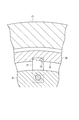
具体的には、ムーブメント10は、各構成が保持される地板11を備え、この地板11の外周部には、留め爪12が複数、例えば均等間隔で固定されている。図3は、図2のIII-III線を断面した断面図である。図3に示すように、留め爪12は、例えば弾性を有する金属などにより、長手形状に形成されている。そして、留め爪12の長手方向の一端側が地板11に例えばネジ止めにより固定され、他端側が保持枠30に形成される係合孔32に係合される。
As shown in FIG. 2, the
Specifically, the
保持枠30は、例えば金属もしくは合成樹脂により形成される部材であり、図2および図3に示すように、筒状に形成される。そして、保持枠30の内周面31には、上述した留め爪12を係止する係合孔32が形成されている。
この係合孔32は、留め爪12の長手方向に直交する幅方向の寸法と、略同寸法の幅寸法aに形成され、孔深さ寸法bは、留め爪12の突出先端縁を係合可能な寸法に形成される。従って、係合孔32に留め爪12を係合させることで、ムーブメント10の水平方向の移動が規制され、ムーブメント10が所定位置に位置決めされ、外装部材2に対するムーブメント10の回転が規制される。
なお、係合孔32との幅寸法としては、これに限定されず、例えば、留め爪12の回転が規制される構成に形成されていればよい。例えば、係合孔32が留め爪12の突出先端の回動軌跡に沿った形状に形成され、係合孔32内に留め爪12を位置決めする位置決め部が設けられる構成としてもよい。このような構成では、保持枠30にムーブメント10を固定する際に、留め爪12を回動させるだけで係合孔32に係合させることが可能となり、組み立て効率を向上させることが可能となる。
The holding
The
In addition, as a width dimension with the
また、係合孔32の時計厚み方向の寸法cは、留め爪12の厚み寸法に対して大きく形成される。すなわち、係合孔32は、時計厚み方向に対しては、留め爪12が係合孔32内で時計厚み方向に変位可能な形状に形成されている。
Further, the dimension c in the clockwise thickness direction of the
そして、保持枠30の時計厚み方向に両側には、第一緩衝部材41および第二緩衝部材42が配置され、これら第一緩衝部材41および第二緩衝部材42を介して保持枠30が時計1の内部に収納される。
具体的には、第一緩衝部材41は、時計厚み方向における風防ガラス3側に配置される部材であり、断面L字型のリング形状に形成される。そして、第一緩衝部材41は、保持枠30の上面および外周面、ダイヤルリング24の保持面242、および胴部21の内周面に当接して配置され、ダイヤルリング24や胴部21から保持枠30に伝わる衝撃を緩和する。第二緩衝部材42は、時計厚み方向における裏蓋23側に配置される部材であり、第一緩衝部材41と同様、断面L字型のリング形状に形成される。そして、この第二緩衝部材42は、保持枠30の下面および外周面、胴部21の保持突出部212の上面、および胴部21の内周面に当接し、胴部21から保持枠30に伝わる衝撃を緩和する。これらの第一および第二緩衝部材41,42としては、衝撃が加わった際に弾性変形して衝撃力を吸収可能な素材であれば、いかなる素材により形成されていてもよく、例えば合成ゴムなどを用いることができる。
A
Specifically, the
上述のような時計1では、ムーブメント10は、文字板受リング25の係止段差部252および留め爪12により挟持されることで、時計1の内部で略浮いた状態で保持される。
すなわち、上述したように、ムーブメント10は、地板11の上面の外周部、および地板11の外周面が、文字板受リング25の係止段差部252に当接し、かつ地板11に固定される留め爪12が係合孔32の時計厚み方向における裏蓋23側の面に当接する。これにより、地板11は、文字板受リング25により文字板4側への移動が規制され、留め爪12により裏蓋23側への移動が規制され、時計厚み方向における所定高さ位置で保持される。
ここで、ムーブメント10は、保持枠30との間には、留め爪12の長手寸法に応じた隙間が形成され、裏蓋23との間にも隙間が形成される。したがって、ムーブメント10は、地板11の外周部のみで外装部材2に連結される構成となり、略浮いた状態で保持される。
In the timepiece 1 as described above, the
In other words, as described above, the
Here, a gap corresponding to the longitudinal dimension of the retaining
上述したような時計1では、時計厚み方向に対して衝撃が加わった際、例えば風防保持部22に衝撃が加わった場合、その衝撃力はダイヤルリング24から第一緩衝部材41に伝達され、ムーブメント10への衝撃が緩和される。また、ダイヤルリング24から文字板4、文字板受リング25に衝撃力が伝達された場合でも、文字板受リング25が保持枠30に当接しているため、その衝撃力が保持枠30に分散され、かつ保持枠30から第二緩衝部材42に衝撃力が吸収されることで、ムーブメント10への衝撃が緩和される。さらに、衝撃により保持枠30が時計厚み方向に対して振動した場合、例えば保持枠30が裏蓋23側に移動した場合、留め爪12は係合孔32内で移動可能であるため、留め爪12からムーブメント10に振動が伝達されない。さらに、例えば保持枠30が衝撃により風防ガラス3側に移動した場合でも、留め爪12が弾性を有するため、留め爪12が撓むことにより衝撃が吸収され、ムーブメント10に衝撃力が伝達されない。
さらには、時計1の水平方向に対して衝撃が加わった場合、例えば胴部21に水平方向の衝撃が加わった場合、胴部からの衝撃が第一および第二緩衝部材41,42により吸収され、保持枠30およびムーブメント10には衝撃力が伝達されない。
また、ムーブメント10が時計1の内部において、略浮いた状態で保持されているため、裏蓋23や胴部21から直接衝撃力が伝達されない。例えば、ムーブメント10への衝撃を緩和するために裏蓋23とムーブメント10との間、ムーブメント10と保持枠30との間に緩衝部材を配置すると、緩衝部材により衝撃が緩和されるものの、この緩衝部材を介してムーブメントに衝撃が伝達されることとなる。これに対して、ムーブメント10が浮いた状態で保持される本実施の形態の時計1では、裏蓋23や胴部21に衝撃が加わった場合でも、ムーブメント10に直接衝撃が伝達されない。
In the timepiece 1 as described above, when an impact is applied in the thickness direction of the watch, for example, when an impact is applied to the
Furthermore, when an impact is applied to the horizontal direction of the timepiece 1, for example, when an impact in the horizontal direction is applied to the
Further, since the
[第一の実施の形態の作用効果]
上述したように、第一の実施の形態の時計1では、指針5を駆動させるムーブメント10を保持する保持枠30の時計厚み方向の両側に、第一および第二緩衝部材41,42が設けられ、保持枠30はこれらの第一および第二緩衝部材41,42を介して外装部材2内に収納される。
このため、外装部材2に衝撃が加わった際に、第一および第二緩衝部材41,42により衝撃力が吸収されるため、保持枠30に衝撃力が伝達されない、または伝達される衝撃力を抑えることができる。したがって、保持枠30に保持されるムーブメント10に伝達される衝撃力も緩和され、衝撃による時計精度の悪化などの悪影響を防止することができる。特に、本実施の形態のような腕時計では、風防ガラス3側から時計厚み方向に衝撃が加わる場合が多く想定され、このような時計厚み方向の衝撃に対して、保持枠30の時計厚み方向の両端側に第一および第二緩衝部材41,42が配置されるため、衝撃をより効果的に吸収することができる。
[Operational effects of the first embodiment]
As described above, in the timepiece 1 of the first embodiment, the first and
For this reason, when an impact is applied to the
また、ムーブメント10の地板11の外周部には、複数個所に留め爪12が径外方向に突出形成され、保持枠30の係合孔32に係合され、地板11の上面外周部は、文字板受リング25の係止段差部252に係止されている。これにより、ムーブメント10は、文字板受リング25により風防ガラス3側への移動が規制され、留め爪12により裏蓋23側への移動が規制されることとなる。また、この時、保持枠30とムーブメント10との間には、留め爪12の長手寸法に応じた隙間が形成されることで、保持枠30からムーブメント10での衝撃伝達経路が留め爪12部分のみとなる。このため、保持枠30に衝撃が加わった場合でも、保持枠30がムーブメント10に接していないため、衝撃の伝達が抑えられ、仮に衝撃力が加わった場合でも、留め爪12部分のみで衝撃力が伝達されるため、その衝撃伝達量が小さく、衝撃によるムーブメント10への影響をより効果的に抑えることができる。
また、外装部材2であるダイヤルリング24に加わった衝撃は、ダイヤルリング24に当接する第一緩衝部材41にそのほとんどが吸収されることとなるが、衝撃力の一部が文字板4を介して、地板11に当接する文字板受リング25に伝達される場合もある。ここで、文字板受リング25の下面が地板11のみに当接する場合、その衝撃力がムーブメント10のみに伝達されることとなる。これに対して、上記時計1では、文字板受リング25が保持枠30に当接されているため、文字板4を介して文字板受リング25に伝達される衝撃力をさらに保持枠30に分散させることができ、ムーブメント10に伝達される衝撃をより確実に抑えることができる。
なお、本実施の形態では、地板11と文字板受リング25とが直接接する構成を例示したが、これに限定されず、例えば地板11と、文字板受リング25の係止段差部252との間に別途緩衝部材を設ける構成などとしてもよく、この場合、文字板受リング25に伝達される衝撃を保持枠30に逃がすことができることに加え、ムーブメント10側に流れる衝撃力を緩衝部材により吸収することができ、より確実にムーブメント10への衝撃伝達を防止することができる。
Further, on the outer peripheral portion of the
Further, most of the impact applied to the
In addition, in this Embodiment, although the structure which the
また、係合孔32の幅寸法aは、留め爪12の幅寸法と同寸法に形成されている。
このため、ムーブメント10が保持枠30に対して回動せず、時計1の所定位置に確実に位置決めすることができる。
さらに、係合孔32の高さ寸法cは、留め爪12の厚み寸法よりも大きく形成されている。このため、衝撃により保持枠30が時計厚み方向の裏蓋23側に移動した場合でも、留め爪12が係合孔32内を時計厚み方向に移動することが可能でムーブメント10への衝撃伝達をさらに確実に防止することができる。
さらには、留め爪12は、弾性変形可能な金属素材により形成されている。このため、保持枠30が衝撃により風防ガラス3に変位した場合でも、留め爪12が撓むことでムーブメント10での衝撃伝達をより確実に防止することができる。
Further, the width dimension a of the
For this reason, the
Further, the height dimension c of the
Furthermore, the retaining
そして、第一緩衝部材41および第二緩衝部材42は、断面略L字型の環状に形成され、これらの第一および第二緩衝部材41,42により保持枠30の時計厚み方向に沿う両端面、および外周面の一部が覆われる。そして、第一緩衝部材41は、上面側がダイヤルリング24に、外周面が胴部21の内周面に当接し、第二緩衝部材42は、下面側が胴部21の保持突出部212の上面に、外周面が胴部21の内周面に当接している。
このため、これらの第一および第二緩衝部材41,42により、時計の厚み方向に対する衝撃だけでなく、胴部21から内周面から伝達される水平方向に対する衝撃をも吸収することができ、ムーブメント10への衝撃伝達をより確実に防止することができる。
The
For this reason, the first and
[第二の実施の形態]
次に、本発明に係る第二の実施の形態の時計について、図面に基づいて説明する。
図4は、第二の実施の形態における時計の一部の断面図である。なお、第二の実施の形態の説明に当たり、第一の実施の形態と同一構成については同符号を付し、その説明を省略または簡略する。
[Second Embodiment]
Next, a timepiece according to a second embodiment of the invention will be described with reference to the drawings.
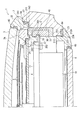
FIG. 4 is a cross-sectional view of a part of the timepiece according to the second embodiment. In the description of the second embodiment, the same components as those in the first embodiment are denoted by the same reference numerals, and the description thereof is omitted or simplified.
上記第一の実施の形態では、保持枠30の時計厚み方向の両側に第一および第二緩衝部材41,42の2部材を配置することでムーブメント10への衝撃伝達を軽減させる構成を示したが、第二の実施の形態では、1部材の緩衝部材43によりムーブメント10への衝撃伝達を軽減する。
具体的には、第二の実施の形態の時計1は、第一の実施の形態と同様に、外装部材2の内部に、保持枠30に保持されたムーブメント10が収納される。ここで、第二の実施の形態の時計1は、図4に示すように、保持枠30の時計厚み方向に一端面から外周面を経て他端面に亘る範囲で断面略コ字状の環形状に形成される緩衝部材43を備えている。また、緩衝部材43は、時計厚み方向における上面がダイヤルリング24に当接し、時計厚み方向の下面が胴部21の保持突出部212の上面に当接し、外周面の全面が胴部21の内周面に当接して配置される。そして、この緩衝部材43は、上述した第一および第二緩衝部材41,42と同様、例えば合成ゴムなど、弾性変形することで衝撃力を吸収可能な素材により形成される。
また、緩衝部材43は、時計1の3時方向において内外を貫通する貫通孔(図示略)が形成され、この貫通孔に竜頭7が挿通される。
In the first embodiment, the configuration in which the shock transmission to the
Specifically, in the timepiece 1 according to the second embodiment, the
Further, the
[第二の実施の形態の作用効果]
上記第二の実施の形態の時計1においても、第一の実施の形態と同様の効果が得られる。すなわち、外装部材2に衝撃が加わった際に、緩衝部材43により衝撃力が吸収されるため、保持枠30への衝撃伝達を抑えることができる。
また、ムーブメント10の外周部から留め爪12が突出して保持枠30の係合孔32に係合され、ムーブメント10の地板11が文字板受リング25の係止段差部252に係止されている。このため、ムーブメント10を時計1内の所定位置に位置決めすることができるとともに、ムーブメント10および保持枠30の間に隙間が形成されることで、保持枠30に加えられた衝撃がムーブメント10に伝達されず、より確実にムーブメントへの衝撃伝達を抑えることができる。
[Operational effects of the second embodiment]
In the timepiece 1 of the second embodiment, the same effect as the first embodiment can be obtained. That is, when an impact is applied to the
Further, the retaining
これに加えて、緩衝部材43が1部材により形成されているため、時計1の組み立て効率を向上させることができる。また、緩衝部材43の外周面の全面が胴部21の内周面に当接するため、胴部21に加えられた衝撃を緩衝部材43全体に分散させることができ、衝撃をより軽減させることが可能となる。
In addition, since the
〔実施の形態の変形〕
本発明は、前記実施の形態に限定されるものではなく、本発明の目的を達成できる他の構成等を含み、以下に示すような変形等も本発明に含まれる。
[Modification of Embodiment]
The present invention is not limited to the above-described embodiment, and includes other configurations that can achieve the object of the present invention, and includes the following modifications and the like.
例えば、上記第一および第二の実施の形態では、時計1として腕時計を例示したが、これに限定されず、上述したように、例えば、懐中時計などのその他の携帯時計であってもよく、置き時計などの固定式時計であってもよい。 For example, in the first and second embodiments, a wristwatch is illustrated as the watch 1, but the watch 1 is not limited thereto, and may be another portable watch such as a pocket watch as described above. It may be a fixed clock such as a table clock.
また、時計1の駆動方式としては、ゼンマイの駆動力をテンプなどの調速手段により調速して指針を駆動させる機械式時計や、水晶振動子から出力される周波数に基づいて、モーターにより駆動される指針を調速するクォーツ式時計など、いかなるタイプの時計に対しても本発明を適用することができる。また、指針を駆動させる時計に限らず、例えば液晶ディスプレイに時刻を表示させるデジタル表示時計などにおいても、上記構成を用いてもよく、電子回路や液晶回路が組み込まれるムーブメントを振動から保護することができる。 The timepiece 1 is driven by a mechanical timepiece that drives the hands by adjusting the driving force of the mainspring with a speed adjusting means such as a balance, or by a motor based on the frequency output from the crystal unit. The present invention can be applied to any type of timepiece, such as a quartz type timepiece that adjusts the pointer. In addition to the timepiece that drives the hands, for example, a digital display timepiece that displays the time on a liquid crystal display, the above-described configuration may be used to protect a movement incorporating an electronic circuit or a liquid crystal circuit from vibration. it can.
また、ムーブメント10および文字板受リング25の間にさらに緩衝部材を設ける構成としてもよく、留め爪12および保持枠30との間にも緩衝部材を設ける構成としてもよい。このような構成では、さらにムーブメント10に伝達される衝撃を緩和することができる。
Further, a buffer member may be further provided between the
また、上記実施の形態において、第一緩衝部材41および緩衝部材43の上面が、外装部材2を構成するダイヤルリング24に当接する構成としたが、これに限定されない。例えば、胴部21の上端部に内径側に突出する突出部を形成し、この突出部に第一緩衝部材41および緩衝部材43の上面を当接させる構成としてもよく、風防保持部22に第一緩衝部材41および緩衝部材43の上面を当接させる構成としてもよい。第二緩衝部材42および緩衝部材43の下面についても同様であり、胴部21の保持突出部212の上面に当接する構成としたが、例えば裏蓋23などに当接することで衝撃を吸収する構成としてもよい。
Moreover, in the said embodiment, although the upper surface of the
その他、本発明の実施の際の具体的な構造および手順は、本発明の目的を達成できる範囲で他の構造などに適宜変更できる。 In addition, the specific structure and procedure for carrying out the present invention can be appropriately changed to other structures and the like within a range in which the object of the present invention can be achieved.
1…時計、2…外装部材、10…ムーブメント、12…留め爪、21…外装部材を構成する胴部、22…外装部材を構成する風防保持部、23…外装部材を構成する裏蓋、24…外装部材を構成するダイヤルリング、25…当接部材である文字板受リング、30…保持枠、32…係合孔、41…第一緩衝部材、42…第二緩衝部材、43…緩衝部材。 DESCRIPTION OF SYMBOLS 1 ... Clock, 2 ... Exterior member, 10 ... Movement, 12 ... Fastening claw, 21 ... Body part which comprises exterior member, 22 ... Windshield holding part which comprises exterior member, 23 ... Back cover which comprises exterior member, 24 DESCRIPTION OF SYMBOLS ... Dial ring which comprises exterior member, 25 ... Dial plate receiving ring which is contact member, 30 ... Holding frame, 32 ... Engagement hole, 41 ... First buffer member, 42 ... Second buffer member, 43 ... Buffer member .
Claims (4)
前記ムーブメントを保持する略環状の保持枠と、
前記ムーブメントを時計厚み方向の両側から挟持する緩衝部材と、
前記ムーブメント、前記保持枠、および前記緩衝部材を収納する外装部材と、
を具備したことを特徴とする時計。 A movement that drives the hands to display the time,
A substantially annular holding frame for holding the movement;
A cushioning member for clamping the movement from both sides in the watch thickness direction;
An exterior member that houses the movement, the holding frame, and the buffer member;
A watch comprising:
前記外装部材に固定されるとともに、前記ムーブメントの時計厚み方向の一端面の少なくとも一部、および前記保持枠の時計厚み方向に一端面の少なくとも一部に当接する当接部材と、
前記ムーブメントの外周部に設けられ、前記保持枠に向かって突出する留め爪と、を備え、
前記保持枠は、前記ムーブメントに対向する面に、前記留め爪を係合する係合孔を備え、
前記ムーブメントは、前記当接部材および前記留め爪により、前記保持枠との間に隙間が介在される状態で保持される
ことを特徴とする時計。 The timepiece according to claim 1,
An abutting member fixed to the exterior member and abutting at least a part of one end face of the movement in the clockwise thickness direction and at least a part of the one end face in the clockwise thickness direction of the holding frame;
A claw provided on an outer periphery of the movement and projecting toward the holding frame;
The holding frame includes an engagement hole that engages the retaining pawl on a surface facing the movement,
The timepiece, wherein the movement is held by the contact member and the retaining claws with a gap interposed between the movement frame and the holding frame.
前記緩衝部材は、前記ムーブメントの厚み方向における一端側に設けられるとともに、前記ムーブメントの一端面および側面に当接する断面L字型の環状の第一緩衝部材、および前記ムーブメントの厚み方向における他端側に設けられるとともに、前記ムーブメントの他端面および側面に当接する断面L字型の環状の第二緩衝部材を有する
ことを特徴とする時計。 The timepiece according to claim 1 or 2,
The shock-absorbing member is provided on one end side in the thickness direction of the movement, and has an L-shaped annular first shock-absorbing member that abuts against one end surface and a side surface of the movement, and the other end side in the thickness direction of the movement. And a second shock absorbing member having an L-shaped cross section that abuts against the other end face and the side face of the movement.
前記緩衝部材は、前記ムーブメントの前記時計厚み方向における両端面および側面を覆う断面コ字型の環状に形成される
ことを特徴とする時計。 The timepiece according to claim 1 or 2,
The timepiece characterized in that the buffer member is formed in an annular shape having a U-shaped cross section covering both end faces and side faces in the watch thickness direction of the movement.
Priority Applications (1)
| Application Number | Priority Date | Filing Date | Title |
|---|---|---|---|
| JP2009134768A JP2010281663A (en) | 2009-06-04 | 2009-06-04 | clock |
Applications Claiming Priority (1)
| Application Number | Priority Date | Filing Date | Title |
|---|---|---|---|
| JP2009134768A JP2010281663A (en) | 2009-06-04 | 2009-06-04 | clock |
Publications (1)
| Publication Number | Publication Date |
|---|---|
| JP2010281663A true JP2010281663A (en) | 2010-12-16 |
Family
ID=43538533
Family Applications (1)
| Application Number | Title | Priority Date | Filing Date |
|---|---|---|---|
| JP2009134768A Withdrawn JP2010281663A (en) | 2009-06-04 | 2009-06-04 | clock |
Country Status (1)
| Country | Link |
|---|---|
| JP (1) | JP2010281663A (en) |
Citations (7)
| Publication number | Priority date | Publication date | Assignee | Title |
|---|---|---|---|---|
| JPS4980771U (en) * | 1972-10-30 | 1974-07-12 | ||
| JPS4982367A (en) * | 1972-12-11 | 1974-08-08 | ||
| JPS4989570A (en) * | 1972-12-26 | 1974-08-27 | ||
| JPS507071U (en) * | 1973-05-18 | 1975-01-24 | ||
| JPS5310213Y1 (en) * | 1973-07-26 | 1978-03-17 | ||
| JPS5434351B2 (en) * | 1972-04-19 | 1979-10-26 | ||
| JP2000258560A (en) * | 1999-03-09 | 2000-09-22 | Citizen Watch Co Ltd | Watch case |
-
2009
- 2009-06-04 JP JP2009134768A patent/JP2010281663A/en not_active Withdrawn
Patent Citations (7)
| Publication number | Priority date | Publication date | Assignee | Title |
|---|---|---|---|---|
| JPS5434351B2 (en) * | 1972-04-19 | 1979-10-26 | ||
| JPS4980771U (en) * | 1972-10-30 | 1974-07-12 | ||
| JPS4982367A (en) * | 1972-12-11 | 1974-08-08 | ||
| JPS4989570A (en) * | 1972-12-26 | 1974-08-27 | ||
| JPS507071U (en) * | 1973-05-18 | 1975-01-24 | ||
| JPS5310213Y1 (en) * | 1973-07-26 | 1978-03-17 | ||
| JP2000258560A (en) * | 1999-03-09 | 2000-09-22 | Citizen Watch Co Ltd | Watch case |
Similar Documents
| Publication | Publication Date | Title |
|---|---|---|
| CN102200754B (en) | Shock absorbing member for wristwatch and wristwatch | |
| JP4905815B2 (en) | Cushioning member, impact buffering structure of wristwatch, and wristwatch | |
| CN102591189B (en) | Buffer member, shock buffering structure of electronic device, and electronic device | |
| US20090003141A1 (en) | Timepiece | |
| US9462716B2 (en) | Shock buffering structure of electronic device, and electronic device | |
| JP5623314B2 (en) | clock | |
| JP7240618B2 (en) | Switch device manufacturing method and watch manufacturing method | |
| JP5673700B2 (en) | Case structure | |
| JP6364763B2 (en) | Case and clock | |
| JP6493701B2 (en) | clock | |
| US11810737B2 (en) | Switch device and timepiece | |
| JP2016114553A (en) | clock | |
| CN108398875B (en) | Clock and watch | |
| JP2010281663A (en) | clock | |
| CN114063428B (en) | Exterior member, case, and timepiece | |
| JP2017223572A (en) | clock | |
| CN101334631A (en) | clock | |
| JP4599833B2 (en) | clock | |
| JP2008298725A (en) | Watch | |
| JP4968729B2 (en) | Shock absorber | |
| JP6292110B2 (en) | Case unit | |
| JP2011109305A (en) | Antenna device, and radiowave reception apparatus | |
| JP7771579B2 (en) | electronic equipment | |
| JP3728617B2 (en) | Wrist device | |
| JP2007225301A (en) | Dial |
Legal Events
| Date | Code | Title | Description |
|---|---|---|---|
| A621 | Written request for application examination |
Free format text: JAPANESE INTERMEDIATE CODE: A621 Effective date: 20120424 |
|
| A131 | Notification of reasons for refusal |
Free format text: JAPANESE INTERMEDIATE CODE: A131 Effective date: 20130514 |
|
| A977 | Report on retrieval |
Free format text: JAPANESE INTERMEDIATE CODE: A971007 Effective date: 20130515 |
|
| A761 | Written withdrawal of application |
Free format text: JAPANESE INTERMEDIATE CODE: A761 Effective date: 20130605 |