JP2010278564A - Mobile device - Google Patents
Mobile device Download PDFInfo
- Publication number
- JP2010278564A JP2010278564A JP2009126928A JP2009126928A JP2010278564A JP 2010278564 A JP2010278564 A JP 2010278564A JP 2009126928 A JP2009126928 A JP 2009126928A JP 2009126928 A JP2009126928 A JP 2009126928A JP 2010278564 A JP2010278564 A JP 2010278564A
- Authority
- JP
- Japan
- Prior art keywords
- access point
- storage unit
- wireless lan
- unit
- scan
- Prior art date
- Legal status (The legal status is an assumption and is not a legal conclusion. Google has not performed a legal analysis and makes no representation as to the accuracy of the status listed.)
- Granted
Links
Images

Classifications
-
- H—ELECTRICITY
- H04—ELECTRIC COMMUNICATION TECHNIQUE
- H04W—WIRELESS COMMUNICATION NETWORKS
- H04W48/00—Access restriction; Network selection; Access point selection
- H04W48/16—Discovering, processing access restriction or access information
-
- H—ELECTRICITY
- H04—ELECTRIC COMMUNICATION TECHNIQUE
- H04W—WIRELESS COMMUNICATION NETWORKS
- H04W52/00—Power management, e.g. Transmission Power Control [TPC] or power classes
- H04W52/02—Power saving arrangements
- H04W52/0209—Power saving arrangements in terminal devices
- H04W52/0261—Power saving arrangements in terminal devices managing power supply demand, e.g. depending on battery level
- H04W52/0274—Power saving arrangements in terminal devices managing power supply demand, e.g. depending on battery level by switching on or off the equipment or parts thereof
- H04W52/028—Power saving arrangements in terminal devices managing power supply demand, e.g. depending on battery level by switching on or off the equipment or parts thereof switching on or off only a part of the equipment circuit blocks
-
- H—ELECTRICITY
- H04—ELECTRIC COMMUNICATION TECHNIQUE
- H04W—WIRELESS COMMUNICATION NETWORKS
- H04W88/00—Devices specially adapted for wireless communication networks, e.g. terminals, base stations or access point devices
- H04W88/02—Terminal devices
-
- Y—GENERAL TAGGING OF NEW TECHNOLOGICAL DEVELOPMENTS; GENERAL TAGGING OF CROSS-SECTIONAL TECHNOLOGIES SPANNING OVER SEVERAL SECTIONS OF THE IPC; TECHNICAL SUBJECTS COVERED BY FORMER USPC CROSS-REFERENCE ART COLLECTIONS [XRACs] AND DIGESTS
- Y02—TECHNOLOGIES OR APPLICATIONS FOR MITIGATION OR ADAPTATION AGAINST CLIMATE CHANGE
- Y02D—CLIMATE CHANGE MITIGATION TECHNOLOGIES IN INFORMATION AND COMMUNICATION TECHNOLOGIES [ICT], I.E. INFORMATION AND COMMUNICATION TECHNOLOGIES AIMING AT THE REDUCTION OF THEIR OWN ENERGY USE
- Y02D30/00—Reducing energy consumption in communication networks
- Y02D30/70—Reducing energy consumption in communication networks in wireless communication networks
Landscapes
- Engineering & Computer Science (AREA)
- Computer Security & Cryptography (AREA)
- Computer Networks & Wireless Communication (AREA)
- Signal Processing (AREA)
- Mobile Radio Communication Systems (AREA)
Abstract
【課題】携帯端末の省電力化のために、無線LAN通信部のスキャン対象APリストに設定するAPの個数を1個とし、このことにより発生する利便性の低下を抑えることができる携帯端末を提供する。
【解決手段】無線LAN設定機能2は、ユーザ登録の自動起動対象のホームAPをAPリスト記憶部3内のホームAP記憶部に記録する。無線LAN設定機能2は、APリスト記憶部3内のユーザ登録の優先度の付いた複数のAPリストのAPを優先度順に無線LANカード20内のスキャン対象AP記憶部24に記録し、無線LANカード20に無線LAN通信させる。また、APリスト記憶部3内に接続中APとして接続成功したAPが記録される。周期的に起動されるサスペンド起動処理機能10は、AP圏内であれば、前記接続中APをスキャン対象AP記憶部24に記録し、AP圏外であれば、前記ホームAPをスキャン対象AP記憶部24に記録する。
【選択図】図2To reduce power consumption of a mobile terminal, a mobile terminal capable of suppressing a decrease in convenience caused by setting the number of APs set in a scan target AP list of a wireless LAN communication unit to one. provide.
A wireless LAN setting function 2 records a home AP to be automatically activated for user registration in a home AP storage unit in an AP list storage unit 3. The wireless LAN setting function 2 records APs of a plurality of AP lists with priority of user registration in the AP list storage unit 3 in the scan target AP storage unit 24 in the wireless LAN card 20 in order of priority. The card 20 is caused to perform wireless LAN communication. In the AP list storage unit 3, an AP that has been successfully connected is recorded as a connecting AP. The suspend activation processing function 10 that is periodically activated records the connected AP in the scan target AP storage unit 24 if within the AP range, and stores the home AP in the scan target AP storage unit 24 if out of the AP range. To record.
[Selection] Figure 2
Description
本発明は、Wake On Wireless LAN方式の無線LAN通信部を搭載した携帯端末に関する。 The present invention relates to a portable terminal equipped with a Wake On Wireless LAN wireless LAN communication unit.
Wake On Wireless LAN方式の端末は、待機状態で、端末内に予め登録された無線LANアクセスポイント(AP)の探索のためのAPスキャンを行い、端末が移動してAPのエリア内に入ってスキャンによりそのAPが検出できたときに、端末内のその他必要な部分を自動起動して無線LAN通信を行うことにより、使用者の利便性を向上することができる。 A Wake On Wireless LAN system terminal performs an AP scan for searching for a wireless LAN access point (AP) registered in the terminal in a standby state, and the terminal moves to enter the AP area and scans. Thus, when the AP can be detected, the convenience of the user can be improved by automatically starting other necessary parts in the terminal and performing wireless LAN communication.
このような自動起動方式の特許文献として、移動端末の電源制御方法及びシステムがある(例えば、特許文献1参照。)。この特許文献1の移動端末1は、スリープ時にも動作するビーコン信号認識部102を有し、ビーコン信号認識部102内にAPのESSID登録リストを有する。ビーコン信号認識部102は、APからのビーコン信号を受信すると、ビーコン信号中のAPのESSIDが、ESSID登録リストに登録されたESSIDと一致するかを判定し、いずれか1つと一致する場合、移動端末1全体を自動起動する。
As a patent document of such an automatic startup method, there is a power control method and system for a mobile terminal (see, for example, Patent Document 1). The
ところで、端末が行うAPスキャンの方式としては、パッシブスキャンとアクティブスキャンがある。パッシブスキャンは、APのチャネルから来るビーコンフレームを取得して、ビーコンフレーム中のAPのESSIDを認識するものであるが、APがESSIDを隠蔽している場合もある。したがって、通常は、端末が自らAPに要求信号を送出してスキャンするアクティブスキャンが行われる。 By the way, there are a passive scan and an active scan as a method of AP scan performed by the terminal. The passive scan acquires the beacon frame coming from the AP channel and recognizes the ESSID of the AP in the beacon frame. However, the AP may conceal the ESSID. Therefore, normally, an active scan is performed in which the terminal sends a request signal to the AP for scanning.
アクティブスキャンについて次に説明する。
図7は、無線LAN通信のアクティブスキャンを説明する図である。端末の無線LAN通信部のアクティブスキャンを実行するAPスキャン部は、APスキャン部のスキャン対象APリストに予め登録してあるAPを対象としてスキャンを実行する。スキャン対象APリストには、予め、AP1とAP2が登録してあるものとする。
The active scan will be described next.
FIG. 7 is a diagram for explaining an active scan of wireless LAN communication. The AP scanning unit that performs active scanning of the wireless LAN communication unit of the terminal performs scanning for APs registered in advance in the scanning target AP list of the AP scanning unit. It is assumed that AP1 and AP2 are registered in advance in the scan target AP list.
端末のAPスキャン部は、待機状態で動作可能となっており、まずAP1を指定したProbe Req信号を1ch〜13chで順次送信し、各ch毎にAP1からの応答であるProbe Resp(1ch)〜Probe Resp (13ch)の受信待ちを行う。 The AP scan unit of the terminal is operable in a standby state. First, a Probe Req signal designating AP1 is sequentially transmitted from 1ch to 13ch, and a response from AP1 is transmitted from AP1 for each ch. Wait for Probe Resp (13ch) reception.
端末のAPスキャン部は、この応答Probe Respの受信ができない場合は、次に、AP2を指定したProbe Req信号を1ch〜13chで順次送信し、各ch毎にAP2からの応答であるProbe Resp(1ch)〜Probe Resp (13ch)の受信待ちを行う。 If the AP scan unit of the terminal cannot receive the response Probe Resp, it next transmits a Probe Req signal designating AP2 in order from 1ch to 13ch, and Probe Resp () is a response from AP2 for each ch. Wait for receiving 1ch) to Probe Resp (13ch).
端末がAPのエリア外にいる場合は、上記応答Probe Respは返って来ないので、端末のAPスキャン部は、AP1を指定した1ch〜13chのスキャンとAP2を指定した1ch〜13chのスキャンとを1サイクルとして、2サイクル繰り返し、応答がない場合は、一旦休止して、所定時間後に再び、同様のスキャンを行い続ける。 When the terminal is outside the area of the AP, the above-mentioned response Probe Resp is not returned, so the AP scan unit of the terminal performs a scan of 1ch to 13ch that specifies AP1 and a scan of 1ch to 13ch that specifies AP2. If there is no response in one cycle as one cycle, if there is no response, it is paused and the same scan is continued again after a predetermined time.
端末がAPのエリアに入って、端末のProbe Req信号を受信できたAPは、1ch〜13chの内、通信可能な空きchで、応答信号Probe Respを返す。端末のAPスキャン部は、Probe Respを受信し、Probe Resp中のAPのESSIDを認識した時点でスキャンを終了して、端末全体を起動させて、APとの間で無線LANの通信手順に移行する。 The AP that has entered the AP area and has received the Probe Req signal of the terminal returns a response signal Probe Resp with an available communication channel from 1ch to 13ch. The AP scan unit of the terminal receives the probe resp, terminates the scan when it recognizes the ESSID of the AP in the probe resp, starts the entire terminal, and shifts to the wireless LAN communication procedure with the AP To do.
このように、端末のAPスキャン部は、スキャン対象APリストに登録してあるAP分のスキャンを行い、端末が登録APのエリア内に入ったときに起動できるものであり、使用者の利便性が向上する。しかし、端末の消費電力の観点からは、Probe Req信号1ch分の送信に例えば300mAの電流、受信待ちに200mAの電流とかなり大きな消費電力であり、これを1ch〜13chに対して行い、さらに、スキャン対象APリストに登録してあるAPの数に比例して増える。したがって、スキャン対象APリストへのAP登録数が増えると、使用者の利便性は上がるが、消費電力が増えるという相反する問題がある。 As described above, the AP scan unit of the terminal scans for the APs registered in the scan target AP list, and can be activated when the terminal enters the area of the registered AP. Will improve. However, from the viewpoint of the power consumption of the terminal, for example, a current of 300 mA is transmitted for Probe Req signal 1ch and a current of 200 mA is awaiting reception, which is a considerably large power consumption, and this is performed for 1ch to 13ch. The number increases in proportion to the number of APs registered in the scan target AP list. Therefore, when the number of AP registrations in the scan target AP list increases, the convenience of the user increases, but there is a conflicting problem that power consumption increases.
端末の使用者にとっては、無線LAN通信を自動起動または手動起動のいずれでも行える必要がある。使用者が、自動起動対象のAPとして省電力のためにAP1のみを登録操作した場合、無線LAN通信部を制御する端末内の上位のアプリケーション部分である主制御部は、無線LAN通信部のスキャン対象APリストに、AP1のみを設定する。 For the user of the terminal, it is necessary that the wireless LAN communication can be performed either automatically or manually. When the user registers only AP1 for power saving as the AP to be automatically activated, the main control unit, which is the upper application part in the terminal that controls the wireless LAN communication unit, scans the wireless LAN communication unit. Only AP1 is set in the target AP list.
あるいは、使用者が、自動起動対象の登録AP1以外のAP2と手動起動で通信したい状況が発生して、AP2との間の手動起動操作を行った場合、主制御部は、無線LAN通信部のスキャン対象APリストに、AP2を設定する。 Alternatively, when the user wants to communicate with AP2 other than the registered AP1 to be automatically activated by manual activation and performs a manual activation operation with AP2, the main control unit AP2 is set in the scan target AP list.
無線LAN通信部のスキャン対象APリストには、複数個のAPを登録することができるが、省電力の観点からは、1個のみが望ましい。無線LAN通信部は、単純に、スキャン対象APリストに登録されているAP全てに対してスキャンを行うものであり、そのAPが上位の主制御部により自動起動用または手動起動用として設定されたものであるかの認識はしていない。無線LAN通信部は、該当APを検出したら、スキャン対象AP検出信号を主制御部に送出し、これを受けた主制御部は自動起動か手動起動かに応じた処理を行うものである。 A plurality of APs can be registered in the scan target AP list of the wireless LAN communication unit, but only one is desirable from the viewpoint of power saving. The wireless LAN communication unit simply scans all APs registered in the scan target AP list, and the AP is set for automatic activation or manual activation by the upper main control unit. We do not recognize whether it is a thing. When the wireless LAN communication unit detects the corresponding AP, the wireless LAN communication unit sends a scan target AP detection signal to the main control unit, and the main control unit that receives the AP performs processing according to whether it is automatically activated or manually activated.
したがって、使用者は、手動起動を行った場合には、無線LAN通信部のスキャン対象APリストの内容が変わってしまうので、自動起動対象のAP登録を再度やり直す必要が生じ、使用者の利便性が低下してしまうという問題がある。 Therefore, when the user performs manual activation, the content of the scan target AP list of the wireless LAN communication unit changes, so that it is necessary to re-register the automatic activation target AP again, which is convenient for the user. There is a problem that will decrease.
特許文献1の移動端末では、自動起動対象のAPを登録する記載はあるが、手動起動対象のAPの登録に関する記載はない。
In the mobile terminal of
本発明では、携帯端末の省電力化のために、無線LAN通信部のスキャン対象APリストに設定するAPの個数を1個とし、このことにより発生する利便性の低下を抑えることができる携帯端末を提供することを目的とする。 In the present invention, in order to save the power of the mobile terminal, the number of APs set in the scan target AP list of the wireless LAN communication unit is set to one, and the mobile terminal that can suppress a decrease in convenience caused by this is set. The purpose is to provide.
上記目的を達成するために、本発明の携帯端末は、無線LAN通信部と制御部とを有する携帯端末であって、前記無線LAN通信部は、スキャン対象のアクセスポイントが記録されるスキャン対象アクセスポイント記憶部と、前記スキャン対象アクセスポイント記憶部に記録されているアクセスポイントに対するスキャンを行って、当該アクセスポイントを検出するアクセスポイントスキャン部とを有し、前記制御部は、自動起動対象のホームアクセスポイントが記録されるホームアクセスポイント記憶部と、前記無線LAN通信部に前記スキャンを指示する自動起動制御手段と、アクセスポイントが記録されるアクセスポイントリスト記憶部と、アクセスポイントと接続成功した場合の当該アクセスポイントを記録する接続中アクセスポイント記憶部と、前記アクセスポイントリスト記憶部のアクセスポイントを前記スキャン対象アクセスポイント記憶部に書き込んで、前記無線LAN通信部に前記スキャンを指示し、接続したアクセスポイントを前記接続中アクセスポイント記憶部に記録する手動接続制御部と、無線LAN通信を行っていないときは、前記ホームアクセスポイント記憶部のホームアクセスポイントを前記スキャン対象アクセスポイント記憶部に書き込み、無線LAN通信中のときは、前記接続中アクセスポイント記憶部のアクセスポイントを前記スキャン対象アクセスポイント記憶部に書き込むスキャン対象アクセスポイント制御手段とを有することを特徴とする。 In order to achieve the above object, a mobile terminal of the present invention is a mobile terminal having a wireless LAN communication unit and a control unit, and the wireless LAN communication unit is configured to scan an access point to which a scan target access point is recorded. A point storage unit, and an access point scan unit that scans the access point recorded in the scan target access point storage unit and detects the access point, and the control unit is configured to automatically start the home When a home access point storage unit in which an access point is recorded, automatic start control means for instructing the wireless LAN communication unit to perform the scan, an access point list storage unit in which the access point is recorded, and a connection to the access point is successful Connected access point that records the access point And an access point of the access point list storage unit to the scan target access point storage unit, instruct the wireless LAN communication unit to perform the scan, and connect the connected access point to the connected access point storage unit When the wireless LAN communication is not performed with the manual connection control unit that records in the home access point, the home access point of the home access point storage unit is written in the scan target access point storage unit, and when the wireless LAN communication is in progress, the connection And scan target access point control means for writing the access point of the middle access point storage unit into the scan target access point storage unit.
本発明によれば、無線LAN通信において、省電力のために、端末の無線LAN通信部のスキャン対象APリストに登録するAPの個数を1個とし、さらに、端末の使用者が登録する自動起動対象のホームAP登録と、端末の使用者が手動で起動する対象のAP登録に対して、無線LAN通信部のスキャン対象APリストへのAP登録をダイナミックに変えることにより、使用者が自動起動対象のホームAP登録をやり直すことが不要となって利便性と省電力化を向上することができる。 According to the present invention, in order to save power in wireless LAN communication, the number of APs to be registered in the scan target AP list of the wireless LAN communication unit of the terminal is one, and further, automatic activation registered by the user of the terminal By automatically changing the AP registration in the scan target AP list of the wireless LAN communication unit for the target home AP registration and the target AP registration manually started by the terminal user, the user can automatically start It is not necessary to redo home AP registration, and convenience and power saving can be improved.
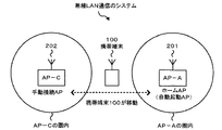
図1は、本発明の実施例に係る無線LAN通信のシステム図である。2個のアクセスポイントのAP201、AP202を例として示し、携帯端末100がこのAP間を移動する様子を示す。本発明の携帯端末100の内部には、予めユーザにより、自動起動対象AP(ホームAP)としてAP201(AP−A)が登録されているとする。携帯端末100は圏外においてもAP201に対するAPスキャンを行い、携帯端末100が移動してAP201(AP−A)圏内に入ると、携帯端末100は自動起動する。
FIG. 1 is a system diagram of wireless LAN communication according to an embodiment of the present invention. Two access points AP201 and AP202 are shown as an example, and the
また、携帯端末100がAP202(AP−C)のサービスエリア圏内に入って、ユーザにより手動接続により、AP202(AP−C)と手動で通信することができる。
In addition, the
次に、携帯端末100の内部構成について説明する。
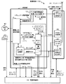
図2は、本発明の実施例に係る携帯端末100の関連部のブロック図である。携帯端末100は、制御部1、無線LANカード20(無線LAN通信部。無線LAN下位層)、アンテナ30、電源制御部40、表示部50、入力部60などから構成される。
Next, the internal configuration of the
FIG. 2 is a block diagram of relevant portions of the
[制御部1]
制御部1は、図示しないCPU、ROM、RAMなどから構成され、ROMに記憶されているソフトウェアに基づいて、無線LAN設定機能2、サスペンド起動処理機能10(スキャン対象AP制御手段)、データ送受信機能12(無線LAN通信の上位層)などを実行する。さらに、APリスト記憶部3、サスペンドタイマー11を有する。
[Control unit 1]
The
無線LAN設定機能2は、あと(図3、図4)で詳しく説明するが、入力部60のユーザ操作に基づいてAPのリスト登録、自動起動対象のホームAP登録を行い、APリスト記憶部3中にホームAPとして記録する。また、データ送受信機能12からの接続成功AP情報により、APリスト記憶部3中に接続中APとして記録する。また、ユーザ操作に基づき、自動起動のWOWの指示、手動接続指示などを行う。
As will be described in detail later (FIGS. 3 and 4), the wireless
無線LAN設定機能2は、手動接続の場合は、ユーザにより登録されたAPリスト記憶部3中のAPリストの複数のAPを、無線LANカードのスキャン対象AP記憶部24に順次書き込んで、無線LANカード20に無線LAN接続を行わせる。
In the case of manual connection, the wireless
無線LAN設定機能2は、自動起動のWOWを指示する場合は、自動起動対象のホームAPを、直接、無線LANカードのスキャン対象AP記憶部24に書き込むのではない。サスペンドタイマー11で周期的に起動されるサスペンド起動処理機能10が、状況を判断してダイナミックに、APリスト記憶部3の中のホームAP、又は、接続中APをスキャン対象AP記憶部24に書き込む。このサスペンド起動処理機能10については、あと(図5)で詳しく説明する。
The wireless
データ送受信機能12は、無線LAN通信の上位層であり、スキャンしたAPからのセキュリティ認証情報を出力する。また、無線LAN接続に成功したときに、当該成功したAPを接続成功APとして出力する。また、無線LAN通信の送受信終了情報を出力する。
The data transmission /
[無線LANカード20]
無線LANカード20は、無線LAN通信の下位層を処理する部分であり、データ通信部21、RSSI測定部22、APスキャン部23、スキャン対象AP記憶部24などを有する。アンテナ30は、無線LAN通信の図示しないアクセスポイントとの間で、無線信号の送受を行う。
[Wireless LAN card 20]
The
スキャン対象AP記憶部24は、アクセスポイントスキャンの対象となるアクセスポイント名を1個乃至複数個記憶する領域を有する。本発明では、制御部1は、スキャン対象AP記憶部24に対して、1個のアクセスポイント名のみを設定記録することで省電力を行う。
The scan target
RSSI測定部22は、アクセスポイントからの送信電波の受信電界強度を測定し、RSSI信号を制御部1のサスペンド起動処理機能10へ送出する。
The
APスキャン部23は、スキャン対象AP記憶部24に記録された1個乃至複数個のアクセスポイントに対してスキャンを行う。本発明では、1個しか記録されていないので、この1個のアクセスポイントに対してスキャンを行うことで省電力が図れる。この1個のアクセスポイントが検出できたら、対象AP検出信号を電源制御部40へ送出する。この対象AP検出信号は、携帯端末100全体を無線LAN通信可能な状態に起動するための信号として使われる。
The
データ通信部21は、APスキャン部23のスキャン検出後にアクティブとなって、スキャン以降のデータ通信処理を行う。
The
次に、無線LANカード20の消費電力状態について説明する。無線LANカード20は、電源制御部40からの停止/スキャン/アクティブ信号により制御されて、3つの状態、すなわち、消費電力がほぼ零で何も行わない停止状態と、低消費電力のスキャン状態と、全体が動作するアクティブ状態の3つの状態を取りうる。
Next, the power consumption state of the
停止状態は、無線LANを行わない場合に無線LANカード20に電源供給されない状態である。スキャン状態は、RSSI測定部22、APスキャン部23、スキャン対象AP記憶部24に電源供給されて、アクセスポイントに対してスキャンを行う状態である。スキャン対象AP記憶部24は不揮発性メモリである。このスキャン状態で動作するRSSI測定部22、APスキャン部23、スキャン対象AP記憶部24は共通のICチップ内に構成してもよい。アクティブ状態は、データ通信部21を含めた全体に電源供給されて、スキャン以降のデータ通信処理を行う状態である。
The stop state is a state in which power is not supplied to the
なお、各構成要素への電源供給を制御することで3つの状態を切り替えたが、各構成要素を禁止/許可するなどの方法で、3つの状態を切り替えてもよい。また、3つの状態に限らず、さらに構成要素毎に分けるような多くの状態を設けてもよい。
また、無線LANカード20は、カードでなくても、内蔵でもよい。
Although the three states are switched by controlling the power supply to each component, the three states may be switched by a method such as prohibiting / permitting each component. Moreover, you may provide not only three states but many states which divide | segment for every component.
The
無線LANカード20の停止/スキャン/アクティブ状態を制御する電源制御部40は常時動作可能である。
The power supply control unit 40 that controls the stop / scan / active state of the
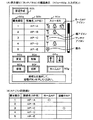
図3は、本発明の実施例に係る携帯端末100のAP登録設定を説明する図であり、(A)は表示部50の画面表示図、(B)は(A)に表示された各種AP情報を記憶するAPリスト記憶部3を説明する図である。
3A and 3B are diagrams for explaining AP registration setting of the
図3の(A)で、符号50番台は表示部、符号60番台はタッチパネル式の入力部である。表示部には、この例では、5個のアクセスポイントに関して、優先順位50a欄、接続名(AP名)50b欄、ステータス50c欄が表示される。
In FIG. 3A,
優先順位50a欄は、ユーザが無線LAN通信の手動起動を行った場合に、手動無線LAN起動機能5が優先順位50a欄の順番でアクセスポイントに接続しに行くものである。この優先順位50a欄は、予め、ユーザが無線LAN設定機能2により、任意の順番を設定するものである。
The
接続名(AP名)50b欄には、APリスト記憶部3(不揮発性メモリ)に記録された1乃至複数のアクセスポイント名(例えば、AP−A、AP−B、AP−C、AP−D、AP−Eの5個)が表示される。APリスト記憶部3へのAPの記録は、過去、無線LAN通信をおこなったAP履歴が記録されるようにしてもよいし、ユーザが手動で入力するようにしてもよい。
In the connection name (AP name) 50b column, one or more access point names (for example, AP-A, AP-B, AP-C, AP-D) recorded in the AP list storage unit 3 (nonvolatile memory) are displayed. , AP-E 5) is displayed. The AP record in the AP
ステータス50c欄には、各APのステータス情報が表示される。ホームAPアイコンは、複数のAPリスト中から、ユーザ操作により自動起動対象のAPとして選択されたAP−Aの欄に表示される。アンテナアイコンは、無線LANカード20からのRSSI信号に応じてアンテナマークが表示される。鍵アイコンは、APスキャンが行われて、APから送信されたセキュリティ認証情報に基づいて、鍵マークが表示される。鍵アイコンが表示されたAPとは無線LAN接続が拒否されており、パスワードがないと通信することができない。
The status information of each AP is displayed in the
図3の(B)は、APリスト記憶部3の内容を表し、図3の(A)で説明した優先順位50a、接続名(AP名)50b、ホームAP(AP−A)が記録される。また、無線LAN接続が成功した時のAPが、この例では、AP−Cが接続中APとして記録される。
FIG. 3B shows the contents of the AP
次に、図4により、無線LAN設定機能2の処理について、図3も用いて説明する。
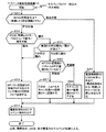
図4は、本発明の実施例に係る携帯端末100の無線LAN設定機能2の動作フローチャートである。ユーザが無線LAN通信モード操作を行うと、無線LAN設定機能2が起動する。
Next, the processing of the wireless
FIG. 4 is an operation flowchart of the wireless
無線LAN設定機能2は、まず、無線LAN−UI機能(ステップS1)が開始し、図3の(A)の画面表示を行う。そして、入力60a〜60gの押下チェックを行う(ステップS2)。カーソル60aの操作が行われると、5個のAP欄上でカーソル位置を上下させる(不図示)。
In the wireless
そして、ステップS2において、新規作成60bボタン/変更60cボタン/削除ボタン60dボタン操作に基づき、カーソル位置のAPに対して、接続名(AP名)50b欄の新規作成/変更/削除を行う(ステップS3)。これは、一般的に行われるUI操作であり、詳細を省略する。そして、APリスト記憶部3に優先順位、接続名(AP名)を記録する(ステップS4)。
In step S2, a new creation / change / deletion of the connection name (AP name) 50b column is performed for the AP at the cursor position based on the operation of the
ステップS2において、接続60eボタンの押下が検出されると、手動接続機能(ステップS10)が起動する。手動接続機能は、まず、優先順位50a欄の順番でAP名を、無線LANカード20のスキャン対象AP記憶部24に順次設定し、無線LAN手動開始信号を出力する(ステップS11)。これを受けて、電源制御部40は、無線LANカード20をアクティブ状態にし、無線LANカード20は、スキャンと接続処理を実行する。
In step S2, when the pressing of the
データ送受信機能12から接続成功AP信号を受信したら、例えば、それがAP−C名であれば、それをAPリスト記憶部3に、接続中APとして記録する(ステップS12)。
When a connection success AP signal is received from the data transmission /
また、APスキャン時の各APからのRSSIを、ステータス50c欄にアンテナアイコンとして表示する(ステップS13)。APスキャン時の各APからのセキュリティ認証情報により、ステータス50c欄に鍵アイコンを表示する(ステップS14)。この例では、AP−A、AP−B、AP−Dに鍵アイコンが表示され、パスワードがないと接続拒否される。
Further, the RSSI from each AP at the time of AP scan is displayed as an antenna icon in the
ステップS2において、ホームAP登録ボタン60gの押下が検出されると、その時点でカーソル表示されていたAP、この例では、AP−Aが自動起動対象のホームAPとして、AP−Aのステータス50c欄にホームAPアイコン表示を行う(ステップS5)。APリスト記憶部3に、AP−AをホームAPとして記録する(ステップS6)。
In step S2, when it is detected that the home
そして、自動起動機能(WOW)(ステップS20)が起動する。自動起動機能(WOW)は、WOW許可信号を出力する(ステップS21)。これを受けて、電源制御部40は、無線LANカード20をスキャン状態にし、制御部1をスリープ状態にする。
ただし、無線LAN設定機能2は、APリスト記憶部3にユーザ登録されたホームAP(AP−A)を、直接、無線LANカード20のスキャン対象AP記憶部24に記録することは行わない。APリスト記憶部3にユーザ登録されたホームAP(AP−A)を無線LANカード20のスキャン対象AP記憶部24に記録する処理は、サスペンド処理機能10が行う。
Then, the automatic activation function (WOW) (step S20) is activated. The automatic activation function (WOW) outputs a WOW permission signal (step S21). In response to this, the power supply control unit 40 puts the
However, the wireless
このサスペンド処理機能10について、次に説明する。
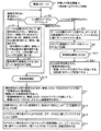
図5は、本発明の実施例に係る携帯端末100のサスペンド処理機能10の動作フローチャートである。サスペンド起動処理機能10は、サスペンドタイマー11からの定期的な、例えば5分周期のトリガ信号により、本来は、定期的に、稼動中(レジューム状態)の携帯端末を低消費電力のサスペンド状態にするための機能であるが、本発明では、それに加えて、無線LANカード20内のスキャン対象AP記憶部24へのダイナミックなAP設定を制御するスキャン対象AP制御手段として機能する。
The suspend processing function 10 will be described next.
FIG. 5 is an operation flowchart of the suspend processing function 10 of the
サスペンドタイマー11のトリガ信号およびサスペンド起動処理機能10は、携帯端末の各種状態とは無関係に非同期に発生し、アクセスポイントの圏内で発生することもあるし、圏外の状態で発生することもある。
The trigger signal of the suspend
サスペンド起動処理機能10は、サスペンドタイマー11により割込み起動されると、まず、無線LAN設定機能2からのWOWの許可信号をチェックする(ステップS51)。
When the suspend activation processing function 10 is interrupted and activated by the suspend
これが、WOW禁止状態であれば、無線LANカード20を動かす必要はないので、電源制御部40にWOW禁止を出す(ステップS59)。電源制御部40は、無線LANカード20を停止状態にする。
If this is the WOW prohibition state, it is not necessary to move the
ステップS51でWOW許可状態であれば、無線LANカード20からのRSSI信号により圏内/圏外判断を行う(ステップS52)。これが圏内であれば、APリスト記憶部3の接続中AP名をスキャン対象AP記憶部24に記録する(ステップS53)。
If it is in the WOW permission state in step S51, the inside / outside area determination is performed based on the RSSI signal from the wireless LAN card 20 (step S52). If this is within the range, the connected AP name of the AP
ステップS52で圏外であれば、APサービスエリア周縁部でのバタつきを考慮して、前回5分前の圏内/圏外状態がどうであったか記憶するフラグ(不図示)をチェックする(ステップS55)。これが、前回5分前は圏内だったのであれば、完全な圏外にはまだなっていないと判断して、圏内と同じ処理の前述のステップS53に入る。前回5分前も圏外であれば完全な圏外と判断して、ユーザ登録のAPリスト記憶部3に自動起動対象のホームAPが登録されているかをチェックする(ステップS56)。登録されていれば、このホームAPを、無線LANカード20内のスキャン対象AP記憶部24に記録する(ステップS57)。ステップS56で登録されていなければ、スキャン対象AP記憶部24をクリアする。
If it is out of the service area in step S52, a flag (not shown) for storing the state of the service area / out of
すなわち、サスペンド起動処理機能10は、所定周期で定期的に起動されるので、その度に、圏内圏外チェックを行い、圏内では、現在接続中の接続中APを、無線LANカード20内のスキャン対象AP記憶部24に記録し、圏外では、無線LAN通信中ではないので、ユーザ登録のホームAPを無線LANカード20内のスキャン対象AP記憶部24に記録する。
That is, since the suspend activation processing function 10 is periodically activated at a predetermined cycle, a check is made outside the service area each time, and in the service area, the currently connected AP that is currently connected is scanned within the
これにより、実際にスキャンを行う無線LANカード20内のスキャン対象AP記憶部24に対して、ユーザ登録のホームAPと、手動接続などで接続中の接続中APとがダイナミックに切替えることができる。
As a result, the home AP registered as a user and the connecting AP currently connected by manual connection or the like can be dynamically switched with respect to the scan target
従来は、ユーザ登録のWOW用のホームAPはUIにより直接無線LANカード20内のスキャン対象AP記憶部24に書き込まれていたので、これを手動接続時に、他のAPに切替えると、再度、WOW用設定に戻すためには、UIで再登録が必要となってしまっていた。
Conventionally, the home AP for WOW registered as a user has been directly written in the scan target
以上のステップS53、S57、S58、S59の処理で、無線LANカード20内のスキャン対象AP記憶部24に対する制御を行い、その後、最後に、本来のサスペンド処理であるサスペンドへの移行を指示するために、電源制御部40にサスペンド指示を出し(ステップS54)、終了する。それを受けて、電源制御部40は、携帯端末100を低消費電力のサスペンド状態にする。
In the processes of steps S53, S57, S58, and S59 described above, the scan target
サスペンド起動処理機能10は、本来、定期的に動作する機能であり、定期的に動作することにより、本発明の、圏内圏外状態をチェックすることができ、それにより、無線LANカード20内のスキャン対象AP記憶部24へのダイナミックなAP設定を制御することができるものである。
The suspend activation processing function 10 is originally a function that operates periodically, and by operating periodically, it is possible to check the out-of-service state of the present invention, thereby scanning within the
なお、ステップS55で前回5分前の圏内/圏外状態がどうであったかをチェックしたが、この処理は削除して、ステップS52の圏外から直接にステップS56に入るようにしてもよい。 In step S55, it was checked how the range / out-of-range state was 5 minutes before, but this processing may be deleted and step S56 may be entered directly from outside the range in step S52.
以上説明した処理により、図1において、携帯端末100が、ユーザ登録の自動起動対象のホームAP圏内、他の手動接続対象AP圏内、両APの圏外の領域を移動した場合に、どのように動作するかを説明する。
ユーザは、予め、APリスト記憶部6にホームAPとしてAP−Aを登録してあるものとする。また、携帯端末100が電源オンになった直後、APリスト記憶部6内のホームAP(AP−A)を無線LANカード20のスキャン対象AP記憶部24にデフォルト設定しておくものとする。
With the processing described above, how the
It is assumed that the user has previously registered AP-A as the home AP in the AP
携帯端末100がAP−A圏内で電源オンになると、スキャン対象AP記憶部24に記録されているAP−Aに対して、WOWが起動し、AP−Aがスキャンで検出されて、携帯端末100全体が自動起動する。
When the
携帯端末100が圏外エリアに移動すると、サスペンド起動処理機能10により、ホームAP(AP−A)が無線LANカード20内のスキャン対象AP記憶部24に記録され、無線LANカード20は、ホームAP(AP−A)に対するスキャンを行う。当然、ホームAP(AP−A)を検出することはできない。
When the
携帯端末100がAP−C圏内に入り、ユーザが、無線LAN通信を手動で行うと、APリスト記憶部3の優先度順で無線LAN接続が行われ、結果として、AP−Cと接続される。そして、AP−C名が、APリスト記憶部3に接続中APとして記録される。
When the
サスペンド起動処理機能10は定期的に発生しており、このAP−C圏内で度々発生すると、サスペンド起動処理機能10は、圏内を検出し、APリスト記憶部3の接続中AP(AP−C)をスキャン対象AP記憶部24に記録し、AP−Cとの間の通信が継続される。
The suspend activation processing function 10 is periodically generated. When the suspend activation processing function 10 is frequently generated in the AP-C area, the suspend activation processing function 10 detects the area and the connected AP (AP-C) in the AP
その後、携帯端末100が圏外エリアに移動すると、上記圏外エリアでの処理を行う。
Thereafter, when the
本発明によれば、無線LANカード20が行うスキャン対象のAPを1個とすることにより、スキャンに伴う消費電力を低減する。そして、1個としたことによるユーザ利便性の低下を、所定の周期毎に起動されるサスペンド起動処理機能10により、圏外中に、ユーザ設定のホームAPが再度、無線LANカード20内のスキャン対象AP記憶部に記録されるので、ユーザによるホームAP登録をやり直す必要がなく、利便性が向上する。
According to the present invention, the number of APs to be scanned by the
次に、電源制御部40の機能について説明する。
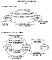
図6は、本発明の実施例に係る携帯端末100の電源制御部40が他のブロックの消費電力状態を制御する状態遷移図である。図2も用いて、電源制御部40の動作を説明する。本発明の主要部分ではないので、簡単に説明する。図2の電源制御部40の入出力信号、および図6には、全ての遷移要因を図示していない。
Next, functions of the power supply control unit 40 will be described.
FIG. 6 is a state transition diagram in which the power control unit 40 of the
図6の(A)は、電源制御部40が制御部1のスリープ状態とアクティブ状態の2つの状態を切り替える状態遷移図である。
FIG. 6A is a state transition diagram in which the power supply control unit 40 switches between two states of the
電源制御部40が制御部1のスリープ状態をアクティブ状態へと遷移させる要因の1つは、入力部60からの「操作あり」信号であり、入力部60に関連の無線LAN設定機能2が動けるようになる。要因の2つ目は、サスペンドタイマー11からの所定周期毎に発生するトリガ信号であり、関連のサスペンド起動処理機能10が動けるようになる。要因の3つ目は、APスキャン部23からの対象AP検出信号であり、対象APをスキャンして検出したあとの無線LAN上位層の処理を行うデータ送受信を行うデータ送受信機能12が動けるようになる。
One of the factors that cause the power supply control unit 40 to transition the sleep state of the
電源制御部40が制御部1のアクティブ状態からスリープ状態へと逆に遷移させる要因は、サスペンド起動処理機能10からのサスペンド指示信号であり、所定周期毎にスリープ状態へと遷移させる。
The factor that causes the power supply control unit 40 to reversely transition from the active state of the
図6の(B)は、電源制御部40が無線LANカード20の停止状態とスキャン状態とアクティブ状態の3つの状態を切り替える状態遷移図である。 FIG. 6B is a state transition diagram in which the power supply control unit 40 switches between three states of the wireless LAN card 20: a stopped state, a scan state, and an active state.
電源制御部40が無線LANカード20の停止状態からスキャン状態へと遷移させる要因の1つは、無線LAN設定機能2からのWOW設定許可信号であり、Wake On Wireless LANのために、無線LANカード20のスキャン動作が動ける状態になる。要因の2つ目は、無線LAN設定機能2からのWOW禁止であり、例えば、ユーザがホームAP登録を削除した場合などである。
One of the factors that cause the power supply control unit 40 to transition from the stop state to the scan state of the
電源制御部40が無線LANカード20のスキャン状態から停止状態へと逆に遷移させる要因の1つ目は、無線LAN設定機能2からのWOW禁止であり、無線LANカード20が停止する。要因の2つ目は、サスペンド起動処理機能10からのWOW禁止であり、本来のサスペンド起動のための信号である。
The first factor causing the power supply control unit 40 to reversely transition from the scan state to the stop state of the
電源制御部40が無線LANカード20のスキャン状態からアクティブ状態へと遷移させる要因は、APスキャン部23からの対象AP検出信号であり、無線LANカード20全体が動けるようになる。
The factor causing the power supply control unit 40 to transition from the scan state of the
電源制御部40が無線LANカード20のアクティブ状態からスキャン状態へと逆に遷移させる要因は、データ送受信機能12からの送受信終了信号であり、スキャン状態へと戻る。
The factor that causes the power supply control unit 40 to reversely transition from the active state to the scan state of the
なお、本発明の実施例においては、所定の周期毎に起動されるサスペンド起動処理機能10により、上記処理を行ったが、例えば、手動無線LAN起動機能5が、手動で起動した無線LAN通信の終了をチェックして、終了時に、APリスト記憶部3のホームAPをスキャン対象AP記憶部24に記録するようにしてもよい。
In the embodiment of the present invention, the above-described processing is performed by the suspend activation processing function 10 activated at predetermined intervals. For example, the manual wireless
また、無線LANカード20内のスキャン対象AP記憶部24には、1個のAPのみ記録することで省電力化したが、ユーザの利便性を考えて、2個を自動起動のスキャン対象として、その内の1個に対して、手動接続のAPを切替えるようにしてもよい。
In addition, the scan target
また、無線LANカード20内のAPスキャン部23は、スキャン対象AP記憶部24に記録してあるAP全てに対して、無条件でスキャンしてしまうが、これと別に、第2のスキャン対象AP記憶部を設けて、第1のスキャン対象AP記憶部24には、WOW用にAPを登録し、第2のスキャン対象AP記憶部には、手動接続用のAPを登録し、制御部1が無線LANカード20に対して、どちらのスキャン対象AP記憶部を使用するかを指示するようにしてもよい。
In addition, the
1 制御部
2 無線LAN設定機能
3 APリスト記憶部
10 サスペンド起動処理機能(スキャン対象AP制御手段)
11 サスペンドタイマー
12 データ送受信機能
20 無線LANカード20(無線LAN通信部)
21 データ通信部
22 RSSI測定部
23 APスキャン部
24 スキャン対象AP記憶部
30 アンテナ
40 電源制御部
50 表示部
60 入力部
100 携帯端末
201、202 AP(アクセスポイント)
DESCRIPTION OF
11 Suspend
21
Claims (5)
前記無線LAN通信部は、
スキャン対象のアクセスポイントが記録されるスキャン対象アクセスポイント記憶部と、
前記スキャン対象アクセスポイント記憶部に記録されているアクセスポイントに対するスキャンを行って、当該アクセスポイントを検出するアクセスポイントスキャン部と
を有し、
前記制御部は、
自動起動対象のホームアクセスポイントが記録されるホームアクセスポイント記憶部と、
前記無線LAN通信部に前記スキャンを指示する自動起動制御手段と、
アクセスポイントが記録されるアクセスポイントリスト記憶部と、
アクセスポイントと接続成功した場合の当該アクセスポイントを記録する接続中アクセスポイント記憶部と、
前記アクセスポイントリスト記憶部のアクセスポイントを前記スキャン対象アクセスポイント記憶部に書き込んで、前記無線LAN通信部に前記スキャンを指示し、接続したアクセスポイントを前記接続中アクセスポイント記憶部に記録する手動接続制御部と、
無線LAN通信を行っていないときは、前記ホームアクセスポイント記憶部のホームアクセスポイントを前記スキャン対象アクセスポイント記憶部に書き込み、無線LAN通信中のときは、前記接続中アクセスポイント記憶部のアクセスポイントを前記スキャン対象アクセスポイント記憶部に書き込むスキャン対象アクセスポイント制御手段と
を有することを特徴とする携帯端末。 A portable terminal having a wireless LAN communication unit and a control unit,
The wireless LAN communication unit
A scan target access point storage unit in which a scan target access point is recorded;
An access point scan unit that performs a scan on an access point recorded in the scan target access point storage unit and detects the access point;
The controller is
A home access point storage unit in which home access points to be automatically started are recorded;
Automatic start control means for instructing the scanning to the wireless LAN communication unit;
An access point list storage unit in which access points are recorded;
A connected access point storage unit that records the access point when the connection with the access point is successful;
Manual connection that writes the access point of the access point list storage unit to the scan target access point storage unit, instructs the wireless LAN communication unit to perform the scan, and records the connected access point in the connected access point storage unit A control unit;
When wireless LAN communication is not performed, the home access point of the home access point storage unit is written into the scan target access point storage unit, and when wireless LAN communication is being performed, the access point of the connected access point storage unit is A portable terminal comprising: a scan target access point control unit that writes in the scan target access point storage unit.
前記無線LAN通信部は、
スキャン対象のアクセスポイントが記録されるスキャン対象アクセスポイント記憶部と、
前記スキャン対象アクセスポイント記憶部に記録されているアクセスポイントに対するスキャンを行って、当該アクセスポイントを検出するアクセスポイントスキャン部と、
アクセスポイントからの送信電波の受信電界強度を測定して、受信電界強度信号を前記スキャン対象アクセスポイント制御手段へ出力する受信電界強度測定部とを有し、
前記制御部は、
自動起動対象のホームアクセスポイントが記録されるホームアクセスポイント記憶部と、
前記無線LAN通信部に前記スキャンを指示する自動起動制御手段と、
アクセスポイントが記録されるアクセスポイントリスト記憶部と、
アクセスポイントと接続成功した場合の当該アクセスポイントを記録する接続中アクセスポイント記憶部と、
携帯端末を低消費電力状態であるサスペンド状態に所定周期毎に起動するタイミング信号を発生するタイマーと、
前記タイマーにより所定周期毎に起動されて、前記受信電界強度信号が判定閾値に対して圏外状態であれば、前記ホームアクセスポイント記憶部のホームアクセスポイントを前記スキャン対象アクセスポイント記憶部に書き込み、前記受信電界強度信号が判定閾値に対して圏内状態であれば、前記接続中アクセスポイント記憶部のアクセスポイントを前記スキャン対象アクセスポイント記憶部に書き込むスキャン対象アクセスポイント制御手段と
を有することを特徴とする携帯端末。 A portable terminal having a wireless LAN communication unit and a control unit,
The wireless LAN communication unit
A scan target access point storage unit in which a scan target access point is recorded;
An access point scanning unit that scans an access point recorded in the scan target access point storage unit and detects the access point;
A reception field strength measurement unit that measures the reception field strength of the transmission radio wave from the access point and outputs a reception field strength signal to the scan target access point control means;
The controller is
A home access point storage unit in which home access points to be automatically started are recorded;
Automatic start control means for instructing the scanning to the wireless LAN communication unit;
An access point list storage unit in which access points are recorded;
A connected access point storage unit that records the access point when the connection with the access point is successful;
A timer that generates a timing signal for starting the mobile terminal in a suspended state, which is a low power consumption state, at predetermined intervals;
When the reception electric field strength signal is activated at predetermined intervals by the timer and the received electric field strength signal is out of range with respect to a determination threshold, the home access point of the home access point storage unit is written to the scan target access point storage unit, Scanning access point control means for writing the access point of the connected access point storage unit into the scan target access point storage unit when the received electric field strength signal is within a range with respect to the determination threshold value Mobile device.
前記手動接続制御部は、前記アクセスポイントリスト記憶部の複数のアクセスポイントを前記優先度順に前記スキャン対象アクセスポイント記憶部に書き込んで、前記無線LAN通信部に前記スキャンを指示する
ことを特徴とする請求項1記載の携帯端末。 In the access point list storage unit, one or a plurality of access points are designated and recorded by a user operation input,
The manual connection control unit writes a plurality of access points of the access point list storage unit into the scan target access point storage unit in order of priority, and instructs the wireless LAN communication unit to perform the scan. The mobile terminal according to claim 1.
さらに、
前記アクセスポイントスキャン部がアクセスポイントを検出したとき、携帯端末を稼動状態であるレジューム状態にし、前記スキャン対象アクセスポイント制御手段からサスペンド指示信号を受けたとき、携帯端末をサスペンド状態にする電源制御部を
有することを特徴とする請求項2記載の携帯端末。 The scan target access point control means further outputs a suspend instruction signal for putting the mobile terminal in a suspend state, which is a low power consumption state,
further,
When the access point scanning unit detects an access point, the power supply control unit puts the mobile terminal in a resume state in which the mobile terminal is in operation, and puts the mobile terminal in a suspend state when receiving a suspend instruction signal from the scan target access point control means The mobile terminal according to claim 2, further comprising:
Priority Applications (2)
| Application Number | Priority Date | Filing Date | Title |
|---|---|---|---|
| JP2009126928A JP4834754B2 (en) | 2009-05-26 | 2009-05-26 | Mobile device |
| US12/723,804 US20100303040A1 (en) | 2009-05-26 | 2010-03-15 | Mobile communication terminal |
Applications Claiming Priority (1)
| Application Number | Priority Date | Filing Date | Title |
|---|---|---|---|
| JP2009126928A JP4834754B2 (en) | 2009-05-26 | 2009-05-26 | Mobile device |
Related Child Applications (1)
| Application Number | Title | Priority Date | Filing Date |
|---|---|---|---|
| JP2011206818A Division JP2012034394A (en) | 2011-09-22 | 2011-09-22 | Portable terminal and communication control method |
Publications (3)
| Publication Number | Publication Date |
|---|---|
| JP2010278564A true JP2010278564A (en) | 2010-12-09 |
| JP2010278564A5 JP2010278564A5 (en) | 2011-06-23 |
| JP4834754B2 JP4834754B2 (en) | 2011-12-14 |
Family
ID=43220144
Family Applications (1)
| Application Number | Title | Priority Date | Filing Date |
|---|---|---|---|
| JP2009126928A Expired - Fee Related JP4834754B2 (en) | 2009-05-26 | 2009-05-26 | Mobile device |
Country Status (2)
| Country | Link |
|---|---|
| US (1) | US20100303040A1 (en) |
| JP (1) | JP4834754B2 (en) |
Cited By (4)
| Publication number | Priority date | Publication date | Assignee | Title |
|---|---|---|---|---|
| JP2014179719A (en) * | 2013-03-14 | 2014-09-25 | Buffalo Inc | Radio communication device, method for determining priority order of use access point, program and recording medium |
| WO2014184879A1 (en) | 2013-05-14 | 2014-11-20 | 富士通株式会社 | Mobile information processing device, information processing system, and information processing method |
| JP2016022347A (en) * | 2014-07-24 | 2016-02-08 | シャープ株式会社 | Washing machine |
| JP2017010298A (en) * | 2015-06-23 | 2017-01-12 | 三菱電機株式会社 | Maintenance and inspection support system |
Families Citing this family (11)
| Publication number | Priority date | Publication date | Assignee | Title |
|---|---|---|---|---|
| JP4309932B2 (en) * | 2007-04-16 | 2009-08-05 | 株式会社エヌ・ティ・ティ・ドコモ | Communication terminal and search method |
| US8971244B2 (en) * | 2010-11-09 | 2015-03-03 | Qualcomm Incorporated | Access point name list based network access management |
| JP5761993B2 (en) * | 2010-12-28 | 2015-08-12 | キヤノン株式会社 | Access point search apparatus, access point search method, and program |
| KR20130099532A (en) * | 2012-02-29 | 2013-09-06 | 주식회사 팬택 | Terminal and method for determining priority of connection wiht wifi access point |
| JP5865795B2 (en) * | 2012-07-13 | 2016-02-17 | 株式会社Nttドコモ | Mobile communication terminal, server device, detection operation control system, detection operation control method, and program |
| WO2014033887A1 (en) * | 2012-08-30 | 2014-03-06 | 富士通株式会社 | Mobile terminal apparatus, control method and control program |
| CN106332252A (en) * | 2015-07-07 | 2017-01-11 | 手持产品公司 | WIFI enablement based on unit signal |
| CN109275173A (en) * | 2017-07-17 | 2019-01-25 | 中创通信技术(深圳)有限公司 | A kind of method, apparatus connected by force using WIFI and electronic equipment |
| JP6991765B2 (en) * | 2017-07-25 | 2022-01-13 | キヤノン株式会社 | Information processing equipment, its control method, and programs |
| US12381642B2 (en) * | 2021-12-28 | 2025-08-05 | GE Precision Healthcare LLC | Setting and dynamically adjusting a hysteresis value used to control roaming of a wireless monitoring system |
| US12200612B2 (en) * | 2022-01-18 | 2025-01-14 | GE Precision Healthcare LLC | Methods and systems for conditional scanning |
Citations (6)
| Publication number | Priority date | Publication date | Assignee | Title |
|---|---|---|---|---|
| JP2000175259A (en) * | 1998-12-02 | 2000-06-23 | Kenwood Corp | Standby control system for mobile telephone set |
| JP2002354532A (en) * | 2001-05-28 | 2002-12-06 | Ntt Docomo Inc | Frequency search method in mobile station and mobile station |
| JP2004023391A (en) * | 2002-06-14 | 2004-01-22 | Nec Corp | Mobile telephone set and communication method in mobile telephone set |
| JP2007513547A (en) * | 2003-11-19 | 2007-05-24 | モトローラ・インコーポレイテッド | Home network search during roaming in wireless communication network |
| JP2007325064A (en) * | 2006-06-02 | 2007-12-13 | Nagano Japan Radio Co | Wireless LAN handover method |
| JP2008288727A (en) * | 2007-05-15 | 2008-11-27 | Sony Ericsson Mobilecommunications Japan Inc | Radio communication method, radio communication terminal and radio communication program |
Family Cites Families (2)
| Publication number | Priority date | Publication date | Assignee | Title |
|---|---|---|---|---|
| JP3792154B2 (en) * | 2001-12-26 | 2006-07-05 | インターナショナル・ビジネス・マシーンズ・コーポレーション | Network security system, computer apparatus, access point recognition processing method, access point check method, program, and storage medium |
| US20070147317A1 (en) * | 2005-12-23 | 2007-06-28 | Motorola, Inc. | Method and system for providing differentiated network service in WLAN |
-
2009
- 2009-05-26 JP JP2009126928A patent/JP4834754B2/en not_active Expired - Fee Related
-
2010
- 2010-03-15 US US12/723,804 patent/US20100303040A1/en not_active Abandoned
Patent Citations (6)
| Publication number | Priority date | Publication date | Assignee | Title |
|---|---|---|---|---|
| JP2000175259A (en) * | 1998-12-02 | 2000-06-23 | Kenwood Corp | Standby control system for mobile telephone set |
| JP2002354532A (en) * | 2001-05-28 | 2002-12-06 | Ntt Docomo Inc | Frequency search method in mobile station and mobile station |
| JP2004023391A (en) * | 2002-06-14 | 2004-01-22 | Nec Corp | Mobile telephone set and communication method in mobile telephone set |
| JP2007513547A (en) * | 2003-11-19 | 2007-05-24 | モトローラ・インコーポレイテッド | Home network search during roaming in wireless communication network |
| JP2007325064A (en) * | 2006-06-02 | 2007-12-13 | Nagano Japan Radio Co | Wireless LAN handover method |
| JP2008288727A (en) * | 2007-05-15 | 2008-11-27 | Sony Ericsson Mobilecommunications Japan Inc | Radio communication method, radio communication terminal and radio communication program |
Cited By (5)
| Publication number | Priority date | Publication date | Assignee | Title |
|---|---|---|---|---|
| JP2014179719A (en) * | 2013-03-14 | 2014-09-25 | Buffalo Inc | Radio communication device, method for determining priority order of use access point, program and recording medium |
| WO2014184879A1 (en) | 2013-05-14 | 2014-11-20 | 富士通株式会社 | Mobile information processing device, information processing system, and information processing method |
| US10111046B2 (en) | 2013-05-14 | 2018-10-23 | Fujitsu Limited | Portable type information processing apparatus, information processing system, and information processing method |
| JP2016022347A (en) * | 2014-07-24 | 2016-02-08 | シャープ株式会社 | Washing machine |
| JP2017010298A (en) * | 2015-06-23 | 2017-01-12 | 三菱電機株式会社 | Maintenance and inspection support system |
Also Published As
| Publication number | Publication date |
|---|---|
| US20100303040A1 (en) | 2010-12-02 |
| JP4834754B2 (en) | 2011-12-14 |
Similar Documents
| Publication | Publication Date | Title |
|---|---|---|
| JP4834754B2 (en) | Mobile device | |
| EP3101958B1 (en) | Mobile terminal and method for controlling the same | |
| EP2602981B1 (en) | Hand-held mobile terminal standby method, micro processor and cellular phone thereof | |
| US9071970B2 (en) | Terminal device | |
| US20180302792A1 (en) | Network connection method and apparatus, and computer storage medium | |
| US20110281556A1 (en) | System of wi-fi terminals and channel operation method for the same | |
| KR20130068250A (en) | Apparatas and method of user based using for grip sensor in a portable terminal | |
| JP2014071488A (en) | Function execution device | |
| US10298737B2 (en) | Portable terminal apparatus | |
| KR20100083960A (en) | Power saving method of portable device and portable device supporting the same | |
| CN105933742A (en) | Remote control terminal and method for paring same with primary device | |
| US20200015064A1 (en) | Wireless Communication Connection Method and Terminal | |
| US20120327849A1 (en) | Method for controlling network connection of wireless network device and associated wireless network device | |
| US20200260374A1 (en) | Method and apparatus for scanning access points in a portable terminal | |
| JP2012034394A (en) | Portable terminal and communication control method | |
| JP2008061111A (en) | Electronic device and wireless communication control method | |
| CN105338527A (en) | Network access configuration method and system for Internet of Things module | |
| CN112911560A (en) | Electronic business card transmission method and device | |
| CN109918014B (en) | Page display method, wearable device and computer-readable storage medium | |
| CN113596967A (en) | WIFI dormancy control method and device for MIFI equipment, computer equipment and storage medium | |
| CN106507357B (en) | Access control method and terminal equipment | |
| US20150223225A1 (en) | Portable communication device and communication control method | |
| US20150163737A1 (en) | Method and device for controlling turn-on and turn-off of wireless network | |
| JP2019126100A (en) | Radio communication device, radio communication method, and program | |
| US10110720B2 (en) | Dialing method for user terminal and user terminal |
Legal Events
| Date | Code | Title | Description |
|---|---|---|---|
| A521 | Request for written amendment filed |
Free format text: JAPANESE INTERMEDIATE CODE: A523 Effective date: 20110415 |
|
| A621 | Written request for application examination |
Free format text: JAPANESE INTERMEDIATE CODE: A621 Effective date: 20110415 |
|
| A871 | Explanation of circumstances concerning accelerated examination |
Free format text: JAPANESE INTERMEDIATE CODE: A871 Effective date: 20110415 |
|
| RD03 | Notification of appointment of power of attorney |
Free format text: JAPANESE INTERMEDIATE CODE: A7423 Effective date: 20110415 |
|
| A521 | Request for written amendment filed |
Free format text: JAPANESE INTERMEDIATE CODE: A821 Effective date: 20110415 |
|
| A975 | Report on accelerated examination |
Free format text: JAPANESE INTERMEDIATE CODE: A971005 Effective date: 20110524 |
|
| A131 | Notification of reasons for refusal |
Free format text: JAPANESE INTERMEDIATE CODE: A131 Effective date: 20110621 |
|
| A521 | Request for written amendment filed |
Free format text: JAPANESE INTERMEDIATE CODE: A523 Effective date: 20110815 |
|
| TRDD | Decision of grant or rejection written | ||
| A01 | Written decision to grant a patent or to grant a registration (utility model) |
Free format text: JAPANESE INTERMEDIATE CODE: A01 Effective date: 20110830 |
|
| A01 | Written decision to grant a patent or to grant a registration (utility model) |
Free format text: JAPANESE INTERMEDIATE CODE: A01 |
|
| A61 | First payment of annual fees (during grant procedure) |
Free format text: JAPANESE INTERMEDIATE CODE: A61 Effective date: 20110926 |
|
| FPAY | Renewal fee payment (event date is renewal date of database) |
Free format text: PAYMENT UNTIL: 20140930 Year of fee payment: 3 |
|
| LAPS | Cancellation because of no payment of annual fees |