JP2010260102A - Beam welding process using vented shim - Google Patents
Beam welding process using vented shim Download PDFInfo
- Publication number
- JP2010260102A JP2010260102A JP2010102872A JP2010102872A JP2010260102A JP 2010260102 A JP2010260102 A JP 2010260102A JP 2010102872 A JP2010102872 A JP 2010102872A JP 2010102872 A JP2010102872 A JP 2010102872A JP 2010260102 A JP2010260102 A JP 2010260102A
- Authority
- JP
- Japan
- Prior art keywords
- shim
- inclined edge
- beam welding
- welding
- vent path
- Prior art date
- Legal status (The legal status is an assumption and is not a legal conclusion. Google has not performed a legal analysis and makes no representation as to the accuracy of the status listed.)
- Granted
Links
- 238000003466 welding Methods 0.000 title claims abstract description 50
- 238000000034 method Methods 0.000 title claims abstract description 31
- 239000007769 metal material Substances 0.000 claims description 42
- 230000000295 complement effect Effects 0.000 claims description 16
- 238000010894 electron beam technology Methods 0.000 claims description 4
- 239000002184 metal Substances 0.000 abstract description 12
- 239000000463 material Substances 0.000 description 7
- HSFWRNGVRCDJHI-UHFFFAOYSA-N Acetylene Chemical compound C#C HSFWRNGVRCDJHI-UHFFFAOYSA-N 0.000 description 2
- 230000015572 biosynthetic process Effects 0.000 description 2
- 238000012986 modification Methods 0.000 description 2
- 230000004048 modification Effects 0.000 description 2
- 230000009286 beneficial effect Effects 0.000 description 1
- 238000010943 off-gassing Methods 0.000 description 1
Images


Classifications
-
- B—PERFORMING OPERATIONS; TRANSPORTING
- B23—MACHINE TOOLS; METAL-WORKING NOT OTHERWISE PROVIDED FOR
- B23K—SOLDERING OR UNSOLDERING; WELDING; CLADDING OR PLATING BY SOLDERING OR WELDING; CUTTING BY APPLYING HEAT LOCALLY, e.g. FLAME CUTTING; WORKING BY LASER BEAM
- B23K26/00—Working by laser beam, e.g. welding, cutting or boring
- B23K26/20—Bonding
- B23K26/21—Bonding by welding
- B23K26/24—Seam welding
- B23K26/26—Seam welding of rectilinear seams
-
- B—PERFORMING OPERATIONS; TRANSPORTING
- B23—MACHINE TOOLS; METAL-WORKING NOT OTHERWISE PROVIDED FOR
- B23K—SOLDERING OR UNSOLDERING; WELDING; CLADDING OR PLATING BY SOLDERING OR WELDING; CUTTING BY APPLYING HEAT LOCALLY, e.g. FLAME CUTTING; WORKING BY LASER BEAM
- B23K15/00—Electron-beam welding or cutting
- B23K15/0046—Welding
- B23K15/0053—Seam welding
- B23K15/006—Seam welding of rectilinear seams
-
- B—PERFORMING OPERATIONS; TRANSPORTING
- B23—MACHINE TOOLS; METAL-WORKING NOT OTHERWISE PROVIDED FOR
- B23K—SOLDERING OR UNSOLDERING; WELDING; CLADDING OR PLATING BY SOLDERING OR WELDING; CUTTING BY APPLYING HEAT LOCALLY, e.g. FLAME CUTTING; WORKING BY LASER BEAM
- B23K15/00—Electron-beam welding or cutting
- B23K15/0046—Welding
- B23K15/0053—Seam welding
- B23K15/0073—Seam welding with interposition of particular material to facilitate connecting the parts, e.g. using a filler
-
- B—PERFORMING OPERATIONS; TRANSPORTING
- B23—MACHINE TOOLS; METAL-WORKING NOT OTHERWISE PROVIDED FOR
- B23K—SOLDERING OR UNSOLDERING; WELDING; CLADDING OR PLATING BY SOLDERING OR WELDING; CUTTING BY APPLYING HEAT LOCALLY, e.g. FLAME CUTTING; WORKING BY LASER BEAM
- B23K15/00—Electron-beam welding or cutting
- B23K15/0046—Welding
- B23K15/0093—Welding characterised by the properties of the materials to be welded
-
- B—PERFORMING OPERATIONS; TRANSPORTING
- B23—MACHINE TOOLS; METAL-WORKING NOT OTHERWISE PROVIDED FOR
- B23K—SOLDERING OR UNSOLDERING; WELDING; CLADDING OR PLATING BY SOLDERING OR WELDING; CUTTING BY APPLYING HEAT LOCALLY, e.g. FLAME CUTTING; WORKING BY LASER BEAM
- B23K26/00—Working by laser beam, e.g. welding, cutting or boring
- B23K26/20—Bonding
- B23K26/21—Bonding by welding
- B23K26/211—Bonding by welding with interposition of special material to facilitate connection of the parts
-
- B—PERFORMING OPERATIONS; TRANSPORTING
- B23—MACHINE TOOLS; METAL-WORKING NOT OTHERWISE PROVIDED FOR
- B23K—SOLDERING OR UNSOLDERING; WELDING; CLADDING OR PLATING BY SOLDERING OR WELDING; CUTTING BY APPLYING HEAT LOCALLY, e.g. FLAME CUTTING; WORKING BY LASER BEAM
- B23K2101/00—Articles made by soldering, welding or cutting
- B23K2101/18—Sheet panels
-
- F—MECHANICAL ENGINEERING; LIGHTING; HEATING; WEAPONS; BLASTING
- F16—ENGINEERING ELEMENTS AND UNITS; GENERAL MEASURES FOR PRODUCING AND MAINTAINING EFFECTIVE FUNCTIONING OF MACHINES OR INSTALLATIONS; THERMAL INSULATION IN GENERAL
- F16B—DEVICES FOR FASTENING OR SECURING CONSTRUCTIONAL ELEMENTS OR MACHINE PARTS TOGETHER, e.g. NAILS, BOLTS, CIRCLIPS, CLAMPS, CLIPS OR WEDGES; JOINTS OR JOINTING
- F16B5/00—Joining sheets or plates, e.g. panels, to one another or to strips or bars parallel to them
- F16B5/08—Joining sheets or plates, e.g. panels, to one another or to strips or bars parallel to them by means of welds or the like
Landscapes
- Engineering & Computer Science (AREA)
- Mechanical Engineering (AREA)
- Physics & Mathematics (AREA)
- Optics & Photonics (AREA)
- Plasma & Fusion (AREA)
- Chemical & Material Sciences (AREA)
- Materials Engineering (AREA)
- Welding Or Cutting Using Electron Beams (AREA)
- Laser Beam Processing (AREA)
Abstract
Description
本発明は広義には溶接に関し、具体的には、ベント式シムビーム溶接プロセスに関する。 The present invention relates generally to welding and, more particularly, to a vented shim beam welding process.
材料をビーム溶接する際に、溶接プロセス中に発生したガスが溶融池から逃れるメカニズムがないと、ポロシティを含む溶接部を生じかねない。ポロシティを含む溶接部の形成は、厚い材料片を接合する場合に起こる可能性が高まる。材料片が厚いほど、溶接プロセス中に発生して逃散することができず、ポロシティを含む溶接部を生じるガスが溶接時に形成される可能性が大きい。 When beam welding materials, the lack of a mechanism for the gas generated during the welding process to escape the weld pool can result in welds containing porosity. The formation of welds containing porosity increases the likelihood that they will occur when joining thick pieces of material. The thicker the piece of material, the more likely it will be that it will be generated and escaped during the welding process, and a gas will be formed during welding that will result in welds containing porosity.
図1に、シム104を用いて2つの材料部材102を溶接する従来技術の方法を例示する。図1は、2つの材料部材102間の溶接継手接合面106に沿ってシム104をどのように配置するかを示す。図2は、ポロシティ202を含む溶接部204の断面図を含む従来技術を示す。
FIG. 1 illustrates a prior art method of welding two
2つの金属材料部材をビーム溶接するための方法及びシステムを開示する。本方法は、2つの金属材料部材間の溶接継手接合面に沿って第1のシムを配置し、2つの金属材料部材間の溶接継手接合面に沿って第1のシムから所定の距離に第2のシムを配置して、第1のシムと第2のシムの間に第1のベント(ガス抜き)経路を形成し、シムを用いて金属材料部材をビーム溶接して、ポロシティのない溶接部を形成することを含む。 A method and system for beam welding two metallic material members is disclosed. The method places a first shim along a weld joint interface between two metal material members, and places a first shim along the weld joint interface between the two metal material members at a predetermined distance from the first shim. Two shims are placed to form a first vent (outgassing) path between the first shim and the second shim, and the shim is used to beam weld the metal material member so that there is no porosity. Forming a portion.
本発明の第1の態様は、2つの金属材料部材をビーム溶接するための方法であって、2つの金属材料部材間の溶接継手接合面に沿って第1のシムを配置し、2つの金属材料部材間の溶接継手接合面に沿って第1のシムから所定の距離に第2のシムを配置して、第1のシムと第2のシムの間に第1のベント経路を形成し、シムを用いて金属材料部材をビーム溶接して、ポロシティのない溶接部を形成することを含む方法を提供する。 A first aspect of the present invention is a method for beam welding two metal material members, wherein a first shim is disposed along a weld joint interface between two metal material members, Disposing a second shim at a predetermined distance from the first shim along the weld joint interface between the material members to form a first vent path between the first shim and the second shim; A method is provided that includes beam welding a metallic material member with a shim to form a porosity free weld.
本発明の第2の態様は、2つの金属材料部材の溶接に用いられる溶接用シムシステムであって、2つの金属材料部材間の溶接継手接合面の平面内に配置するための、傾斜縁部を有する第1のシムと、2つの金属材料部材間の溶接継手接合面の平面内に配置するための、第1のシムの傾斜縁部と相補的な傾斜縁部を有する第2のシムと、傾斜縁部と相補的な傾斜縁部の間に第1のベント経路が存在するようにシムを位置決めするための、第1のシム及び第2のシムの少なくとも一方に設けられた要素とを備えるシステムを提供する。 A second aspect of the present invention is a welding shim system used for welding two metallic material members, wherein the inclined edge portion is disposed in the plane of the weld joint interface between the two metallic material members. And a second shim having an inclined edge complementary to the inclined edge of the first shim for placement in the plane of the weld joint interface between the two metal material members An element provided on at least one of the first shim and the second shim for positioning the shim such that there is a first vent path between the inclined edge and the complementary inclined edge. A system is provided.
本発明の上記その他の特徴は、本発明の様々な態様を示す添付の図面と併せて、本発明の様々な態様に関する以下の詳細な説明を参照することによって、理解を深めることができよう。 These and other features of the present invention may be better understood by reference to the following detailed description of the various aspects of the invention, taken in conjunction with the accompanying drawings that illustrate the various aspects of the invention.
図面の縮尺は一定でない。図面は、本発明の典型的な態様を例示するものにすぎず、本発明の技術的範囲を限定するものではない。図面を通して、同様の要素には同様の符号を付した。 The scale of the drawing is not constant. The drawings are only illustrative of exemplary embodiments of the invention and are not intended to limit the scope of the invention. Throughout the drawings, like elements are given like reference numerals.
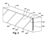
金属材料の溶接中に生成したガスを除去すると、溶接部内部でポロシティが生じるおそれが減るので、溶接プロセスに有益である。かかるガスを除去する一つの経路は、シムを用いて形成されるベント経路を通すものである。シムは、溶接プロセスの一部として予め存在していてよい。シムは、溶接中に生成したガスを除去するためのベント経路を生じるように配置すればよい。図面を参照すると、図3は本発明の一実施形態を示すもので、溶接継手接合面106を含む金属材料部材102、第1の金属シム302とその隣りの第2の金属シム306とそれらの間の第1のベント経路304がある。溶接プロセス中に生成したガスは、溶融池の前方でベント経路304を通して金属材料部材102から除去することができる。
Removing the gas generated during the welding of the metal material is beneficial to the welding process because it reduces the risk of porosity inside the weld. One path for removing such gas is through a vent path formed using shims. The shim may be pre-existing as part of the welding process. The shim may be arranged to create a vent path for removing gas generated during welding. Referring to the drawings, FIG. 3 illustrates one embodiment of the present invention, in which a
一実施形態では、2つの金属材料部材102の溶接に用いられる溶接用シムシステムを提供する。本システムは、2つの金属材料部材102間の溶接継手接合面106の平面内に配置するための、傾斜縁部310を有する第1の金属シム302と、2つの金属材料部材102間の溶接継手接合面106の平面内に配置するための、第1の金属シム302の傾斜縁部310と相補的な傾斜縁部312を有する第2の金属シム306とを備える。sらに、本システムは、傾斜縁部310と相補的な傾斜縁部312の間に第1のベント経路304が存在するようにシムを位置決めするための、第1の金属シム302又は第2の金属シム306の少なくとも一方に設けられた要素314を有する。追加の一実施形態では、第1のシム302及び第2のシム306は各々金属材料を含む。シムの材料、シムの傾斜角度及びシムのギャップ間隔は、溶接パラメータ及び接合すべき金属材料に関連する。溶接パラメータとしては、例えば、電子ビームへの電力、電子ビームへの電流、ビームの移動速度、振動、周波数及び焦点を制御することが上げられる。別の実施形態では、各金属シムは略平行四辺形の形状を有する。別の実施形態では、傾斜縁部310及び相補的な傾斜縁部312はビーム溶接角度に対して約20〜60度である。
In one embodiment, a welding shim system for use in welding two
別の実施形態では、2つの金属材料部材102間の溶接継手接合面106の平面内に配置するための、隣接する第2のシム306(この場合には第2の金属シム)の第2の傾斜縁部315に対して第2の相補的な傾斜縁部316を有する第3の金属シム309又は任意の数の追加のシムを設けてもよい。第2の相補的な傾斜縁部316と第2の傾斜縁部315の間に第2のベント経路308が存在するようにシムを位置決めするための、第2のシム306又は第3のシム309の少なくとも一方に設けられた要素318を設けてもよい。
In another embodiment, the second of the adjacent second shim 306 (in this case, the second metal shim) for placement in the plane of the
第1のベント経路304及び第2のベント経路308は、溶接プロセス中に生成したガスが溶融池の前方で逃散できるようにする。一実施形態では、第1のシムと第2のシムは最大0.100インチの間隔で互いに隔てられる。金属材料部材102に沿って溶接が進行する際、溶接プロセス中に生成したガスは、溶融池の前方のベント経路304,308を通して導くことができる。溶接プロセス中にガスが逃散できるようにすると、ポロシティ202を含む溶接部(図2)の形成を低減又はなくすことができる。したがって、溶接プロセスに起因するガスがベント経路304,308を通して逃散できるようにすると、図4に示すように、ポロシティのない溶接部を得ることができる。ポロシティのない溶接部402は、2以上の金属材料間の好ましい溶接部である。
The
図5を参照すると、隣接シム302,306間にベント経路304を有するシム302,306を用いて2つの金属材料部材102をビーム溶接機504で溶接する別の実施形態が示してある。金属材料部材102に沿ってビーム溶接機504を進行させると、ポロシティのない溶接部502が生じる金属材料部材102に沿って。ビーム溶接機504を進行させる際に、溶接先端508は、第1のベント経路304の端303に達する前に第2のシム306及び第2のベント経路308と接触する。すなわち、第1のベント経路304の終端部は、ベント経路が常に利用できるように、第2のベント経路308に十分接近している。このプロセスは、あらゆる段階で、溶接プロセスで発生した溶接ガス506が溶融池510の前方で確実に逃散できるようにする。ビーム溶接機504からガス506を逃散させるためのベント経路304,308が常に存在すようにシム302,306を溶接継手接合面106に沿って整列させることによって、シム302,306は、ポロシティ202をもつ溶接部(図2)を形成するおそれを低減し、ポロシティのない溶接部402(図4)を生じる確率を高める。金属材料部材102とシム104の溶接部は、ビーム溶接504を用いて形成することができる。一実施形態では、ビーム溶接504は電子ビームである。別の実施形態では、ビーム溶接504はレーザビームである。
Referring to FIG. 5, another embodiment is shown in which two
本発明の様々な態様に関する以上の記載は例示のためのものである。以上の記載は、本発明を限定するものではなく、多くの変更形態及び変形形態が可能であることは自明である。当業者に自明な変更及び変形は、特許請求の範囲によって規定される本発明の技術的範囲に属する。 The above description of various aspects of the invention is for illustrative purposes. The above description does not limit the present invention, and it is obvious that many modifications and variations are possible. Modifications and variations obvious to those skilled in the art belong to the technical scope of the present invention defined by the claims.
102 金属材料部材
106 継手接合面
202 ポロシティ
302 第1のシム
303 端部
302,306 シム
304 第1のベント経路
304,308 ベント経路
306 第2のシム
308 第2のベント経路
309 第3のシム
310 傾斜縁部
312 相補的な傾斜縁部
314,318 要素
315 第2の傾斜縁部
316 第2の相補的な傾斜縁部
402,502 ポロシティのない溶接部
504 ビーム溶接機
506 溶接ガス
508 溶接先端
510 溶融池
DESCRIPTION OF
Claims (18)
2つの金属材料部材間の溶接継手接合面に沿って第1のシムを配置し、
2つの金属材料部材間の溶接継手接合面に沿って第1のシムから所定の距離に第2のシムを配置して、第1のシムと第2のシムの間に第1のベント経路を形成し、
金属材料部材をシムを用いてビーム溶接して、ポロシティのない溶接部を形成する
ことを含む方法。 A method of beam welding two metal material members,
Placing a first shim along the weld joint interface between the two metal material members;
A second shim is disposed at a predetermined distance from the first shim along the weld joint interface between the two metal material members, and the first vent path is provided between the first shim and the second shim. Forming,
Beam welding a metallic material member with a shim to form a porosity free weld.
2つの金属材料部材間の溶接継手接合面の平面内に配置するための、傾斜縁部を有する第1のシムと、
2つの金属材料部材間の溶接継手接合面の平面内に配置するための、第1のシムの傾斜縁部と相補的な傾斜縁部を有する第2のシムと、
傾斜縁部と相補的な傾斜縁部の間に第1のベント経路が存在するようにシムを位置決めするための、第1のシム及び第2のシムの少なくとも一方に設けられた要素と
を備えるシステム。 A welding shim system used for welding two metal material members,
A first shim having an inclined edge for placement in the plane of a weld joint interface between two metallic material members;
A second shim having an inclined edge complementary to the inclined edge of the first shim for placement in the plane of the weld joint interface between the two metallic material members;
An element provided on at least one of the first shim and the second shim for positioning the shim such that there is a first vent path between the inclined edge and the complementary inclined edge. system.
Applications Claiming Priority (2)
| Application Number | Priority Date | Filing Date | Title |
|---|---|---|---|
| US12/435,430 | 2009-05-05 | ||
| US12/435,430 US20100282719A1 (en) | 2009-05-05 | 2009-05-05 | Vented shim beam welding process |
Publications (2)
| Publication Number | Publication Date |
|---|---|
| JP2010260102A true JP2010260102A (en) | 2010-11-18 |
| JP5615028B2 JP5615028B2 (en) | 2014-10-29 |
Family
ID=42313515
Family Applications (1)
| Application Number | Title | Priority Date | Filing Date |
|---|---|---|---|
| JP2010102872A Expired - Fee Related JP5615028B2 (en) | 2009-05-05 | 2010-04-28 | Vented shim beam welding process |
Country Status (3)
| Country | Link |
|---|---|
| US (1) | US20100282719A1 (en) |
| EP (1) | EP2248624B1 (en) |
| JP (1) | JP5615028B2 (en) |
Families Citing this family (6)
| Publication number | Priority date | Publication date | Assignee | Title |
|---|---|---|---|---|
| US20100282719A1 (en) * | 2009-05-05 | 2010-11-11 | General Electric Company | Vented shim beam welding process |
| US20110095000A1 (en) * | 2009-10-27 | 2011-04-28 | General Electric Co. | Workpiece and welding process for preventing porosity in a formed weld |
| RU2642218C1 (en) * | 2017-02-02 | 2018-01-24 | Публичное акционерное общество "Челябинский трубопрокатный завод" (ПАО "ЧТПЗ") | Method of laser welding of longitudinal pipe seam (versions) |
| CN108890131B (en) * | 2018-09-25 | 2020-04-03 | 长沙理工大学 | Method for laser deep fusion welding of plate based on prefabricated flow channel |
| US11801574B2 (en) * | 2020-03-06 | 2023-10-31 | GM Global Technology Operations LLC | Welding systems and methods with knurled weld interfaces for metallic workpieces |
| CN112247377A (en) * | 2020-09-03 | 2021-01-22 | 株洲国创轨道科技有限公司 | Laser deep melting welding method and device |
Citations (9)
| Publication number | Priority date | Publication date | Assignee | Title |
|---|---|---|---|---|
| JPS6487090A (en) * | 1987-09-30 | 1989-03-31 | Toyo Seikan Kaisha Ltd | Butt welding method by laser beam |
| JPH08215871A (en) * | 1995-02-15 | 1996-08-27 | Kawasaki Steel Corp | Laser welding method for high-carbon steel strip |
| JPH10277638A (en) * | 1997-04-02 | 1998-10-20 | Nippon Steel Corp | Welding method for steel tube, and steel tube to be welded |
| JPH1119791A (en) * | 1997-07-01 | 1999-01-26 | Ishikawajima Harima Heavy Ind Co Ltd | Method for joining thick metal plate |
| US6060682A (en) * | 1997-11-13 | 2000-05-09 | Westbroek; Wido | Overlapping joint for laser welding of tailored blanks |
| JP2001246486A (en) * | 2000-03-02 | 2001-09-11 | Kobe Steel Ltd | Welding method for joint |
| JP2007007730A (en) * | 2005-06-30 | 2007-01-18 | General Electric Co <Ge> | Shimmed laser beam welding process for joining superalloys for gas turbine application |
| EP2127795A2 (en) * | 2008-05-28 | 2009-12-02 | LFK-Lenkflugkörpersysteme GmbH | Design of a T-shape weld connection |
| EP2248624B1 (en) * | 2009-05-05 | 2014-01-01 | General Electric Company | Method of beam welding two members using vented shims ; corresponding beam welder and vented shims |
Family Cites Families (6)
| Publication number | Priority date | Publication date | Assignee | Title |
|---|---|---|---|---|
| US3056195A (en) * | 1959-06-04 | 1962-10-02 | Western Gold And Platinum Comp | Method of brazing |
| US3032870A (en) * | 1959-06-18 | 1962-05-08 | North American Aviation Inc | Brazed joint and fabrication method |
| US3427707A (en) * | 1965-12-16 | 1969-02-18 | Connecticut Research & Mfg Cor | Method of joining a pipe and fitting |
| US4801066A (en) * | 1988-04-01 | 1989-01-31 | Gte Products Corporation | Slotted brazing alloy strip |
| US6489583B1 (en) * | 2000-08-11 | 2002-12-03 | General Electric Company | Shimmed electron beam welding process |
| US20080164301A1 (en) * | 2007-01-10 | 2008-07-10 | General Electric Company | High temperature laser welding |
-
2009
- 2009-05-05 US US12/435,430 patent/US20100282719A1/en not_active Abandoned
-
2010
- 2010-04-28 JP JP2010102872A patent/JP5615028B2/en not_active Expired - Fee Related
- 2010-04-30 EP EP10161570.6A patent/EP2248624B1/en not_active Not-in-force
Patent Citations (9)
| Publication number | Priority date | Publication date | Assignee | Title |
|---|---|---|---|---|
| JPS6487090A (en) * | 1987-09-30 | 1989-03-31 | Toyo Seikan Kaisha Ltd | Butt welding method by laser beam |
| JPH08215871A (en) * | 1995-02-15 | 1996-08-27 | Kawasaki Steel Corp | Laser welding method for high-carbon steel strip |
| JPH10277638A (en) * | 1997-04-02 | 1998-10-20 | Nippon Steel Corp | Welding method for steel tube, and steel tube to be welded |
| JPH1119791A (en) * | 1997-07-01 | 1999-01-26 | Ishikawajima Harima Heavy Ind Co Ltd | Method for joining thick metal plate |
| US6060682A (en) * | 1997-11-13 | 2000-05-09 | Westbroek; Wido | Overlapping joint for laser welding of tailored blanks |
| JP2001246486A (en) * | 2000-03-02 | 2001-09-11 | Kobe Steel Ltd | Welding method for joint |
| JP2007007730A (en) * | 2005-06-30 | 2007-01-18 | General Electric Co <Ge> | Shimmed laser beam welding process for joining superalloys for gas turbine application |
| EP2127795A2 (en) * | 2008-05-28 | 2009-12-02 | LFK-Lenkflugkörpersysteme GmbH | Design of a T-shape weld connection |
| EP2248624B1 (en) * | 2009-05-05 | 2014-01-01 | General Electric Company | Method of beam welding two members using vented shims ; corresponding beam welder and vented shims |
Also Published As
| Publication number | Publication date |
|---|---|
| US20100282719A1 (en) | 2010-11-11 |
| EP2248624A1 (en) | 2010-11-10 |
| EP2248624B1 (en) | 2014-01-01 |
| JP5615028B2 (en) | 2014-10-29 |
Similar Documents
| Publication | Publication Date | Title |
|---|---|---|
| JP5615028B2 (en) | Vented shim beam welding process | |
| JP5496152B2 (en) | Combined welding method of laser welding and arc welding of T type joint | |
| JP5873658B2 (en) | Hybrid laser arc welding process and apparatus | |
| JP5941252B2 (en) | Hybrid laser arc welding process and apparatus | |
| JP2009090349A (en) | Method and apparatus for welding impeller | |
| WO2015189883A1 (en) | Laser welding method | |
| JP2009262186A (en) | Method of laser welding metal plated plate | |
| JP2008272826A (en) | Stiffened plate and process for producing the same | |
| JPWO2015159514A1 (en) | Laser welding method | |
| JP6607050B2 (en) | Laser-arc hybrid welding method | |
| JP2007237216A (en) | Laser beam welding method and laser beam welding equipment | |
| JP7189516B2 (en) | Weld defect repair method | |
| JP2008221294A (en) | Method and apparatus for repairing weld zone | |
| JP6620683B2 (en) | Welding method | |
| JP2012223799A (en) | Method of manufacturing welded joint | |
| JP2005279744A (en) | Butt welding method of different kind of material using high energy beam | |
| JP6989549B2 (en) | Manufacturing method of the joint | |
| JP2005199287A (en) | Weld bead structure and welding method | |
| JP2012228716A (en) | Laser welding apparatus and laser welding method | |
| US20160114433A1 (en) | Method of welding in deep joints | |
| JP6684548B2 (en) | Chip joining method | |
| JP2021109184A (en) | Laser welding method | |
| JP2016091932A (en) | Current cutoff device, manufacturing method of current cutoff device, and secondary battery | |
| JP2016047552A5 (en) | Laser welding method | |
| JP5489005B2 (en) | Welding method |
Legal Events
| Date | Code | Title | Description |
|---|---|---|---|
| A621 | Written request for application examination |
Free format text: JAPANESE INTERMEDIATE CODE: A621 Effective date: 20130424 |
|
| A131 | Notification of reasons for refusal |
Free format text: JAPANESE INTERMEDIATE CODE: A131 Effective date: 20140304 |
|
| A521 | Request for written amendment filed |
Free format text: JAPANESE INTERMEDIATE CODE: A523 Effective date: 20140530 |
|
| TRDD | Decision of grant or rejection written | ||
| A01 | Written decision to grant a patent or to grant a registration (utility model) |
Free format text: JAPANESE INTERMEDIATE CODE: A01 Effective date: 20140812 |
|
| A61 | First payment of annual fees (during grant procedure) |
Free format text: JAPANESE INTERMEDIATE CODE: A61 Effective date: 20140909 |
|
| R150 | Certificate of patent or registration of utility model |
Ref document number: 5615028 Country of ref document: JP Free format text: JAPANESE INTERMEDIATE CODE: R150 |
|
| R250 | Receipt of annual fees |
Free format text: JAPANESE INTERMEDIATE CODE: R250 |
|
| R250 | Receipt of annual fees |
Free format text: JAPANESE INTERMEDIATE CODE: R250 |
|
| LAPS | Cancellation because of no payment of annual fees |