JP2010258752A - Image forming apparatus - Google Patents
Image forming apparatus Download PDFInfo
- Publication number
- JP2010258752A JP2010258752A JP2009106063A JP2009106063A JP2010258752A JP 2010258752 A JP2010258752 A JP 2010258752A JP 2009106063 A JP2009106063 A JP 2009106063A JP 2009106063 A JP2009106063 A JP 2009106063A JP 2010258752 A JP2010258752 A JP 2010258752A
- Authority
- JP
- Japan
- Prior art keywords
- image
- mark
- area
- data
- image data
- Prior art date
- Legal status (The legal status is an assumption and is not a legal conclusion. Google has not performed a legal analysis and makes no representation as to the accuracy of the status listed.)
- Granted
Links
Images


Classifications
-
- H—ELECTRICITY
- H04—ELECTRIC COMMUNICATION TECHNIQUE
- H04N—PICTORIAL COMMUNICATION, e.g. TELEVISION
- H04N1/00—Scanning, transmission or reproduction of documents or the like, e.g. facsimile transmission; Details thereof
- H04N1/0035—User-machine interface; Control console
- H04N1/00352—Input means
- H04N1/00355—Mark-sheet input
- H04N1/00368—Location of the scanned marks
- H04N1/00374—Location of the scanned marks on the same page as at least a part of the image
-
- H—ELECTRICITY
- H04—ELECTRIC COMMUNICATION TECHNIQUE
- H04N—PICTORIAL COMMUNICATION, e.g. TELEVISION
- H04N1/00—Scanning, transmission or reproduction of documents or the like, e.g. facsimile transmission; Details thereof
- H04N1/0035—User-machine interface; Control console
- H04N1/00352—Input means
- H04N1/00355—Mark-sheet input
- H04N1/00358—Type of the scanned marks
-
- H—ELECTRICITY
- H04—ELECTRIC COMMUNICATION TECHNIQUE
- H04N—PICTORIAL COMMUNICATION, e.g. TELEVISION
- H04N1/00—Scanning, transmission or reproduction of documents or the like, e.g. facsimile transmission; Details thereof
- H04N1/0035—User-machine interface; Control console
- H04N1/00352—Input means
- H04N1/00355—Mark-sheet input
- H04N1/00376—Means for identifying a mark sheet or area
-
- H—ELECTRICITY
- H04—ELECTRIC COMMUNICATION TECHNIQUE
- H04N—PICTORIAL COMMUNICATION, e.g. TELEVISION
- H04N2201/00—Indexing scheme relating to scanning, transmission or reproduction of documents or the like, and to details thereof
- H04N2201/0077—Types of the still picture apparatus
- H04N2201/0094—Multifunctional device, i.e. a device capable of all of reading, reproducing, copying, facsimile transception, file transception
Landscapes
- Engineering & Computer Science (AREA)
- Computer Vision & Pattern Recognition (AREA)
- Multimedia (AREA)
- Signal Processing (AREA)
- Editing Of Facsimile Originals (AREA)
- Control Or Security For Electrophotography (AREA)
Abstract
Description
本発明は、画像形成装置に関し、特には、手書き画像を抽出するための技術に関する。 The present invention relates to an image forming apparatus, and more particularly to a technique for extracting a handwritten image.
従来、原稿画像の画像データから、原稿画像にペン等によって手書きされた画像(以下「手書き画像」と記す。)に基づく画像データを抽出し、抽出した画像データに対して、消去処理及び強調処理等の各種画像処理を施す技術が数多く提案されている。 Conventionally, image data based on an image handwritten on a document image with a pen or the like (hereinafter referred to as “handwritten image”) is extracted from the image data of the document image, and erase processing and enhancement processing are performed on the extracted image data. Many techniques for performing various image processing such as these have been proposed.
例えば、後掲の特許文献1には、入力された画像データにおける所定長以上の線分と、この線分の色スペクトラムとを検出し、画像データのうち、検出した線分と同一の色スペクトラムを持つ部分を原稿部分として判断し、異なる色スペクトラムを持つ部分を手書き部分として判断する技術について開示されている。
For example, in
また、後掲の特許文献2には、コピー画像を読取ることで、コピー画像中の、マーカーペン等によって手書きされた中間調の線分で囲まれた領域を認識するとともに、画像形成装置側に予め記憶される原稿の画像データのうち、認識した領域に対応する領域の内部又は外部の画像データに対し、トリミング又はマスキング等の処理を施す技術について開示されている。
Further, in
特許文献1に開示される技術では、例えば、白黒画像上に赤色インクのペンを用いて手書き画像が書込まれた場合等の、原稿画像の色スペクトルと手書き画像の色スペクトルが顕著に異なる場合には、正確に手書き部分の位置を判断することができる。一方、例えば、カラー画像上に手書き画像が書込まれた場合、及び、原稿画像上に複数のインクのペンを用いて手書き画像が書込まれた場合等の、原稿画像及び手書き画像に使用される色スペクトルが複雑である場合には、誤判断が生じるおそれがある。
In the technique disclosed in
特許文献2に開示される技術では、ユーザが所望する領域を抽出する場合、マーカーペン等によって所望の領域を囲む囲み線を書込まなければならない。そのため、手書き画像を消去したい場合等には、更に手書きの囲み線を追加する必要がある。また、手書きされた領域が原稿画像と複雑に入り混じっている場合等には、囲み線を形成する作業自体が困難であり、実用性に欠ける。
In the technique disclosed in
本発明の目的は、確実かつ容易に手書き画像を抽出できる画像形成装置を提供することである。本発明の他の目的は、手書き画像に基づく画像データに対して確実に所望の処理を実行可能な画像形成装置を提供することである。 An object of the present invention is to provide an image forming apparatus capable of extracting a handwritten image reliably and easily. Another object of the present invention is to provide an image forming apparatus capable of reliably executing desired processing on image data based on a handwritten image.
本発明の第1の局面に係る画像形成装置は、特定領域を含む原稿画像に基づく第1の画像データを作成する第1の画像データ作成手段と、第1の画像データから、特定領域の画像データを抽出する特定領域抽出手段と、第1の画像データのうち、抽出された特定領域の画像データと、マーク画像を出力するためのマーク画像データとを合成することで合成データを作成するマーク画像付与手段と、合成データに基づいて、マーク画像が形成された領域であるマーク領域を含む第1の画像を出力する第1の出力手段と、を含む。 An image forming apparatus according to a first aspect of the present invention includes a first image data creating unit that creates first image data based on a document image including a specific area, and an image of the specific area from the first image data. Specific area extracting means for extracting data, and a mark for generating composite data by combining image data of the extracted specific area of the first image data and mark image data for outputting a mark image Image adding means, and first output means for outputting a first image including a mark area, which is an area where the mark image is formed, based on the composite data.
このように、第1の画像における、原稿画像の特定領域に対応する領域にマーク領域を形成するので、マーク領域を抽出することで、特定領域に対応する領域に形成された手書き画像を確実かつ容易に抽出することができる。 As described above, the mark area is formed in the area corresponding to the specific area of the original image in the first image. Therefore, by extracting the mark area, the handwritten image formed in the area corresponding to the specific area It can be easily extracted.
好ましくは、特定領域は、原稿画像において、画像が形成されていない領域である。 Preferably, the specific area is an area where no image is formed in the document image.
より好ましくは、特定領域は、原稿画像において、予め定める一定面積以上であって、かつ、予め定める一定範囲内の画像濃度値を有する画像が形成されている領域である。 More preferably, the specific area is an area where an image having an image density value that is equal to or larger than a predetermined fixed area and within a predetermined fixed range is formed in the document image.
さらに好ましくは、特定領域は、原稿画像において、予め定める一定の明度以上の画像が形成されている領域である。 More preferably, the specific area is an area in which an image having a predetermined lightness or higher is formed in the document image.
このように、特定領域として、手書き画像が形成され易いと予想される領域が設定されるので、手書き画像をより一層確実かつ容易に抽出することができる。 As described above, since the region where the handwritten image is expected to be easily formed is set as the specific region, the handwritten image can be extracted more reliably and easily.
さらに好ましくは、マーク画像の色相は、イエローである。このように、マーク画像の色相が視覚によって認識しにくいイエローであることによって、マーク画像の付与に伴う第1の画像の画質の低下を最小限に抑えることができる。 More preferably, the hue of the mark image is yellow. As described above, since the hue of the mark image is yellow that is difficult to recognize visually, the deterioration of the image quality of the first image accompanying the application of the mark image can be minimized.
さらに好ましくは、マーク画像は複数のドットから構成され、ドットは、1×1画素〜8×8画素の点である。このように、マーク画像が、視覚によって認識しにくい充分小さいドットから構成されることで、マーク画像の付与に伴う第1の画像の画質の低下を最小限に抑えることができ、第1の画像が見にくくなることをより一層確実に防ぐことができる。 More preferably, the mark image is composed of a plurality of dots, and the dots are points of 1 × 1 pixel to 8 × 8 pixels. In this way, the mark image is composed of sufficiently small dots that are difficult to recognize visually, so that the deterioration of the image quality of the first image accompanying the application of the mark image can be minimized. Can be more reliably prevented from becoming difficult to see.
さらに好ましくは、画像形成装置は、第1の画像に基づく第2の画像データを作成する第2の画像データ作成手段と、第2の画像データから、マーク領域の画像データを抽出するマーク領域抽出手段と、第2の画像データのうち、抽出されたマーク領域の画像データに対し、所定の画像処理を行なう特定領域用画像処理手段と、所定の画像処理後の第2の画像データに基づく第2の画像を出力する第2の出力手段とを含む。
このように、第1の画像に基づく第2の画像データからマーク領域の画像データを抽出し、抽出したマーク領域のデータに対して所定の画像処理を行なうので、マーク領域に形成された手書き画像に基づく画像データに対して確実に所望の画像処理を実行することができる。
More preferably, the image forming apparatus includes a second image data creation unit that creates second image data based on the first image, and a mark area extraction that extracts image data of the mark area from the second image data. Means, specific area image processing means for performing predetermined image processing on the image data of the extracted mark area in the second image data, and second image data based on the second image data after the predetermined image processing. Second output means for outputting two images.
In this way, the image data of the mark area is extracted from the second image data based on the first image, and the predetermined image processing is performed on the extracted data of the mark area, so that the handwritten image formed in the mark area The desired image processing can be reliably executed on the image data based on the above.
さらに好ましくは、マーク画像は、既知の所定の間隔、例えば約1mmの間隔を有して配置される複数のドットから構成され、マーク領域抽出手段は、複数のドットの少なくとも一部を検出することで、第2の画像データから、マーク領域の画像データを抽出する。
これにより、マーク画像を構成する複数のドットが、一般的に使用されるペン等の線画像の太さよりも広い間隔を有するように配置されるので、複数のドットのうちの一部は手書き画像部分から外れることができ、マーク画像全体が手書き画像によって覆われてしまうことを避けることができる。したがって、マーク画像上に手書き画像が形成された場合においても、マーク領域の画像データを確実に抽出することができるので、マーク領域に形成された手書き画像をさらに確実に抽出することができる。
More preferably, the mark image is composed of a plurality of dots arranged with a known predetermined interval, for example, an interval of about 1 mm, and the mark area extracting means detects at least a part of the plurality of dots. Thus, the image data of the mark area is extracted from the second image data.
As a result, the plurality of dots constituting the mark image are arranged so as to have a wider interval than the thickness of a line image such as a pen that is generally used, so that some of the plurality of dots are handwritten images. Therefore, it is possible to prevent the entire mark image from being covered with the handwritten image. Therefore, even when a handwritten image is formed on the mark image, the image data of the mark area can be reliably extracted, so that the handwritten image formed in the mark area can be more reliably extracted.
さらに好ましくは、特定領域用画像処理手段は、第2の画像データのうち、抽出されたマーク領域の画像データを消去する。これによって、第2の画像中の手書き画像を消去することができるので、元の原稿画像を消失した場合においても、元の原稿画像と同様の原稿画像を得ることができる。 More preferably, the specific area image processing means erases the image data of the extracted mark area from the second image data. As a result, the handwritten image in the second image can be erased, so that even when the original document image is lost, a document image similar to the original document image can be obtained.
さらに好ましくは、特定領域用画像処理手段は、第2の画像データのうち、抽出されたマーク領域の画像データに対し、パターン認識処理を行なう。これによって、例えば、回答欄が特定領域として予め定められるアンケート用紙等において、原稿画像の向きに影響されることなく、マーク領域に書込まれた手書き画像を認識することができるので、回答欄の位置を自由に設定することができる。また、マーク領域の位置から、原稿画像の向きを判定することができる。さらに、第2の画像データ全体に対してパターン認識を行なう必要がなく、また、原稿画像の向きを判定した後にパターン認識を行なうことができるので、効率良くパターン認識を行なうことができる。 More preferably, the specific area image processing means performs a pattern recognition process on the image data of the extracted mark area in the second image data. Thus, for example, in a questionnaire sheet or the like in which the answer field is predetermined as the specific area, the handwritten image written in the mark area can be recognized without being affected by the orientation of the original image. The position can be set freely. Further, the orientation of the document image can be determined from the position of the mark area. Furthermore, it is not necessary to perform pattern recognition on the entire second image data, and pattern recognition can be performed after determining the orientation of the document image, so that pattern recognition can be performed efficiently.
本発明の第2の局面に係る画像形成装置は、マーク画像が形成された領域であるマーク領域を含む第1の画像に基づく第1の画像データを作成する第1の画像データ作成手段と、第1の画像データから、マーク領域の画像データを抽出するマーク領域抽出手段と、第1の画像データのうち、抽出されたマーク領域の画像データに対し、所定の画像処理を行なう特定領域用画像処理手段と、所定の画像処理後の第1の画像データに基づく第2の画像を出力する出力手段とを含む。
このように、第1の画像に基づく第1の画像データからマーク領域の画像データを抽出し、抽出したマーク領域のデータに対して所定の画像処理を行なうので、マーク領域に形成された手書き画像に基づく画像データに対して確実に所望の画像処理を実行することができる。
An image forming apparatus according to a second aspect of the present invention includes: a first image data creating unit that creates first image data based on a first image including a mark area that is an area where a mark image is formed; Mark area extracting means for extracting image data of the mark area from the first image data, and a specific area image for performing predetermined image processing on the image data of the extracted mark area of the first image data Processing means and output means for outputting a second image based on the first image data after predetermined image processing.
In this way, the image data of the mark area is extracted from the first image data based on the first image, and the predetermined image processing is performed on the extracted data of the mark area, so that the handwritten image formed in the mark area The desired image processing can be reliably executed on the image data based on the above.
本発明によれば、第1の画像における、原稿画像の特定領域に対応する領域にマーク領域を形成するので、マーク領域を抽出することで、特定領域に対応する領域に形成された手書き画像を確実かつ容易に抽出することができる。また、第1の画像に基づく第1又は第2の画像データからマーク領域の画像データを抽出し、抽出したマーク領域のデータに対して所定の画像処理を行なうので、マーク領域に形成された手書き画像に基づく画像データに対して確実に所望の画像処理を実行することができる。 According to the present invention, the mark area is formed in the area corresponding to the specific area of the document image in the first image. Therefore, by extracting the mark area, the handwritten image formed in the area corresponding to the specific area is obtained. Extraction can be made reliably and easily. Further, the image data of the mark area is extracted from the first or second image data based on the first image, and predetermined image processing is performed on the extracted data of the mark area, so that the handwriting formed in the mark area Desired image processing can be reliably executed on image data based on an image.
以下の説明及び図面においては、同一の部品には同一の参照符号及び名称を付してある。それらの機能も同様である。したがって、それらについての詳細な説明は繰返さない。 In the following description and drawings, the same reference numerals and names are assigned to the same components. Their functions are also the same. Therefore, detailed description thereof will not be repeated.
〈ハードウェア構成〉
[画像形成装置1]
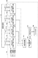
図1は、本発明の一実施の形態に係る画像形成装置1の構成を示すブロック図である。図1を参照して、画像形成装置1は、デジタル複合機である。画像形成装置1は、LAN(Local Area Network)回線等からなるネットワーク3を介して情報処理装置2と互いに接続される。画像形成装置1及び情報処理装置2は、画像データを含む各種データを相互に送受できる。
<Hardware configuration>
[Image forming apparatus 1]
FIG. 1 is a block diagram showing a configuration of an
情報処理装置2は、画像形成装置1を利用するために一般のユーザによって操作される、例えば、PC(Personal Computer)等の端末装置である。情報処理装置2には、図形描画ツール及びワードプロセッサ等のアプリケーションプログラム、並びに、画像データの印刷ジョブを実現するためのプリンタドライバがインストールされている。情報処理装置2は、上記アプリケーションプログラムを使用するユーザの指示に応じて、文字及び図形等を含む画像を出力するための画像データを作成し、作成した画像データをプリンタドライバによってプリンタ記述言語に変換して、画像形成装置1に対して送信できる。なお、図1には情報処理装置2を1つのみ図示するが、実際には多数存在する。
The
画像形成装置1は、制御部10、スキャナ部12、画像処理部14、マーク領域抽出部16、特定領域用画像処理部18、特定領域抽出部20、マーク画像付与部22、プリンタ部24、操作パネル26、NIC(Network Interface Card)28、及び、電源制御部30を含む。
The
制御部10は、実質的にコンピュータであって、CPU102、ROM104、RAM106及びHDD108を含む。CPU102には、BUSライン109が接続されており、このBUSライン109には、ROM104、RAM106及びHDD108が電気的に接続される。CPU102は、操作パネル26等からの指示に応じて各種コンピュータプログラムを実行することによって、画像形成装置1の各部の動作及び情報処理装置2との通信等の所望の処理を実行する。上記の各種コンピュータプログラムは、予めROM104又はHDD108に記憶されており、所望の処理の実行時において、当該ROM104又はHDD108から読出されてRAM106に転送される。CPU102は、CPU102内の図示しないプログラムカウンタと呼ばれるレジスタに格納された値によって指定される、RAM106内のアドレスからプログラムの命令を読出し、解釈する。CPU102はまた、読出された命令によって指定されるアドレスから演算に必要なデータを読出し、そのデータに対し命令に対応する演算を実行する。実行の結果も、RAM106、HDD108及びCPU102内のレジスタ等の、命令によって指定されるアドレスに格納される。
The
HDD108には、画像形成装置1の一般的な動作を実現するためのコンピュータプログラムとともに、後述する、マーク付与処理及び特定領域用画像処理を実現するためのコンピュータプログラムが記憶される。このコンピュータプログラムは、ネットワーク3及びNIC28を介して情報処理装置2から提供される。なお、このコンピュータプログラムは、そのコンピュータプログラムが記録された、例えばDVD等の記録媒体によって提供されてもよい。すなわち、コンピュータプログラムの記録媒体としてのDVDが、画像形成装置1内に内蔵されるDVDドライブ(図示せず。)に装着され、そのDVDからコンピュータプログラムが読出されてHDD108にインストールされてもよい。HDD108は、他に、画像データ等を含む各種データを記憶する。
The
BUSライン109には、さらに、スキャナ部12、画像処理部14、マーク領域抽出部16、特定領域用画像処理部18、特定領域抽出部20、マーク画像付与部22、プリンタ部24、操作パネル26、NIC28、及び、電源制御部30が電気的に接続される。
The
図2は、スキャナ部12の構成及び動作を説明するためのブロック図である。図2を参照して、スキャナ部12は、露光用ランプ122及びレンズ等の光学系124を含むスキャナ光学ユニット120と、CCD(Charge−Coupled Device)制御部126及びCCDラインセンサ128を含むCCD部125と、スキャナ画像処理部130とを含む。スキャナ光学ユニット120は、原稿100のコピー時又はスキャン時に、ユーザによって手動で、又は、自動原稿搬送装置(図示せず。)によって、原稿載置台(図示せず。)上に載置される原稿100の原稿画像表面に対し露光用ランプ122から光L1を照射することによって得られる反射光像L2を、光学系124を通してCCDラインセンサ128上に結像させる。CCDラインセンサ128は、CCD制御部126からの制御信号S1によって駆動され、結像された反射光像L2を順次光電変換して画像データD1としてスキャナ画像処理部130に対して出力する。スキャナ画像処理部130は、CCDラインセンサ128から入力される画像データD1に対して、例えば、シェーディング補正等を含む、スキャナ特性に応じた各種補正処理を施して、RGB(R:赤、G:緑、B:青)形式の画像データ(以下「RGBデータ」と記す。)D2を作成し、RGBデータD2を転送するタイミングを示すタイミング信号S2と同期して、作成したRGBデータD2を画像処理部14に対して順次出力する。なお、ユーザによって、特定領域用画像処理を実行する旨の指示がなされた場合には、RGBデータD2及びタイミング信号S2は、画像処理部14だけでなくマーク領域抽出部16に対しても順次出力される。
FIG. 2 is a block diagram for explaining the configuration and operation of the
図3は、マーク付与処理時における一連のデータの流れを示すブロック図である。画像処理部14は、MPU(Micro Processing Unit)及びRAM(以上いずれも図示せず。)を含む。図3を参照して、画像処理部14のMPUは、スキャナ画像処理部130からタイミング信号S2と同期して順次入力されるRGBデータD2、又は、情報処理装置2から送信される画像データに対して、RAM上にてマスキング処理等の色補正処理を含む各種画像処理を施して、YMCK(Y:イエロー、M:マゼンタ、C:シアン、K:ブラック)形式の画像データ(以下「YMCKデータ」と記す。)D3を作成する。そして、YMCKデータD3を転送するタイミングを示すタイミング信号S3と同期して、作成したYMCKデータD3をプリンタ部24に対して順次出力する。なお、ユーザによって、マーク付与処理を実行する旨の指示がなされた場合には、YMCKデータD3及びタイミング信号S3は、特定領域抽出部20及びマーク画像付与部22に対して順次出力される。
FIG. 3 is a block diagram showing a flow of a series of data during the mark providing process. The
特定領域抽出部20は、主・副走査カウンタ202と、領域検知部204と、マップメモリ206とを含む。主・副走査カウンタ202は、マーク付与処理時において画像処理部14から入力されるタイミング信号S3に応答して、YMCKデータD3の主走査方向及び副走査方向のアドレスを示すアドレス信号S4を生成し、生成したアドレス信号S4を領域検知部204及びマップメモリ206に対して順次出力する。このアドレス信号S4は、マップメモリ206に対し情報を書込むタイミングを示すタイミング信号としての機能も有する。
The specific
図4は、マップメモリ206の構造を説明するための図である。図4を参照して、マップメモリ206は、後述するマーク画像領域1つ分の情報に対し1つのメモリセル207が対応するように構成されたメモリである。このメモリセル207は1ビットの情報を記憶することができる。マップメモリ206において、メモリセル207が「0」を記憶する場合には、対応する領域がマーク画像を形成しない領域であることを示し、「1」を記憶する場合には、対応する領域がマーク画像を形成する領域であることを示す。ここで、マーク画像を形成する領域とは、原稿100の原稿画像において画像が形成されていない領域(以下「特定領域」と記す。)に対応する領域のことを示し、マーク画像を形成しない領域とは、原稿100の原稿画像において画像が形成されている領域(以下「画像領域」と記す。)に対応する領域のことを示す。なお、これらのメモリセル207は、画像処理部14から印刷停止を示す最後の信号であるタイミング信号S3が入力された場合に、全てのメモリセル207が「1」を記憶するように初期化される。これによって、マーク付与処理の開始時には、全てのメモリセル207が「1」を記憶した状態となる。
FIG. 4 is a diagram for explaining the structure of the
領域検知部204は、以下のようにして領域検知処理を行なう。すなわち、領域検知部204は、まず、画像処理部14から順次入力されるYMCKデータD3が、画像領域のデータ(以下「画像領域データ」と記す。)であるか否かを、後述するマーク画像領域1つ分のYMCKデータD3毎に判定する。そして、画像領域データであると判定した場合には、主・副走査カウンタ202から入力されるアドレス信号S4に基づいて、マップメモリ206における、画像領域データに対応するメモリセル207に「0」を書込む。一方、画像領域データではない、すなわち特定領域の画像データであると判定した場合には、何も行なわない。YMCKデータD3が画像領域データであるか否かの判定方法は、当該分野において一般的に使用される方法であれば特に限定されないが、例えば、マーク画像領域1つ分のYMCKデータD3における画像データ値が全て「0」でない場合、すなわち1つでも「1」がある場合に画像領域データであると判定する方法等がある。
The
マーク画像付与部22は、遅延バッファ222と、主・副走査カウンタ224と、マーク画像生成部226と、マーク画像合成部228とを含む。
The mark
遅延バッファ222は、FIFO(First−In First−Out)構造のメモリである。遅延バッファ222は、領域検知部204がマーク画像領域1つ分に相当するライン数の領域検知処理を終了し、マップメモリ206に対して少なくとも最初の判定結果を書込むまで、画像処理部14から入力されるタイミング信号S3及びYMCKデータD3を保持する。そして、上記した保持の後、タイミング信号S3を主・副走査カウンタ224及びプリンタ部24のLSU(Laser Scanning Unit)246に対して出力するとともに、YMCKデータD3を、マーク画像合成部228に対して順次転送する。これにより、遅延バッファ222は、タイミング信号S3の出力及びYMCKデータD3の転送を遅延させることができるので、マーク画像領域1つ分のYMCKデータD3に対する領域検知処理が終了するまで、マーク画像合成部228による合成データD6の作成処理の開始を遅延させることができる。
The
主・副走査カウンタ224は、遅延バッファ222から入力されるタイミング信号S3に応答して、YMCKデータD3の主走査方向及び副走査方向のアドレスを示すアドレス信号S5を生成し、生成したアドレス信号S5をマーク画像合成部228に対して出力する。このアドレス信号S5は、マップメモリ206から情報D5を読出すタイミングを示すタイミング信号としての機能も有する。主・副走査カウンタ224は、さらに、アドレス信号S5の出力に同期して、マーク画像データD4を作成するタイミングを示すタイミング信号S6をマーク画像生成部226に対して出力する。
In response to the timing signal S3 input from the
マーク画像生成部226は、タイミング信号S6に応答して、マーク画像データD4を作成するとともに、作成したマーク画像データD4を、マーク画像合成部228に対して出力する。図5は、マーク画像データD4に基づくマーク画像500の一例を示す図である。図5を参照して、YMCKデータD3等の画像データに基づく画像は、主走査方向及び副走査方向にマトリクス状に配列される複数の画素502からなる。マーク画像500において2×2画素は、1つのドット504を形成する。以下、個々のドット504を区別する場合には、アルファベットを参照符号の末尾に付し、総称する場合は参照符号のみで表す。マーク画像500は、主走査方向に平行な2辺及び副走査方向に平行な2辺によって形成される正方形領域の頂点にくるように配置される4つのドット504a〜504dからなる。これら4つのドット504a〜504d間の距離は、それぞれ1mmである。以下、この正方形領域をマーク画像領域506と記す。
The mark
なお、ドット504は2×2画素の点に限定されないが、1×1画素〜8×8画素の点であることが好ましい。また、ドット504間の距離は1mmに限定されない。 The dot 504 is not limited to a point of 2 × 2 pixels, but is preferably a point of 1 × 1 pixel to 8 × 8 pixels. Further, the distance between the dots 504 is not limited to 1 mm.
マーク画像合成部228は、主・副走査カウンタ224から入力されるアドレス信号S5に応答してメモリセル207に記憶される情報D5を順次読出し、読出した情報D5に基づいて、遅延バッファ222から順次転送されるYMCKデータD3が画像領域データであるか否かをマーク画像領域1つ分のYMCKデータD3毎に判定する。そして、画像領域データではないと判定した場合、すなわち、対応するメモリセル207から「1」が読出された場合には、YMCKデータD3と、マーク画像生成部226から入力されるマーク画像データD4とを合成して合成データD6を作成する。合成データD6は、プリンタ部24に対して出力される。一方、画像領域データであると判定した場合、すなわち、対応するメモリセル207から「0」が読出された場合には、データの合成は行なわれず、YMCKデータD3がそのまま合成データD6として、プリンタ部24に対して出力される。
The mark
プリンタ部24は、画像メモリ242及び印刷部244を含む。画像メモリ242は、RAMを含む。画像メモリ242は、制御部10等からの指示に応じて、印刷部244に送信するための、画像処理部14から順次入力されるYMCKデータD3、又は、マーク画像付与部22から順次入力される合成データD6をページ単位で一時的に記憶し、記憶したYMCKデータD3又は合成データD6を印刷部244による画像形成に同期して、印刷部244に対して出力する。印刷部244は、LSU246を含む。印刷部244は、さらに、感光体ドラム、帯電器、現像装置、転写装置、クリーニング装置及び定着装置、並びに、画像形成装置1に着脱自在に装着されるトナーカートリッジ、手差し給紙トレイ、第1給紙トレイ及び第2給紙トレイ(以上いずれも図示せず。)を含む。手差し給紙トレイ、第1給紙トレイ及び第2給紙トレイは、この順で上下に並ぶように設置され、記録用紙を保持し、用紙搬送部(図示せず。)に記録用紙を送給する。手差し給紙トレイは、ユーザが手動により所望の記録用紙を設置するためのトレイであり、第1給紙トレイ及び第2給紙トレイは、異なる大きさの記録用紙を保持するためのトレイである。印刷部244は、制御部10等からの指示に応じて、上記給紙トレイのいずれかから用紙搬送部を介して搬送される記録用紙上に、画像メモリ242から送信されるYMCKデータD3に基づく画像、又は、合成データD6に基づく画像(以下「第1画像」と記す。)を印刷する。
The
図6は、第1画像600の一例を示す図である。図6(A)は第1画像600全体を示す図であり、図6(B)は点線で囲まれた領域608の拡大図であり、図6(C)は第1画像600に手書き画像609が形成された状態を示す図である。図6(A)及び図6(B)を参照して、第1画像600は、文字領域602と、図形領域604と、文字領域602及び図形領域604を除いたマーク領域606とを含む。文字領域602及び図形領域604は画像領域に対応する領域であり、マーク領域606は特定領域に対応する領域である。マーク領域606には、マーク画像データD4に基づく複数のマーク画像500が、主走査方向及び副走査方向に予め定める一定間隔を有して並んで配置されるように付与されている。マーク画像500の色相としては、特に限定されるものではないが、特には、イエローであることが好ましい。本実施の形態では、画像形成装置1はカラー印刷が可能であるので、マーク画像500はイエロートナーによって印刷されている。以下、第1画像600が印刷された記録用紙を「マーク付与原稿」と記す。
FIG. 6 is a diagram illustrating an example of the
図6(C)を参照して、ユーザは、目印等のために、第1画像600のマーク領域606に手書き画像609を形成する。手書き画像609は、例えば、黒色インクのペンを用いて書込まれた線画像である。本実施の形態において、マーク画像500を構成する4つのドット504は、予め定める一定間隔(1mm)を有するように配置されている。すなわち、4つのドット504が、一般的に使用されるペンの線画像の太さよりも広い間隔を有するように配置されている。そのため、手書き画像609はマーク画像500の一部、すなわち2つのドット504上に形成されているが、マーク画像500全体が手書き画像609によって覆われてしまうことはない。
Referring to FIG. 6C, the user forms a
操作パネル26は、液晶ディスプレイからなる表示出力部と、操作キー及びタッチパネル等からなる操作インターフェイス部とを含む。表示出力部は、画像形成装置1の状態及び各種処理の状態に関する情報等の各種情報をユーザに提供する。操作インターフェイス部は、ユーザが画像形成装置1を操作するためのインターフェイスを提供する。操作パネル26は、また、液晶ディスプレイとタッチパネルとを重ねて構成される、ユーザに対して対話的な操作インターフェイスを提供する。この対話的な操作インターフェイスは、タッチパネルから画像形成装置1全体の動作に対するユーザの指示を受付けて、その指示の内容を液晶ディスプレイに表示するとともに、その指示に応じた制御信号を制御部10又は画像処理部14のMPU等に対して出力する。操作パネル26は、電源オン指示及び電源オフ指示を入力するための電源キー、印刷ジョブを開始させるための印刷スタートキー、マーク付与処理を開始させるためのマーク付与キー、並びに、特定領域用画像処理を開始させるための特定領域用画像処理キー等を含む。
The operation panel 26 includes a display output unit including a liquid crystal display and an operation interface unit including operation keys and a touch panel. The display output unit provides the user with various information such as information regarding the state of the
操作パネル26において、ユーザによってマーク付与キーが選択された後印刷スタートキーが押下されると、マーク付与処理が開始される。また、特定領域用画像処理キーが選択された後印刷スタートキーが押下されると、特定領域用画像処理が開始される。 When the print start key is pressed after the user has selected the mark assignment key on the operation panel 26, the mark assignment process is started. When the print start key is pressed after the specific area image processing key is selected, the specific area image processing is started.
図7は、特定領域用画像処理時における一連のデータの流れを示すブロック図である。図7を参照して、マーク領域抽出部16は、色フィルタ162と、主・副走査カウンタ164と、マーク検知部166と、マップメモリ168とを含む。
FIG. 7 is a block diagram showing a flow of a series of data during specific area image processing. Referring to FIG. 7, the mark
色フィルタ162は、スキャナ画像処理部130から順次入力されるRGBデータD2から、イエロー成分のデータ(以下「イエローデータ」と記す。)D7を抽出し、マーク検知部166に対して転送する。これによって、色フィルタ162において抽出されたイエローデータD7のみがマーク検知部166に対して出力される。
The
主・副走査カウンタ164は、特定領域用画像処理時においてスキャナ画像処理部130から入力されるタイミング信号S2に応答して、RGBデータD2の主走査方向及び副走査方向のアドレスを示すアドレス信号S7を生成し、生成したアドレス信号S7を、マーク検知部166及びマップメモリ168に対して出力する。このアドレス信号S7は、マップメモリ168に対し情報を書込むタイミングを示すタイミング信号としての機能も有する。
The main /
図8は、マップメモリ168の構造を説明するための図である。図8を参照して、マップメモリ168は、マーク画像領域1つ分の情報に対し1つのメモリセル169が対応するように構成されたメモリである。このメモリセル169は1ビットの情報を記憶することができる。マップメモリ168において、メモリセル169が「0」を記憶する場合には、対応する領域はマーク画像500が形成されていない領域に対応することを示し、「1」を記憶する場合には、対応する領域はマーク画像500が形成されたマーク領域606に対応する領域であることを示す。なお、これらのメモリセル169は、スキャナ画像処理部130から印刷停止を示す最後の信号であるタイミング信号S2が入力された場合に、全てのメモリセル169が「0」を記憶するように初期化される。これによって、特定領域用画像処理の開始時には、全てのメモリセルが「0」を記憶した状態となる。
FIG. 8 is a diagram for explaining the structure of the
マーク検知部166は、主・副走査カウンタ164から入力されるアドレス信号S7と、色フィルタ162から入力されるイエローデータD7とに基づいて、以下のようにしてマーク画像検知処理を行なう。すなわち、マーク検知部166は、まず、イエローデータD7内における、2×2画素からなる点の大きさのベタ画像となるデータであって、その周辺にベタ画像となるデータが存在しないデータを、1つのドット504に対応するドットデータとして検出する。次いで、マーク検知部166は、イエローデータD7に基づいて、検出したドットデータに基づくドット504から主走査方向及び副走査方向に予め定める一定間隔離れた位置に、他の3つのドット504が存在するか否かを判定する。そして、他の3つのドット504が存在すると判定した場合には、4つのドット504によって囲まれる領域をマーク画像領域506であると判断し、アドレス信号S7に基づいて、マーク画像領域506に対応するメモリセルに「1」を書込む。それ以外の場合には何も行なわない。マーク検知部166は、1ページ分のRGBデータD2に対するマーク画像検知処理を終了すると、マーク画像検知処理が終了したことを示す終了信号(図示せず。)を特定領域用画像処理部18に対して出力する。
Based on the address signal S7 input from the main /
特定領域用画像処理部18は、実際には制御部10により実行されるプログラムによって実現される。特定領域用画像処理部18は、マーク検知部166から入力される終了信号に応答して、マップメモリ168に記憶される情報D8を読出す。そして読出した情報D8に基づいて、画像処理部14にて画像処理中のRGBデータD2に対し、マーク画像500が形成されたマーク領域606の画像データを消去する画像消去処理を行なう。
The specific area
このとき、特定領域用画像処理部18は、メモリセル169にて「1」が記憶された領域をマーク領域606と判断するが、以下のような処理も併せて行なう。例えば、手書き画像609がマーク画像500の一部である2つのドット504上に形成されているために(図6(C)参照)、色フィルタ162によって上記2つのドット504に対応するイエローデータD7が抽出されない場合がある。この場合、マーク検知部166によるマーク画像検知処理が正確に行なわれないため、対応するメモリセル169に「0」が誤って記憶される。特定領域用画像処理部18は、誤った記憶処理に伴う誤判断を防ぐために、「0」を記憶するメモリセル169が孤立している場合(図8のメモリセル169a参照)、すなわち、「1」を記憶するメモリセル169によって「0」を記憶するメモリセル169が囲まれている場合には、孤立したメモリセル169に対応する領域をマーク領域606であると判断する。
At this time, the specific area
NIC28は、ネットワーク3とのインターフェイスをとる。画像形成装置1は、このNIC28を介して、ネットワーク3上の情報処理装置2とのデータ通信が可能である。
The
電源制御部30は、外部電源302と電気的に接続される。電源制御部30は、画像形成装置1の各部の動作に必要な電力を外部電源302から取得し、取得した電力を画像形成装置1の各部に供給する。
The power
画像形成装置1は、上述した各部を動作させることによって、操作パネル26からのユーザの入力操作による指示又は情報処理装置2等からの指示に応じて、原稿画像を読取り記録用紙に印刷するコピーモード、情報処理装置2等から送信される画像データを受信して記録用紙に印刷するプリンタモード、及び、原稿画像を読取り情報処理装置2等に送信するスキャナモード等の各種のモードのいずれかを実行する。
The
〈動作〉
図1〜図8を参照して、本実施の形態に係る画像形成装置1は、マーク付与処理時及び特定領域用画像処理時において以下のように動作する。なお、マーク付与処理時及び特定領域用画像処理時における動作を除く画像形成装置1の一般的な機能を実現するための動作は、従来の画像形成装置における動作と同様である。
<Operation>
Referring to FIGS. 1 to 8,
(マーク付与処理時における動作)
マーク付与処理開始時において、マップメモリ206の全てのメモリセル207(図4参照)は「1」を記憶した状態である。ユーザは、原稿100を原稿載置台(図示せず。)上に載置し、操作パネル26におけるマーク付与キーを選択した後、印刷スタートキーを押下する。印刷スタートキーが押下されると、スキャナ部12は、原稿載置台に載置される原稿100の原稿画像に基づくRGBデータD2を作成し、作成したRGBデータD2をタイミング信号S2と同期して画像処理部14に対して順次出力する。画像処理部14は、タイミング信号S2と同期して順次入力されるRGBデータD2に基づいて、YMCKデータD3を作成する。そして、作成したYMCKデータD3をタイミング信号S3と同期して、特定領域抽出部20及びマーク画像付与部22に対して順次出力する。
(Operation at the time of marking process)
At the start of the mark application process, all the memory cells 207 (see FIG. 4) of the
特定領域抽出部20において、主・副走査カウンタ202は、画像処理部14から入力されるタイミング信号S3に応答してアドレス信号S4を生成し、生成したアドレス信号S4を領域検知部204及びマップメモリ206に対して順次出力する。
In the specific
領域検知部204は、画像処理部14から順次入力されるYMCKデータD3が画像領域データであるか否かをマーク画像領域1つ分のYMCKデータD3毎に判定する。そして、画像領域データであると判定した場合には、主・副走査カウンタ202から入力されるアドレス信号S4に基づいて、マップメモリ206における、画像領域データに対応するメモリセル207に「0」を書込む。一方、画像領域データではない、すなわち、特定領域の画像データであると判定した場合には、何も行なわない。
The
マーク画像付与部22において、遅延バッファ222は、領域検知部204がマーク画像領域1つ分に相当するライン数の領域検知処理を終了し、マップメモリ206に対して少なくとも最初の判定結果を書込むまで、画像処理部14から入力されるタイミング信号S3及びYMCKデータD3を保持する。そして、上記した保持の後、タイミング信号S3を主・副走査カウンタ224及びプリンタ部24のLSU246に対して出力するとともに、YMCKデータD3を、マーク画像合成部228に対して順次転送する。
In the mark
主・副走査カウンタ224は、遅延バッファ222から入力されるタイミング信号S3に応答してアドレス信号S5を生成し、生成したアドレス信号S5をマーク画像合成部228に対して出力する。主・副走査カウンタ224は、さらに、アドレス信号S5の出力に同期して、タイミング信号S6をマーク画像生成部226に対して出力する。
The main /
マーク画像生成部226は、タイミング信号S6に応答してマーク画像データD4を作成するとともに、作成したマーク画像データD4をマーク画像合成部228に対して出力する。
The mark
マーク画像合成部228は、主・副走査カウンタ224から入力されるアドレス信号S5に応答してメモリセル207に記憶される情報D5を順次読出し、読出した情報D5に基づいて、遅延バッファ222から順次転送されるYMCKデータD3が画像領域データであるか否かをマーク画像領域1つ分のYMCKデータD3毎に判定する。そして、画像領域データではないと判定した場合、すなわち、対応するメモリセル207から「1」が読出された場合には、YMCKデータD3とマーク画像データD4とを合成して合成データD6を作成し、作成した合成データD6をプリンタ部24に対して出力する。一方、画像領域データであると判定した場合、すなわち、対応するメモリセル207から「0」が読出された場合には、データの合成は行なわず、YMCKデータD3をそのまま合成データD6として、プリンタ部24に対して出力する。最後のYMCKデータD3に基づく合成データD6が出力されると、画像処理部14から印刷停止を示す最後の信号であるタイミング信号S3が入力され、マップメモリ206における全てのメモリセル207が初期化される。
The mark
プリンタ部24は、マーク画像合成部228から順次入力される合成データD6に基づく第1画像600(図6参照)を記録用紙上に印刷する。このとき、第1画像600のマーク領域606におけるマーク画像500はイエロートナーによって印刷される。
The
(特定領域用画像処理時における動作)
特定領域用画像処理開始時において、マップメモリ168の全てのメモリセル169(図8参照)は「0」を記憶した状態である。ユーザは、第1画像600が印刷されたマーク付与原稿のマーク領域606に黒色インクのペンを用いて手書き画像609を形成する。そして、手書き画像609が形成されたマーク付与原稿を原稿載置台(図示せず。)上に載置し、操作パネル26の特定領域用画像処理キーを選択した後、印刷スタートキーを押下する。印刷スタートキーが押下されると、スキャナ部12は、原稿載置台に載置されるマーク付与原稿の原稿画像に基づくRGBデータD2を作成し、作成したRGBデータD2をタイミング信号S2と同期して画像処理部14及びマーク領域抽出部16に対して順次出力する。
(Operations during image processing for specific areas)
At the start of the specific area image processing, all the memory cells 169 (see FIG. 8) of the
マーク領域抽出部16において、色フィルタ162は、スキャナ画像処理部130から順次入力されるRGBデータD2から、イエローデータD7を抽出し、マーク検知部166に対して転送する。
In the mark
主・副走査カウンタ164は、スキャナ画像処理部130から入力されるタイミング信号S2に応答してアドレス信号S7を生成し、生成したアドレス信号S7を、マーク検知部166及びマップメモリ168に対して出力する。
The main /
マーク検知部166は、主・副走査カウンタ164から入力されるアドレス信号S7と、色フィルタ162から入力されるイエローデータD7とに基づいて、以下のようにしてマーク画像検知処理を行なう。すなわち、マーク検知部166は、まず、イエローデータD7内における、2×2画素からなる点の大きさのベタ画像となるデータであって、その周辺にベタ画像となるデータが存在しないデータを、1つのドット504aに対応するドットデータとして検出する(図5参照)。次いで、マーク検知部166は、イエローデータD7に基づいて、検出したドットデータに基づくドット504aから主走査方向及び副走査方向に予め定める一定間隔離れた位置に、他の3つのドット504b〜504dが存在するか否かを判定する。そして、他の3つのドット504b〜504dが存在すると判定した場合には、4つのドット504a〜504dによって囲まれる領域をマーク画像領域506であると判断し、アドレス信号S7に基づいて、マーク画像領域506に対応するメモリセルに「1」を書込み、それ以外の場合には何も行なわない。マーク検知部166は、1ページ分のRGBデータD2に対するマーク画像検知処理を終了すると、終了信号(図示せず。)を特定領域用画像処理部18に対して出力する。
Based on the address signal S7 input from the main /
画像処理部14は、タイミング信号S2と同期して順次入力されるRGBデータD2に基づいて、YMCKデータD3を作成する。このとき、特定領域用画像処理部18は、マーク検知部166から入力される終了信号に応答して、マップメモリ168に記憶される情報D8を読出す。そして読出した情報D8に基づいて、画像処理部14にて画像処理中のRGBデータD2に対し、マーク画像500が形成された領域であるマーク領域606の画像データを消去する画像消去処理を行なう。画像処理部14は、作成した画像消去処理後のYMCKデータD3をタイミング信号S3と同期して、プリンタ部24に対して順次出力する。最後のYMCKデータD3が出力されると、スキャナ画像処理部130から印刷停止を示す最後の信号であるタイミング信号S2が入力され、マップメモリ168における全てのメモリセル169が初期化される。
The
プリンタ部24は、画像処理部14から順次入力されるYMCKデータD3に基づく印刷画像(以下「第2画像」と記す。)を記録用紙上に印刷する。このとき、第2画像は、手書き画像609が消去された状態で印刷される。
The
[変形例]
画像形成装置1の変形例は、特定領域抽出部20に代えて特定領域抽出部70が設けられる点を除いて、上記実施の形態に係る画像形成装置1と同一の構成である。本変形例において、画像形成装置1と同一の機能を有する構成部には同一の参照符号及び名称を付し、それらについての詳細な説明は繰返さない。
[Modification]
The modified example of the
図9は、本変形例に係るマーク付与処理時における一連のデータの流れの一部を示すブロック図である。図9を参照して、特定領域抽出部70は、Y判定回路701と、M判定回路702と、C判定回路703と、K判定回路704と、判定合成部705と、RAMからなる判定保持用メモリ706と、領域判定部707と、マップメモリ708とを含む。
FIG. 9 is a block diagram showing a part of a series of data flow during the mark providing process according to this modification. Referring to FIG. 9, the specific
画像処理部14から入力されるYMCKデータD3は、YデータD3y、MデータD3m、CデータD3c及びKデータD3kに分かれ、Y判定回路701、M判定回路702、C判定回路703及びK判定回路704に対してそれぞれ入力される。
The YMCK data D3 input from the
Y判定回路701、M判定回路702、C判定回路703及びK判定回路704には、それぞれ、画像濃度値の上限値及び下限値(以下「上・下限値」と記す。)が予め設定されている。この上・下限値は、画像濃度値が上・下限値の範囲内である場合には、対応する画像濃度は手書き画像が形成され易い画像濃度であるように設定されている。
In the
Y判定回路701、M判定回路702、C判定回路703及びK判定回路704は、それぞれ、マーク付与処理時において画像処理部14から入力されるタイミング信号S3に応答して、画像処理部14から順次入力されるYデータD3y、MデータD3m、CデータD3c及びKデータD3kに含まれる濃度信号に基づいて、画像濃度値が予め定める上・下限値の範囲内であるか否かをマーク画像領域1つ分のデータ毎に判定する。そして、上・下限値の範囲内であると判定した場合には「1」を示す信号を判定合成部705に対して出力する。一方、上・下限値の範囲内ではないと判定した場合には「0」を示す信号を判定合成部705に対して出力する。
The
判定合成部705は、AND回路である。判定合成部705は、Y判定回路701、M判定回路702、C判定回路703及びK判定回路704から入力される信号が、全て「1」を示す信号である場合には「1」を示す情報を判定保持用メモリ706に記憶させる。一方、1つでも「0」を示す信号が存在する場合には「0」を示す情報を判定保持用メモリ706に記憶させる。これにより、マーク画像領域1つ分のYMCKデータD3の画像濃度が、手書き画像が形成され易い画像濃度であるか否かを示す情報が順次判定保持用メモリ706に記憶されていく。
The
マップメモリ708は、予め定める一定領域分(本変形例では2cm×2cm分)の情報に対し1つのメモリセルが対応するように構成されたメモリである。このメモリセルは1ビットの情報を記憶することができる。マップメモリ708において、メモリセルが「0」を記憶する場合には、対応する領域がマーク画像を形成しない領域であることを示し、「1」を記憶する場合には、対応する領域がマーク画像を形成する領域であることを示す。ここで、マーク画像を形成する領域とは、原稿100の原稿画像において、予め定める一定面積以上であって、かつ、予め定める一定範囲内の画像濃度値を有する画像が形成されている領域(以下「特定領域」と記す。)に対応する領域のことを示し、マーク画像を形成しない領域とは、原稿100の原稿画像において、上記特定領域を除いた領域に対応する領域のことを示す。なお、これらのメモリセルは、画像処理部14から印刷停止を示す最後の信号であるタイミング信号S3が入力された場合に、全てのメモリセルが「1」を記憶するように初期化される。これによって、マーク付与処理の開始時には、全てのメモリセルが「1」を記憶した状態となる。
The
領域判定部707は、実際には制御部10により実行されるプログラムによって実現される。領域判定部707は、判定保持用メモリ706に記憶された情報が予め定める一定領域分の情報に達したときに、一定領域分の情報を加算する。そして、加算値が予め定める閾値より小さい場合には、マップメモリ708における、対応するメモリセルに「0」を書込む。一方、加算値が予め定める閾値以上である場合、すなわち、予め定める一定領域分の画像濃度が、手書き画像が形成され易い画像濃度である場合には、何も行なわない。なお、上記した閾値は、HDD108に予め記憶される。
The
〈動作〉
図9を参照して、画像形成装置1の変形例は、マーク付与処理時において以下のように動作する。なお、特定領域抽出部70における動作を除いた動作は、上記した画像形成装置1における動作と同じである。したがって、同じ動作についての詳細な説明は繰返さない。
<Operation>
Referring to FIG. 9, the modified example of
(マーク付与処理時における動作)
マーク付与処理開始時において、マップメモリ708の全てのメモリセルは「1」を記憶した状態である。画像処理部14は、作成したYMCKデータD3をタイミング信号S3と同期して、特定領域抽出部70及びマーク画像付与部22に対して順次出力する。このとき、特定領域抽出部70に入力されるYMCKデータD3のうち、YデータD3yはY判定回路701に入力され、MデータD3mはM判定回路702に入力され、CデータD3cはC判定回路703に入力され、KデータD3kはC判定回路704に入力される。
(Operation at the time of marking process)
At the start of the mark application process, all the memory cells in the
Y判定回路701、M判定回路702、C判定回路703及びK判定回路704は、それぞれ、画像処理部14から入力されるタイミング信号S3に応答して、画像処理部14から順次入力されるYデータD3y、MデータD3m、CデータD3c及びKデータD3に含まれる濃度信号に基づいて、画像濃度値が予め定める上・下限値の範囲内であるか否かをマーク画像領域1つ分のデータ毎に判定する。そして、上・下限値の範囲内であると判定した場合には「1」を示す信号を判定合成部705に対して出力する。一方、上・下限値の範囲内ではないと判定した場合には「0」を示す信号を判定合成部705に対して出力する。
The
判定合成部705は、Y判定回路701、M判定回路702、C判定回路703及びK判定回路704から入力される信号が、全て「1」を示す信号である場合には「1」を示す情報を判定保持用メモリ706に記憶させる。一方、1つでも「0」を示す信号が存在する場合には「0」を示す情報を判定保持用メモリ706に記憶させる。
The
領域判定部707は、判定保持用メモリ706に記憶された情報が予め定める一定領域分(2cm×2cm分)の情報に達したときに、一定領域分の情報を加算する。そして、加算値が予め定める閾値より小さい場合には、マップメモリ708における、対応するメモリセルに「0」を書込む。一方、加算値が予め定める閾値以上である場合、すなわち、予め定める一定領域分の画像濃度が、手書き画像が形成され易い画像濃度である場合には、何も行なわない。
When the information stored in the
マーク画像付与部22において、遅延バッファ222は、領域判定部707が予め定める一定領域分に相当するライン数の上記処理を終了し、マップメモリ708に対して少なくとも最初の判定結果を書込むまで、画像処理部14から入力されるタイミング信号S3及びYMCKデータD3を保持する。そして、上記した保持の後、タイミング信号S3を主・副走査カウンタ224及びプリンタ部24のLSU246に対して出力するとともに、YMCKデータD3を、マーク画像合成部228に対して順次転送する。
In the mark
図10は、本変形例に係る第1画像800の一例を示す図である。図10を参照して、第1画像800は、文字領域802と、図形領域804と、文字領域802及び図形領域804を除いた下地領域806とを含む。下地領域806及び図形領域804の一部807は、特定領域に対応するマーク領域である。このマーク領域には、マーク画像データD4に基づく複数のマーク画像500が、主走査方向及び副走査方向に予め定める一定間隔を有して並んで配置されるように付与されている。
FIG. 10 is a diagram illustrating an example of the
〈作用・効果〉
上記実施の形態及び変形例によれば、マーク付与処理時において、スキャナ部12及び画像処理部14は、特定領域を含む原稿画像に基づくYMCKデータD3を作成し、特定領域抽出部20,70は、YMCKデータD3から特定領域の画像データを抽出し、マーク画像付与部22は、抽出された特定領域の画像データと、マーク画像500を出力するためのマーク画像データD4とを合成することで合成データD6を作成し、プリンタ部24は、合成データD6に基づいて、マーク領域を含む第1画像600,800を出力する。また、特定領域用画像処理時において、スキャナ部12は、第1画像600,800に基づくRGBデータD2を作成し、マーク領域抽出部16は、RGBデータD2からマーク領域の画像データを抽出し、特定領域用画像処理部18は、RGBデータD2のうち、抽出されたマーク領域の画像データに対して所定の画像処理を行ない、プリンタ部24は、所定の画像処理後のYMCKデータD3に基づく第2画像を出力する。
<Action and effect>
According to the embodiment and the modification described above, during the mark providing process, the
このように、第1画像600,800における、原稿画像の特定領域に対応する領域にマーク領域を形成し、第1画像600,800に基づくRGBデータD2からマーク領域の画像データを抽出するので、マーク領域に形成された手書き画像を確実かつ容易に抽出することができる。また、抽出したマーク領域のデータに対して所定の画像処理を行なうので、手書き画像に基づく画像データに対して確実に所望の画像処理を実行することができる。
Thus, the mark area is formed in the area corresponding to the specific area of the original image in the
また上記実施の形態によれば、特定領域は、原稿100の原稿画像において画像が形成されていない領域である。また上記変形例によれば、特定領域は、原稿100の原稿画像において、予め定める一定面積以上であって、かつ、予め定める一定範囲内の画像濃度値を有する画像が形成されている領域である。なお、特定領域は上記した領域に限定されない。例えば、特定領域は、原稿100の原稿画像において、予め定める一定の明度以上の画像が形成されている領域であってもよいし、予め定める一定の色相を有する画像が形成されている領域であってもよい。また特定領域は、手書き画像が形成される領域として予め定められる領域であってもよい。図11は、第1画像900の他の一例を示す図である。図11を参照して、第1画像900は、文字領域902と、マーク領域904と、文字領域902及びマーク領域904を除いた下地領域906とを含むアンケート用紙である。マーク領域904は、アンケートに対するユーザの回答が手書きによって記入される回答欄として予め定められる特定領域である。マーク領域904には、複数のマーク画像500が、主走査方向及び副走査方向に一定間隔を空けて並んで配置されるように付与されている。
Further, according to the above embodiment, the specific area is an area where no image is formed in the original image of the original 100. Further, according to the above modification, the specific area is an area in the original image of the original 100 where an image having an image density value that is equal to or larger than a predetermined fixed area and within a predetermined fixed range is formed. . The specific area is not limited to the above-described area. For example, the specific area may be an area where an image having a predetermined lightness or higher is formed in the original image of the original 100, or an area where an image having a predetermined hue is formed. May be. The specific region may be a region that is predetermined as a region where a handwritten image is formed. FIG. 11 is a diagram illustrating another example of the
いずれにしても、特定領域として、手書き画像が形成され易いと予想される領域が設定されることが好ましい。これによって、手書き画像をより一層確実かつ容易に抽出することができる。また、手書き画像に基づく画像データに対してより一層確実に所望の画像処理を実行することができる。 In any case, it is preferable that an area where a handwritten image is expected to be easily formed is set as the specific area. Thereby, a handwritten image can be extracted more reliably and easily. In addition, desired image processing can be more reliably performed on image data based on a handwritten image.
また上記実施の形態及び変形例によれば、マーク画像500の色相は、イエローである。このように、マーク画像500の色相が視覚によって認識しにくいイエローであることによって、マーク画像500の付与に伴う第1画像600,800の画質の低下を最小限に抑えることができる。
Further, according to the above embodiment and modification, the hue of the
また上記実施の形態及び変形例によれば、マーク画像500は複数のドット504から構成され、ドット504は、1×1画素〜8×8画素の点である。このように、マーク画像500が、視覚によって認識しにくい充分小さいドット504から構成されることで、マーク画像500の付与に伴う第1画像600,800の画質の低下を最小限に抑えることができ、第1画像600,800が見にくくなることをより一層確実に防ぐことができる。
Further, according to the embodiment and the modification described above, the
また上記実施の形態及び変形例によれば、マーク画像500は、概ね1mmの間隔を有して配置される複数のドット504から構成され、マーク領域抽出部16は、複数のドット500の少なくとも一部を検出することで、RGBデータD2からマーク領域の画像データを抽出する。これにより、マーク画像500を構成する複数のドット504が、一般的に使用されるペン等の線画像の太さよりも広い間隔を有するように配置されるので、複数のドット504のうちの一部は手書き画像部分から外れることができ、マーク画像500全体が手書き画像によって覆われてしまうことを避けることができる。したがって、マーク画像500上に手書き画像が形成された場合においても、マーク領域の画像データを確実に抽出することができるので、マーク領域に形成された手書き画像をさらに確実に抽出することができる。
Further, according to the above-described embodiment and modification, the
また上記実施の形態によれば、特定領域用画像処理部18は、RGBデータD2のうち、抽出されたマーク領域の画像データを消去する。これによって、第2画像中の手書き画像を消去することができるので、元の原稿100を消失した場合においても、元の原稿100と同様の原稿画像を得ることができる。
Further, according to the above embodiment, the specific area
また上記実施の形態においては、特定領域用画像処理部18は、画像消去処理を行なったが本発明はそのような実施の形態に限定されない。例えば、手書き文字認識処理等のパターン認識処理を行なってもよい。例えば、ユーザによってマーク領域904に回答が記入された第1画像900(図11参照)に対して特定領域用画像処理が行なわれる場合、特定領域用画像処理部18は、マーク検知部166から入力される終了信号に応答して、マップメモリ168に記憶される情報D8を読出す。そして読出した情報D8に基づいて、画像処理部14にて画像処理中のRGBデータD2における、マーク領域904の画像データに対しパターン認識処理を行なう。これによって、スキャン時に原稿載置台(図示せず。)に載置される第1画像900の向きに影響されることなく、マーク領域904に書込まれた手書き画像を認識することができるので、回答欄の位置を自由に設定することができる。また、マーク領域904の位置から、原稿載置台に載置される第1画像900の向きを判定することができる。さらに、手書き文字認識を行なうために、RGBデータD2全体に対してパターン認識を行なう必要がなく、また、第1画像900の向きを判定した後にパターン認識を行なうことができるので、効率良くパターン認識を行なうことができる。
In the above embodiment, the specific area
また上記実施の形態においては、マーク検知部166は、1ページ分のRGBデータD2に対するマーク検知処理を終了した際に、特定領域用画像処理部18に対し終了信号を出力したが、本発明はそのような実施の形態に限定されず、特定領域用画像処理部18によって実行される画像処理の内容に応じて適宜設定されればよい。例えば、特定領域用画像処理部18が、マーク画像500のみを消去する等の、マーク画像領域506に対応するデータ毎に画像処理を行なう場合には、マーク画像領域5061つ分のRGBデータD2に対するマーク検知処理を終了した際に、終了信号を出力すればよい。
In the above embodiment, the
また上記実施の形態においては、特定領域用画像処理部18は、誤った記憶処理に伴う誤判断を防ぐために、孤立した「0」を記憶するメモリセル169a(図8参照)に対応する領域をマーク領域606であると判断したが、本発明はそのような実施の形態に限定されない。例えば、色フィルタ162によって2つのドット504に対応するイエローデータD7が抽出された場合には、その2つのドット504を含む領域をマーク領域606であると判断してもよい。これによって、手書き画像609がマーク画像500の一部である2つのドット504上に形成されている場合においても(図6(C)参照)、誤判断を防ぐことができる。
Further, in the above embodiment, the specific area
また上記実施の形態において、マーク検知部166は、検出したドットデータに基づくドット504から予め定める一定間隔離れた位置に、他の3つのドット504が存在すると判定した場合に、4つのドット504によって囲まれる領域をマーク画像領域506であると判断したが、本発明はそのような実施の形態に限定されない。例えば、1つのドットデータを検出した場合に、そのドットデータを含むマーク画像領域一つ分の領域をマーク画像領域506であると判断してもよい。また、検出したドットデータに基づくドット504から予め定める一定間隔離れた位置に、他の1つのドット504が存在すると判定した場合に、その2つのドットデータを含むマーク画像領域1つ分の領域をマーク画像領域506であると判断してもよい。これによって、マーク検知部166の誤判断をより一層確実に減らすことができるとともに、「0」を記憶する孤立したメモリセル169aを抽出する処理を省くことができるため、マーク検知部166にかかる負荷をより一層低減することができる。
In the above embodiment, when the
また上記実施の形態においては、マーク付与原稿は画像形成装置1におけるマーク付与処理によって作成されたが、本発明はそのような実施の形態に限定されない。例えば、情報処理装置2の画像データ作成処理及び画像形成装置1の印刷処理によって作成されてもよい。この場合、情報処理装置2は、図形描画ツール及びワードプロセッサ等のアプリケーションプログラムを使用するユーザの指示に応じて、文字、図形及びマーク領域等を含む画像を出力するための画像データを作成し、作成した画像データをプリンタドライバによってプリンタ記述言語に変換して、画像形成装置1に対して送信する。画像形成装置1は、情報処理装置2から受信した画像データに基づいて、印刷画像を記録用紙上に印刷する。
In the above-described embodiment, the mark-added document is created by the mark-adding process in the
また上記実施の形態においては、4つのドット504は、正方形領域の頂点にくるように配置されたが、本発明はそのような実施の形態には限定されない。例えば、三角形領域の頂点にくるように配置されてもよい。 Moreover, in the said embodiment, although the four dots 504 were arrange | positioned so that it might come to the vertex of a square area | region, this invention is not limited to such embodiment. For example, you may arrange | position so that it may come to the vertex of a triangular area | region.
また上記実施の形態においては、画像形成装置1は、マーク付与処理及び特定領域用画像処理の両方を行なう構成であったが、本発明はそのような実施の形態に限定されない。例えば、画像形成装置1は、マーク付与処理及び特定領域用画像処理のうちのいずれか一方のみを行なう構成であってもよい。
In the above embodiment, the
今回開示された実施の形態は単に例示であって、この発明が上記した実施の形態のみに制限されるわけではない。この発明の範囲は、発明の詳細な説明の記載を参酌した上で、特許請求の範囲の各請求項によって示され、そこに記載された文言と均等の意味及び範囲内での全ての変更を含む。 The embodiment disclosed this time is merely an example, and the present invention is not limited to the embodiment described above. The scope of the present invention is indicated by each claim in the scope of claims after taking into account the description of the detailed description of the invention, and all modifications within the meaning and scope equivalent to the wording described therein are included. Including.
1 画像形成装置
2 情報処理装置
3 ネットワーク
10 制御部
12 スキャナ部
14 画像処理部
16 マーク領域抽出部
18 特定領域用画像処理部
20,70 特定領域抽出部
22 マーク画像付与部
24 プリンタ部
26 操作パネル
28 NIC
30 電源制御部
109 BUSライン
DESCRIPTION OF
30
Claims (11)
前記第1の画像データから、前記特定領域の画像データを抽出する特定領域抽出手段と、
前記第1の画像データのうち、抽出された前記特定領域の画像データと、マーク画像を出力するためのマーク画像データとを合成することで合成データを作成するマーク画像付与手段と、
前記合成データに基づいて、前記マーク画像が形成された領域であるマーク領域を含む第1の画像を出力する第1の出力手段と、を含む画像形成装置。 First image data creating means for creating first image data based on a document image including a specific area;
Specific area extracting means for extracting image data of the specific area from the first image data;
A mark image providing means for generating composite data by combining the image data of the specific area extracted from the first image data and the mark image data for outputting the mark image;
An image forming apparatus including: a first output unit configured to output a first image including a mark area that is an area in which the mark image is formed based on the composite data.
前記第2の画像データから、前記マーク領域の画像データを抽出するマーク領域抽出手段と、
前記第2の画像データのうち、抽出された前記マーク領域の画像データに対し、所定の画像処理を行なう特定領域用画像処理手段と、
前記所定の画像処理後の第2の画像データに基づく第2の画像を出力する第2の出力手段とを含む、請求項1〜請求項6のいずれか1つに記載の画像形成装置。 Second image data creating means for creating second image data based on the first image;
Mark area extraction means for extracting image data of the mark area from the second image data;
Specific area image processing means for performing predetermined image processing on the image data of the mark area extracted from the second image data;
The image forming apparatus according to claim 1, further comprising: a second output unit that outputs a second image based on the second image data after the predetermined image processing.
前記第1の画像データから、前記マーク領域の画像データを抽出するマーク領域抽出手段と、
前記第1の画像データのうち、抽出された前記マーク領域の画像データに対し、所定の画像処理を行なう特定領域用画像処理手段と、
前記所定の画像処理後の第1の画像データに基づく第2の画像を出力する出力手段とを含む、画像形成装置。 First image data creating means for creating first image data based on a first image including a mark area that is an area in which a mark image is formed;
Mark area extraction means for extracting image data of the mark area from the first image data;
Specific area image processing means for performing predetermined image processing on the extracted image data of the mark area in the first image data;
And an output unit that outputs a second image based on the first image data after the predetermined image processing.
Priority Applications (3)
| Application Number | Priority Date | Filing Date | Title |
|---|---|---|---|
| JP2009106063A JP4875723B2 (en) | 2009-04-24 | 2009-04-24 | Image forming apparatus |
| CN2010101673778A CN101873401B (en) | 2009-04-24 | 2010-04-23 | Image forming apparatus for extracting hand-written image |
| US12/766,375 US8483483B2 (en) | 2009-04-24 | 2010-04-23 | Image forming apparatus for extracting hand-written image |
Applications Claiming Priority (1)
| Application Number | Priority Date | Filing Date | Title |
|---|---|---|---|
| JP2009106063A JP4875723B2 (en) | 2009-04-24 | 2009-04-24 | Image forming apparatus |
Publications (2)
| Publication Number | Publication Date |
|---|---|
| JP2010258752A true JP2010258752A (en) | 2010-11-11 |
| JP4875723B2 JP4875723B2 (en) | 2012-02-15 |
Family
ID=42992190
Family Applications (1)
| Application Number | Title | Priority Date | Filing Date |
|---|---|---|---|
| JP2009106063A Active JP4875723B2 (en) | 2009-04-24 | 2009-04-24 | Image forming apparatus |
Country Status (3)
| Country | Link |
|---|---|
| US (1) | US8483483B2 (en) |
| JP (1) | JP4875723B2 (en) |
| CN (1) | CN101873401B (en) |
Families Citing this family (7)
| Publication number | Priority date | Publication date | Assignee | Title |
|---|---|---|---|---|
| CN103634495A (en) * | 2012-08-21 | 2014-03-12 | 夏普株式会社 | Photocopying apparatus and method |
| US9064125B2 (en) * | 2013-05-03 | 2015-06-23 | Citrix Systems, Inc. | Image analysis and management |
| US10063727B2 (en) * | 2015-12-29 | 2018-08-28 | Kabushiki Kaisha Toshiba | Marking apparatus and decoloring apparatus |
| JP2017158100A (en) * | 2016-03-03 | 2017-09-07 | 富士ゼロックス株式会社 | Integrated circuit and image processing apparatus |
| JP6681244B2 (en) * | 2016-03-30 | 2020-04-15 | キヤノン株式会社 | Image processing apparatus, control method thereof, and program |
| CN107358227A (en) * | 2017-06-29 | 2017-11-17 | 努比亚技术有限公司 | A kind of mark recognition method, mobile terminal and computer-readable recording medium |
| US11003960B2 (en) * | 2018-05-25 | 2021-05-11 | Microsoft Technology Licensing, Llc | Efficient incident management in large scale computer systems |
Citations (4)
| Publication number | Priority date | Publication date | Assignee | Title |
|---|---|---|---|---|
| JPH03239267A (en) * | 1990-02-16 | 1991-10-24 | Sharp Corp | Electrophotographic copying device |
| JPH06309500A (en) * | 1993-04-26 | 1994-11-04 | Nippon Telegr & Teleph Corp <Ntt> | Document processor |
| JP2006243141A (en) * | 2005-03-01 | 2006-09-14 | Canon Inc | Image processor |
| JP2008244612A (en) * | 2007-03-26 | 2008-10-09 | Canon Inc | Image processing apparatus and method |
Family Cites Families (60)
| Publication number | Priority date | Publication date | Assignee | Title |
|---|---|---|---|---|
| AUPQ582900A0 (en) * | 2000-02-24 | 2000-03-16 | Silverbrook Research Pty Ltd | Printed media production |
| US3699518A (en) * | 1971-01-18 | 1972-10-17 | Commerce Usa | Method and machine for reading handwritten cursive characters |
| US4020463A (en) * | 1976-02-27 | 1977-04-26 | Recognition Equipment Incorporated | Apparatus and a method for storage and retrieval of image patterns |
| EP0433056B1 (en) * | 1989-12-15 | 1996-08-21 | Kabushiki Kaisha Toshiba | System for recording an image having a facial image and ID information |
| US5457540A (en) * | 1992-01-06 | 1995-10-10 | Canon Kabushiki Kaisha | Image processing method and apparatus in which identification information is added based on image density |
| US6166750A (en) * | 1992-01-31 | 2000-12-26 | Canon Kabushiki Kaisha | Image processing apparatus and method for adding predetermined additional information to an image by adding a predetermined number of unit dots to partial color component data of the image |
| JPH0646249A (en) * | 1992-07-24 | 1994-02-18 | Konica Corp | Picture processor |
| US5521991A (en) * | 1993-10-29 | 1996-05-28 | International Business Machines Corporation | Method and system for fast forms recognition of document form images |
| JPH0983799A (en) * | 1994-12-20 | 1997-03-28 | Canon Inc | Method and device for image processing, and method and device for image formation using same |
| US6590996B1 (en) * | 2000-02-14 | 2003-07-08 | Digimarc Corporation | Color adaptive watermarking |
| US5857029A (en) * | 1995-06-05 | 1999-01-05 | United Parcel Service Of America, Inc. | Method and apparatus for non-contact signature imaging |
| US6317762B1 (en) * | 1995-11-22 | 2001-11-13 | Fujitsu Limited | Document creating apparatus creates free format document from handwritten data converting into normalized size |
| JP4098880B2 (en) * | 1997-06-06 | 2008-06-11 | 松下電器産業株式会社 | Information retrieval device |
| JP3696723B2 (en) * | 1997-09-02 | 2005-09-21 | ソニー株式会社 | Image data processing apparatus and method |
| JP3246432B2 (en) * | 1998-02-10 | 2002-01-15 | 株式会社日立製作所 | Address reader and mail sorting machine |
| JP3457562B2 (en) * | 1998-04-06 | 2003-10-20 | 富士写真フイルム株式会社 | Image processing apparatus and method |
| JP2000217000A (en) * | 1998-11-19 | 2000-08-04 | Murata Mach Ltd | Image processor, image processing method and recording medium |
| US7222235B1 (en) * | 1999-03-30 | 2007-05-22 | Oki Electric Industry Co., Ltd. | Image processing system utilizing digital watermarks in predetermined regions |
| US6867875B1 (en) * | 1999-12-06 | 2005-03-15 | Matsushita Electric Industrial Co., Ltd. | Method and apparatus for simplifying fax transmissions using user-circled region detection |
| EP1122940A3 (en) * | 2000-01-31 | 2003-09-10 | Canon Kabushiki Kaisha | Image processing method and apparatus |
| US6876460B2 (en) * | 2000-01-31 | 2005-04-05 | Canon Kabushiki Kaisha | Image processing apparatus, image processing method and storage medium |
| US6707465B2 (en) * | 2000-02-09 | 2004-03-16 | Canon Kabushiki Kaisha | Data processing apparatus and method, and storage medium |
| US6912294B2 (en) * | 2000-12-29 | 2005-06-28 | Contentguard Holdings, Inc. | Multi-stage watermarking process and system |
| US6940617B2 (en) * | 2001-02-09 | 2005-09-06 | Matsushita Electric Industrial Co., Ltd. | Printing control interface system and method with handwriting discrimination capability |
| US7077313B2 (en) * | 2001-10-01 | 2006-07-18 | Avante International Technology, Inc. | Electronic voting method for optically scanned ballot |
| JP2004050452A (en) * | 2002-07-16 | 2004-02-19 | Ricoh Co Ltd | Image evaluating system and image evaluating method |
| BR0306696A (en) * | 2003-08-21 | 2005-05-24 | Microsoft Corp | Electronic Ink Processing |
| US7616333B2 (en) * | 2003-08-21 | 2009-11-10 | Microsoft Corporation | Electronic ink processing and application programming interfaces |
| US6930759B2 (en) * | 2003-09-23 | 2005-08-16 | Eastman Kodak Company | Method and apparatus for exposing a latent watermark on film |
| DE10345526A1 (en) * | 2003-09-30 | 2005-05-25 | Océ Document Technologies GmbH | Method and system for collecting data from machine-readable documents |
| JP2005150815A (en) * | 2003-11-11 | 2005-06-09 | Oki Electric Ind Co Ltd | Watermark information embedding apparatus and method, watermark information detecting apparatus and method, and printed matter |
| JP2005167875A (en) | 2003-12-05 | 2005-06-23 | Kyocera Mita Corp | Image forming apparatus, and method of printing image forming apparatus |
| JP2005175565A (en) | 2003-12-08 | 2005-06-30 | Kyocera Mita Corp | Image processing apparatus |
| US7502934B2 (en) * | 2003-12-16 | 2009-03-10 | Sap Aktiengesellschaft | Electronic signatures |
| US8023145B2 (en) * | 2004-02-27 | 2011-09-20 | Seiko Epson Corporation | Image processing system and image processing method |
| JP2006121655A (en) * | 2004-09-24 | 2006-05-11 | Ricoh Co Ltd | Apparatus and method for detecting alteration, and program for computer to implement the method |
| US7293712B2 (en) * | 2004-10-05 | 2007-11-13 | Hand Held Products, Inc. | System and method to automatically discriminate between a signature and a dataform |
| US7606421B2 (en) * | 2004-12-08 | 2009-10-20 | Ctb/Mcgraw-Hill Llc | Data extraction from temporal image data |
| US7639876B2 (en) * | 2005-01-14 | 2009-12-29 | Advanced Digital Systems, Inc. | System and method for associating handwritten information with one or more objects |
| JP4552681B2 (en) * | 2005-02-14 | 2010-09-29 | コニカミノルタビジネステクノロジーズ株式会社 | Image processing apparatus, image processing method, and image processing program |
| US7720286B2 (en) * | 2005-05-25 | 2010-05-18 | Advanced Digital Systems, Inc. | System and method for associating handwritten information with one or more objects via discontinuous regions of a printed pattern |
| KR100765752B1 (en) * | 2005-06-10 | 2007-10-15 | 삼성전자주식회사 | Method and apparatus for detecting specific pattern and copying machine including same |
| JP2007003636A (en) * | 2005-06-22 | 2007-01-11 | Fuji Xerox Co Ltd | Teaching material processing apparatus, teaching material processing method, and teaching material processing program |
| KR101361591B1 (en) * | 2005-07-19 | 2014-02-11 | 베리메트릭스 인코퍼레이티드 | Covert and robust mark for media identification |
| JP4497052B2 (en) | 2005-08-12 | 2010-07-07 | 富士ゼロックス株式会社 | Image processing apparatus and program |
| US7769245B2 (en) * | 2005-09-30 | 2010-08-03 | Canon Kabushiki Kaisha | Image combining apparatus and control method for the same |
| JP4574513B2 (en) * | 2005-10-21 | 2010-11-04 | キヤノン株式会社 | Information processing apparatus, printing apparatus, information processing method, program, and storage medium |
| JP4933993B2 (en) * | 2006-09-19 | 2012-05-16 | 株式会社リコー | Image management method and image processing apparatus |
| JP2008085695A (en) * | 2006-09-28 | 2008-04-10 | Fujitsu Ltd | Electronic watermark embedding apparatus and detection apparatus |
| JP2008097272A (en) * | 2006-10-11 | 2008-04-24 | Hitachi Maxell Ltd | Data processing system for digital pen |
| KR20080055119A (en) | 2006-12-14 | 2008-06-19 | 삼성전자주식회사 | Image forming apparatus and control method thereof |
| JP4280768B2 (en) * | 2006-12-20 | 2009-06-17 | キヤノン株式会社 | Image forming apparatus, image forming method, program, and storage medium |
| JP4891102B2 (en) * | 2007-01-24 | 2012-03-07 | 京セラミタ株式会社 | Image forming apparatus, print preview program |
| JP4975459B2 (en) * | 2007-01-30 | 2012-07-11 | 株式会社沖データ | Copy management system, output device, copy device, and computer program |
| JP2008209992A (en) * | 2007-02-23 | 2008-09-11 | Fuji Xerox Co Ltd | Image processor and program |
| US8224019B2 (en) * | 2007-05-22 | 2012-07-17 | Xerox Corporation | Embedding information in document blank space |
| US8014603B2 (en) * | 2007-08-30 | 2011-09-06 | Xerox Corporation | System and method for characterizing handwritten or typed words in a document |
| US7903291B2 (en) * | 2008-01-14 | 2011-03-08 | Xerox Corporation | UV encryption via intelligent halftoning |
| US8224092B2 (en) * | 2008-07-08 | 2012-07-17 | Xerox Corporation | Word detection method and system |
| US8294959B2 (en) * | 2009-01-21 | 2012-10-23 | Xerox Corporation | Electronic document update based on handwritten edits |
-
2009
- 2009-04-24 JP JP2009106063A patent/JP4875723B2/en active Active
-
2010
- 2010-04-23 CN CN2010101673778A patent/CN101873401B/en not_active Expired - Fee Related
- 2010-04-23 US US12/766,375 patent/US8483483B2/en active Active
Patent Citations (4)
| Publication number | Priority date | Publication date | Assignee | Title |
|---|---|---|---|---|
| JPH03239267A (en) * | 1990-02-16 | 1991-10-24 | Sharp Corp | Electrophotographic copying device |
| JPH06309500A (en) * | 1993-04-26 | 1994-11-04 | Nippon Telegr & Teleph Corp <Ntt> | Document processor |
| JP2006243141A (en) * | 2005-03-01 | 2006-09-14 | Canon Inc | Image processor |
| JP2008244612A (en) * | 2007-03-26 | 2008-10-09 | Canon Inc | Image processing apparatus and method |
Also Published As
| Publication number | Publication date |
|---|---|
| US8483483B2 (en) | 2013-07-09 |
| CN101873401B (en) | 2012-11-28 |
| JP4875723B2 (en) | 2012-02-15 |
| CN101873401A (en) | 2010-10-27 |
| US20100272362A1 (en) | 2010-10-28 |
Similar Documents
| Publication | Publication Date | Title |
|---|---|---|
| JP4875723B2 (en) | Image forming apparatus | |
| JP5312277B2 (en) | Image processing apparatus and image processing method | |
| US20080144131A1 (en) | Image forming apparatus and method of controlling the same | |
| JP2006281663A (en) | Image processing parameter value setting method | |
| KR20060133493A (en) | Image combining apparatus, and control method and program therefor | |
| JP5391873B2 (en) | Image forming apparatus | |
| EP2713601A1 (en) | Printing control apparatus, printing system, and computer readable recording medium stored with printing control program | |
| US10078476B2 (en) | Image forming apparatus and image forming method | |
| JP6299436B2 (en) | Image processing apparatus, image processing method, program, and recorded member | |
| JP5239753B2 (en) | Image processing apparatus, image processing method, image processing program, and recording medium | |
| JP2006261821A (en) | Image forming apparatus and image apparatus | |
| CN110263306B (en) | Image processing system and image forming apparatus | |
| US8259313B2 (en) | Image processing apparatus, method, and computer-readable medium storing the program thereof | |
| JP2006196976A (en) | Copying system with automatic clean copy function using ocr | |
| JP2010008683A (en) | Image forming apparatus and information processing device | |
| JP4941157B2 (en) | Coloring production apparatus, coloring production method and program thereof | |
| JP2005111852A (en) | Imaging device, printing control method and program | |
| JP6927097B2 (en) | Image processing system and image forming equipment | |
| JP6777111B2 (en) | Image processing system and image forming equipment | |
| JP6874721B2 (en) | Image processing system and image forming equipment | |
| JP2009105492A (en) | Image processing apparatus and image forming apparatus | |
| JP2008271462A (en) | Image reading apparatus, image reading method and image reading program | |
| JP6705620B2 (en) | History generation device, history generation method, and program | |
| JP2010074287A (en) | Image processor and image forming apparatus | |
| JP2009147596A (en) | Printer, image data creation method, and printing method |
Legal Events
| Date | Code | Title | Description |
|---|---|---|---|
| A131 | Notification of reasons for refusal |
Free format text: JAPANESE INTERMEDIATE CODE: A131 Effective date: 20110215 |
|
| A521 | Written amendment |
Free format text: JAPANESE INTERMEDIATE CODE: A523 Effective date: 20110311 |
|
| A131 | Notification of reasons for refusal |
Free format text: JAPANESE INTERMEDIATE CODE: A131 Effective date: 20110823 |
|
| A521 | Written amendment |
Free format text: JAPANESE INTERMEDIATE CODE: A523 Effective date: 20111007 |
|
| TRDD | Decision of grant or rejection written | ||
| A01 | Written decision to grant a patent or to grant a registration (utility model) |
Free format text: JAPANESE INTERMEDIATE CODE: A01 Effective date: 20111101 |
|
| A01 | Written decision to grant a patent or to grant a registration (utility model) |
Free format text: JAPANESE INTERMEDIATE CODE: A01 |
|
| A61 | First payment of annual fees (during grant procedure) |
Free format text: JAPANESE INTERMEDIATE CODE: A61 Effective date: 20111125 |
|
| FPAY | Renewal fee payment (event date is renewal date of database) |
Free format text: PAYMENT UNTIL: 20141202 Year of fee payment: 3 |
|
| R150 | Certificate of patent or registration of utility model |
Ref document number: 4875723 Country of ref document: JP Free format text: JAPANESE INTERMEDIATE CODE: R150 Free format text: JAPANESE INTERMEDIATE CODE: R150 |