JP2010247633A - Damping force control device - Google Patents
Damping force control device Download PDFInfo
- Publication number
- JP2010247633A JP2010247633A JP2009098596A JP2009098596A JP2010247633A JP 2010247633 A JP2010247633 A JP 2010247633A JP 2009098596 A JP2009098596 A JP 2009098596A JP 2009098596 A JP2009098596 A JP 2009098596A JP 2010247633 A JP2010247633 A JP 2010247633A
- Authority
- JP
- Japan
- Prior art keywords
- damping force
- wheel side
- wheel
- front wheel
- sprung
- Prior art date
- Legal status (The legal status is an assumption and is not a legal conclusion. Google has not performed a legal analysis and makes no representation as to the accuracy of the status listed.)
- Pending
Links
Images


Abstract
Description
本発明は、車両のサスペンション装置により発生される減衰力を制御する減衰力制御装置に関する。 The present invention relates to a damping force control device that controls a damping force generated by a suspension device of a vehicle.
車両のサスペンション装置は、バネ上部材とバネ下部材との間に介装されたバネおよびダンパ(ショックアブソーバ)を備える。ダンパは、バネ上部材とバネ下部材との間の振動を減衰する機能を有する。減衰力制御装置は、このダンパの減衰力特性(減衰係数)を可変制御することにより、サスペンション装置により発生される減衰力を制御する。 A vehicle suspension apparatus includes a spring and a damper (shock absorber) interposed between a sprung member and an unsprung member. The damper has a function of attenuating vibration between the sprung member and the unsprung member. The damping force control device controls the damping force generated by the suspension device by variably controlling the damping force characteristic (damping coefficient) of the damper.
サスペンション装置により発生される減衰力を制御するための制御理論として、スカイフック制御理論がよく知られている。スカイフック制御理論によれば、バネ上−路面間相対速度とバネ上速度との積が正であるときに、ダンパの減衰係数がバネ上−路面間相対速度とバネ上速度との比に比例するように制御され、上記積が負であるときにダンパの減衰係数が最低減衰係数となるように制御される。このスカイフック制御理論を減衰力制御に適用した場合、上記積が正から負に切り替わることにより振動を加振する要求(アクティブ要求)がなされた際に減衰力が急激に低下する。これにより大きな減衰力変動が生じる。 Skyhook control theory is well known as a control theory for controlling the damping force generated by the suspension device. According to the Skyhook control theory, when the product of the sprung-road relative speed and the sprung speed is positive, the damping coefficient of the damper is proportional to the ratio between the sprung-road relative speed and the sprung speed. The damping coefficient of the damper is controlled to be the lowest damping coefficient when the product is negative. When this skyhook control theory is applied to damping force control, the damping force rapidly decreases when a request to vibrate vibration (active request) is made by switching the product from positive to negative. This causes a large damping force fluctuation.
また、サスペンション装置の減衰力の他の制御理論として、非線形H∞制御理論も知られている。非線形H∞制御理論によれば、車両モデルから得られる運動方程式に基づいて双線形システムとなるように設計された状態空間表現により表される減衰力制御システムに対し、近似的にリカッチ不等式を満たすように制御則(フィードバックコントローラ)が算出される。制御則に基づいて減衰力を制御することにより、バネ上部材の振動が抑制制御される。非線形H∞制御理論を適用した場合、減衰力(要求減衰力)が滑らかに変化する。このため、スカイフック制御理論を適用した場合と比較して急激な減衰力変動が抑えられる。 As another control theory of the damping force of the suspension device, a nonlinear H∞ control theory is also known. According to the nonlinear H ∞ control theory, with respect to the damping force control system represented by state space representation that is designed to be a bilinear system based on the equation of motion obtained from the vehicle model, approximately satisfies the Riccati inequality Thus, the control law (feedback controller) is calculated. By controlling the damping force based on the control law, the vibration of the sprung member is suppressed and controlled. When the nonlinear H∞ control theory is applied, the damping force (required damping force) changes smoothly. For this reason, compared with the case where the skyhook control theory is applied, a rapid fluctuation of the damping force can be suppressed.
特許文献1は、車両の単輪モデルを基に設計された減衰力制御システムに非線形H∞制御理論を適用することにより、車両に取付けられる複数(例えば4個)のサスペンション装置の減衰力を個々に独立制御する減衰力制御装置を開示している。特許文献1に記載の減衰力制御装置は、車両の単輪モデルから導かれるバネ上部材およびバネ下部材の上下運動に基づいて設計された状態空間表現により表される減衰力制御システム(一般化プラント)に非線形H∞制御理論を適用することにより、それぞれのサスペンション装置の減衰力を制御する。
In
特許文献2は、車両の4輪モデルを基に設計された減衰力制御システムに非線形H∞制御を適用することにより、各輪位置に設けられるサスペンション装置の減衰力を統合的に制御する減衰力制御装置を開示している。特許文献2に記載の減衰力制御装置は、車両の4輪モデルから導かれるバネ上部材の上下(ヒーブ)運動、ロール(前後軸周り)運動、ピッチ(左右軸周り)運動、各輪位置におけるバネ下部材の上下運動に基づいて設計された状態空間表現により表される減衰力制御システム(一般化プラント)に非線形H∞制御理論を適用することにより、バネ上部材の3方向(上下方向、ロール方向、ピッチ方向)の振動を抑制するように、各サスペンション装置の減衰力を統合的に制御する。
特許文献2に記載の発明によれば、4輪モデルを用いて非線形H∞制御理論に基づき減衰力を制御することにより、バネ上部材の上下方向、ロール方向、ピッチ方向の振動が統合的に抑制される。これにより制御目標位置における乗り心地が向上する。しかし、制御則を算出するために用いられる行列の次数が多いために演算負荷が増加するという問題が生じる。演算負荷を抑えるための一つの方法は、各サスペンション装置を、路面に対してバネ上部材のみが相対変位する1自由度振動系と考え、バネ上部材の3方向の運動(上下運動、ロール運動、ピッチ運動)に基づいて設計される状態空間表現により表される減衰力制御システムに非線形H∞制御を適用して減衰力を制御する方法である。この制御方法によれば、バネ下部材の運動を考慮しないために演算負荷の軽減が期待される。しかし、このようなモデルに基づいて設計される制御システムは不可制御であるため制御則を算出することができない。
According to the invention described in
表1は、各減衰力制御システムの可制御性と、そのシステムの状態空間表現における操作量(制御入力)、状態量の個数、状態空間表現の基礎になるモデルの自由度を比較した表である。

制御システムが可制御であるということは、そのシステムに作用する外乱に対して、状態量を所望の値に制御することができるだけの操作量(制御入力)が存在することと言い換えることができる。つまり、制御システムの基礎となるモデルの自由度が、外乱入力によるバネ上部材の自由度よりも少なくない場合(多い場合もしくは等しい場合)には、その制御システムは可制御であるということができる。逆に、モデルの自由度が、外乱入力によるバネ上部材の自由度よりも少ない場合には、その制御システムは不可制御である。 That the control system is controllable can be paraphrased as that there is an operation amount (control input) that can control the state quantity to a desired value with respect to the disturbance acting on the system. In other words, if the degree of freedom of the model that is the basis of the control system is not less than the degree of freedom of the sprung member due to disturbance input (when it is large or equal), it can be said that the control system is controllable. . Conversely, when the degree of freedom of the model is less than the degree of freedom of the sprung member due to disturbance input, the control system is non-controllable.
表1の(1)に示されるように、車両モデルが単輪モデルであり、バネ上部材の自由度が1自由度、サスペンション装置の自由度が2自由度(バネ上部材の上下運動およびバネ下部材の上下運動)である場合、そのモデルにより表される制御システムは可制御である。このシステムの外乱は、車輪の接地路面の上下変位(路面変位)により表される。この外乱をバネ上部材の変位に変換(モード変換)すると、外乱はバネ上部材の上下変位により表される。したがって、外乱によるバネ上部材の自由度は1自由度(上下運動)である。これに対してモデルの自由度は、バネ上部材の自由度にバネ下部材の自由度を加えた2自由度である。よって、モデルの自由度が外乱入力によるバネ上部材の自由度よりも多いため、この制御システムは可制御である。 As shown in Table 1 (1), the vehicle model is a single-wheel model, the degree of freedom of the sprung member is 1 degree of freedom, and the degree of freedom of the suspension device is 2 degrees of freedom (the vertical motion of the sprung member and the spring In the case of the vertical movement of the lower member, the control system represented by the model is controllable. The disturbance of this system is represented by the vertical displacement (road surface displacement) of the ground contact surface of the wheel. When this disturbance is converted into a displacement of the sprung member (mode conversion), the disturbance is represented by the vertical displacement of the sprung member. Therefore, the degree of freedom of the sprung member due to disturbance is one degree of freedom (vertical movement). On the other hand, the degree of freedom of the model is two degrees of freedom obtained by adding the degree of freedom of the unsprung member to the degree of freedom of the sprung member. Thus, the control system is controllable because the degree of freedom of the model is greater than the degree of freedom of the sprung member due to disturbance input.
表1の(2)に示されるように、車両モデルが4輪モデルであり、バネ上部材の自由度が3自由度(上下運動、ロール運動、ピッチ運動)、サスペンション装置の自由度が2自由度(バネ上運動、バネ下運動)である場合、そのモデルにより表される制御システムは可制御である。このシステムの外乱は各輪(4輪)位置における路面変位により表される。この外乱をバネ上部材の変位にモード変換すると、外乱は、バネ上部材の上下変位、ロール変位、ピッチ変位、およびワープ(ねじれ)変位により表される。したがって、外乱によるバネ上部材の自由度は、本来は4自由度である。これに対してモデルの自由度は、バネ上部材の3自由度(上下運動、ロール運動、ピッチ運動)に、各輪位置におけるバネ下部材の自由度(上下運動)を加えた7自由度である。よって、モデルの自由度が外乱入力によるバネ上部材の自由度よりも多いため、この制御システムは可制御である。 As shown in Table 1 (2), the vehicle model is a four-wheel model, the degree of freedom of the sprung member is 3 degrees of freedom (vertical motion, roll motion, pitch motion), and the degree of freedom of the suspension device is 2 degrees of freedom. In the case of degrees (sprung motion, unsprung motion), the control system represented by the model is controllable. The disturbance of this system is represented by the road surface displacement at each wheel (four wheel) position. When this disturbance is mode-converted into displacement of the sprung member, the disturbance is represented by vertical displacement, roll displacement, pitch displacement, and warp (twist) displacement of the sprung member. Therefore, the degree of freedom of the sprung member due to disturbance is originally 4 degrees of freedom. On the other hand, the degree of freedom of the model is 7 degrees of freedom by adding the degree of freedom of the unsprung member (vertical movement) at each wheel position to the degree of freedom of the sprung member (vertical movement, roll movement, pitch movement). is there. Thus, the control system is controllable because the degree of freedom of the model is greater than the degree of freedom of the sprung member due to disturbance input.
表1の(3)に示されるように、車両モデルが4輪モデルであり、バネ上部材の自由度が3自由度(上下運動、ロール運動、ピッチ運動)、サスペンション装置の自由度が1自由度(バネ上部材の上下運動)である場合、そのモデルにより表される制御システムは不可制御である。このシステムの外乱入力によるバネ上部部材の自由度は上述のように4自由度である。これに対し、モデルの自由度は、バネ上部材の運動(上下運動、ロール運動、ピッチ運動)により表される3自由度である(モデルにおいてバネ上部材を剛体と仮定した場合、ワープ運動方程式は導出できない)。よって、モデルの自由度(3自由度)が外乱によるバネ上部材の自由度(4自由度)よりも少ないため、この制御システムは不可制御である。 As shown in (3) of Table 1, the vehicle model is a four-wheel model, the degree of freedom of the sprung member is 3 degrees of freedom (vertical motion, roll motion, pitch motion), and the degree of freedom of the suspension device is 1 freedom. In the case of the degree (up and down movement of the sprung member), the control system represented by the model is uncontrollable. The degree of freedom of the sprung member due to disturbance input of this system is 4 degrees of freedom as described above. On the other hand, the degree of freedom of the model is 3 degrees of freedom expressed by the motion of the sprung member (vertical motion, roll motion, pitch motion) (when the sprung member is assumed to be a rigid body in the model, the warp motion equation) Cannot be derived). Therefore, since the degree of freedom of the model (3 degrees of freedom) is less than the degree of freedom of the sprung member due to disturbance (4 degrees of freedom), this control system is uncontrollable.
このように、4輪モデルに非線形H∞制御理論を適用して減衰力を制御する場合において、演算負荷を抑えるためにサスペンション装置を1自由度振動系モデルとして表した場合、そのモデルにより表される制御システムが不可制御となるため減衰力を制御することができない。 As described above, when the damping force is controlled by applying the nonlinear H ∞ control theory to the four-wheel model, when the suspension device is represented as a one-degree-of-freedom vibration system model in order to suppress the calculation load, the model is represented by the model. Since the control system is disabled, the damping force cannot be controlled.
本発明は、上記問題に対処するためになされたものであり、車両のサスペンション装置の減衰力を制御する減衰力制御装置において、バネ上部材の上下振動、ロール振動、ピッチ振動が統合的に抑制され、且つ、演算負荷が抑えられるように減衰力を制御することができる減衰力制御装置を提供することを目的とする。 The present invention has been made to address the above-described problems, and in a damping force control device that controls the damping force of a vehicle suspension device, the vertical vibration, roll vibration, and pitch vibration of the sprung member are integrally suppressed. In addition, an object of the present invention is to provide a damping force control device capable of controlling the damping force so that the calculation load is suppressed.
本発明の特徴は、車両のバネ上部材の各輪位置に取付けられた4個のサスペンション装置の減衰力を制御する減衰力制御装置において、バネ上部材の左右前輪位置に取付けられた2個の前輪側サスペンション装置またはバネ上部材の左右後輪位置に取付けられた2個の後輪側サスペンション装置が1個の仮想サスペンション装置に置き換えられた車両の運動を表す3輪モデルから導出されるバネ上部材の上下運動、ロール運動およびピッチ運動に基づいて設計される制御システムに非線形H∞制御理論を適用することにより、前記3輪モデルに表される3個のサスペンション装置により発生されるべき制御目標の減衰力である要求減衰力を計算し、計算した要求減衰力のうち前記仮想サスペンション装置についての要求減衰力を、その仮想サスペンション装置に置き換えられた2個のサスペンション装置についての要求減衰力に分配することにより、バネ上部材の各輪位置に取付けられた4個のサスペンション装置についての要求減衰力を計算する要求減衰力計算手段と、前記要求減衰力計算手段により計算された要求減衰力に基づいて、バネ上部材の各輪位置に取付けられた4個のサスペンション装置の減衰力を制御する減衰力制御手段と、を備える減衰力制御装置としたことにある。 The present invention is characterized in that in the damping force control device for controlling the damping force of the four suspension devices attached to each wheel position of the sprung member of the vehicle, the two attached to the left and right front wheel positions of the sprung member. On a spring derived from a three-wheel model representing the motion of a vehicle in which two rear wheel suspension devices attached to the left and right rear wheel positions of the front wheel side suspension device or sprung member are replaced with one virtual suspension device. By applying the nonlinear H∞ control theory to a control system designed based on the vertical motion, roll motion and pitch motion of the members, control targets to be generated by the three suspension devices represented in the three-wheel model The requested damping force, which is the damping force of the virtual suspension device, is calculated from the calculated requested damping force. The required damping force that calculates the required damping force for the four suspension devices attached to each wheel position of the sprung member by distributing to the required damping force for the two suspension devices replaced with the suspension device Calculating means, and damping force control means for controlling the damping force of the four suspension devices attached to each wheel position of the sprung member based on the requested damping force calculated by the requested damping force calculating means. The damping force control device is provided.
この場合、前記要求減衰力計算手段は、前記3輪モデルに表される3個のサスペンション装置についての要求減衰力を計算するモデル要求減衰力計算手段と、前記モデル要求減衰力計算手段により計算された要求減衰力のうち前記仮想サスペンション装置についての要求減衰力を、その仮想サスペンション装置に置き換えられた2個のサスペンション装置についての要求減衰力に分配する要求減衰力分配手段と、を備えるのがよい。 In this case, the required damping force calculating means is calculated by a model required damping force calculating means for calculating required damping forces for the three suspension devices represented in the three-wheel model, and the model required damping force calculating means. The required damping force distribution means for distributing the required damping force for the virtual suspension device among the required damping forces to the required damping force for the two suspension devices replaced with the virtual suspension device. .
上記発明によれば、車両の3輪モデルに基づいて、バネ上部材の各輪位置に取付けられた4個のサスペンション装置についての要求減衰力が計算される。3輪モデルは、バネ上部材の左右前輪位置に取付けられた2個の前輪側サスペンション装置またはバネ上部材の左右後輪位置に取付けられた2個の後輪側サスペンション装置を1個の仮想サスペンション装置に置き換えた車両モデルである。車両モデルが3輪モデルである場合、この3輪モデルにより表される制御システムの外乱は、3個のサスペンション装置に連結した車輪の接地路面の変位(または変位速度)である。この外乱をバネ上部材の変位にモード変換した場合、外乱は、バネ上部材の上下変位、ロール変位、ピッチ変位により表すことができる。したがって、外乱入力によるバネ上部材の自由度は3自由度(上下運動、ロール運動、ピッチ運動)である。また、3輪モデルにおいて、剛体として考えられるバネ上部材は上下方向、ロール方向、ピッチ方向に運動する。各サスペンション装置をバネ上部材の運動のみを考慮する1自由度振動系とした場合、モデルの自由度と外乱入力によるバネ上部材の自由度が等しい。このため、3輪モデルから導出される運動(上下運動、ロール運動、ピッチ運動)により表される制御システムは可制御である。 According to the above invention, the required damping force for the four suspension devices attached to each wheel position of the sprung member is calculated based on the three-wheel model of the vehicle. In the three-wheel model, two virtual rear suspension devices attached to the left and right front wheel positions of the sprung member or two rear wheel suspension devices attached to the left and right rear wheel positions of the sprung member are combined into one virtual suspension. This is a vehicle model replaced with a device. When the vehicle model is a three-wheel model, the disturbance of the control system represented by the three-wheel model is the displacement (or displacement speed) of the ground contact surface of the wheels connected to the three suspension devices. When this disturbance is mode-converted into the displacement of the sprung member, the disturbance can be expressed by vertical displacement, roll displacement, and pitch displacement of the sprung member. Therefore, the degree of freedom of the sprung member by disturbance input is 3 degrees of freedom (vertical motion, roll motion, pitch motion). In the three-wheel model, the sprung member considered as a rigid body moves in the vertical direction, the roll direction, and the pitch direction. When each suspension device is a one-degree-of-freedom vibration system that considers only the motion of the sprung member, the degree of freedom of the model and the degree of freedom of the sprung member due to disturbance input are equal. For this reason, the control system represented by the motion (vertical motion, roll motion, pitch motion) derived from the three-wheel model is controllable.
このように車両モデルが3輪モデルである場合、モデルにより表される制御システムが可制御である。したがって、可制御なシステムに非線形H∞制御理論を適用することにより、そのモデルに表される3個のサスペンション装置についての要求減衰力を計算することができる。そして、仮想サスペンション装置についての要求減衰力を、その仮想サスペンション装置に置き換えられた2個のサスペンション装置についての要求減衰力に分配することにより、バネ上部材の各輪位置に取付けられた4個のサスペンション装置についての要求減衰力を計算することができる。こうして計算された4個のサスペンション装置についての要求減衰力に基づいて、各サスペンション装置の減衰力が制御される。 When the vehicle model is a three-wheel model in this way, the control system represented by the model is controllable. Therefore, by applying the non-linear H∞ control theory to a controllable system, the required damping force for the three suspension devices represented in the model can be calculated. Then, by distributing the required damping force for the virtual suspension device to the required damping forces for the two suspension devices replaced by the virtual suspension device, the four attached to each wheel position of the sprung member The required damping force for the suspension device can be calculated. Based on the required damping force for the four suspension devices calculated in this way, the damping force of each suspension device is controlled.
また、3輪モデルを用いることにより、バネ上部材の3方向の運動を考慮するのみでシステムに可制御性を与えることができる。したがって、各サスペンション装置を1自由度振動系とみなし、バネ下部材の運動方程式を考慮しなくても、要求減衰力を計算することができる。このため要求減衰力を計算するときの演算負荷を軽減できる。 Further, by using the three-wheel model, the controllability can be given to the system only by considering the movement of the sprung member in three directions. Therefore, the required damping force can be calculated without considering each suspension device as a one-degree-of-freedom vibration system and considering the equation of motion of the unsprung member. Therefore, it is possible to reduce the calculation load when calculating the required damping force.
また、前記3輪モデルは、前記2個の後輪側サスペンション装置が1個の後輪側仮想サスペンション装置に置き換えられた車両の運動を表す後輪近似3輪モデルであるとよい。あるいは、前記3輪モデルは、前記2個の前輪側サスペンション装置が1個の前輪側仮想サスペンション装置に置き換えられた車両の運動を表す前輪近似3輪モデルであるとよい。 The three-wheel model may be a rear-wheel approximate three-wheel model representing a vehicle motion in which the two rear-wheel suspension devices are replaced with one rear-wheel virtual suspension device. Alternatively, the three-wheel model may be a front-wheel approximate three-wheel model representing a motion of a vehicle in which the two front wheel side suspension devices are replaced with one front wheel side virtual suspension device.
3輪モデルとして後輪近似3輪モデルを用いるか、前輪近似3輪モデルを用いるかについては、様々な車両特性を基に決めることができる。一般に、3輪モデルを用いて各輪位置のサスペンション装置の要求減衰力を計算する場合、仮想サスペンション装置に置き換えられる側(近似される側)のサスペンション装置は、近似されていない側のサスペンション装置に比べてロール振動に対する抑制効果が低い。したがって、ロール振動に対する抑制効果がそれほど重要視されない側のサスペンション装置を仮想サスペンション装置に置き換えた3輪モデルを用いるのがよい。例えば、非駆動輪側に取付けられるサスペンション装置を仮想サスペンション装置に置き換えるのがよい。つまり、FR車であれば前輪近似3輪モデルを、FF車であれば後輪近似3輪モデルを用いるのがよい。また、乗り心地の優先度を考慮してモデルを決定してもよい。例えば、車両の前席側のロール振動を効果的に抑制したい場合には後輪近似3輪モデルを、後席側のロール振動を効果的に抑制したい場合には前輪近似3輪モデルを用いるのがよい。また、バネ上部材の上下方向の加速度(バネ上加速度)を検出するバネ上加速度センサが少ない側のサスペンション装置を仮想サスペンション装置に置き換えた3輪モデルにしてもよい。例えば、バネ上加速度センサがバネ上部材の前輪側に2個、後輪側に1個取付けられている場合には、後輪近似3輪モデルを用いるのがよい。 Whether the rear wheel approximate three-wheel model or the front wheel approximate three-wheel model is used as the three-wheel model can be determined based on various vehicle characteristics. In general, when calculating the required damping force of the suspension device at each wheel position using a three-wheel model, the suspension device on the side that is replaced by the virtual suspension device (approximate side) is replaced with the suspension device that is not approximated. In comparison, the effect of suppressing roll vibration is low. Therefore, it is preferable to use a three-wheel model in which the suspension device on the side where the effect of suppressing the roll vibration is not regarded as important is replaced with a virtual suspension device. For example, the suspension device attached to the non-drive wheel side may be replaced with a virtual suspension device. That is, it is preferable to use a front wheel approximate three-wheel model for an FR vehicle and a rear wheel approximate three-wheel model for an FF vehicle. Further, the model may be determined in consideration of the priority of the ride comfort. For example, when it is desired to effectively suppress the roll vibration on the front seat side of the vehicle, the rear wheel approximate three-wheel model is used. When the roll vibration on the rear seat side is effectively suppressed, the front wheel approximate three-wheel model is used. Is good. Further, a three-wheel model may be used in which the suspension device on the side having a small amount of the sprung acceleration sensor that detects the vertical acceleration (sprung acceleration) of the sprung member is replaced with a virtual suspension device. For example, when two sprung acceleration sensors are attached to the front wheel side and one rear wheel side of the sprung member, a rear wheel approximate three-wheel model may be used.
また、本発明の他の特徴は、前記要求減衰力計算手段が、前記2個の後輪側サスペンション装置が1個の後輪側仮想サスペンション装置に置き換えられた車両の運動を表す後輪近似3輪モデルから導出されるバネ上部材の上下運動、ロール運動およびピッチ運動に基づいて設計される制御システムに非線形H∞制御理論を適用することにより、前記後輪近似3輪モデルに表される3個のサスペンション装置についての要求減衰力を計算し、計算した要求減衰力のうち前記後輪側仮想サスペンション装置についての要求減衰力を、前記2個の後輪側サスペンション装置についての要求減衰力に分配することにより、バネ上部材の各輪位置に取付けられた4個のサスペンション装置についての要求減衰力を計算する第1要求減衰力計算手段と、前記2個の前輪側サスペンション装置が1個の前輪側仮想サスペンション装置に置き換えられた車両の運動を表す前輪近似3輪モデルから導出されるバネ上部材の上下運動、ロール運動およびピッチ運動に基づいて設計される制御システムに非線形H∞制御理論を適用することにより、前記前輪近似3輪モデルに表される3個のサスペンション装置についての要求減衰力を計算し、計算した要求減衰力のうち前記前輪側仮想サスペンション装置についての要求減衰力を、前記2個の前輪側サスペンション装置についての要求減衰力に分配することにより、バネ上部材の各輪位置に取付けられた4個のサスペンション装置についての要求減衰力を計算する第2要求減衰力計算手段と、を備え、前記減衰力制御手段は、前記第1要求減衰力計算手段および第2要求減衰力計算手段のいずれか一方により計算された要求減衰力に基づいて、バネ上部材の各輪位置に取付けられた4個のサスペンション装置の減衰力を制御することである。 Another feature of the present invention is that the required damping force calculation means is a rear wheel approximation 3 representing a vehicle motion in which the two rear wheel suspension devices are replaced with one rear wheel virtual suspension device. The non-linear H∞ control theory is applied to a control system designed based on the vertical motion, roll motion and pitch motion of the sprung member derived from the wheel model. Calculate the required damping force for each suspension device, and distribute the required damping force for the rear wheel side virtual suspension device among the calculated required damping forces to the required damping force for the two rear wheel side suspension devices. A first required damping force calculating means for calculating the required damping force for the four suspension devices attached to each wheel position of the sprung member; Based on the vertical motion, roll motion and pitch motion of the sprung member derived from the front wheel approximate three-wheel model representing the motion of the vehicle in which the two front wheel suspension devices are replaced by one front wheel virtual suspension device. By applying nonlinear H∞ control theory to the control system to be designed, the required damping force for the three suspension devices represented in the front wheel approximate three-wheel model is calculated, and the front wheel of the calculated required damping force is calculated. The required damping force for the four suspension devices attached to each wheel position of the sprung member is distributed by distributing the required damping force for the side virtual suspension device to the required damping force for the two front wheel suspension devices. A second required damping force calculating means for calculating a force, wherein the damping force control means is the first required damping force calculating means. The damping force of the four suspension devices attached to each wheel position of the sprung member is controlled based on the requested damping force calculated by any one of the second requested damping force calculation means.
上記発明によれば、減衰力制御手段は、後輪近似3輪モデルに基づいて計算された要求減衰力および前輪近似3輪モデルに基づいて計算された要求減衰力のいずれか一方の要求減衰力を用いてバネ上部材に取付けられた4個のサスペンション装置の減衰力を制御する。このため車両の走行状態、旋回状態や、ユーザーの好みに応じて、後輪近似3輪モデルを用いた減衰力制御と前輪近似3輪モデルを用いた減衰力制御とを選択することができる。 According to the above invention, the damping force control means is one of the required damping force calculated based on the rear wheel approximate three-wheel model and the required damping force calculated based on the front wheel approximate three-wheel model. Is used to control the damping force of the four suspension devices attached to the sprung member. For this reason, damping force control using the rear wheel approximate three-wheel model and damping force control using the front wheel approximate three-wheel model can be selected according to the running state of the vehicle, the turning state, and the user's preference.
この場合、前記減衰力制御手段は、車両の旋回状態に基づいて、前記第1要求減衰力計算手段により計算された要求減衰力と前記第2要求減衰力計算手段により計算された要求減衰力のいずれか一方を選択する要求減衰力選択手段を備え、前記要求減衰力選択手段により選択された要求減衰力に基づいて、バネ上部材の各輪位置に取付けられた4個のサスペンション装置の減衰力を制御するものであるのがよい。 In this case, the damping force control means is configured to calculate the required damping force calculated by the first required damping force calculation means and the required damping force calculated by the second required damping force calculation means based on the turning state of the vehicle. Requested damping force selecting means for selecting one of them, and based on the requested damping force selected by the requested damping force selecting means, the damping forces of the four suspension devices attached to each wheel position of the sprung member It is good to control.
さらに、前記要求減衰力選択手段は、車両の旋回状態がアンダーステア状態であるときには、前記第1要求減衰力計算手段により計算された要求減衰力を選択し、車両の旋回状態がオーバーステア状態であるときには前記第2要求減衰力計算手段により計算された要求減衰力を選択するものであるのがよい。 Further, the required damping force selection means selects the required damping force calculated by the first required damping force calculation means when the turning state of the vehicle is an understeer state, and the turning state of the vehicle is an oversteer state. Sometimes it is preferable to select the required damping force calculated by the second required damping force calculating means.
また、前記減衰力制御装置は、車両旋回時に発生する実ヨーレートを検出するヨーレート検出センサと、車速および舵角に基づいて目標ヨーレートを計算する目標ヨーレート計算手段と、前記実ヨーレート検出センサにより検出された実ヨーレートと前記目標ヨーレート計算手段により計算された目標ヨーレートとの差を表すヨーレート偏差に基づいて、車両の旋回状態がアンダーステア状態であるかオーバーステア状態であるかを判定する旋回状態判定手段と、を更に備え、前記要求減衰力選択手段は、前記旋回状態判定手段により判定された車両の旋回状態に基づいて、要求減衰力を選択するものであるのがよい。 The damping force control device is detected by a yaw rate detection sensor that detects an actual yaw rate that occurs when the vehicle turns, target yaw rate calculation means that calculates a target yaw rate based on a vehicle speed and a steering angle, and the actual yaw rate detection sensor. A turning state determining means for determining whether the turning state of the vehicle is an understeer state or an oversteer state based on a yaw rate deviation representing a difference between the actual yaw rate and the target yaw rate calculated by the target yaw rate calculating means; The required damping force selection means may select the required damping force based on the turning state of the vehicle determined by the turning state determination means.
車両の旋回状態がアンダーステア状態であるときは、前輪側のロール振動を抑制することで、アンダーステア状態を矯正することができる。また、後輪近似3輪モデルを適用して各輪位置に取付けられているサスペンション装置の減衰力を制御した場合、左右前輪位置に取付けられている前輪側サスペンション装置が車両のロール振動を効果的に抑制するような減衰力を発生する。したがって、車両の旋回状態がアンダーステア状態であるときに後輪近似3輪モデルを適用してサスペンション装置の減衰力を制御することにより、アンダーステア状態が矯正される。これにより車両旋回時の安定性が向上する。 When the turning state of the vehicle is an understeer state, the understeer state can be corrected by suppressing roll vibration on the front wheel side. In addition, when the damping force of the suspension device attached to each wheel position is controlled by applying the rear wheel approximate three-wheel model, the front wheel side suspension device attached to the left and right front wheel positions effectively controls the vehicle roll vibration. A damping force that suppresses the noise is generated. Therefore, the understeer state is corrected by applying the rear wheel approximate three-wheel model and controlling the damping force of the suspension device when the turning state of the vehicle is the understeer state. This improves the stability when turning the vehicle.
一方、車両の旋回状態がオーバーステア状態であるときは、後輪側のロール振動を抑制することで、オーバーステア状態を矯正することができる。また、前輪近似3輪モデルを適用して各輪位置に取付けられているサスペンション装置の減衰力を制御した場合、左右後輪位置に取付けられている後輪側サスペンション装置が車両のロール振動を効果的に抑制するような減衰力を発生する。したがって、車両の旋回状態がオーバーステア状態であるときに前輪近似3輪モデルを適用してサスペンション装置の減衰力を制御することにより、オーバーステア状態が矯正される。これにより車両旋回時の安定性が向上する。 On the other hand, when the turning state of the vehicle is the oversteer state, the oversteer state can be corrected by suppressing the roll vibration on the rear wheel side. In addition, when the damping force of the suspension device attached to each wheel position is controlled by applying the front wheel approximate three-wheel model, the rear wheel side suspension device attached to the left and right rear wheel positions has the effect of rolling the vehicle. A damping force that suppresses the noise is generated. Therefore, when the turning state of the vehicle is an oversteer state, the oversteer state is corrected by applying the front wheel approximate three-wheel model to control the damping force of the suspension device. This improves the stability when turning the vehicle.
また、本発明の更に他の特徴は、前記減衰力制御装置が、右前輪位置におけるバネ上部材の上下加速度を検出する右前輪側バネ上加速度センサと、左前輪位置におけるバネ上部材の上下加速度を検出する左前輪側バネ上加速度センサと、右後輪位置におけるバネ上部材の上下加速度を検出する右後輪側バネ上加速度センサと、左後輪位置におけるバネ上部材の上下加速度を検出する左後輪側バネ上加速度センサと、を備え、前記減衰力制御手段は、前記右前輪側バネ上加速度センサおよび前記左前輪側バネ上加速度センサのいずれか一方が異常であるときには、前記第2要求減衰力計算手段により計算された要求減衰力に基づいてバネ上部材の各輪位置に取付けられたサスペンション装置の減衰力を制御し、前記右後輪側バネ上加速度センサおよび前記左後輪側バネ上加速度センサのいずれか一方が異常であるときには、前記第1要求減衰力計算手段により計算された要求減衰力に基づいてバネ上部材の各輪位置に取付けられたサスペンション装置の減衰力を制御することにある。 According to still another aspect of the present invention, the damping force control device includes a right front wheel-side sprung acceleration sensor that detects vertical acceleration of the sprung member at the right front wheel position, and a vertical acceleration of the sprung member at the left front wheel position. Left front wheel side sprung acceleration sensor, right rear wheel side sprung acceleration sensor for detecting the vertical acceleration of the sprung member at the right rear wheel position, and vertical acceleration of the sprung member at the left rear wheel position A left rear wheel-side sprung acceleration sensor, and the damping force control means is configured such that when either one of the right front wheel-side sprung acceleration sensor or the left front wheel-side sprung acceleration sensor is abnormal, Based on the required damping force calculated by the required damping force calculating means, the damping force of the suspension device attached to each wheel position of the sprung member is controlled, and the right rear wheel side sprung acceleration sensor When either one of the left rear wheel side sprung acceleration sensor is abnormal, the suspension attached to each wheel position of the sprung member based on the required damping force calculated by the first required damping force calculation means The purpose is to control the damping force of the device.
上記発明によれば、バネ上加速度センサがバネ上部材の前後左右輪位置に取付けられており、且つ、一つのバネ上加速度センサが異常である場合、2個の前輪側サスペンション装置と2個の後輪側サスペンション装置のうち、異常であるセンサが設置されている側のサスペンション装置が1個の仮想サスペンション装置に置き換えられた3輪モデルが用いられる。これにより、センサの一つが故障した場合でも、減衰力の制御が継続される。 According to the above invention, when the sprung acceleration sensor is attached to the front / rear and left / right wheel positions of the sprung member, and one sprung acceleration sensor is abnormal, the two front wheel side suspension devices and the two Among the rear wheel suspension devices, a three-wheel model is used in which the suspension device on the side where the abnormal sensor is installed is replaced with one virtual suspension device. Thereby, even when one of the sensors fails, the control of the damping force is continued.
前記仮想サスペンション装置は、置き換えられる2個のサスペンション装置がバネ上部材に取付けられている位置の中間位置にてバネ上部材に取付けられるように、前記3輪モデルが設計されているのがよい。これによれば、仮想サスペンション装置に置き換えられる2個のサスペンション装置がバネ上部材に取付けられている位置の中間位置に仮想サスペンション装置が取付けられた3輪モデルに基づいて各輪位置のサスペンション装置の減衰力を制御することにより、左右の減衰力のアンバランスが修正される。また、仮想サスペンション装置について計算された要求減衰力を、置き換えられた2個のサスペンション装置に分配するにあたり、その分配比率は1:1であるのがよい。 The three-wheel model may be designed so that the virtual suspension device is attached to the sprung member at an intermediate position between the two suspension devices to be replaced are attached to the sprung member. According to this, the suspension device at each wheel position is based on a three-wheel model in which the virtual suspension device is attached to an intermediate position between the positions where the two suspension devices to be replaced with the virtual suspension device are attached to the sprung member. By controlling the damping force, the imbalance between the left and right damping forces is corrected. Further, when the required damping force calculated for the virtual suspension device is distributed to the two replaced suspension devices, the distribution ratio is preferably 1: 1.
(第1実施形態)
以下、本発明の第1実施形態について図面を用いて説明する。図1は本実施形態に係る車両のサスペンション制御装置1の全体を表す概略図である。このサスペンション制御装置1は、右前輪側サスペンション装置10FRと、左前輪側サスペンション装置10FLと、右後輪側サスペンション装置10RRと、左後輪側サスペンション装置10RLと、各サスペンション装置10FR,10FL,10RR,10RLの作動を制御する電気制御装置20を備える。電気制御装置20が本発明の減衰力制御装置に相当する。
(First embodiment)
Hereinafter, a first embodiment of the present invention will be described with reference to the drawings. FIG. 1 is a schematic diagram showing the entire vehicle
右前輪側サスペンション装置10FRは、車体を含むバネ上部材HAと右前輪WFRとの間に介装され、その一端側(上端側)にてバネ上部材HAの右前方側(右前輪位置)に連結され、他端側(下端側)にてバネ下部材LAを介して右前輪WFRに連結される。左前輪側サスペンション装置10FLは、バネ上部材HAと左前輪WFLとの間に介装され、一端側にてバネ上部材HAの左前方側(左前輪位置)に連結され、他端側にてバネ下部材LAを介して左前輪WFLに連結される。右後輪側サスペンション装置10RRは、バネ上部材HAと右後輪WRRとの間に介装され、一端側にてバネ上部材HAの右後方側(右後輪位置)に連結され、他端側にてバネ下部材LAを介して右後輪WRRに連結される。左後輪側サスペンション装置10RLは、バネ上部材HAと左後輪WRLとの間に介装され、一端側にてバネ上部材HAの左後方側(左後輪位置)に連結され、他端側にてバネ下部材LAを介して左後輪WRLに連結される。本明細書において、サスペンション装置10FR,10FL,10RR,10RLおよび車輪WFR,WFL,WRR,WRLを総称する場合には、これらを単にサスペンション装置10および車輪Wと記載する場合もある。
The right front wheel side suspension device 10FR is interposed between the sprung member HA including the vehicle body and the right front wheel WFR, and on one end side (upper end side) of the sprung member HA on the right front side (right front wheel position). It is connected and connected to the right front wheel WFR via the unsprung member LA on the other end side (lower end side). The left front wheel side suspension device 10FL is interposed between the sprung member HA and the left front wheel WFL, and is connected to the left front side (left front wheel position) of the sprung member HA on one end side and on the other end side. It is connected to the left front wheel WFL via an unsprung member LA. The right rear wheel side suspension device 10RR is interposed between the sprung member HA and the right rear wheel WRR, and is connected to the right rear side (right rear wheel position) of the sprung member HA on one end side and the other end. On the side, it is connected to the right rear wheel WRR via an unsprung member LA. The left rear wheel side suspension device 10RL is interposed between the sprung member HA and the left rear wheel WRL, and is connected to the left rear side (left rear wheel position) of the sprung member HA on one end side and the other end. On the side, it is connected to the left rear wheel WRL via an unsprung member LA. In this specification, when the suspension devices 10FR, 10FL, 10RR, and 10RL and the wheels WFR, WFL, WRR, and WRL are collectively referred to, they may be simply referred to as the
サスペンション装置10は、図1に示されるように、バネ11とダンパ(ショックアブソーバ)12とを備えている。バネ11およびダンパ12は、その一端(上端)にてバネ上部材HAに接続され、その他端にてバネ下部材LAに接続される。バネ11は、本実施形態においては金属製のコイルバネにより構成されるが、エアサスペンション装置などのような空気バネを用いてもよい。バネ下部材LAは、タイヤを含む車輪Wに連結されたナックルや、一端がナックルに連結されたロアアームなどにより構成され、サスペンション装置10を支持する。バネ上部材HAはサスペンション装置10により支持される部材であり、車体を含む。
As shown in FIG. 1, the
ダンパ12は、シリンダ121と、ピストン122と、ピストンロッド123を備える。シリンダ121は、内部に粘性流体(例えば、オイルなど)が封入された筒状部材であり、その下端にてバネ下部材LA(詳しくは、ロアアーム)に連結される。ピストン122はシリンダ121内に配置される。このピストン122によりシリンダ121の内部が上室R1と下室R2とに区画される。ピストン122は、シリンダ121内を軸方向に移動可能である。ピストンロッド123は、その下端にてピストン122に連結され、その上端にてバネ上部材HAに連結される。また、ピストン122には、上室R1と下室R2とを連通する連通路が形成されている。
The
このように構成されたダンパ12においては、車輪Wが路面凹凸を乗り越えるなどによりバネ上部材HAが路面に対して相対変位した場合、バネ上部材HA側に連結されたピストン122が、バネ下部材LA側(路面側)に連結されたシリンダ121内を相対変位する。この相対変位に伴いピストン122に形成された連通路内を粘性流体が流通することにより粘性抵抗が発生する。この粘性抵抗により、路面に対するバネ上部材HAの相対変位、すなわちバネ上部材HAの振動が減衰する。
In the
バネ11は、図に示されるように、その下端にてシリンダ121の外周に取付けられたリテーナに連結され、その上端にてバネ上部材HAに連結される。このバネ11は、路面に対するバネ上部材HAの相対変位に伴う弾性力を発生する。
As shown in the drawing, the
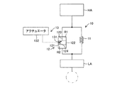
図2は、本実施形態に係るサスペンション装置10を模式的に示した図である。図2に示されるように、サスペンション装置10には、可変絞り機構13が取付けられている。可変絞り機構13は、バルブ131およびアクチュエータ132を有する。バルブ131は、ピストン122に形成された連通路124に設けられていて、公知の絞り機構によって、連通路124の少なくとも一部の流路断面積の大きさ、すなわちバルブ開度OPを変化させる。アクチュエータ132は例えばステッピングモータなどにより構成することができる。図1には、各サスペンション装置10FR,10FL,10RR,10RLに取付けられたアクチュエータ132FR,132FL,132RR,132RLが示されている。これらのアクチュエータは、各サスペンション装置10FR,10FL,10RR,10RLのダンパ12の上部に配置され、バネ上部材HAに固定されている。また、アクチュエータ132は、例えばピストンロッド123の内部に配されるコントロールロッドなどによってバルブ131に連結される。したがって、アクチュエータ132が作動すると、それに伴いバルブ131が作動し、バルブ開度OPが変更される。バルブ開度OPの変更により、連通路124の流路断面積が変更される。その結果、連通路124内を粘性流体が流通するときの抵抗力も変更される。抵抗力の変更により、ダンパ12により発生される減衰力の大きさを表す減衰係数(減衰力特性)が変更される。
FIG. 2 is a diagram schematically showing the
また、図1に示されるように、右前輪側サスペンション装置10FRと左前輪側サスペンション装置10FLは、前輪側スタビライザ14によって連結されている。また、右後輪側サスペンション装置10RRと左後輪側サスペンション装置10RLは、後輪側スタビライザ15によって連結されている。前輪側スタビライザ14および後輪側スタビライザ15は、それぞれ、車両の左右方向に沿って延在するスタビライザバー14a,15aと、これらスタビライザバー14a,15aの両端から連続して延びている一対のスタビライザアーム14b,15bを有する。スタビライザバー14a,15aは、その軸線周りに回転自在にバネ上部材HA(具体的には車体)に支持される。スタビライザアーム14b,15bは、スタビライザバー14a,15aから車両前方に屈曲し、その先端にてバネ下部材LA(具体的にはロアアーム)に接続される。このように設けられる前輪側スタビライザ14および後輪側スタビライザ15は、例えば車両旋回時に発生するロールモーメントを打ち消すアンチロールモーメントを発生し、このアンチロールモーメントにより車両に作用するロールモーメントを低減する機能を有する。
Further, as shown in FIG. 1, the right front wheel side suspension device 10FR and the left front wheel side suspension device 10FL are connected by a front
図3は、電気制御装置20の接続構成を概略的に示す図である。図3に示されるように、電気制御装置20は、サスペンション電子制御ユニット(以下、サスペンションECU)21と、バネ上加速度センサ221FR,221FL,221RR,221RLと、路面上下加速度センサ222FR,222FL,222RR,222RLと、ストロークセンサ223FR,223FL,223RR,223RLと、ロール角加速度センサ224と、ピッチ角加速度センサ225と、車速センサ226と、舵角センサ227と、ヨーレートセンサ228と、駆動回路23FR,23FL,23RR,23RLを備える。
FIG. 3 is a diagram schematically showing a connection configuration of the
バネ上加速度センサ221FR,221FL,221RR,221RLは、バネ上部材HAの各輪位置(右前輪位置,左前輪位置,右後輪位置,左後輪位置)に取付けられており、その位置におけるバネ上部材HAの上下方向に沿った加速度である右前輪側バネ上加速度xb_fr",左前輪側バネ上加速度xb_fl",右後輪側バネ上加速度xb_rr",左後輪側バネ上加速度xb_rl"をそれぞれ検出する。路面上下加速度センサ222FR,222FL,222RR,222RLは、各車輪Wに連結したバネ下部材LAに取付けられており、各バネ下部材LAの上下方向に沿った加速度を計測することにより、各バネ下部材LAが連結されている車輪Wの接地路面の上下方向に沿った加速度である右前輪側路面加速度xr_fr",左前輪側路面加速度xr_fl",右後輪側路面加速度xr_rr",左後輪側路面加速度xr_rl"をそれぞれ検出する。ストロークセンサ223FR,223FL,223RR,223RLは、各サスペンション装置10に取付けられており、サスペンション装置10のストローク変位量、すなわちダンパ12のシリンダ121に対するピストン122の相対変位量を計測することにより、路面に対するバネ上部材HAの変位量である右前輪側バネ上−路面間相対変位量(xr_fr-xb_fr)、左前輪側バネ上−路面間相対変位量(xr_fl-xb_fl)、右後輪側バネ上−路面間相対変位量(xr_rr-xb_rr)、左後輪側バネ上−路面間相対変位量(xr_rl-xb_rl)をそれぞれ検出する。右前輪側バネ上−路面間相対変位量(xr_fr-xb_fr)は、右前輪位置におけるバネ上部材HAの上下方向に沿った基準位置からの変位量である右前輪側バネ上変位量xb_frと、右前輪WFRの接地路面の上下方向に沿った基準位置からの変位量である右前輪側路面変位量xr_frとの差により表される。同様に、左前輪側バネ上−路面間相対変位量(xr_fl-xb_fl)は左前輪側バネ上変位量xb_flと左前輪側路面変位量xr_flとの差、右後輪側バネ上−路面間相対変位量(xr_rr-xb_rr)は右後輪側バネ上変位量xb_rrと右後輪側路面変位量xr_rrとの差、左後輪側バネ上−路面間相対変位量(xr_rl-xb_rl)は左後輪側バネ上変位量xb_rlと左後輪側路面変位量xr_rlとの差により、それぞれ表される。
The sprung acceleration sensors 221FR, 221FL, 221RR, 221RL are attached to the respective wheel positions (right front wheel position, left front wheel position, right rear wheel position, left rear wheel position) of the sprung member HA, and springs at the positions. Right front wheel side sprung acceleration x b_fr ", left rear wheel side sprung acceleration x b_fl ", right rear wheel side sprung acceleration x b_rr ", left rear wheel side sprung acceleration x b_rl "is detected respectively. The road surface vertical acceleration sensors 222FR, 222FL, 222RR, and 222RL are attached to unsprung members LA connected to the wheels W, and by measuring the acceleration along the vertical direction of the unsprung members LA, Right front wheel side road surface acceleration x r_fr ", left front wheel side road surface acceleration x r_fl ", right rear wheel side road surface acceleration x r_rr ", left acceleration which is the acceleration along the vertical direction of the ground road surface of the wheel W to which the member LA is connected The rear wheel side road surface acceleration xr_rl "is detected. Stroke sensors 223FR, 223FL, 223RR, and 223RL are attached to each
ロール角加速度センサ224はバネ上部材HAに取付けられており、バネ上部材HAのロール方向(前後軸周り方向)の角度変位を表すロール角θrの角加速度(ロール角加速度)θr"を検出する。ピッチ角加速度センサ225もバネ上部材HAに取付けられており、バネ上部材HAの左右軸周り方向の角度変位を表すピッチ角θpの角加速度(ピッチ角加速度)θp"を検出する。車速センサ226は車輪Wの近傍に取付けられており、車速パルスをカウントすることにより車速Vを検出する。舵角センサ227は操舵ハンドルに連結したステアリングシャフトに取付けられており、ステアリングシャフトの回転角を計測することにより、転舵輪(一般的には前輪)の転舵角φを検出する。ヨーレートセンサ228はバネ上部材HAに取付けられており、バネ上部材HAの上下軸周りの角速度を表す実ヨーレートYRを検出する。
The roll
サスペンションECU21は、CPU,ROM,RAMなどを主要構成部品とするマイクロコンピュータである。サスペンションECU21の入力側には、上述した各種センサが接続されていて、これらのセンサからの検出信号が入力されるようになっている。このサスペンションECU21は、各種センサからの検出信号に基づいて、後述するプログラムを含む各種プログラムを実行することにより、アクチュエータ132の駆動を制御するための駆動信号を出力する。これによりサスペンション装置10の各ダンパ12により発生される減衰力が制御される。
The
駆動回路23FR,23FL,23RR,23RLは、サスペンションECU21の出力側に接続されている。駆動回路23FR,23FL,23RR,23RLは、それぞれ各サスペンション装置10FR,10FL,10RR,10RLに対応するアクチュエータ132FR,132FL,132RR,132RLに接続されており、サスペンションECU21から出力された駆動信号に基づいて、アクチュエータ132FR,132FL,132RR,132RLに駆動電流を出力する
The drive circuits 23FR, 23FL, 23RR, 23RL are connected to the output side of the
図4は、サスペンションECU21を機能毎に分けて表した図である。図4に示されるように、サスペンションECU21は、後輪近似制御部211と、前輪近似制御部212と、旋回状態判定部213と、統合制御部214を有する。後輪近似制御部211は、後述する後輪近似3輪モデルに基づいて、各サスペンション装置10FR,10FL,10RR,10RLのダンパにより発生されるべき制御目標の減衰力である第1右前輪側要求減衰力F1req_fr,第1左前輪側要求減衰力F1req_fl,第1右後輪側要求減衰力F1req_rr,第1左後輪側要求減衰力F1req_rlを計算し、計算したこれらの要求減衰力を出力する。
FIG. 4 shows the
前輪近似制御部212は、後述する前輪近似3輪モデルに基づいて、各サスペンション装置10FR,10FL,10RR,10RLのダンパにより発生されるべき制御目標の減衰力である第2右前輪側要求減衰力F2req_fr,第2左前輪側要求減衰力F2req_fl,第2右後輪側要求減衰力F2req_rr,第2左後輪側要求減衰力F2req_rlを計算し、計算したこれらの要求減衰力を出力する。
The front wheel
旋回状態判定部213は、後述する旋回状態判定プログラムを実行することにより、現在の車両の旋回状態、具体的には現在の車両の旋回状態がアンダーステア状態であるかオーバーステア状態であるかを判定し、その判定結果を表す旋回状態フラグRSを出力する。
The turning
統合制御部214は、後輪近似制御部211から第1右前輪側要求減衰力F1req_fr,第1左前輪側要求減衰力F1req_fl,第1右後輪側要求減衰力F1req_rr,第1左後輪側要求減衰力F1req_rlを、前輪近似制御部212から第2右前輪側要求減衰力F2req_fr,第2左前輪側要求減衰力F2req_fl,第2右後輪側要求減衰力F2req_rr,第2左後輪側要求減衰力F2req_rlを、旋回状態判定部213から旋回状態フラグRSを入力する。また、入力した値に基づいて、右前輪側サスペンション装置10FRのダンパが発生すべき減衰力である右前輪側要求減衰力Freq_fr、左前輪側サスペンション装置10FLのダンパが発生すべき減衰力である左前輪側要求減衰力Freq_fl、右後輪側サスペンション装置10RRのダンパが発生すべき減衰力である右前輪側要求減衰力Freq_rr、左後輪側サスペンション装置10RLのダンパが発生すべき減衰力である左後輪側要求減衰力Freq_rlを、最終的に決定(選択)する。そして、決定した右前輪側要求減衰力Freq_frに対応する駆動信号を駆動回路23FRに、決定した左前輪側要求減衰力Freq_flに対応する駆動信号を駆動回路23FLに、決定した右後輪側要求減衰力Freq_rlに対応する駆動信号を駆動回路23RRに、決定した左後輪側要求減衰力Freq_rlに対応する駆動信号を駆動回路23RLに、それぞれ出力する。
The
上記構成のサスペンション制御装置1において、バネ上加速度センサ221FR,221FL,221RR,221RLの検出値から得られる各輪位置におけるバネ上加速度のいずれか一つが所定の閾値を越えた場合、サスペンションECU21の後輪近似制御部211は後輪近似制御プログラムを、前輪近似制御部212は前輪近似制御プログラムを、旋回状態判定部213は旋回状態判定プログラムを、統合制御部214は統合制御プログラムを、それぞれ実行する。
In the
図5は、後輪近似制御プログラムの流れを示すフローチャートである。後輪近似制御部211は、この後輪近似制御プログラムを図5のステップ(以下、ステップ番号をSと略記する)100にて開始する。次いで、S102にて、バネ上加速度センサ221FR,221FL,221RR,221RLから右前輪側バネ上加速度xb_fr",左前輪側バネ上加速度xb_fl",右後輪側バネ上加速度xb_rr",左後輪側バネ上加速度xb_rl"を、路面上下加速度センサ222FR,222FL,222RR,222RLから右前輪側路面加速度xr_fr",左前輪側路面加速度xr_fl",右後輪側路面加速度xr_rr",左後輪側路面加速度xr_rl"を、ストロークセンサ223FR,223FL,223RR,223RLから右前輪側バネ上−路面間相対変位量(xr_fr-xb_fr),左前輪側バネ上−路面間相対変位量(xr_fl-xb_fl),右後輪側バネ上−路面間相対変位量(xr_rr-xb_rr),左後輪側バネ上−路面間相対変位量(xr_rl-xb_rl)を、ロール角加速度センサ224からロール角加速度θr"を、ピッチ角加速度センサ225からピッチ角加速度θp"を、それぞれ入力する。
FIG. 5 is a flowchart showing the flow of the rear wheel approximation control program. The rear wheel
次に、S104にて、右前輪側バネ上加速度xb_fr"を時間積分することにより、右前輪位置におけるバネ上部材HAの上下方向に沿った速度である右前輪側バネ上速度xb_fr'を、左前輪側バネ上加速度xb_fl"を時間積分することにより左前輪側バネ上速度xb_fl'を計算する。また、右後輪側バネ上加速度xb_rr"を時間積分して右後輪側バネ上速度xb_rr'を、左後輪側バネ上加速度xb_rl"を時間積分して左後輪側バネ上速度xb_rl'を計算し、さらに、これらの速度xb_rr'およびxb_rl'を足して2で割ることにより、後方中心輪側バネ上速度xb_R'を計算する。 Next, in S104, right front wheel side sprung acceleration x b_fr ”is integrated over time to obtain right front wheel side sprung speed x b_fr ′ which is the speed along the vertical direction of sprung member HA at the right front wheel position. , calculates the left front wheel on the side spring rate x b_fl 'by time integration of the acceleration x b_fl "on the left front wheel-side spring. Also, right rear wheel side sprung acceleration x b_rr "is time integrated to right rear wheel side sprung speed x b_rr 'and left rear wheel side sprung acceleration x b_rl " is time integrated to left rear wheel side sprung 'calculates the further these speeds x B_rr' rate x B_rl 'by dividing by 2 by adding the velocity on the rear center wheel spring x B_R' and x B_rl calculated.
また、右前輪側バネ上速度xb_fr'をさらに時間積分することにより、右前輪位置におけるバネ上部材HAの上下方向に沿った基準位置からの変位量である右前輪側バネ上変位量xb_frを、左前輪側バネ上速度xb_fl'をさらに時間積分することにより左前輪側バネ上変位量xb_flを計算する。また、後方中心輪側バネ上速度xb_R'をさらに時間積分することにより後方中心輪側バネ上変位量xb_Rを計算する。 Further, the right front wheel side sprung speed x b_fr ′ is further integrated over time, so that the right front wheel side sprung displacement x b_fr which is a displacement amount from the reference position along the vertical direction of the sprung member HA at the right front wheel position. The left front wheel side sprung speed x b_fl ′ is further integrated over time to calculate the left front wheel side sprung displacement x b_fl . Further, the rear center wheel side sprung speed x b_R ′ is further integrated over time to calculate the rear center wheel side sprung displacement x b_R .
続いて、S106にて、右前輪側路面加速度xr_fr"を時間積分することにより、右前輪WFRの接地路面の上下方向に沿った変位速度である右前輪側路面速度xr_fr'を、左前輪側路面加速度xr_fl"を時間積分することにより左前輪側路面速度xr_fl'を計算する。また、右後輪側路面加速度xr_rr"を時間積分して右後輪側路面速度xr_rr'を、左後輪側路面加速度xr_rl"を時間積分して左後輪側路面速度xr_rl'を計算し、さらに、これらの速度xr_rr'およびxr_rl'を足して2で割ることにより、後方中心輪側路面速度xr_R'を計算する。 Subsequently, at S106, the right front wheel side road surface acceleration xr_fr "is time-integrated to obtain the right front wheel side road surface speed xr_fr 'which is the displacement speed along the vertical direction of the ground contact road surface of the right front wheel WFR. The left front wheel side road surface speed x r_fl ′ is calculated by integrating the side road surface acceleration x r_fl ”over time. In addition, the right rear wheel side road surface acceleration x r_rr "is time-integrated to obtain the right rear wheel side road surface speed x r_rr ', and the left rear wheel side road surface acceleration x r_rl " is time integrated to obtain the left rear wheel side road surface speed x r_rl '. was calculated, further, by dividing by 2 by adding these velocity x r_rr 'and x r_rl', calculates a rear center wheel side road surface velocity x r_r '.
また、右前輪側路面速度xr_fr'をさらに時間積分することにより、右前輪WFRの接地路面の上下方向に沿った基準位置からの変位量である右前輪側路面変位量xr_frを、左前輪側路面速度xr_fl'をさらに時間積分することにより左前輪側路面変位量xb_flを計算する。また、後方中心輪側路面速度xr_R'をさらに時間積分することにより後方中心輪側路面変位量xr_Rを計算する。 Further, the right front wheel side road surface speed x r_fr ′ is further integrated over time, so that the right front wheel side road surface displacement amount x r_fr , which is a displacement amount from the reference position along the vertical direction of the ground road surface of the right front wheel WFR, is converted into the left front wheel. The left front wheel side road surface displacement x b_fl is calculated by further integrating the side road surface speed x r_fl ′ over time. Further, the rear center wheel side road surface displacement xr_R ′ is further time integrated to calculate the rear center wheel side road surface displacement amount xr_R .
次いで、S108にて、右前輪側バネ上−路面間相対変位量(xr_fr-xb_fr)を時間微分することにより、右前輪側バネ上速度xb_fr'と右前輪側路面速度xr_fr'との差により表される右前輪側バネ上−路面間相対速度(xr_fr'-xb_fr')を、左前輪側バネ上−路面間相対変位量(xr_fl-xb_fl)を時間微分することにより左前輪側バネ上−路面間相対速度(xr_fl'-xb_fl')を計算する。また、右後輪側バネ上−路面間相対変位量(xr_rr-xb_rr)を時間微分して右後輪側バネ上−路面間相対速度(xr_rr'-xb_rr')を、左後輪側バネ上−路面間相対変位量(xr_rl-xb_rl)を時間微分して左後輪側バネ上−路面間相対速度(xr_rl'-xb_rl')を計算し、さらに、これらの速度(xr_rr'-xb_rr')および(xr_rl'-xb_rl')を足して2で割ることにより、後方中心輪側バネ上−路面間相対速度(xr_R'-xb_R')を計算する。この後方中心輪側バネ上−路面間相対速度(xr_R'-xb_R')は、後方中心輪側バネ上速度xb_R'と後方中心輪側路面速度xr_R'との差である。 Next, at S108, the right front wheel side sprung speed x b_fr ′ and the right front wheel side road speed x r_fr ′ are obtained by time differentiation of the relative displacement (x r_fr −x b_fr ) between the right front wheel sprung and road surface. The right front wheel side sprung-road relative speed (x r_fr '-x b_fr ') and the left front wheel side sprung-road relative displacement (x r_fl -x b_fl ) expressed by the difference The left front wheel side sprung-road relative speed (x r_fl '-x b_fl ') is calculated. Also, the right rear wheel side sprung-road relative displacement (x r_rr -x b_rr ) is time-differentiated to obtain the right rear wheel side sprung-road relative speed (x r_rr '-x b_rr '). Relative displacement amount between wheel side sprung and road surface (x r_rl -x b_rl ) is time differentiated to calculate left rear wheel side sprung-road relative speed (x r_rl '-x b_rl '). Add the speed (x r_rr '-x b_rr ') and (x r_rl '-x b_rl ') and divide by 2 to obtain the rear center wheel side sprung-road relative speed (x r_R '-x b_R ') calculate. This rear center wheel side sprung-road relative speed (x r_R '-x b_R ') is the difference between the rear center wheel side sprung speed x b_R 'and the rear center wheel side road surface speed x r_R '.
次に、後輪近似制御部211は、S110にて、非線形H∞制御理論を適用し、右前輪側可変減衰係数Cv_fr,左前輪側可変減衰係数Cv_fl,後方中心輪側可変減衰係数Cv_Rを計算する。この計算をする際に、図9に示される後輪近似3輪モデルが力学的な運動モデルとして用いられる。この後輪近似3輪モデルは、右後輪側サスペンション装置10RRおよび左後輪側サスペンション装置10RLが1個の後方中心輪側サスペンション装置10Rに置き換えられ、バネ上部材HAが、前輪側に位置する2個のサスペンション装置10FR,10FLおよび、後輪中央部に位置する1個のサスペンション装置10Rにより支えられている車両の運動を表す車両モデルである。後方中心輪側サスペンション装置10Rは、バネ上部材HAの右後輪位置と左後輪位置を結ぶ後輪軸の中心位置にてバネ上部材HAに仮想的に取付けられる。なお、S104にて計算された後方中心輪側バネ上速度xb_R'および後方中心輪側バネ上変位量xb_Rは、後方中心輪側サスペンション装置10Rがバネ上部材HAに取付けられている位置(後方中心輪位置)における、バネ上部材HAの上下方向に沿った速度および変位量である。また、S106にて計算された後方中心輪側路面速度xr_R'および後方中心輪側路面変位量xr_Rは、後方中心輪側サスペンション装置10Rに連結すべき車輪(後方中心輪)の接地路面の上下方向に沿った速度および変位量である。後方中心輪側サスペンション装置10Rが本発明の仮想サスペンション装置および後輪側仮想サスペンション装置に相当する。
Next, in S110, the rear wheel
また、図9の後輪近似3輪モデルにおいて、右前輪側サスペンション装置10FRのバネのバネ定数がKs_frにより、左前輪側サスペンション装置10FLのバネのバネ定数がKs_flにより、後方中心輪側サスペンション装置10Rのバネのバネ定数がKs_Rにより表される。バネ定数Ks_Rは、例えば、右後輪側サスペンション装置10RRのバネのバネ定数Ks_rrと左後輪側サスペンション装置10RLのバネのバネ定数Ks_rlの平均により表すことができる。
Further, in the rear wheel approximate three-wheel model of FIG. 9, the spring constant of the spring of the right front wheel side suspension device 10FR is K s_fr and the spring constant of the spring of the left front wheel side suspension device 10FL is K s_fl. The spring constant of the spring of the
また、右前輪側サスペンション装置10FRのダンパの減衰係数が、右前輪側線形減衰係数Cs_frと右前輪側可変減衰係数Cv_frとの和(Cs_fr+Cv_fr)により表される。右前輪側線形減衰係数Cs_frは変動しない減衰係数を表し、右前輪側可変減衰係数Cv_frは変動する減衰係数を表す。また、左前輪側サスペンション装置10FLのダンパの減衰係数が、左前輪側線形減衰係数Cs_flと左前輪側可変減衰係数Cv_flの和(Cs_fl+Cv_fl)により表される。左前輪側線形減衰係数Cs_flは変動しない減衰係数を表し、左前輪側可変減衰係数Cv_flは変動する減衰係数を表す。また、後方中心輪側サスペンション装置10Rのダンパの減衰係数が、後方中心輪側線形減衰係数Cs_Rと後方中心輪側可変減衰係数Cv_Rとの和(Cs_R+Cv_R)により表される。後方中心輪側線形減衰係数Cs_Rは変動しない減衰係数を表し、後方中心輪側可変減衰係数Cv_Rは変動する減衰係数を表す。各線形減衰係数Cs_fr,Cs_fl,Cs_Rは予め定められる。後方中心輪側線形減衰係数Cs_Rは、例えば右後輪側サスペンション装置10RRのダンパについて予め定められる右後輪側線形減衰係数Cs_rrと左後輪側サスペンション装置10RLのダンパについて予め定められる左後輪側線形減衰係数Cs_rlの平均により表すことができる。また、前輪側スタビライザ14により発生される捩り力の係数である前輪側捩り弾性係数がKstb_Fにより表される。
Further, the damping coefficient of the damper of the right front wheel side suspension device 10FR is represented by the sum (C s_fr + C v_fr ) of the right front wheel side linear damping coefficient C s_fr and the right front wheel side variable damping coefficient C v_fr . The right front wheel side linear damping coefficient C s_fr represents a damping coefficient that does not vary, and the right front wheel side variable damping coefficient C v_fr represents a varying damping coefficient. Further, the damping coefficient of the damper of the left front wheel side suspension apparatus 10FL is represented by the sum (C s_fl + C v_fl ) of the left front wheel side linear damping coefficient C s_fl and the left front wheel side variable damping coefficient C v_fl . The left front wheel side linear damping coefficient C s_fl represents a damping coefficient that does not vary, and the left front wheel side variable damping coefficient C v_fl represents a varying damping coefficient. Further, the damping coefficient of the damper of the rear center wheel
そして、S110にて、後輪近似制御部211は、後輪近似3輪モデルから導き出された運動方程式に基づいて設計された制御システムに非線形H∞制御理論を適用し、モデルに表されている3個のサスペンション装置10FR,10FL,10Rの各可変減衰係数(右前輪側可変減衰係数Cv_fr,左前輪側可変減衰係数Cv_fl,後方中心輪側可変減衰係数Cv_R)を計算する。
In S110, the rear wheel
後輪近似3輪モデルから導き出されるバネ上部材HAの運動方程式は、下記式(eq.1)〜式(eq.3)のように表される。
![]()
![]()
![]()
![]()
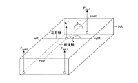
式(eq.1)は、バネ上部材HAの上下方向の運動方程式(ヒーブ運動方程式)、式(eq.2)は、バネ上部材HAのローリング方向(前後軸周りの回転方向)の運動方程式(ロール運動方程式)、式(eq.3)は、バネ上部材HAのピッチング方向(左右軸周りの回転方向)の運動方程式(ピッチ運動方程式)である。上式において、Mbはバネ上部材HAの質量、xh"はバネ上部材HAの重心位置における上下方向に沿った加速度(ヒーブ加速度)である。ヒーブ加速度xh"は、各バネ上加速度センサ221FR,221FL,221RR,221RLにより検出されるバネ上加速度から求めることができる。Fsus_frはバネ上部材HAの右前輪位置にてバネ上部材HAに上下方向に作用する力(右前輪側上下力)、Fsus_flはバネ上部材HAの左前輪位置にてバネ上部材HAに上下方向に作用する力(左前輪側上下力)、Fsus_Rはバネ上部材HAの後方中心輪位置にてバネ上部材HAに上下方向に作用する力(後方中心輪側上下力)である。図10は、式(eq.1)〜(eq.3)に表される上下力の作用位置や加速度を表した図である。 Equation (eq.1) is the equation of motion of the sprung member HA in the vertical direction (heave equation of motion), and equation (eq.2) is the equation of motion of the sprung member HA in the rolling direction (rotational direction around the longitudinal axis). (Roll motion equation), equation (eq.3) is a motion equation (pitch motion equation) of the sprung member HA in the pitching direction (rotational direction around the left-right axis). In the above equation, M b is the mass of the sprung member HA, x h ″ is the acceleration along the vertical direction (heave acceleration) at the center of gravity of the sprung member HA. Heave acceleration x h ″ is each sprung acceleration. It can be obtained from the sprung acceleration detected by the sensors 221FR, 221FL, 221RR, 221RL. F sus_fr is a force acting vertically on the sprung member HA at the right front wheel position of the sprung member HA (right front wheel side vertical force), and F sus_fl is applied to the sprung member HA at the left front wheel position of the sprung member HA. The force acting in the vertical direction (left front wheel side vertical force), F sus_R is the force acting in the vertical direction on the sprung member HA at the rear central wheel position of the sprung member HA (rear central wheel side vertical force). FIG. 10 is a diagram showing the applied position and acceleration of the vertical force expressed by the equations (eq.1) to (eq.3).
また、上式において、Irはバネ上部材HAのローリング方向の慣性モーメント(ロールイナーシャ)、Ipはバネ上部材HAのピッチング方向の慣性モーメント(ピッチイナーシャ)、Tfは前輪側のトレッドである。Lfは、バネ上部材HAの重心位置から右前輪位置と左前輪位置とを結ぶ前輪軸までの前後方向距離である。Lrは、バネ上部材HAの重心位置から後方中心輪位置までの前後方向距離である。 Further, in the above equation, I r is the moment of inertia (roll inertia) of the rolling direction of the sprung member HA, pitching direction of the inertia moment (pitch inertia) of I p is sprung member HA, T f is a front wheel tread is there. L f is a longitudinal distance from the center of gravity position of the sprung member HA to the front wheel axis connecting the right front wheel position and the left front wheel position. L r is the distance in the front-rear direction from the position of the center of gravity of the sprung member HA to the position of the rear center wheel.
右前輪側上下力Fsus_frは下記式(eq.4)により、左前輪側上下力Fsus_flは下記式(eq.5)により、後方中心輪側上下力Fsus_Rは下記式(eq.6)により表される。
![]()
![]()
![]()
![]()
![]()
![]()
上記式(eq.4)〜(eq.6)において、Fsp_frは右前輪側サスペンション装置10FRのバネにより発生される弾性力(右前輪側弾性力)、Fsp_flは左前輪側サスペンション装置10FLのバネにより発生される弾性力(左前輪側弾性力)、Fsp_Rは後方中心輪側サスペンション装置10Rのバネにより発生される弾性力(後方中心輪側弾性力)である。FCs_frは右前輪側サスペンション装置10FRのダンパにより発生される減衰力のうち、右前輪側線形減衰係数Cs_frにより表される減衰力(右前輪側線形減衰力)、FCv_frは右前輪側可変減衰係数Cv_frにより表される減衰力(右前輪側可変減衰力)である。FCs_flは左前輪側サスペンション装置10FLのダンパにより発生される減衰力のうち、左前輪側線形減衰係数Cs_flにより表される減衰力(左前輪側線形減衰力)、FCv_flは左前輪側可変減衰係数Cv_flにより表される減衰力(左前輪側可変減衰力)である。FCs_Rは後方中心輪側サスペンション装置10Rのダンパにより発生される減衰力のうち、後方中心輪側線形減衰係数Cs_Rにより表される減衰力(後方中心輪側線形減衰力)、FCv_Rは後方中心輪側可変減衰係数Cv_Rにより表される減衰力(後方中心輪側可変減衰力)である。Fstb_Fは、前輪側スタビライザ14により発生される捩り弾性力(前輪側捩り弾性力)である。
In the above equations (eq.4) to (eq.6), F sp_fr is the elastic force (right front wheel side elastic force) generated by the spring of the right front wheel side suspension device 10FR, and F sp_fl is the left front wheel side suspension device 10FL. The elastic force (left front wheel side elastic force) generated by the spring and F sp_R is the elastic force (rear center wheel side elastic force) generated by the spring of the rear central wheel
右前輪側弾性力Fsp_fr、左前輪側弾性力Fsp_flおよび後方中心輪側弾性力Fsp_Rは、下記式(eq.7)〜(eq.9)により表される。
![]()
![]()
![]()
![]()
![]()
![]()
右前輪側線形減衰力FCs_fr、左前輪側線形減衰力FCs_flおよび後方中心輪側線形減衰力FCs_Rは、下記式(eq.10)〜(eq.12)により表される。
![]()
![]()
![]()
![]()
![]()
![]()
右前輪側可変減衰力FCv_fr、左前輪側可変減衰力FCv_flおよび後方中心輪側可変減衰力FCv_Rは、下記式(eq.13)〜(eq.15)により表される。
![]()
![]()
![]()
![]()
![]()
![]()
前輪側捩り弾性力Fstb_Fは、下記式(eq.16)により表される。
![]()
![]()
また、バネ上部材HAの重心位置における上下変位量を表すヒーブ変位量xh、ロール角θrおよびピッチ角θpは、下記式(eq.17)に示されるように、モード変換行列を用いて、右前輪側バネ上変位量xb_fr、左前輪側バネ上変位量xb_fl、後方中心輪位置におけるバネ上変位量(前方中心輪側バネ上変位量)xb_Rに変換することができる。
以上の関係式から、後輪近似3輪モデルの状態空間表現が、下記式(eq.18)のように表される。
上記式(eq.18)において、状態量xp,評価出力zp,外乱wは、例えば下記式(eq.19)のように表される。
また、制御入力uは、下記式(eq.20)に示されるように、右前輪側可変減衰係数Cv_fr、左前輪側可変減衰係数Cv_flおよび後方中心輪側可変減衰係数Cv_Rである。
また、Ap,BP1,Bp2(xp),Cp1,Dp12(xp)は係数行列である。これらの係数行列は、状態量xp,評価出力zp,外乱wが上記(eq.19)のように設定され、且つ制御入力uが上記式(eq.20)のように設定されたときに、式(eq.1)〜(eq.3)の運動方程式を満たすように定められる。 A p , B P1 , B p2 (x p ), C p1 , and D p12 (x p ) are coefficient matrices. These coefficient matrices are obtained when the state quantity x p , the evaluation output z p , and the disturbance w are set as in (eq.19) above, and the control input u is set as in the above equation (eq.20). Are defined to satisfy the equations of motion of equations (eq.1) to (eq.3).
表2に、式(eq.18)に示された状態空間表現中の操作量(制御入力u)の個数、状態量の個数、状態空間表現の基礎となる後輪近似3輪モデルの自由度を示す。
表2に示されるように、後輪近似3輪モデルにより表されるバネ上部材の自由度は3自由度(上下運動、ロール運動、ピッチ運動)である。また、本モデルにおいてバネ下部材の運動は考慮しない。つまりバネ下部材が路面と同じように上下変位する。このためサスペンション装置の自由度は1自由度(バネ上部材の上下運動)である。したがって、このモデルの自由度は3自由度である。また、システムの外乱は、式(eq.19)に示されるように3輪(右前輪、左前輪、後方中心輪)の路面変位量xr_fr,xr_fl,xr_Rである。この外乱をバネ上部材HAの変位にモード変換すると、外乱は、バネ上部材HAの上下変位、ロール変位、ピッチ変位により表される。したがって、外乱によるバネ上部材HAの自由度は3自由度である。モデルの自由度と外乱によるバネ上部材HAの自由度が等しいため、この制御システムは可制御である。 As shown in Table 2, the degree of freedom of the sprung member represented by the rear wheel approximate three-wheel model is three degrees of freedom (vertical motion, roll motion, pitch motion). Further, in this model, the movement of the unsprung member is not considered. That is, the unsprung member is displaced up and down like the road surface. For this reason, the degree of freedom of the suspension device is one degree of freedom (up-and-down motion of the sprung member). Therefore, this model has 3 degrees of freedom. Further, the disturbance of the system is the road surface displacement amounts x r_fr , x r_fl , x r_R of the three wheels (the right front wheel, the left front wheel, and the rear center wheel) as shown in the equation (eq.19). When this disturbance is mode-converted into the displacement of the sprung member HA, the disturbance is expressed by the vertical displacement, roll displacement, and pitch displacement of the sprung member HA. Therefore, the degree of freedom of the sprung member HA due to disturbance is 3 degrees of freedom. Since the degree of freedom of the model and the degree of freedom of the sprung member HA due to disturbance are equal, this control system is controllable.
図11は、上記式(eq.18)に示される状態空間表現に基づいて設計された一般化プラント(制御システム)のブロック線図である。図に示されるように、評価出力zpと制御入力uに周波数重みWs(s),Wu(s)がそれぞれ作用している。なお、この出力にさらに非線形重みが作用するように、システムを設計してもよい。 FIG. 11 is a block diagram of a generalized plant (control system) designed based on the state space expression shown in the above equation (eq.18). As shown in the figure, frequency weights W s (s) and W u (s) act on the evaluation output z p and the control input u, respectively. It should be noted that the system may be designed so that a nonlinear weight further acts on this output.
周波数重みWs(s)の状態空間表現は、周波数重みWs(s)の状態量xw、出力zwおよび各定数行列Aw,Bw,Cw,Dwにより、下記式(eq.21)のように表される。また、周波数重みWu(s)の状態空間表現は、周波数重みWu(s)の状態量xu、出力zuおよび各定数行列Au,Bu,Cu,Duにより、下記式(eq.22)のように表される。
一般化プラントの状態空間表現は、式(eq.18),(eq.21),(eq.22)を用いることにより、下記式(eq.23)のように表すことができる。
式(eq.23)は、双線形システムである。したがって、このシステムの制御則u=k(x)は、ハミルトンヤコビ偏微分不等式を解くかわりに、近似的に下記式(eq.24)に示されるリカッチ不等式を解くことにより、得られる。
上記式(eq.24)により表されるリカッチ不等式を満たす正定対称行列Pが存在する場合、図11に示される一般化プラントの閉ループシステムが内部安定となり、且つ、外乱wに対するロバスト性を表すL2ゲインが正定数γ以下となる。このとき制御入力u(=k(x))は、例えば下記式(eq.25)のように表される。
![]()
![]()
したがって、S110において、後輪近似制御部211は、式(eq.25)に基づいて制御入力uを求めることにより、各可変減衰係数Cv_fr,Cv_fl,Cv_Rを得ることができる。
Therefore, in S110, the rear wheel
可変減衰係数を計算した後、後輪近似制御部211は図5のS112に進み、第1右前輪側要求減衰力F1req_fr,第1左前輪側要求減衰力F1req_fl,第1後方中心輪側要求減衰力F1req_Rを計算する。これらの要求減衰力は、後輪近似3輪モデルに表される各サスペンション装置のダンパにより発生されるべき制御目標の減衰力(要求減衰力)である。第1右前輪側要求減衰力F1req_frは、後輪近似3輪モデルに表される右前輪側サスペンション装置10FRについての要求減衰力であり、右前輪側線形減衰係数Cs_frと右前輪側可変減衰係数Cv_frとの和(Cs_fr+Cv_fr)に右前輪側バネ上−路面間相対速度(xr_fr'-xb_fr')を乗じることにより計算される。第1左前輪側要求減衰力F1req_flは、後輪近似3輪モデルに表される左前輪側サスペンション装置10FLについての要求減衰力であり、左前輪側線形減衰係数Cs_flと左前輪側可変減衰係数Cv_flとの和(Cs_fl+Cv_fl)に左前輪側バネ上−路面間相対速度(xr_fl'-xb_fl')を乗じることにより計算される。第1後方中心輪側要求減衰力F1req_Rは、後輪近似3輪モデルに表される後方中心輪側サスペンション装置10Rについての要求減衰力であり、後方中心輪側線形減衰係数Cs_Rと後方中心輪側可変減衰係数Cv_Rとの和(Cs_R+Cv_R)に後方中心輪側バネ上−路面間相対速度(xr_R'-xb_R')を乗じることにより計算される。S112にて後輪近似3輪モデルに表される3個のサスペンション装置10FR,10FL,10Rについての要求減衰力を計算する処理が、本発明のモデル要求減衰力計算手段に相当する。
After calculating the variable damping coefficient, the rear wheel
次に、後輪近似制御部211は、S114にて、第1後方中心輪側要求減衰力F1req_Rを第1右後輪側要求減衰力F1req_rrおよび第1左後輪側要求減衰力F1req_rlに分配する。具体的には、第1後方中心輪側要求減衰力F1req_Rを2で割ることにより、第1右後輪側要求減衰力F1req_rrおよび第1左後輪側要求減衰力F1req_rlを計算する。第1右後輪側要求減衰力F1req_rrは、後輪近似3輪モデルに基づいて計算される右後輪側サスペンション装置10RRについての要求減衰力であり、第1左後輪側要求減衰力F1req_rlは左後輪側サスペンション装置10RLについての要求減衰力である。本実施形態のように後方中心輪側サスペンション装置10Rの取付位置が右後輪側サスペンション装置10RRの取付位置と左後輪側サスペンション装置10RLの取付位置の中間に位置している場合、第1右後輪側要求減衰力F1req_rrの大きさと第1左後輪側要求減衰力F1req_rlの大きさが等しくなるように、つまり分配比率が1:1になるように、第1後方中心輪側要求減衰力F1req_Rが第1右後輪側要求減衰力F1req_rrと第1左後輪側要求減衰力F1req_rlに分配される。このS114にて行われる処理が、本発明の要求減衰力分配手段に相当する。
Next, in S114, the rear wheel
S114にて第1右後輪側要求減衰力F1req_rrおよび第1左後輪側要求減衰力F1req_rlを計算した後、後輪近似制御部211はS116に進み、第1右前輪側要求減衰力F1req_rl,第1左前輪側要求減衰力F1req_rl,第1右後輪側要求減衰力F1req_rl,第1左後輪側要求減衰力F1req_rlを出力する。その後、S118に進んでこのプログラムを終了する。以上の説明からわかるように、本実施形態の後輪近似制御部211は、後輪近似3輪モデルから導出されるバネ上部材HAの上下運動、ロール運動およびピッチ運動に基づいて設計される制御システムに非線形H∞制御理論を適用することにより、後輪近似3輪モデルに表される3個のサスペンション装置についての要求減衰力を計算する。また、計算した要求減衰力のうち後方中心輪側サスペンション装置10Rについての要求減衰力(第1後方中心輪側要求減衰力F1req_R)を、この後方中心輪側サスペンション装置10Rに置き換えられた右後輪側サスペンション装置10RRおよび左後輪側サスペンション装置10RLについての要求減衰力(第1右後輪側要求減衰力F1req_rrおよび第1左後輪側要求減衰力F1req_rl)に分配する。これにより、バネ上部材HAの各輪位置に取付けられた4個のサスペンション装置についての要求減衰力が計算される。この後輪近似制御部211が、本発明の第1要求減衰力計算手段に相当する。
After calculating the first right rear wheel side required damping force F1 req_rr and the first left rear wheel side required damping force F1 req_rl in S114 , the rear wheel
図6は、前輪近似制御プログラムの流れを示すフローチャートである。前輪近似制御部212は、この前輪近似制御プログラムを図6のS200にて開始する。次いで、S202にて、バネ上加速度センサ221FR,221FL,221RR,221RLから右前輪側バネ上加速度xb_fr",左前輪側バネ上加速度xb_fl",右後輪側バネ上加速度xb_rr",左後輪側バネ上加速度xb_rl"を、路面上下加速度センサ222FR,222FL,222RR,222RLから右前輪側路面加速度xr_fr",左前輪側路面加速度xr_fl",右後輪側路面加速度xr_rr",左後輪側路面加速度xr_rl"を、ストロークセンサ223FR,223FL,223RR,223RLから右前輪側バネ上−路面間相対変位量(xr_fr-xb_fr),左前輪側バネ上−路面間相対変位量(xr_fl-xb_fl),右後輪側バネ上−路面間相対変位量(xr_rr-xb_rr),左後輪側バネ上−路面間相対変位量(xr_rl-xb_rl)を、ロール角加速度センサ224からロール角加速度θr"を、ピッチ角加速度センサ225からピッチ角加速度θp"を、それぞれ入力する。
FIG. 6 is a flowchart showing the flow of the front wheel approximate control program. The front wheel
次に、S204にて、右前輪側バネ上加速度xb_fr"を時間積分することにより右前輪側バネ上速度xb_fr'を、左前輪側バネ上加速度xb_fl"を時間積分することにより左前輪側バネ上速度xb_fl'を計算し、さらにこれらの速度xb_fr'およびxb_fl'を足して2で割ることにより、前輪中心輪側バネ上速度xb_F'を計算する。また、右後輪側バネ上加速度xb_rr"を時間積分して右後輪側バネ上速度xb_rr'を、左後輪側バネ上加速度xb_rl"を時間積分して左後輪側バネ上速度xb_rl'を計算する。 Then, the left front wheel by at S204, "the speed on the front-right wheel-side spring x b_fr 'by time integrating the acceleration x B_fl on the left front wheel-side spring" on the right front wheel-side spring acceleration x B_fr to time integration of the The side sprung speed x b_fl ′ is calculated, and these speeds x b_fr ′ and x b_fl ′ are added and divided by two to calculate the front wheel center wheel side sprung speed x b_F ′. Also, right rear wheel side sprung acceleration x b_rr "is time integrated to right rear wheel side sprung speed x b_rr 'and left rear wheel side sprung acceleration x b_rl " is time integrated to left rear wheel side sprung Calculate velocity x b_rl '.
また、右後側バネ上速度xb_rr'をさらに時間積分することにより、右後輪位置におけるバネ上部材HAの上下方向に沿った基準位置からの変位量である右後輪側バネ上変位量xb_rrを、左後輪側バネ上速度xb_rl'をさらに時間積分することにより左後輪側バネ上変位量xb_rlを計算する。また、前方中心輪側バネ上速度xb_F'をさらに時間積分することにより前方中心輪側バネ上変位量xb_Fを計算する。 Further, the right rear wheel sprung speed x b_rr ′ is further integrated over time, so that the right rear wheel sprung displacement amount, which is the displacement amount from the reference position along the vertical direction of the sprung member HA at the right rear wheel position, is obtained. The left rear wheel side sprung displacement amount x b_rl is calculated by further integrating x b_rr with the left rear wheel side sprung speed x b_rl 'over time. Further, the front center wheel side sprung speed x b_F ′ is further integrated over time to calculate the front center wheel side sprung displacement x b_F .
続いて、S206にて、右前輪側路面加速度xr_fr"を時間積分することにより右前輪側路面速度xr_fr'を、左前輪側路面加速度xr_fl"を時間積分することにより左前輪側路面速度xr_fl'を計算し、さらにこれらの速度xr_fr'およびxr_fl"を足して2で割ることにより、前方中心輪側路面速度xr_F'を計算する。また、右後輪側路面加速度xr_rr"を時間積分して右後輪側路面速度xr_rr'を、左後輪側路面加速度xr_rl"を時間積分して左後輪側路面速度xr_rl'を計算する。 Subsequently, in S206, the right front wheel side road surface speed xr_fr "is time-integrated to integrate the right front wheel side road surface speed xr_fr ', and the left front wheel side road surface acceleration xr_fl " is integrated to time. x r_fl ′ is calculated, and these speeds x r_fr ′ and x r_fl ″ are added and divided by two to calculate the front center wheel side road speed x r_F ′. Also, the right rear wheel side road acceleration x r_rr Time integration is performed to calculate the right rear wheel side road surface speed xr_rr 'and the left rear wheel side road surface acceleration xr_rl "to time integration to calculate the left rear wheel side road surface speed xr_rl '.
また、右後輪側路面速度xr_rr'をさらに時間積分することにより、右後輪WRRの接地路面の上下方向に沿った基準位置からの変位量である右後輪側路面変位量xr_rrを、左後輪側路面速度xr_rl'をさらに時間積分することにより左後輪側路面変位量xr_rlを計算する。また、前方中心輪側路面速度xr_F'をさらに時間積分することにより前方中心輪側路面変位量xr_Fを計算する。 Further, the right rear wheel side road surface speed xr_rr ′ is further integrated over time to obtain the right rear wheel side road surface displacement amount xr_rr which is a displacement amount from the reference position along the vertical direction of the ground road surface of the right rear wheel WRR. , calculates the left rear wheel side road surface displacement x R_rl by further time integration of the left rear wheel side road surface velocity x r_rl '. Further, the front center wheel side road surface displacement x r_F 'is further integrated over time to calculate the front center wheel side road surface displacement amount x r_F .
次いで、S208にて、右前輪側バネ上−路面間相対変位量(xr_fr-xb_fr)を時間微分することにより右前輪側バネ上−路面間相対速度(xr_fr'-xb_fr')を、左前輪側バネ上−路面間相対変位量(xr_fl-xb_fl)を時間微分することにより左前輪側バネ上−路面間相対速度(xr_fl'-xb_fl')を計算し、さらに、これらの速度(xr_fr'-xb_fr')および(xr_fl'-xb_fl')を足して2で割ることにより、前方中心輪側バネ上−路面間相対速度(xr_F'-xb_F')を計算する。この前方中心輪側バネ上−路面間相対速度(xr_F'-xb_F')は、前方中心輪側バネ上速度xb_F'と前方中心輪側路面速度xr_F'との差である。また、右後輪側バネ上−路面間相対変位量(xr_rr-xb_rr)を時間微分して右後輪側バネ上−路面間相対速度(xr_rr'-xb_rr')を、左後輪側バネ上−路面間相対変位量(xr_rl-xb_rl)を時間微分して左後輪側バネ上−路面間相対速度(xr_rl'-xb_rl')を計算する。 Next, in S208, the right front wheel side sprung-road relative speed (x r_fr '-x b_fr ') is obtained by time-differentiating the right front wheel side sprung-road relative displacement amount (x r_fr -x b_fr ). The left front wheel side sprung-road relative speed (x r_fl '-x b_fl ') is calculated by differentiating the left front wheel side sprung-road relative displacement (x r_fl -x b_fl ) with respect to time. By adding these speeds (x r_fr '-x b_fr ') and (x r_fl '-x b_fl ') and dividing by 2, the relative speed between the front center wheel side sprung and road surface (x r_F '-x b_F ' ). This front center wheel side sprung-road relative speed (x r_F '-x b_F ') is the difference between the front center wheel side sprung speed x b_F 'and the front center wheel side road surface speed x r_F '. Also, the right rear wheel side sprung-road relative displacement (x r_rr -x b_rr ) is time-differentiated to obtain the right rear wheel side sprung-road relative speed (x r_rr '-x b_rr '). The relative displacement between the wheel-side sprung and road surface (x r_rl -x b_rl ) is time-differentiated to calculate the left rear wheel-side sprung-road relative speed (x r_rl '-x b_rl ').
次に、前輪近似制御部212は、S210にて、非線形H∞制御理論を適用し、前方中心輪側可変減衰係数Cv_F,右後輪側可変減衰係数Cv_rr,左後輪側可変減衰係数Cv_rlを計算する。この計算をする際に、図12に示される前輪近似3輪モデルが力学的な運動モデルとして用いられる。この前輪近似3輪モデルは、右前輪側サスペンション装置10FRおよび左前輪側サスペンション装置10FLが1個の前方中心輪側サスペンション装置10Fに置き換えられ、バネ上部材HAが、前輪中央部に位置する1個のサスペンション装置10Fおよび、後輪側に位置する2個のサスペンション装置10RR,10RLにより支えられている車両の運動を表す車両モデルである。前方中心輪側サスペンション装置10Fは、バネ上部材HAの右前輪位置と左前輪位置を結ぶ前輪軸の中心位置にてバネ上部材HAに仮想的に取付けられる。なお、S204にて計算された前方中心輪側バネ上速度xb_F'および前方中心輪側バネ上変位量xb_Fは、前方中心輪側サスペンション装置10Fがバネ上部材HAに取付けられている位置(前方中心輪位置)における、バネ上部材HAの上下方向に沿った速度および変位量である。また、S206にて計算された前方中心輪側路面速度xr_F'および前方中心輪側路面変位量xr_Fは、前方中心輪側サスペンション装置10Fに連結すべき車輪(前方中心輪)の接地路面の上下方向に沿った速度および変位量である。前方中心輪側サスペンション装置10Fが本発明の仮想サスペンション装置および前輪側仮想サスペンション装置に相当する。
Next, in S210, the front wheel
また、図12の前輪近似3輪モデルにおいて、右後輪側サスペンション装置10RRのバネのバネ定数がKs_rrにより、左後輪側サスペンション装置10RLのバネのバネ定数がKs_rlにより、前方中心輪側サスペンション装置10Fのバネのバネ定数がKs_Fにより表される。バネ定数Ks_Fは、例えば、右前輪側サスペンション装置10FRのバネのバネ定数Ks_frと左前輪側サスペンション装置10FLのバネのバネ定数Ks_flの平均により表すことができる。
Further, in the front wheel approximate three-wheel model of FIG. 12, the spring constant of the spring of the right rear wheel side suspension device 10RR is K s_rr and the spring constant of the spring of the left rear wheel side suspension device 10RL is K s_rl. The spring constant of the
また、右後輪側サスペンション装置10RRのダンパの減衰係数が、右後輪側線形減衰係数Cs_rrと右後輪側可変減衰係数Cv_rrとの和(Cs_rr+Cv_rr)により表される。右後輪側線形減衰係数Cs_rrは変動しない減衰係数を表し、右後輪側可変減衰係数Cv_rrは変動する減衰係数を表す。また、左後輪側サスペンション装置10RLのダンパの減衰係数が、左後輪側線形減衰係数Cs_rlと左後輪側可変減衰係数Cv_rlの和(Cs_rl+Cv_rl)により表される。左後輪側線形減衰係数Cs_rlは変動しない減衰係数を表し、左後輪側可変減衰係数Cv_rlは変動する減衰係数を表す。また、前方中心輪側サスペンション装置10Fのダンパの減衰係数が、前方中心輪側線形減衰係数Cs_Fと前方中心輪側可変減衰係数Cv_Fの和(Cs_F+Cv_F)により表される。前方中心輪側線形減衰係数Cs_Fは変動しない減衰係数を表し、前方中心輪側可変減衰係数Cv_Fは変動する減衰係数を表す。各線形減衰係数Cs_F,Cs_rr,Cs_rlは予め定められる。前方中心輪側線形減衰係数Cs_Fは、例えば右前輪側サスペンション装置10FRのダンパについて予め定められる右前輪側線形減衰係数Cs_frと左前輪側サスペンション装置10FLのダンパについて予め定められる左前輪側線形減衰係数Cs_flの平均により表すことができる。また、後輪側スタビライザ15により発生される捩り力の係数である後輪側捩り弾性係数がKstb_Rにより表される。
Further, the damping coefficient of the damper of the right rear wheel side suspension apparatus 10RR is represented by the sum (C s_rr + C v_rr ) of the right rear wheel side linear damping coefficient C s_rr and the right rear wheel side variable damping coefficient C v_rr . The right rear wheel side linear damping coefficient C s_rr represents a damping coefficient that does not vary, and the right rear wheel side variable damping coefficient C v_rr represents a varying damping coefficient. Further, the damping coefficient of the damper of the left rear wheel side suspension apparatus 10RL is represented by the sum (C s_rl + C v_rl ) of the left rear wheel side linear damping coefficient C s_rl and the left rear wheel side variable damping coefficient C v_rl . The left rear wheel side linear damping coefficient C s_rl represents a damping coefficient that does not vary, and the left rear wheel side variable damping coefficient C v_rl represents a varying damping coefficient. Further, the damping coefficient of the damper of the front center wheel
そして、S210にて、前輪近似制御部212は、前輪近似3輪モデルから導き出された運動方程式に基づいて設計された制御システムに非線形H∞制御理論を適用し、モデルに表されている3個のサスペンション装置10F,10RR,10RLの各可変減衰係数(前方中心輪側可変減衰係数Cv_F,右後輪側可変減衰係数Cv_rr,左後輪側可変減衰係数Cv_rl)を計算する。
In S210, the front wheel
前輪近似3輪モデルから導き出されるバネ上部材HAの運動方程式は、下記式(eq.26)〜(eq.28)のように表される。
![]()
![]()
![]()
![]()
式(eq.26)はバネ上部材HAのヒーブ運動方程式、式(eq.27)はロール運動方程式、式(eq.28)はピッチ運動方程式である。式(eq.27)において、Trは後輪側のトレッドである。また、各式において、Fsus_Fはバネ上部材HAの前方中心輪位置にてバネ上部材HAに上下方向に作用する力(前方中心輪側上下力)、Fsus_rrはバネ上部材HAの右後輪位置にてバネ上部材HAに上下方向に作用する力(右後輪側上下力)、Fsus_rlはバネ上部材HAの左後輪位置にてバネ上部材HAに上下方向に作用する力(左後輪側上下力)である。図13は、式(eq.26)〜(eq.28)に表される力の作用位置や加速度を表した図である。 Equation (eq.26) is the heave equation of motion of the sprung member HA, equation (eq.27) is the roll equation of motion, and equation (eq.28) is the pitch equation of motion. In the equation (eq.27), Tr is a tread on the rear wheel side. In each equation, F sus_F is the force acting on the sprung member HA in the vertical direction at the front center wheel position of the sprung member HA (front center wheel side vertical force), and F sus_rr is the right rear of the sprung member HA. The force acting vertically on the sprung member HA at the wheel position (right rear wheel side vertical force), Fsus_rl is the force acting vertically on the sprung member HA at the left rear wheel position of the sprung member HA ( Left rear wheel side vertical force). FIG. 13 is a diagram showing the action position and acceleration of the force expressed by the equations (eq.26) to (eq.28).
前方中心輪側上下力Fsus_Fは下記式(eq.29)により、右後輪側上下力Fsus_frは下記式(eq.30)により、左後輪側上下力Fsus_rlは下記式(eq.31)により表される。
![]()
![]()
![]()
![]()
![]()
![]()
上記式(eq.29)〜(eq.31)において、Fsp_Fは前方中心輪側サスペンション装置10Fのバネにより発生される弾性力(前方中心輪側弾性力)、Fsp_rrは右後輪側サスペンション装置10RRのバネにより発生される弾性力(右後輪側弾性力)、Fsp_rlは左後輪側サスペンション装置10RLのバネにより発生される弾性力(左後輪側弾性力)である。FCs_Fは前方中心輪側サスペンション装置10Fのダンパにより発生される減衰力のうち、前方中心輪側線形減衰係数Cs_Fにより表される減衰力(前方中心輪側線形減衰力)、FCv_Fは前方中心輪側可変減衰係数Cv_Fにより表される減衰力(前方中心輪側可変減衰力)である。FCs_rrは右後輪側サスペンション装置10RRのダンパにより発生される減衰力のうち、右後輪側線形減衰係数Cs_rrにより表される減衰力(右後輪側線形減衰力)、FCv_rrは右後輪側可変減衰係数Cv_rrにより表される減衰力(右後輪側可変減衰力)である。FCs_rlは左後輪側サスペンション装置10RLのダンパにより発生される減衰力のうち、左後輪側線形減衰係数Cs_rlにより表される減衰力(左後輪側線形減衰力)、FCv_rlは左後輪側可変減衰係数Cv_rlにより表される減衰力(左後輪側可変減衰力)である。Fstb_Rは、後輪側スタビライザ15により発生される捩り弾性力(後輪側捩り弾性力)である。
In the above equations (eq.29) to (eq.31), F sp_F is the elastic force (front central wheel side elastic force) generated by the spring of the front center wheel
前方中心輪側弾性力Fsp_F、右後輪側弾性力Fsp_rrおよび左後輪側弾性力Fsp_rlは、下記式(eq.32)〜(eq.34)により表される。
![]()
![]()
![]()
![]()
![]()
![]()
前方中心輪側線形減衰力FCs_F、右後輪側線形減衰力FCs_rrおよび左後輪側線形減衰力FCs_rlは、下記式(eq.35)〜(eq.37)により表される。
![]()
![]()
![]()
![]()
![]()
![]()
前方中心輪側可変減衰力FCv_F、右後輪側可変減衰力FCv_rrおよび左後輪側可変減衰力FCv_rlは、下記式(eq.38)〜(eq.40)により表される。
![]()
![]()
![]()
![]()
![]()
![]()
後輪側捩り弾性力Fstb_Rは、下記式(eq.41)により表される。
![]()
![]()
また、ヒーブ変位量xh、ロール角θrおよびピッチ角θpは、下記式(eq.42)に示されるように、モード変換行列を用いて前方中心輪側バネ上変位量xb_F、右後輪側バネ上変位量xb_rr、左後輪側バネ上変位量xb_rlに変換することができる。
以上の関係式から、前輪近似3輪モデルの状態空間表現が、下記式(eq.43)のように表される。
上記式(eq.43)において、状態量xp,評価出力zp,外乱wは、例えば下記式(eq.44)のように表される。
また、制御入力uは、下記式(eq.45)に示されるように、前方中心輪側可変減衰係数Cv_F、右後輪側可変減衰係数Cv_rrおよび左後輪側可変減衰係数Cv_rlである。
表3に、式(eq.43)に示された状態空間表現中の操作量(制御入力u)の個数、状態量の個数、状態空間表現の基礎となる前輪近似3輪モデルの自由度を示す。
表3に示されるように、前輪近似3輪モデルにより表されるバネ上部材の自由度は3自由度(上下運動、ロール運動、ピッチ運動)である。また、本モデルにおいてバネ下部材の運動は考慮しない。つまりバネ下部材は路面と同じように上下変位する。このためサスペンション装置の自由度は1自由度(バネ上部材の上下運動)である。したがって、このモデルの自由度は3自由度である。また、システムの外乱は、式(eq.44)に示されるように3輪(前方中心輪、右後輪、左後輪)の路面変位量xr_F,xr_rr,xr_rlである。この外乱をバネ上部材HAの変位にモード変換すると、外乱は、バネ上部材HAの上下変位、ロール変位、ピッチ変位により表される。したがって、外乱によるバネ上部材HAの自由度は3自由度である。モデルの自由度と外乱によるバネ上部材HAの自由度が等しいため、この制御システムは可制御である。 As shown in Table 3, the degree of freedom of the sprung member represented by the front wheel approximate three-wheel model is three degrees of freedom (vertical motion, roll motion, pitch motion). Further, in this model, the movement of the unsprung member is not considered. That is, the unsprung member is displaced up and down like the road surface. For this reason, the degree of freedom of the suspension device is one degree of freedom (up-and-down motion of the sprung member). Therefore, this model has 3 degrees of freedom. Further, the disturbance of the system is road surface displacement amounts xr_F , xr_rr , and xr_rl of three wheels (front center wheel, right rear wheel, and left rear wheel) as shown in the equation (eq.44). When this disturbance is mode-converted into the displacement of the sprung member HA, the disturbance is expressed by the vertical displacement, roll displacement, and pitch displacement of the sprung member HA. Therefore, the degree of freedom of the sprung member HA due to disturbance is 3 degrees of freedom. Since the degree of freedom of the model and the degree of freedom of the sprung member HA due to disturbance are equal, this control system is controllable.
前輪近似制御部212は、上式のように表される状態空間表現、状態量、評価出力および制御量を用い、非線形H∞制御理論に基づいて制御入力uを求める。解析手法の詳細は、後輪近似3輪モデルを用いて行われる手法と同様であるので説明を省略する。制御入力uを求めることにより、各可変減衰係数Cv_F,Cv_rr,Cv_rlが得られる。
The front wheel
可変減衰係数を計算した後、前輪近似制御部212は図6のS212に進み、第2前方中心輪側要求減衰力F2req_F,第2右後輪側要求減衰力F2req_rr,第2左後輪側要求減衰力F2req_rlを計算する。これらの要求減衰力は、前輪近似3輪モデルに表される各サスペンション装置のダンパにより発生されるべき制御目標の減衰力(要求減衰力)である。第2前方中心輪側要求減衰力F2req_Fは、前輪近似3輪モデルに表される前方中心輪側サスペンション装置10Fについての要求減衰力であり、前方中心輪側線形減衰係数Cs_Fと前方中心輪側可変減衰係数Cv_Fとの和(Cs_F+Cv_F)に前方中心輪側バネ上−路面間相対速度(xr_F'-xb_F')を乗じることにより計算される。第2右後輪側要求減衰力F2req_rrは、前輪近似3輪モデルに表される右後輪側サスペンション装置10RRについての要求減衰力であり、右後輪側線形減衰係数Cs_rrと右後輪側可変減衰係数Cv_rrとの和(Cs_rr+Cv_rr)に右後輪側バネ上−路面間相対速度(xr_rr'-xb_rr')を乗じることにより計算される。第2左後輪側要求減衰力F2req_rlは、前輪近似3輪モデルに表される左後輪側サスペンション装置10RLについての要求減衰力であり、左後輪側線形減衰係数Cs_rlと左後輪側可変減衰係数Cv_rlとの和(Cs_rl+Cv_rl)に左後輪側バネ上−路面間相対速度(xr_rl'-xb_rl')を乗じることにより計算される。S212にて前輪近似3輪モデルに表される3個のサスペンション装置10F,10RR,10RLについての要求減衰力を計算する処理が、本発明のモデル要求減衰力計算手段に相当する。
After calculating the variable damping coefficient, the front wheel
次に、前輪近似制御部212は、S214にて、第2前方中心輪側要求減衰力F2req_Fを第2右前輪側要求減衰力F2req_frおよび第2左前輪側要求減衰力F2req_flに分配する。具体的には、第2前方中心輪側要求減衰力F2req_Fを2で割ることにより、第2右前輪側要求減衰力F2req_frおよび第2左前輪側要求減衰力F2req_flを計算する。第2右前輪側要求減衰力F2req_frは、前輪近似3輪モデルに基づいて計算される右前輪側サスペンション装置10FRについての要求減衰力であり、第2左前輪側要求減衰力F2req_flは左前輪側サスペンション装置10FLについての要求減衰力である。本実施形態のように前方中心輪側サスペンション装置10Fの取付位置が右前輪側サスペンション装置10FRの取付位置と左前輪側サスペンション装置10FLの取付位置の中間に位置している場合、第2右前輪側要求減衰力F2req_frの大きさと第2左前輪側要求減衰力F2req_flの大きさが等しくなるように、つまり分配比率が1:1になるように、第2前方中心輪側要求減衰力F2req_Fが第2右前輪側要求減衰力F2req_frと第2左前輪側要求減衰力F2req_flに分配される。このS214にて行われる処理が、本発明の要求減衰力分配手段に相当する。
Next, in S214, the front wheel
S214にて第2右前輪側要求減衰力F2req_frおよび第2左前輪側要求減衰力F2req_flを計算した後、前輪近似制御部212はS216に進み、第2右前輪側要求減衰力F2req_fr,第2左前輪側要求減衰力F2req_fl,第2右後輪側要求減衰力F2req_rr,第2左後輪側要求減衰力F2req_rlを出力する。その後、S218に進んでこのプログラムを終了する。以上の説明からわかるように、本実施形態の前輪近似制御部212は、前輪近似3輪モデルから導出されるバネ上部材HAの上下運動、ロール運動およびピッチ運動に基づいて設計される制御システムに非線形H∞制御理論を適用することにより、前輪近似3輪モデルに表される3個のサスペンション装置についての要求減衰力を計算する。また、計算した要求減衰力のうち前方中心輪側サスペンション装置10Fについての要求減衰力(第2前方中心輪側要求減衰力F2req_F)を、この前方中心輪側サスペンション装置10Fに置き換えられた右前輪側サスペンション装置10FRおよび左前輪側サスペンション装置10FLについての要求減衰力(第2右前輪側要求減衰力F2req_frおよび第2左前輪側要求減衰力F2req_fl)に分配する。これにより、バネ上部材HAの各輪位置に取付けられた4個のサスペンション装置についての要求減衰力が計算される。この前輪近似制御部212が、本発明の第2要求減衰力計算手段に相当する。
After calculating the second right front wheel side required damping force F2 req_fr and the second left front wheel side required damping force F2 req_fl in S214 , the front wheel
図7は、旋回状態判定部213が実行する旋回状態判定プログラムの流れを示すフローチャートである。旋回状態判定部213はこのプログラムを図7のS300にて開始する。次いで、S302にて、車速センサ226から車速Vを、舵角センサ227から操舵輪の転舵角φを、ヨーレートセンサ228から実ヨーレートYRを入力する。
FIG. 7 is a flowchart showing the flow of the turning state determination program executed by the turning
次に、S304にて、現在の車両の走行状態から推定される目標ヨーレートYR*を計算する。目標ヨーレートYR*は車両の走行状態から導出されるヨーレートの推定値であり、車速V、転舵角φ、規範車両モデルを表す各種値(ホイールベースなど)に基づいて計算される。S304にて目標ヨーレートを計算する処理が、本発明の目標ヨーレート計算手段に相当する。 Next, in S304, the target yaw rate YR * estimated from the current running state of the vehicle is calculated. The target yaw rate YR * is an estimated value of the yaw rate derived from the running state of the vehicle, and is calculated based on the vehicle speed V, the turning angle φ, and various values (wheelbase, etc.) representing the reference vehicle model. The process of calculating the target yaw rate in S304 corresponds to the target yaw rate calculating means of the present invention.
続いて、旋回状態判定部213は、S306にて、実ヨーレートYRと、目標ヨーレートYR*と実ヨーレートYRとの差であるヨーレート偏差(YR*−YR)との積が正(または0)であるか否かを判定する。この判定結果がYesであるとき(S306:Yes)は、S308に進んで旋回状態フラグRSをUSに設定する。一方、判定結果がNoであるとき(S306:No)は、S310に進んで旋回状態フラグRSをOSに設定する。旋回状態フラグRSがUSに設定されているときは、車両の旋回状態がアンダーステア状態(またはニュートラルステア状態)であることを表す。旋回状態フラグRSがOSに設定されているときは、車両の旋回状態がオーバーステア状態であることを表す。
Subsequently, the turning
図14は、実ヨーレートYRおよび目標ヨーレートYR*と、車両の旋回状態との関係を表したグラフである。グラフの横軸は実ヨーレートYR、縦軸はヨーレート偏差(YR*−YR)である。また、ヨーレートは、例えば右旋回時に正、左旋回時に負となるように、検出および計算される。図からわかるように、実ヨーレートYRとヨーレート偏差(YR*−YR)との積YR(YR*−YR)が正であるとき、つまり、実ヨーレートYRとヨーレート偏差(YR*−YR)の関係がグラフの第一象限または第三象限に表されるときは、車両の旋回状態がアンダーステア状態である。また、積YR(YR*−YR)が負であるとき、つまり、実ヨーレートYRとヨーレート偏差(YR*−YR)との関係がグラフの第二象限または第四象限に表されるときは、車両の旋回状態がオーバーステア状態である。 FIG. 14 is a graph showing the relationship between the actual yaw rate YR and the target yaw rate YR * and the turning state of the vehicle. The horizontal axis of the graph is the actual yaw rate YR, and the vertical axis is the yaw rate deviation (YR * -YR). Further, the yaw rate is detected and calculated so as to be positive when turning right and negative when turning left, for example. As can be seen from the figure, when the product YR (YR * -YR) of the actual yaw rate YR and the yaw rate deviation (YR * -YR) is positive, that is, the relationship between the actual yaw rate YR and the yaw rate deviation (YR * -YR). Is represented in the first quadrant or the third quadrant of the graph, the turning state of the vehicle is an understeer state. When the product YR (YR * −YR) is negative, that is, when the relationship between the actual yaw rate YR and the yaw rate deviation (YR * −YR) is expressed in the second quadrant or the fourth quadrant of the graph, The turning state of the vehicle is an oversteer state.
実ヨーレートYRの絶対値が目標ヨーレートYR*の絶対値よりも小さい場合、両者の関係はグラフの第一象限または第三象限に表される。この場合は、実ヨーレートYRが目標ヨーレートYR*よりも小さいために、一定舵角にて、車速アップさせた時、車両の旋回半径が次第に大きくなる。よって、車両の旋回状態はアンダーステア状態になる。また、実ヨーレートYRの絶対値が目標ヨーレートYR*の絶対値よりも大きい場合、両者の関係はグラフの第二象限または第四象限に表される。この場合は、実ヨーレートYRが目標ヨーレートYR*よりも大きいために、一定舵角にて、車速アップさせた時、車両の旋回半径が次第に小さくなる。よって、車両の旋回状態はオーバーステア状態になる。 When the absolute value of the actual yaw rate YR is smaller than the absolute value of the target yaw rate YR *, the relationship between the two is expressed in the first quadrant or the third quadrant of the graph. In this case, since the actual yaw rate YR is smaller than the target yaw rate YR *, the turning radius of the vehicle gradually increases when the vehicle speed is increased at a constant steering angle. Therefore, the turning state of the vehicle becomes an understeer state. When the absolute value of the actual yaw rate YR is larger than the absolute value of the target yaw rate YR *, the relationship between the two is expressed in the second quadrant or the fourth quadrant of the graph. In this case, since the actual yaw rate YR is larger than the target yaw rate YR *, the turning radius of the vehicle gradually decreases when the vehicle speed is increased at a constant steering angle. Therefore, the turning state of the vehicle becomes an oversteer state.
以上のことから、実ヨーレートYRとヨーレート偏差(YR*−YR)との積の正負に基づいて、車両の旋回状態がアンダーステア状態であるか、オーバーステア状態であるかを判定することができる。S306にて実ヨーレートYRとヨーレート偏差(YR*−YR)との積の正負を判定する処理が、本発明の旋回状態判定手段に相当する。 From the above, it can be determined whether the turning state of the vehicle is an understeer state or an oversteer state based on the sign of the product of the actual yaw rate YR and the yaw rate deviation (YR * −YR). The process of determining whether the product of the actual yaw rate YR and the yaw rate deviation (YR * −YR) is positive or negative in S306 corresponds to the turning state determination means of the present invention.
S308またはS310にて、旋回状態フラグRSをUSまたはOSのいずれかに設定した後、旋回状態判定部はS312に進み、設定した旋回状態フラグRSを出力する。その後、S314に進んでこのプログラムを終了する。 In S308 or S310, after setting the turning state flag RS to either US or OS, the turning state determination unit proceeds to S312 and outputs the set turning state flag RS. Then, it progresses to S314 and complete | finishes this program.
図8は、統合制御部214が実行する統合制御プログラムの流れを示すフローチャートである。統合制御部214はこのプログラムを図のS400にて開始する。次いで、S402にて、後輪近似制御部211が計算した第1右前輪側要求減衰力F1req_fr,第1左前輪側要求減衰力F1req_fl,第1右後輪側要求減衰力F1req_rr,第1左後輪側要求減衰力F1req_rlを入力する。次に、S404にて、前輪近似制御部212が計算した第2右前輪側要求減衰力F2req_fr,第2左前輪側要求減衰力F2req_fl,第2右後輪側要求減衰力F2req_rr,第2左後輪側要求減衰力F2req_rlを入力する。
FIG. 8 is a flowchart showing the flow of the integrated control program executed by the
次に、統合制御部214は、S406にて、旋回状態判定部213から旋回状態フラグRSを入力する。その後S408に進み、旋回状態フラグRSがUSに設定されているか否か、すなわち車両の旋回状態がアンダーステア状態(またはニュートラルステア状態)であるか否かを判定する。この判定結果がYesである場合はS410に進む。一方、この判定結果がNoである場合、すなわち車両の旋回状態がオーバーステア状態である場合は、S412に進む。
Next, the
S410では、統合制御部214は、各サスペンション装置10FR,10FL,10RR,10RLのダンパが発生すべき減衰力を、後輪近似制御部211から入力した要求減衰力に基づいて決定する。すなわち、右前輪側サスペンション装置10FRのダンパが発生すべき減衰力を表す右前輪側要求減衰力Freq_frは第1右前輪側要求減衰力F1req_frに、左前輪側サスペンション装置10FLのダンパが発生すべき減衰力を表す左前輪側要求減衰力Freq_flは第1左前輪側要求減衰力F1req_flに、右後輪側サスペンション装置10RRのダンパが発生すべき減衰力を表す右後輪側要求減衰力Freq_rrは第1右後輪側要求減衰力F1Freq_rrに、左後輪側サスペンション装置10RLのダンパが発生すべき減衰力を表す左後輪側要求減衰力Freq_rlは第1左後輪側要求減衰力F1req_rlに、それぞれ決定される。
In S410, the
一方、S412では、統合制御部214は、各サスペンション装置10FR,10FL,10RR,10RLのダンパが発生すべき減衰力を、前輪近似制御部212から入力した要求減衰力に基づいて決定する。すなわち、右前輪側要求減衰力Freq_frが第2右前輪側要求減衰力F2req_frに、左前輪側要求減衰力Freq_flが第2左前輪側要求減衰力F2req_flに、右後輪側要求減衰力Freq_rrが第2右後輪側要求減衰力F2req_rrに、左後輪側要求減衰力Freq_rlが第2左後輪側要求減衰力F2req_rlに、それぞれ決定される。
On the other hand, in S412, the
S410またはS412にて各サスペンション装置10FR,10FL,10RR,10RLのダンパが発生すべき要求減衰力Freq_fr,Freq_fl,Freqrr,Freq_rlを決定した後は、統合制御部はS414に進み、決定した要求減衰力Freq_fr,Freq_fl,Freqrr,Freq_rlを表す駆動信号を各駆動回路に出力する。その後、S414に進んでこのプログラムを終了する。 After determining the required damping forces F req_fr , F req_fl , F reqrr , F req_rl to be generated by the dampers of the suspension devices 10FR, 10FL, 10RR, 10RL in S410 or S412, the integrated control unit proceeds to S414 and determines The drive signals representing the requested damping forces F req_fr , F req_fl , F reqrr , and F req_rl are output to each drive circuit. Then, it progresses to S414 and complete | finishes this program.
出力された要求減衰力を表す駆動信号は、それぞれ対応する各駆動回路23FR,23FL,23RR,23RLに入力される。各駆動回路はそれぞれ入力された駆動信号に基づいて、対応するアクチュエータ132FR,132FL,132RR,132RLに駆動電流を出力する。この駆動電流により各アクチュエータが駆動する。アクチュエータの駆動により、対応するバルブ131が作動する。バルブ131の作動によりサスペンション装置10のダンパ12の減衰係数(減衰力特性)が所望の大きさに変更制御される。これによりバネ上部材HAの各輪位置に取付けられた4個のサスペンション装置の減衰力が制御される。
The output drive signals representing the required damping force are input to the corresponding drive circuits 23FR, 23FL, 23RR, and 23RL. Each drive circuit outputs a drive current to the corresponding actuator 132FR, 132FL, 132RR, 132RL based on the input drive signal. Each actuator is driven by this drive current. The
このように、統合制御部214は、後輪近似制御部211と前輪近似制御部212とのいずれか一方により計算された要求減衰力に基づいて、バネ上部材HAの各輪位置に取付けられた4個のサスペンション装置についての減衰力を制御する。したがって、統合制御部214、特に決定された要求減衰力Freq_fr,Freq_fl,Freqrr,Freq_rlを各駆動回路に出力するS414の処理が、本発明の減衰力制御手段に相当する。また、統合制御部214は、旋回状態判定部213により判定された車両の旋回状態に基づいて、後輪近似3輪モデルを用いて計算された要求減衰力と前輪近似3輪モデルを用いて計算された要求減衰力のいずれか一方を選択する。具体的には、車両の旋回状態がアンダーステア状態であると判定されたとき(S408:Yes)には後輪近似3輪モデルを基に計算された要求減衰力を選択し(S410)、S408にて車両の旋回状態がオーバーステア状態であると判定されたとき(S408:No)には前輪近似3輪モデルを基に計算された要求減衰力を選択する(S412)。これらの処理が、本発明の要求減衰力選択手段に相当する。
In this way, the
本実施形態によれば、車両モデルとして3輪モデル(後輪近似3輪モデルまたは前輪近似3輪モデル)を用い、このモデルから導出される運動方程式に基づいて制御システムが設計されるため、制御システムが可制御になる。したがって、このように可制御な制御システムに非線形H∞制御理論を適用することにより可変減衰係数を計算することができる。こうして計算された可変減衰係数を基に、バネ上部材HAの各輪位置に取付けられた4個のサスペンション装置の減衰力を制御することができる。 According to the present embodiment, a three-wheel model (rear wheel approximate three-wheel model or front wheel approximate three-wheel model) is used as the vehicle model, and the control system is designed based on the equation of motion derived from this model. The system becomes controllable. Therefore, the variable damping coefficient can be calculated by applying the non-linear H∞ control theory to such a controllable control system. Based on the variable damping coefficient calculated in this way, the damping force of the four suspension devices attached to each wheel position of the sprung member HA can be controlled.
また、各サスペンション装置の自由度をバネ上部材の運動のみを考慮した1自由度としても、システムは可制御になる。このため、バネ下部材の運動を考慮せずに各サスペンション装置の減衰力を制御することができる。よって、非線形H∞制御理論に基づいて可変減衰係数を計算する際におけるサスペンションECU21の演算負荷が軽減される。
Further, the system can be controlled even if the degree of freedom of each suspension device is one degree of freedom considering only the motion of the sprung member. For this reason, the damping force of each suspension device can be controlled without considering the movement of the unsprung member. Therefore, the calculation load on the
また、車両の旋回状態がアンダーステア状態であるときには、後輪近似3輪モデルに基づいて算出される要求減衰力により、各サスペンション装置により発生される減衰力が制御される。このような減衰力制御により、左右前輪側のサスペンション装置10FR,10FLは、車両の旋回に伴い発生するバネ上部材HAのローリング運動を抑えるように、旋回状態に応じて適正な減衰力を発生する。これにより前輪側の横滑りが抑えられ、車両の旋回状態はアンダーステア状態からニュートラルステア状態に近づく。つまりアンダーステア状態が矯正される。 Further, when the turning state of the vehicle is an understeer state, the damping force generated by each suspension device is controlled by the required damping force calculated based on the rear wheel approximate three-wheel model. By such damping force control, the suspension devices 10FR and 10FL on the left and right front wheels side generate appropriate damping force according to the turning state so as to suppress the rolling motion of the sprung member HA that occurs as the vehicle turns. . As a result, the side slip on the front wheel side is suppressed, and the turning state of the vehicle approaches the neutral steer state from the under steer state. That is, the understeer state is corrected.
また、車両の旋回状態がオーバーステア状態であるときには、前輪近似3輪モデルに基づいて算出される要求減衰力により各サスペンション装置にて発生される減衰力が制御される。このような減衰力制御により、左右後輪側のサスペンション装置10RR,10RLは、車両の旋回に伴い発生するバネ上部材HAのローリング運動を抑えるように、旋回状態に応じて適正な減衰力を発生する。これにより後輪側の横滑りの発生が抑えられ、車両の旋回状態はオーバーステア状態からニュートラルステア状態に近づく。つまりオーバーステア状態矯正される。 Further, when the turning state of the vehicle is an oversteer state, the damping force generated in each suspension device is controlled by the required damping force calculated based on the front wheel approximate three-wheel model. By such damping force control, the left and right rear wheel suspension devices 10RR, 10RL generate appropriate damping force according to the turning state so as to suppress the rolling motion of the sprung member HA that occurs as the vehicle turns. To do. As a result, the occurrence of side slip on the rear wheel side is suppressed, and the turning state of the vehicle approaches the neutral steer state from the over steer state. That is, the oversteer state is corrected.
このように、車両の旋回状態がアンダーステア状態であるときには後輪近似3輪モデルを用いて計算された要求減衰力によりバネ上部材の各輪位置に取付けられたサスペンション装置の減衰力を制御し、車両の旋回状態がオーバーステア状態であるときには前輪近似3輪モデルを用いて計算された要求減衰力によりバネ上部材の各輪位置に取付けられたサスペンション装置の減衰力を制御することにより、アンダーステア状態およびオーバーステア状態が矯正されるので、旋回時安定性がより向上する。 Thus, when the turning state of the vehicle is an understeer state, the damping force of the suspension device attached to each wheel position of the sprung member is controlled by the required damping force calculated using the rear wheel approximate three-wheel model, When the turning state of the vehicle is an oversteer state, an understeer state is achieved by controlling the damping force of the suspension device attached to each wheel position of the sprung member by the required damping force calculated using the front wheel approximate three-wheel model. Further, since the oversteer state is corrected, the stability during turning is further improved.
(第2実施形態)
次に、本発明の第2実施形態について説明する。上記第1実施形態の減衰力制御装置は、車両の旋回状態に基づいて、後輪近似3輪モデルを用いて減衰力を制御するか前輪近似3輪モデルを用いて減衰力を制御するかを決定するが、本実施形態の減衰力制御装置は、バネ上加速度センサが正常か異常かに基づいて、後輪近似3輪モデルを用いて減衰力を制御するか前輪近似3輪モデルを用いて減衰力を制御するかを決定する。それ以外の部分は上記第1実施形態と同様である。以下、本実施形態の特徴部分を中心に説明する。
(Second Embodiment)
Next, a second embodiment of the present invention will be described. The damping force control apparatus of the first embodiment determines whether to control the damping force using the rear wheel approximate three-wheel model or the front wheel approximate three-wheel model based on the turning state of the vehicle. The damping force control apparatus according to the present embodiment controls the damping force using the rear wheel approximate three-wheel model or uses the front wheel approximate three-wheel model based on whether the sprung acceleration sensor is normal or abnormal. Decide whether to control the damping force. The other parts are the same as those in the first embodiment. Hereinafter, the characteristic part of the present embodiment will be mainly described.
本実施形態におけるサスペンション制御装置の全体構成は、上記第1実施形態にて説明した図1と同様の構成であるため、その説明を省略する。図15は、本実施形態に係る電気制御装置の20概略構成を示す図である。図に示されるように、本実施形態に係る電気制御装置20は、上記第1実施形態に係る電気制御装置と同様に、各種センサと、サスペンションECU21と、各駆動回路を備える。ただし、上記第1実施形態と異なり、車速センサ、舵角センサ、ヨーレートセンサは設けられていない。図15において、上記第1実施形態で説明した電気制御装置20(図3)の構成と同一の構成については同一の符号により示す。
The overall configuration of the suspension control device according to the present embodiment is the same as that of FIG. 1 described in the first embodiment, and a description thereof will be omitted. FIG. 15 is a diagram illustrating a 20 schematic configuration of the electric control device according to the present embodiment. As shown in the figure, the
図15からわかるように、本実施形態の電気制御装置20も、バネ上加速度センサ221FR,221FL,221RR,221RLを備える。右前輪側バネ上加速度センサ221FRはバネ上部材HAの右前輪位置に取付けられ、右前輪位置におけるバネ上部材HAの上下加速度を検出する。左前輪側バネ上加速度センサ221FLはバネ上部材HAの左前輪位置に取付けられ、左前輪位置におけるバネ上部材HAの上下加速度を検出する。右後輪側バネ上加速度センサ221RRはバネ上部材HAの右後輪位置に取付けられ、右後輪位置におけるバネ上部材HAの上下加速度を検出する。左後輪側バネ上加速度センサ221RLはバネ上部材HAの左後輪位置に取付けられ、左後輪位置におけるバネ上部材HAの上下加速度を検出する。その他の構成についても上記第1実施形態と同様であるため、説明は省略する。
As can be seen from FIG. 15, the
図16は、サスペンションECU21を機能毎に示した図である。図からわかるように、サスペンションECU21は、後輪近似制御部211,前輪近似制御部212および統合制御部214を備える。後輪近似制御部211においては、上記第1実施形態と同様に、後輪近似3輪モデルから導出されるバネ上部材HAのヒーブ運動方程式、ロール運動方程式、ピッチ運動方程式に基づいて設計される制御システム(一般化プラント)に非線形H∞制御理論を適用することにより、右前輪側サスペンション装置10FR,左前輪側サスペンション装置10FL,後方中心輪側サスペンション装置10Rのダンパにより発生されるべき減衰力(第1右前輪側要求減衰力F1req_fr,第1左前輪側要求減衰力F1req_fl,第1後方中心輪側要求減衰力F1req_R)がそれぞれ計算される。さらに計算された要求減衰力のうち後方中心輪側サスペンション装置10Rについての要求減衰力(第1後方中心輪側要求減衰力F1req_R)が、右後輪側サスペンション装置10RRおよび左後輪側サスペンション装置10RLについての要求減衰力(第1右後輪側要求減衰力F1req_rr,第1左後輪側要求減衰力F1req_rl)に分配される。これにより、後輪近似3輪モデルに基づいて、第1右前輪側要求減衰力F1req_fr,第1左前輪側要求減衰力F1req_fl,第1右後輪側要求減衰力F1req_rr,第1左後輪側要求減衰力F1req_rlが計算される。
FIG. 16 is a diagram showing the
前輪近似制御部212においても、上記第1実施形態と同様に、前輪近似3輪モデルから導出されるバネ上部材HAのヒーブ運動方程式、ロール運動方程式、ピッチ運動方程式に基づいて設計される制御システム(一般化プラント)に非線形H∞制御理論を適用することにより、前方中心輪側サスペンション装置10F,右後輪側サスペンション装置10RR,左後輪側サスペンション装置10RLのダンパにより発生されるべき減衰力(第2前方中心輪側要求減衰力F2req_F,第2右後輪側要求減衰力F2req_rr,第2左後輪側要求減衰力F2req_rl)がそれぞれ計算される。さらに計算された要求減衰力のうち前方中心輪側サスペンション装置10Fについての要求減衰力(第2前方中心輪側要求減衰力F2req_F)が、右前輪側サスペンション装置10FRおよび左前輪側サスペンション装置10FLについての要求減衰力(第2右前輪側要求減衰力F2req_fr,第2左前輪側要求減衰力F2req_fl)に分配される。これにより、前輪近似3輪モデルに基づいて、第2右前輪側要求減衰力F2req_fr,第2左前輪側要求減衰力F2req_fl,第2右後輪側要求減衰力F2req_rr,第2左後輪側要求減衰力F2req_rlが、それぞれ計算される。
Also in the front wheel
統合制御部214においては、バネ上加速度センサの異常状態、具体的にはどのバネ上加速度センサが異常であるのかに基づいて、後輪近似制御部211にて計算された要求減衰力および前輪近似制御部212にて計算された要求減衰力のいずれかを選択し、選択した要求減衰力に基づいて、バネ上部材HAの各輪位置に取付けられた4個のサスペンション装置の減衰力を制御する。図17は本実施形態の統合制御部214が実行する処理の流れを示すフローチャートである。
In the
図17に示されるように、統合制御部214は、統合制御処理を図17のS500にて開始する。次いで、S502にて、後輪近似制御部211により計算された要求減衰力(第1右前輪側要求減衰力F1req_fr,第1左前輪側要求減衰力F1req_fl,第1右後輪側要求減衰力F1req_rr,第1左後輪側要求減衰力F1req_rl)を入力する。次に、S504にて、前輪近似制御部212により計算された要求減衰力(第2右前輪側要求減衰力F2req_fr,第2左前輪側要求減衰力F2req_fl,第2右後輪側要求減衰力F2req_rr,第2左後輪側要求減衰力F2req_rl)を入力する。
As shown in FIG. 17, the
続いて、統合制御部214は、S506にて、右前輪側バネ上加速度センサ221FR,左前輪側バネ上加速度センサ221FL,右後輪側バネ上加速度センサ221RR,左後輪側バネ上加速度センサ221RLが全て正常に作動しているか否かを判定する。各センサが正常であるか異常であるかについては、各センサから入力される信号の変化や、各センサから入力される信号同士の比較により判断することができる。
Subsequently, in S506, the
本実施形態においては、全てのバネ上加速度センサが正常に作動している場合は、後輪近似3輪モデルに基づいて計算された要求減衰力により各サスペンション装置の減衰力が制御される。したがって、S506の判定結果がYesである場合はS512に進み、右前輪側要求減衰力Freq_frを第1右前輪側要求減衰力F1req_frに、左前輪側要求減衰力Freq_flを第1左前輪側要求減衰力F1req_flに、右後輪側要求減衰力Freq_rrを第1右後輪側要求減衰力F1req_rrに、左後輪側要求減衰力Freq_rlを第1左後輪側要求減衰力F1req_rlに、それぞれ設定する。次いで、統合制御部はS516に進み、設定した要求減衰力を出力する。その後、S520に進んでこのプログラムを終了する。 In this embodiment, when all the sprung acceleration sensors are operating normally, the damping force of each suspension device is controlled by the required damping force calculated based on the rear wheel approximate three-wheel model. Accordingly, if the determination result in S506 is Yes, the process proceeds to S512, in which the right front wheel side required damping force Freq_fr is set to the first right front wheel side required damping force F1 req_fr , and the left front wheel side required damping force Freq_fl is set to the first left front wheel. Side required damping force F1 req_fl , right rear wheel side required damping force F req_rr as first right rear wheel side required damping force F1 req_rr , and left rear wheel side required damping force F req_rl as first left rear wheel side required damping force Set each in F1 req_rl . Next, the integrated control unit proceeds to S516, and outputs the set required damping force. Then, it progresses to S520 and complete | finishes this program.
一方、S506の判定結果がNoである場合、つまり、4つのバネ上加速度センサのうちの少なくとも一つが異常である場合は、S508に進む。S508では、統合制御部214は、異常であるバネ上加速度センサの個数が1個であるか否かを判定する。この判定結果がYesである場合はS510に進む。S510では、統合制御部214は、異常と判断されたバネ上加速度センサが右後輪側バネ上加速度センサ221RRおよび左後輪側バネ上加速度センサ221RLのいずれかであるか否かを判定する。この判定結果がYesである場合はS512に進み、後輪近似3輪モデルに基づいて計算された要求減衰力を選択する。そして、S516にて選択した要求減衰力を出力する。その後S520に進んでこのプログラムを終了する。このように、本実施形態においては、4つのバネ上加速度センサのうち異常センサが1つであり、且つ異常センサがバネ上部材HAの後輪位置に取付けられたバネ上加速度センサである場合は、後輪近似3輪モデルを用いて計算された要求減衰力に基づいて、各サスペンション装置の減衰力が制御される。
On the other hand, if the determination result in S506 is No, that is, if at least one of the four sprung acceleration sensors is abnormal, the process proceeds to S508. In S508, the
また、S510の判定結果がNoである場合、つまり、異常と判断されたバネ上加速度センサが右前輪側バネ上加速度センサ221FRおよび左前輪側バネ上加速度センサ221FLのいずれかである場合はS514に進む。そして、S514にて、前輪近似3輪モデルに基づいて計算された要求減衰力を選択する。すなわち、右前輪側要求減衰力Freq_frを第2右前輪側要求減衰力F2req_frに、左前輪側要求減衰力Freq_flを第2左前輪側要求減衰力F2req_flに、右後輪側要求減衰力Freq_rrを第2右後輪側要求減衰力F2req_rrに、左後輪側要求減衰力Freq_rlを第2左後輪側要求減衰力F2req_rlに、それぞれ設定する。次いで、統合制御部214はS516に進み、設定した要求減衰力を出力する。その後、S520に進んでこのプログラムを終了する。このように、本実施形態においては、4つのバネ上加速度センサのうち異常センサが1つであり、且つ異常センサがバネ上部材HAの前輪位置に取付けられたバネ上加速度センサである場合は、前輪近似3輪モデルを用いて計算された要求減衰力に基づいて、各サスペンション装置の減衰力が制御される。
If the determination result in S510 is No, that is, if the sprung acceleration sensor determined to be abnormal is one of the right front wheel side sprung acceleration sensor 221FR or the left front wheel side sprung acceleration sensor 221FL, the process proceeds to S514. move on. In S514, the required damping force calculated based on the front wheel approximate three-wheel model is selected. That is, the right front wheel requested damping force F req_fr is the second right front wheel requested damping force F2 req_fr , the left front wheel requested damping force F req_fl is the second left front wheel requested damping force F2 req_fl , and the right rear wheel requested damping force The force F req_rr is set to the second right rear wheel requested damping force F2 req_rr , and the left rear wheel requested damping force F req_rl is set to the second left rear wheel requested damping force F2 req_rl . Next, the
また、S508の判定結果がNoである場合、つまり異常センサの個数が複数である場合は、バネ上部材HAの振動状態が正確に把握できない。この場合、バネ上部材HAの振動を効果的に抑制することが困難であるので、S518に進み、減衰力の可変制御を禁止する。その後、S520に進んでこのプログラムを終了する。 If the determination result in S508 is No, that is, if there are a plurality of abnormal sensors, the vibration state of the sprung member HA cannot be accurately grasped. In this case, since it is difficult to effectively suppress the vibration of the sprung member HA, the process proceeds to S518 and the variable control of the damping force is prohibited. Then, it progresses to S520 and complete | finishes this program.
本実施形態によれば、右前輪側バネ上加速度センサ221FRおよび左前輪側バネ上加速度センサ221FLのいずれか一方が異常であり、その他のバネ上加速度センサが正常であるときには、前輪近似制御部212により計算された要求減衰力(第2右前輪側要求減衰力F2req_fr,第2左前輪側要求減衰力F2req_rl,第2右後輪側要求減衰力F2req_rr,第2左後輪側要求減衰力F2req_rl)に基づいてバネ上部材HAの各輪位置に取付けられたサスペンション装置の減衰力が制御される。また、右後輪側バネ上加速度センサ221RRおよび左後輪側バネ上加速度センサ221RLのいずれか一方が異常であり、その他のバネ上加速度センサが正常であるときには、後輪近似制御部211により計算された要求減衰力(第1右前輪側要求減衰力F1req_fr,第1左前輪側要求減衰力F1req_fl,第1右後輪側要求減衰力F1req_rr,第1左後輪側要求減衰力F1req_rl)に基づいてバネ上部材HAの各輪位置に取付けられたサスペンション装置の減衰力が制御される。
According to this embodiment, when either one of the right front wheel side sprung acceleration sensor 221FR or the left front wheel side sprung acceleration sensor 221FL is abnormal and the other sprung acceleration sensor is normal, the front wheel
このように、4つのバネ上加速度センサのうちの1つが異常であっても、前輪近似3輪モデルあるいは後輪近似3輪モデルを用いて要求減衰力を計算することにより、非線形H∞制御理論に基づいた各サスペンション装置の減衰力制御を継続することができる。また、異常センサが設置される側の2つのサスペンション装置を1つの仮想サスペンション装置に近似する3輪モデルを用いて要求減衰力を計算しているので、バネ上部材HAの振動が効果的に抑制される。 Thus, four one of the sprung acceleration sensor but also an abnormal, by calculating the required damping force by using the front wheel approximate three-wheeled model or rear approximate three-wheeled model, the nonlinear H ∞ control theory The damping force control of each suspension device based on the above can be continued. Further, since the required damping force is calculated using a three-wheel model that approximates the two suspension devices on the side where the abnormality sensor is installed to one virtual suspension device, the vibration of the sprung member HA is effectively suppressed. Is done.
(第3実施形態)
次に、本発明の第3実施形態について説明する。上記第1および第2実施形態に記載の減衰力制御装置は、後輪近似3輪モデルを用いて計算した要求減衰力と前輪近似3輪モデルを用いて計算した要求減衰力とのいずれかを選択し、選択した要求減衰力に基づいて各サスペンション装置の減衰力を制御している。これに対し、本実施形態においては、用いる3輪モデルが予め後輪近似3輪モデルに決められている。そして、減衰力制御装置は、後輪近似3輪モデルを用いて計算した要求減衰力に基づいて各サスペンション装置の減衰力を制御する。
(Third embodiment)
Next, a third embodiment of the present invention will be described. The damping force control apparatus according to the first and second embodiments is configured to calculate either the required damping force calculated using the rear wheel approximate three-wheel model or the required damping force calculated using the front wheel approximate three-wheel model. The damping force of each suspension device is controlled based on the selected required damping force. On the other hand, in the present embodiment, the three-wheel model to be used is determined in advance as a rear wheel approximate three-wheel model. The damping force control device controls the damping force of each suspension device based on the required damping force calculated using the rear wheel approximate three-wheel model.
本実施形態におけるサスペンション制御装置の全体構成は、上記第1実施形態にて説明した図1と同様の構成であるため、その説明を省略する。図18は、本実施形態に係る電気制御装置20を示す概略図である。図に示す通り、本実施形態に係る電気制御装置20は、上記第1実施形態に係る電気制御装置と同様に、各種センサと、サスペンションECU21と、各駆動回路を備える。ただし、上記第1実施形態と異なり、車速センサ、舵角センサ、ヨーレートセンサは設けられていない。図18において、上記第1実施形態で説明した電気制御装置20(図3)の各構成と同一の構成については同一の符号により示し、その具体的な説明は省略する。
The overall configuration of the suspension control device according to the present embodiment is the same as that of FIG. 1 described in the first embodiment, and a description thereof will be omitted. FIG. 18 is a schematic diagram showing the
また、図18からわかるように、サスペンションECU21は後輪近似制御部211を備える。なお、本実施形態のサスペンションECU21は、上記第1実施形態にて説明したサスペンションECU21が有している前輪近似制御部212、旋回状態判定部213および統合制御部214に相当する機能を備えていなくてもよい。
As can be seen from FIG. 18, the
このような構成のサスペンション制御装置において、バネ上部材の各輪位置に取付けられた各サスペンション装置の減衰力を制御するときは、サスペンションECU21の後輪近似制御部211は後輪近似制御プログラムを実行する。図19は、本実施形態において後輪近似制御部211が実行する後輪近似制御プログラムの流れを示すフローチャートである。このフローチャートに示されるステップのうち、S602〜S610の各ステップは、それぞれ、上記第1実施形態にて説明した図5の後輪近似制御プログラムのフローチャートのS102〜S110の各ステップと同一の処理内容を表す。したがって、後輪近似制御部211は、S602〜S610に示された処理を順次実行することにより、上記第1実施形態にて説明したように右前輪側可変減衰係数Cv_fr,左前輪側可変減衰係数Cv_fl,後方中心輪側可変減衰係数Cv_Rを計算する。
In the suspension control device having such a configuration, when controlling the damping force of each suspension device attached to each wheel position of the sprung member, the rear wheel
次に、後輪近似制御部211は、S612にて、右前輪側線形減衰係数Cs_frと右前輪側可変減衰係数Cv_frとの和(Cs_fr+Cv_fr)に右前輪側バネ上−路面間相対速度(xr_fr'-xb_fr')を乗じることにより右前輪側要求減衰力Freq_frを、左前輪側線形減衰係数Cs_flと左前輪側可変減衰係数Cv_flとの和(Cs_fl+Cv_fl)に左前輪側バネ上−路面間相対速度(xr_fl'-xb_fl')を乗じることにより左前輪側要求減衰力Freq_flを、後方中心輪側線形減衰係数Cs_Rと後方中心輪側可変減衰係数Cv_Rとの和(Cs_R+Cv_R)に後方中心輪側バネ上−路面間相対速度(xr_R'-xb_R')を乗じることにより後方中心輪側要求減衰力Freq_Rを、それぞれ計算する。ここまでのステップが、本発明のモデル要求減衰力計算手段に相当する。
Next, in S612, the rear wheel
次いで、後輪近似制御部211は、S614にて、後方中心輪側要求減衰力Freq_Rを2で割ることにより、右後輪側要求減衰力Freq_rrと左後輪側要求減衰力Freq_rlを計算する(要求減衰力分配手段)。そして、S616にて、右前輪側要求減衰力Freq_fr,左前輪側要求減衰力Freq_fl,右後輪側要求減衰力Freq_rr,左後輪側要求減衰力Freq_rlを表す駆動信号を、それぞれ対応する駆動回路132FR,132FL,132RR,132RLに出力する(要求減衰力制御手段)。これにより各サスペンション装置の減衰力が、後輪近似3輪モデルを用いて計算された要求減衰力に基づいて制御される。その後S618に進んでこのプログラムを終了する。
Next, the rear wheel
このように、本実施形態によれば、後輪近似3輪モデルのみを用いて計算された要求減衰力に基づいて、各サスペンション装置の減衰力が制御される。後輪近似3輪モデルを用いて減衰力を制御した場合、上記したように前輪側に配置された左右のサスペンション装置がロール振動を効果的に抑制するような減衰力を発生する。したがって、前輪側の旋回時安定性を重視する車両に後輪近似3輪モデルを用いた減衰力制御を適用するのがよい。例えば駆動輪が前輪であるFF車や、前席側の安定性を重視する車両などに、後輪近似3輪モデルを用いた減衰力制御を適用することができる。また、バネ上部材の前輪側に2個のバネ上加速度センサが、後輪側に1個のバネ上加速度センサが取付けられている車両についても後輪近似3輪モデルを用いて各輪位置に取付けられたサスペンション装置の減衰力を制御することができる。 Thus, according to the present embodiment, the damping force of each suspension device is controlled based on the required damping force calculated using only the rear wheel approximate three-wheel model. When the damping force is controlled using the rear wheel approximate three-wheel model, the left and right suspension devices arranged on the front wheel side generate a damping force that effectively suppresses roll vibration as described above. Therefore, it is preferable to apply the damping force control using the rear wheel approximate three-wheel model to a vehicle that places importance on the turning stability on the front wheel side. For example, damping force control using a rear wheel approximate three-wheel model can be applied to a front-wheel drive FF vehicle or a vehicle that places importance on the stability of the front seat. In addition, for a vehicle in which two sprung acceleration sensors are attached to the front wheel side of the sprung member and one sprung acceleration sensor is attached to the rear wheel side, a rear wheel approximate three-wheel model is used for each wheel position. The damping force of the attached suspension device can be controlled.
(第4実施形態)
次に、本発明の第4実施形態について説明する。本実施形態においては、用いる3輪モデルが予め前輪近似3輪モデルに決められている。そして、減衰力制御装置は、前輪近似3輪モデルを用いて計算した要求減衰力に基づいて各サスペンション装置の減衰力を制御する。
(Fourth embodiment)
Next, a fourth embodiment of the present invention will be described. In the present embodiment, the three-wheel model to be used is determined in advance as a front wheel approximate three-wheel model. The damping force control device controls the damping force of each suspension device based on the required damping force calculated using the front wheel approximate three-wheel model.
本実施形態におけるサスペンション制御装置の全体構成は、上記第1実施形態にて説明した図1と同様の構成であるため、その説明を省略する。図20は、本実施形態に係る電気制御装置20を示す概略図である。図に示す通り、本実施形態に係る電気制御装置20は、上記第1実施形態に係る電気制御装置と同様に、各種センサと、サスペンションECU21と、各駆動回路を備える。ただし、上記第1実施形態と異なり、車速センサ、舵角センサ、ヨーレートセンサは設けられていない。図20において、上記第1実施形態で説明した電気制御装置20(図3)の各構成と同一の構成については同一の符号により示し、その具体的な説明は省略する。
The overall configuration of the suspension control device according to the present embodiment is the same as that of FIG. 1 described in the first embodiment, and a description thereof will be omitted. FIG. 20 is a schematic diagram showing the
また、図20からわかるように、サスペンションECU21は前輪近似制御部212を備える。なお、本実施形態のサスペンションECU21は、上記第1実施形態にて説明したサスペンションECU21が有している後輪近似制御部211、旋回状態判定部213および統合制御部214に相当する機能を備えていなくてもよい。
As can be seen from FIG. 20, the
このような構成のサスペンション制御装置において、バネ上部材の各輪位置に取付けられた各サスペンション装置の減衰力を制御するときは、サスペンションECU21の前輪近似制御部212は前輪近似制御プログラムを実行する。図21は、本実施形態において前輪近似制御部212が実行する前輪近似制御プログラムの流れを示すフローチャートである。このフローチャートに示されるステップのうち、S702〜S710の各ステップは、それぞれ、上記第1実施形態にて説明した前輪近似制御プログラムのフローチャートである図6のS202〜S210の各ステップと同一の処理内容を表す。したがって、前輪近似制御部212は、S702〜S710に示された処理を順次実行することにより、上記第1実施形態にて説明したように前方中心輪側可変減衰係数Cv_F,右後輪側可変減衰係数Cv_rr,左後輪側可変減衰係数Cv_rlを計算する。
In the suspension control device having such a configuration, when the damping force of each suspension device attached to each wheel position of the sprung member is controlled, the front wheel
次に、前輪近似制御部212は、S712にて、前方中心輪側線形減衰係数Cs_Fと前方中心輪側可変減衰係数Cv_Fとの和(Cs_F+Cv_F)に前方中心輪側バネ上−路面間相対速度(xr_F'-xb_F')を乗じることにより前方中心輪側要求減衰力Freq_Fを、右後輪側線形減衰係数Cs_rrと右後輪側可変減衰係数Cv_rrとの和(Cs_rr+Cv_rr)に右後輪側バネ上−路面間相対速度(xr_rr'-xb_rr')を乗じることにより右後輪側要求減衰力Freq_rrを、左後輪側線形減衰係数Cs_rlと左後輪側可変減衰係数Cv_rlとの和(Cs_rl+Cv_rl)に左後輪側バネ上−路面間相対速度(xr_rl'-xb_rl')を乗じることにより左後輪側要求減衰力Freq_rlを、それぞれ計算する。ここまでのステップが、本発明のモデル要求減衰力計算手段に相当する。
Next, in S712, the front wheel
次いで、前輪近似制御部212は、S714にて、前方中心輪側要求減衰力Freq_Fを2で割ることにより、右前輪側要求減衰力Freq_frと左前輪側要求減衰力Freq_flを計算する(要求減衰力分配手段)。そして、S716にて、右前輪側要求減衰力Freq_fr,左前輪側要求減衰力Freq_fl,右後輪側要求減衰力Freq_rr,左後輪側要求減衰力Freq_rlを表す駆動信号を、それぞれ対応する駆動回路132FR,132FL,132RR,132RLに出力する(要求減衰力制御手段)。これにより各サスペンション装置の減衰力が、前輪近似3輪モデルを用いて計算された要求減衰力に基づいて制御される。その後S718に進んでこのプログラムを終了する。
Next, the front wheel
このように、本実施形態によれば、前輪近似3輪モデルのみを用いて計算された要求減衰力に基づいて、各サスペンション装置の減衰力が制御される。前輪近似3輪モデルを用いて減衰力を制御した場合、上記したように後輪側に配置された左右のサスペンション装置がロール振動を効果的に抑制するような減衰力を発生する。したがって、後輪側の旋回時安定性を重視する車両に前輪近似3輪モデルを用いた減衰力制御を適用するのがよい。例えば駆動輪が後輪であるFR車や、高級車など後席側の安定性を重視する車両などに、前輪近似3輪モデルを用いた減衰力制御を適用することができる。また、バネ上部材の後輪側に2個のバネ上加速度センサが、前輪側に1個のバネ上加速度センサが取付けられている車両についても前輪近似3輪モデルを用いて各輪位置に取付けられたサスペンション装置の減衰力を制御することができる。 Thus, according to the present embodiment, the damping force of each suspension device is controlled based on the required damping force calculated using only the front wheel approximate three-wheel model. When the damping force is controlled using the front wheel approximate three-wheel model, the left and right suspension devices arranged on the rear wheel side generate damping force that effectively suppresses roll vibration as described above. Therefore, it is preferable to apply the damping force control using the front wheel approximate three-wheel model to a vehicle that places importance on the turning stability on the rear wheel side. For example, the damping force control using the front wheel approximate three-wheel model can be applied to an FR vehicle whose driving wheels are rear wheels, a vehicle such as a luxury vehicle and the like that emphasizes stability on the rear seat side. Also, a vehicle with two sprung acceleration sensors attached to the rear wheel side of the sprung member and one sprung acceleration sensor attached to the front wheel side is attached to each wheel position using a front wheel approximate three-wheel model. The damping force of the suspension device provided can be controlled.
以上、本発明の実施形態について説明したが、本発明は、上記実施形態に限定されるべきものではない。例えば、上記第1実施形態において、旋回状態判定部213は、実ヨーレートYRとヨーレート偏差(YR*−YR)との積の正負に基づいて車両の旋回状態がアンダーステア状態であるのかオーバーステア状態であるのかを判定しているが、その他の方法により車両の旋回状態を判定してもよい。また、上記第1実施形態においては車両の旋回状態に基づいて、上記第2実施形態においてはバネ上加速度センサの異常状態に基づいて、後輪近似3輪モデルを用いて計算された要求減衰力に基づいて各サスペンション装置の減衰力を制御するのか、前輪近似3輪モデルを用いて計算された要求減衰力に基づいて各サスペンション装置の減衰力を制御するのかを決めている。しかし、それ以外の要因、例えばユーザーの好みに応じて、後輪近似3輪モデルを用いて計算された要求減衰力と前輪近似3輪モデルを用いて計算された要求減衰力のいずれかを選択できるようにしてもよい。
As mentioned above, although embodiment of this invention was described, this invention should not be limited to the said embodiment. For example, in the first embodiment, the turning
また、上記第1実施形態においては、2つの3輪モデルを用いてそれぞれ要求減衰力を計算し、計算した要求減衰力のいずれかを車両の旋回状態に基づいて選択し、選択した要求減衰力に基づいて各サスペンション装置の減衰力を制御している。しかし、用いる3輪モデルを何らかの条件(例えば車両の旋回状態)に基づいて先に決定し、決定した3輪モデルを用いて計算された要求減衰力に基づいて各サスペンション装置の減衰力を制御してもよい。この場合、用いる3輪モデルを先に決定しているので、用いない3輪モデルに基づいて要求減衰力を計算することを要しない。よって、演算負荷が軽減する。このように、本発明は、その趣旨を逸脱しない限りにおいて変形可能である。 In the first embodiment, the required damping force is calculated using two three-wheel models, and either of the calculated required damping forces is selected based on the turning state of the vehicle, and the selected required damping force is selected. Based on the above, the damping force of each suspension device is controlled. However, the three-wheel model to be used is first determined based on some condition (for example, the turning state of the vehicle), and the damping force of each suspension device is controlled based on the required damping force calculated using the determined three-wheel model. May be. In this case, since the three-wheel model to be used is determined first, it is not necessary to calculate the required damping force based on the three-wheel model that is not used. Therefore, the calculation load is reduced. Thus, the present invention can be modified without departing from the gist thereof.
1…サスペンション制御装置、10FR…右前輪側サスペンション装置、10FL…左前輪側サスペンション装置、10F…前方中心輪側サスペンション装置(仮想サスペンション装置、前方側仮想サスペンション装置)、10RR…右後輪側サスペンション装置、10RL…左後輪側サスペンション装置、10R…後方中心輪側サスペンション装置(仮想サスペンション装置,後方側仮想サスペンション装置)、11…バネ、12…ダンパ、13…可変絞り機構、131…バルブ、132…アクチュエータ、14…前輪側スタビライザ、15…後輪側スタビライザ、20…電気制御装置(減衰力制御装置)、211…後輪近似制御部(第1要求減衰力計算手段)、212…前輪近似制御部(第2要求減衰力計算手段)、213…旋回状態判定部、214…統合制御部(減衰力制御手段)、221FR…右前輪側バネ上加速度センサ、221FL…左前輪側バネ上加速度センサ、221RR…右後輪側バネ上加速度センサ、221RL…左後輪側バネ上加速度センサ、228…ヨーレートセンサ(ヨーレート検出センサ)、21…サスペンションECU、HA…バネ上部材、LA…バネ下部材
DESCRIPTION OF
Claims (10)
バネ上部材の左右前輪位置に取付けられた2個の前輪側サスペンション装置またはバネ上部材の左右後輪位置に取付けられた2個の後輪側サスペンション装置が1個の仮想サスペンション装置に置き換えられた車両の運動を表す3輪モデルから導出されるバネ上部材の上下運動、ロール運動およびピッチ運動に基づいて設計される制御システムに非線形H∞制御理論を適用することにより、前記3輪モデルに表される3個のサスペンション装置により発生されるべき制御目標の減衰力である要求減衰力を計算し、計算した要求減衰力のうち前記仮想サスペンション装置についての要求減衰力を、その仮想サスペンション装置に置き換えられた2個のサスペンション装置についての要求減衰力に分配することにより、バネ上部材の各輪位置に取付けられた4個のサスペンション装置についての要求減衰力を計算する要求減衰力計算手段と、
前記要求減衰力計算手段により計算された要求減衰力に基づいて、バネ上部材の各輪位置に取付けられた4個のサスペンション装置の減衰力を制御する減衰力制御手段と、
を備えることを特徴とする、減衰力制御装置。 In a damping force control device for controlling damping force of four suspension devices attached to each wheel position of a sprung member of a vehicle,
The two front wheel suspension devices attached to the left and right front wheel positions of the sprung member or the two rear wheel suspension devices attached to the left and right rear wheel positions of the sprung member were replaced with one virtual suspension device. By applying nonlinear H∞ control theory to a control system designed based on the vertical motion, roll motion and pitch motion of the sprung member derived from the three-wheel model representing the motion of the vehicle, the three-wheel model is represented by The required damping force, which is the damping force of the control target to be generated by the three suspension devices, is calculated, and the required damping force for the virtual suspension device among the calculated required damping forces is replaced with the virtual suspension device. By distributing the required damping force for the two suspension devices, the position of each sprung member can be adjusted. A required damping force calculating means for calculating the required damping force for the four attached suspension devices;
Damping force control means for controlling the damping force of the four suspension devices attached to each wheel position of the sprung member based on the requested damping force calculated by the requested damping force calculation means;
A damping force control device comprising:
前記要求減衰力計算手段は、
前記3輪モデルに表される3個のサスペンション装置についての要求減衰力を計算するモデル要求減衰力計算手段と、前記モデル要求減衰力計算手段により計算された要求減衰力のうち前記仮想サスペンション装置についての要求減衰力を、その仮想サスペンション装置に置き換えられた2個のサスペンション装置についての要求減衰力に分配する要求減衰力分配手段と、を備えることを特徴とする、減衰力制御装置。 The damping force control apparatus according to claim 1,
The required damping force calculation means includes:
Model required damping force calculation means for calculating the required damping force for the three suspension devices represented in the three-wheel model, and the virtual suspension apparatus among the required damping forces calculated by the model required damping force calculation means A damping force control device comprising: a damping force distribution unit that distributes the damping force requested to the damping forces required for the two suspension devices replaced by the virtual suspension device.
前記3輪モデルは、前記2個の後輪側サスペンション装置が1個の後輪側仮想サスペンション装置に置き換えられた車両の運動を表す後輪近似3輪モデルであることを特徴とする、減衰力制御装置。 The damping force control device according to claim 1 or 2,
The three-wheel model is a rear-wheel approximate three-wheel model representing a vehicle motion in which the two rear-wheel suspension devices are replaced with one rear-wheel virtual suspension device, and the damping force is characterized in that Control device.
前記3輪モデルは、前記2個の前輪側サスペンション装置が1個の前輪側仮想サスペンション装置に置き換えられた車両の運動を表す前輪近似3輪モデルであることを特徴とする、減衰力制御装置。 The damping force control device according to claim 1 or 2,
The three-wheel model is a front-wheel approximate three-wheel model representing a motion of a vehicle in which the two front wheel side suspension devices are replaced with one front wheel side virtual suspension device.
前記要求減衰力計算手段は、
前記2個の後輪側サスペンション装置が1個の後輪側仮想サスペンション装置に置き換えられた車両の運動を表す後輪近似3輪モデルから導出されるバネ上部材の上下運動、ロール運動およびピッチ運動に基づいて設計される制御システムに非線形H∞制御理論を適用することにより、前記後輪近似3輪モデルに表される3個のサスペンション装置についての要求減衰力を計算し、計算した要求減衰力のうち前記後輪側仮想サスペンション装置についての要求減衰力を、前記2個の後輪側サスペンション装置についての要求減衰力に分配することにより、バネ上部材の各輪位置に取付けられた4個のサスペンション装置についての要求減衰力を計算する第1要求減衰力計算手段と、
前記2個の前輪側サスペンション装置が1個の前輪側仮想サスペンション装置に置き換えられた車両の運動を表す前輪近似3輪モデルから導出されるバネ上部材の上下運動、ロール運動およびピッチ運動に基づいて設計される制御システムに非線形H∞制御理論を適用することにより、前記前輪近似3輪モデルに表される3個のサスペンション装置についての要求減衰力を計算し、計算した要求減衰力のうち前記前輪側仮想サスペンション装置についての要求減衰力を、前記2個の前輪側サスペンション装置についての要求減衰力に分配することにより、バネ上部材の各輪位置に取付けられた4個のサスペンション装置についての要求減衰力を計算する第2要求減衰力計算手段と、を備え、
前記減衰力制御手段は、前記第1要求減衰力計算手段および第2要求減衰力計算手段のいずれか一方により計算された要求減衰力に基づいて、バネ上部材の各輪位置に取付けられた4個のサスペンション装置の減衰力を制御することを特徴とする、減衰力制御装置。 The damping force control device according to claim 1 or 2,
The required damping force calculation means includes:
Up and down motion, roll motion and pitch motion of a sprung member derived from a rear wheel approximate three-wheel model representing the motion of a vehicle in which the two rear wheel suspension devices are replaced with one rear wheel virtual suspension device. By applying nonlinear H∞ control theory to a control system designed based on the above, the required damping force for the three suspension devices represented in the rear wheel approximate three-wheel model is calculated, and the calculated required damping force 4 of the sprung member attached to each wheel position by distributing the required damping force for the rear wheel side virtual suspension device to the required damping force for the two rear wheel side suspension devices. A first required damping force calculating means for calculating a required damping force for the suspension device;
Based on the vertical motion, roll motion and pitch motion of the sprung member derived from the front wheel approximate three-wheel model representing the motion of the vehicle in which the two front wheel suspension devices are replaced with one front wheel virtual suspension device. By applying nonlinear H∞ control theory to the control system to be designed, the required damping force for the three suspension devices represented in the front wheel approximate three-wheel model is calculated, and the front wheel of the calculated required damping force is calculated. The required damping force for the four suspension devices attached to each wheel position of the sprung member is distributed by distributing the required damping force for the side virtual suspension device to the required damping force for the two front wheel side suspension devices. A second required damping force calculating means for calculating force,
The damping force control means is attached to each wheel position of the sprung member based on the demand damping force calculated by one of the first demand damping force calculation means and the second demand damping force calculation means. A damping force control device that controls damping force of each suspension device.
前記減衰力制御手段は、車両の旋回状態に基づいて、前記第1要求減衰力計算手段により計算された要求減衰力と前記第2要求減衰力計算手段により計算された要求減衰力のいずれか一方を選択する要求減衰力選択手段を備え、前記要求減衰力選択手段により選択された要求減衰力に基づいて、バネ上部材の各輪位置に取付けられた4個のサスペンション装置の減衰力を制御することを特徴とする、減衰力制御装置。 In the damping force control device according to claim 5,
The damping force control means is one of the required damping force calculated by the first required damping force calculation means and the required damping force calculated by the second required damping force calculation means based on the turning state of the vehicle. Required damping force selection means for selecting the damping force, and based on the requested damping force selected by the requested damping force selection means, the damping forces of the four suspension devices attached to the respective wheel positions of the sprung member are controlled. A damping force control device.
前記要求減衰力選択手段は、車両の旋回状態がアンダーステア状態であるときには前記第1要求減衰力計算手段により計算された要求減衰力を選択し、車両の旋回状態がオーバーステア状態であるときには前記第2要求減衰力計算手段により計算された要求減衰力を選択することを特徴とする、減衰力制御装置。 The damping force control apparatus according to claim 6,
The required damping force selection means selects the required damping force calculated by the first required damping force calculation means when the turning state of the vehicle is an understeer state, and the required damping force is selected when the turning state of the vehicle is an oversteer state. (2) A damping force control device, wherein the requested damping force calculated by the requested damping force calculation means is selected.
車両旋回時に発生する実ヨーレートを検出するヨーレート検出センサと、
車速および舵角に基づいて目標ヨーレートを計算する目標ヨーレート計算手段と、
前記ヨーレート検出センサにより検出された実ヨーレートと前記目標ヨーレート計算手段により計算された目標ヨーレートとの差を表すヨーレート偏差に基づいて、車両の旋回状態がアンダーステア状態であるかオーバーステア状態であるかを判定する旋回状態判定手段と、を更に備え、
前記要求減衰力選択手段は、前記旋回状態判定手段により判定された車両の旋回状態に基づいて、要求減衰力を選択することを特徴とする、減衰力制御装置。 The damping force control device according to claim 6 or 7,
A yaw rate detection sensor for detecting an actual yaw rate generated when the vehicle turns,
A target yaw rate calculating means for calculating a target yaw rate based on the vehicle speed and the steering angle;
Based on the yaw rate deviation representing the difference between the actual yaw rate detected by the yaw rate detection sensor and the target yaw rate calculated by the target yaw rate calculation means, it is determined whether the turning state of the vehicle is an understeer state or an oversteer state. A turning state determining means for determining,
The requested damping force selection unit selects a requested damping force based on the turning state of the vehicle determined by the turning state determination unit.
右前輪位置におけるバネ上部材の上下加速度を検出する右前輪側バネ上加速度センサと、左前輪位置におけるバネ上部材の上下加速度を検出する左前輪側バネ上加速度センサと、右後輪位置におけるバネ上部材の上下加速度を検出する右後輪側バネ上加速度センサと、左後輪位置におけるバネ上部材の上下加速度を検出する左後輪側バネ上加速度センサと、を備え、
前記減衰力制御手段は、前記右前輪側バネ上加速度センサおよび前記左前輪側バネ上加速度センサのいずれか一方が異常であるときには、前記第2要求減衰力計算手段により計算された要求減衰力に基づいてバネ上部材の各輪位置に取付けられたサスペンション装置の減衰力を制御し、前記右後輪側バネ上加速度センサおよび前記左後輪側バネ上加速度センサのいずれか一方が異常であるときには、前記第1要求減衰力計算手段により計算された要求減衰力に基づいてバネ上部材の各輪位置に取付けられたサスペンション装置の減衰力を制御することを特徴とする、減衰力制御装置。 In the damping force control device according to claim 5,
A right front wheel-side sprung acceleration sensor that detects vertical acceleration of the sprung member at the right front wheel position, a left front wheel-side sprung acceleration sensor that detects vertical acceleration of the sprung member at the left front wheel position, and a spring at the right rear wheel position A right rear wheel side sprung acceleration sensor for detecting the vertical acceleration of the upper member, and a left rear wheel side sprung acceleration sensor for detecting the vertical acceleration of the sprung member at the position of the left rear wheel,
When either one of the right front wheel side sprung acceleration sensor or the left front wheel side sprung acceleration sensor is abnormal, the damping force control means sets the required damping force calculated by the second required damping force calculation means. Based on the control, the damping force of the suspension device attached to each wheel position of the sprung member is controlled, and when either one of the right rear wheel side sprung acceleration sensor or the left rear wheel side sprung acceleration sensor is abnormal The damping force control device controls the damping force of the suspension device attached to each wheel position of the sprung member based on the requested damping force calculated by the first required damping force calculation means.
前記仮想サスペンション装置が、置き換えられる2個のサスペンション装置がバネ上部材に取付けられている位置の中間位置にてバネ上部材に取付けられるように、前記3輪モデルが設計されていることを特徴とする、減衰力制御装置。 The damping force control apparatus according to claim 1,
The three-wheel model is designed so that the virtual suspension device is attached to the sprung member at an intermediate position between the two suspension devices to be replaced are attached to the sprung member. A damping force control device.
Priority Applications (1)
| Application Number | Priority Date | Filing Date | Title |
|---|---|---|---|
| JP2009098596A JP2010247633A (en) | 2009-04-15 | 2009-04-15 | Damping force control device |
Applications Claiming Priority (1)
| Application Number | Priority Date | Filing Date | Title |
|---|---|---|---|
| JP2009098596A JP2010247633A (en) | 2009-04-15 | 2009-04-15 | Damping force control device |
Publications (1)
| Publication Number | Publication Date |
|---|---|
| JP2010247633A true JP2010247633A (en) | 2010-11-04 |
Family
ID=43310512
Family Applications (1)
| Application Number | Title | Priority Date | Filing Date |
|---|---|---|---|
| JP2009098596A Pending JP2010247633A (en) | 2009-04-15 | 2009-04-15 | Damping force control device |
Country Status (1)
| Country | Link |
|---|---|
| JP (1) | JP2010247633A (en) |
Cited By (1)
| Publication number | Priority date | Publication date | Assignee | Title |
|---|---|---|---|---|
| JP2013049362A (en) * | 2011-08-31 | 2013-03-14 | Hitachi Automotive Systems Ltd | Suspension control device |
-
2009
- 2009-04-15 JP JP2009098596A patent/JP2010247633A/en active Pending
Cited By (1)
| Publication number | Priority date | Publication date | Assignee | Title |
|---|---|---|---|---|
| JP2013049362A (en) * | 2011-08-31 | 2013-03-14 | Hitachi Automotive Systems Ltd | Suspension control device |
Similar Documents
| Publication | Publication Date | Title |
|---|---|---|
| JP7172414B2 (en) | Vehicle roll vibration damping control device | |
| JP5809506B2 (en) | Vehicle motion control device and suspension control device | |
| US8718872B2 (en) | Vehicle attitude controller | |
| JP4670800B2 (en) | Roll stiffness control device for vehicle | |
| CN109715421B (en) | Suspension control device | |
| US8838336B2 (en) | Vehicle body attitude control apparatus | |
| EP1800915B1 (en) | Damping force control apparatus for vehicle | |
| JP6829422B2 (en) | Vibration control control device for vehicles | |
| JP4285343B2 (en) | Roll stiffness control device for vehicle | |
| WO2010092687A1 (en) | Stabilizer control device for vehicle | |
| CN105984462A (en) | Vibration control device and vibration control system | |
| JP6245217B2 (en) | Vehicle state quantity estimation device | |
| CN111137096B (en) | Control system for variable damping force damper | |
| JP2008143259A (en) | Driving/braking force control unit, automobile, and driving/braking force control method | |
| JP7109406B2 (en) | vehicle controller | |
| JP5316279B2 (en) | Vehicle vibration suppression device | |
| JP2020117196A (en) | Vehicle motion state estimation device | |
| JP4876924B2 (en) | Roll control device for vehicle | |
| JP4706832B2 (en) | Wheel tire grip degree estimation device | |
| JP2010247633A (en) | Damping force control device | |
| JP2009078759A (en) | Suspension controller for vehicle | |
| CN113071282B (en) | Vehicle adjusting method and device | |
| JP5104594B2 (en) | Vehicle control device | |
| JP2010260484A (en) | Damping force control device | |
| JP2010284985A (en) | Damping force control device |