JP2010244251A - Image processor for detecting coordinate position for characteristic site of face - Google Patents
Image processor for detecting coordinate position for characteristic site of face Download PDFInfo
- Publication number
- JP2010244251A JP2010244251A JP2009091296A JP2009091296A JP2010244251A JP 2010244251 A JP2010244251 A JP 2010244251A JP 2009091296 A JP2009091296 A JP 2009091296A JP 2009091296 A JP2009091296 A JP 2009091296A JP 2010244251 A JP2010244251 A JP 2010244251A
- Authority
- JP
- Japan
- Prior art keywords
- image
- face
- face area
- feature
- initial position
- Prior art date
- Legal status (The legal status is an assumption and is not a legal conclusion. Google has not performed a legal analysis and makes no representation as to the accuracy of the status listed.)
- Withdrawn
Links
Images


Abstract
Description
本発明は、注目画像に含まれる顔の特徴部位の座標位置を検出する画像処理装置に関する。 The present invention relates to an image processing apparatus that detects a coordinate position of a feature portion of a face included in an attention image.
視覚的事象のモデル化手法として、アクティブアピアランスモデル(Active Appearance Model、略して「AAM」とも呼ばれる)が知られている。AAMでは、例えば、複数のサンプル画像に含まれる顔の特徴部位(例えば目尻や鼻頭やフェイスライン)の位置(座標)や画素値(例えば輝度値)の統計的分析を通じて、上記特徴部位の位置により特定される顔の形状を表す形状モデルや、平均的な形状における「見え(Appearance)」を表すテクスチャーモデルが設定され、これらのモデルを用いて顔画像がモデル化される。AAMによれば、任意の顔画像のモデル化(合成)が可能であり、また、画像に含まれる顔の特徴部位の位置の検出が可能である(特許文献1)。 As a visual event modeling method, an active appearance model (Active Appearance Model, also referred to as “AAM” for short) is known. In AAM, for example, through statistical analysis of the positions (coordinates) and pixel values (for example, luminance values) of facial features (for example, the corners of the eyes, the nose and the face lines) included in a plurality of sample images, A shape model representing the shape of the identified face and a texture model representing “appearance” in the average shape are set, and the face image is modeled using these models. According to AAM, it is possible to model (synthesize) an arbitrary face image and to detect the position of a facial feature part included in the image (Patent Document 1).
しかし、上記従来の技術には、画像に含まれる顔の特徴部位の位置の検出に関して、さらなる効率化・高速化の余地があった。 However, the above-described conventional technology has room for further efficiency and speed-up regarding the detection of the position of the facial feature part included in the image.
なお、このような問題は、AAMを利用する場合に限らず、画像に含まれる顔の特徴部位の位置を検出する画像処理に共通の問題であった。 Such a problem is not limited to the case of using AAM, but is a problem common to image processing for detecting the position of a facial feature part included in an image.
本発明は、上記の課題を解決するためになされたものであり、画像に含まれる顔の特徴部位の位置を検出する処理の効率化・高速化を図ることを目的とする。 The present invention has been made to solve the above-described problems, and an object of the present invention is to improve the efficiency and speed of processing for detecting the position of a facial feature part included in an image.
上記課題の少なくとも一部を解決するために本願発明は以下の態様を採る。 In order to solve at least a part of the above problems, the present invention employs the following aspects.
第1の態様は、注目画像に含まれる顔の特徴部位の座標位置を検出する画像処理装置を提供する。本発明の第1の態様に係る画像処理装置は、前記注目画像から顔画像の少なくとも一部を含む画像領域を顔領域として検出する顔領域検出部と、前記特徴部位の座標位置を検出するために前記注目画像に設定される特徴点の初期位置を、前記顔領域の検出に関連する情報である顔領域検出情報に基づいて設定される複数の前記初期位置の候補から設定する初期位置設定部と、前記初期位置に設定された前記特徴点の設定位置を前記特徴部位の位置に近づけるように補正し、補正された前記設定位置を前記特徴部位の座標位置として検出する特徴位置検出部と、を備える。 A first aspect provides an image processing apparatus that detects a coordinate position of a feature portion of a face included in an attention image. An image processing apparatus according to the first aspect of the present invention detects a coordinate area of a feature area and a face area detection unit that detects an image area including at least a part of a face image from the target image as a face area. An initial position setting unit that sets an initial position of a feature point set in the target image from a plurality of candidates for the initial position set based on face area detection information that is information related to detection of the face area And a feature position detector that corrects the set position of the feature point set to the initial position so as to approach the position of the feature part, and detects the corrected set position as a coordinate position of the feature part; Is provided.
第1の態様に係る画像処理装置によれば、特徴点の初期位置を、顔領域検出情報に基づいて設定される複数の前記初期位置の候補から設定するため、初期位置を良好な位置に設定することができる。これにより、注目画像に含まれる顔の特徴部位の位置を検出する処理の効率化・高速化を図ることができる。 According to the image processing apparatus according to the first aspect, the initial position of the feature point is set from a plurality of candidates for the initial position set based on the face area detection information, so the initial position is set to a good position. can do. Thereby, it is possible to increase the efficiency and speed of the process of detecting the position of the facial feature part included in the target image.
第1の態様に係る画像処理装置において、前記顔領域検出情報は、前記顔領域検出部による前記検出に伴い特定される情報であり、前記初期位置設定部は、特定された前記顔領域検出情報を取得する取得部と、取得された前記顔領域検出情報に基づいて前記初期位置の候補を設定する初期位置候補設定部と、を備えていてもよい。この場合、初期位置候補設定部により設定された初期位置の候補の1つから特徴点の初期位置を設定するため、注目画像に含まれる顔の特徴部位の位置を効率的かつ高速に検出することができる。 In the image processing device according to the first aspect, the face area detection information is information specified along with the detection by the face area detection unit, and the initial position setting unit is the specified face area detection information. And an initial position candidate setting unit that sets the initial position candidate based on the acquired face area detection information. In this case, since the initial position of the feature point is set from one of the initial position candidates set by the initial position candidate setting unit, the position of the feature part of the face included in the target image is detected efficiently and at high speed. Can do.
第1の態様に係る画像処理装置において、前記顔領域検出情報は、前記顔領域検出部により検出された前記顔領域に含まれる顔画像が真の顔画像であることの確からしさを表す顔領域信頼度を含み、前記初期位置候補設定部は、前記顔領域信頼度が低い場合には、前記顔領域信頼度が高い場合に比べて、設定する前記初期位置の候補の数を増やしてもよい。この場合、顔領域信頼度が低い場合に、初期位置の候補の数を増やすことにより、注目画像に含まれる顔の特徴部位の位置を効率的に検出することができる。 In the image processing apparatus according to the first aspect, the face area detection information includes a face area that represents a probability that the face image included in the face area detected by the face area detection unit is a true face image. Including the reliability, the initial position candidate setting unit may increase the number of candidates for the initial position to be set when the face area reliability is low compared to when the face area reliability is high. . In this case, when the face area reliability is low, by increasing the number of candidates for the initial position, it is possible to efficiently detect the position of the facial feature part included in the target image.
第1の態様に係る画像処理装置において、前記顔領域検出情報は、前記顔領域検出部により検出された前記顔領域に含まれる顔画像の画像面内における回転角度に関する角度情報を含み、前記初期位置候補設定部は、前記角度情報に基づいて、予め規定されている前記初期位置の候補を、前記回転角度に応じて回転させて設定してもよい。この場合、初期位置の候補を、回転角度に応じて回転させて設定することにより、注目画像に含まれる顔の特徴部位の位置を効率的かつ高速に検出することができる。 In the image processing device according to the first aspect, the face area detection information includes angle information related to a rotation angle in the image plane of the face image included in the face area detected by the face area detection unit, and The position candidate setting unit may rotate and set the predetermined initial position candidates according to the rotation angle based on the angle information. In this case, the position of the facial feature part included in the image of interest can be detected efficiently and at high speed by setting the initial position candidates by rotating them according to the rotation angle.
第1の態様に係る画像処理装置において、前記顔領域検出情報は、前記顔領域検出部が特定可能な前記顔画像の画像面内における回転角度に関する情報を含み、前記複数の初期位置の候補は、前記顔領域検出部が特定可能な前記回転角ごとに、前記回転角と値が隣接する一方の前記特定可能な回転角度との中間値から、値が隣接する他方の前記特定可能な回転角度との中間値までの範囲にそれぞれ設定されてもよい。この場合、顔領域に含まれる顔画像の回転角度を用いて、特定された回転角度を中心として所定の角度の範囲内に複数の初期位置の候補を設定することで、注目画像に含まれる顔の特徴部位の位置を効率的かつ高速に検出することができる。 In the image processing device according to the first aspect, the face area detection information includes information on a rotation angle in the image plane of the face image that can be specified by the face area detection unit, and the plurality of initial position candidates are For each of the rotation angles that can be specified by the face area detection unit, from the intermediate value between the rotation angle and the one of the specified rotation angles that are adjacent to each other, the other specified rotation angle that has the adjacent value May be set in a range up to an intermediate value. In this case, by using the rotation angle of the face image included in the face area, a plurality of initial position candidates are set within a predetermined angle range centered on the specified rotation angle, whereby the face included in the target image It is possible to efficiently and rapidly detect the position of the characteristic part.
第1の態様に係る画像処理装置において、前記顔領域検出情報は、前記顔領域検出部により検出された前記顔領域に対する顔画像の相対的な位置の傾向に関する情報を含み、前記複数の初期位置の候補は、前記顔領域に対する相対的な位置が前記傾向に応じて決定されていてもよい。この場合、顔領域に対する顔画像の相対的な位置の傾向に応じて初期位置の候補の顔領域に対する相対的な位置が決定されているため、注目画像に含まれる顔の特徴部位の位置を効率的かつ高速に検出することができる。 In the image processing device according to the first aspect, the face area detection information includes information on a tendency of a relative position of a face image with respect to the face area detected by the face area detection unit, and the plurality of initial positions The relative position with respect to the face area may be determined according to the tendency. In this case, since the relative position with respect to the candidate face area of the initial position is determined according to the tendency of the relative position of the face image with respect to the face area, the position of the facial feature portion included in the target image is efficiently determined. And can be detected at high speed.
第1の態様に係る画像処理装置において、前記初期位置設定部は、前記初期位置の候補となる位置に設定された前記特徴点に基づいて、前記注目画像の一部を変換した画像である平均形状画像を生成する生成部と、前記平均形状画像と、前記特徴部位の座標位置が既知の顔画像を含む複数のサンプル画像に基づいて生成された画像である平均顔画像と、の差分値を算出する算出部と、を備えるとともに、前記複数の初期位置の候補のうち、前記差分値が最小となる初期位置の候補を前記初期位置として設定してもよい。この場合、差分値が最小となる初期位置の候補を初期位置とすることにより、注目画像に含まれる顔の特徴部位の位置を効率的かつ高速に検出することができる。 In the image processing apparatus according to the first aspect, the initial position setting unit is an average that is an image obtained by converting a part of the target image based on the feature points set at positions that are candidates for the initial position. A difference value between a generation unit that generates a shape image, the average shape image, and an average face image that is an image generated based on a plurality of sample images including a face image in which the coordinate position of the characteristic part is known. A calculation unit for calculating, and among the plurality of initial position candidates, an initial position candidate having a minimum difference value may be set as the initial position. In this case, by setting the initial position candidate having the smallest difference value as the initial position, the position of the facial feature part included in the target image can be detected efficiently and at high speed.
第1の態様に係る画像処理装置において、前記特徴位置検出部は、前記初期位置に対応する平均形状画像と、前記平均顔画像と、の差分値に基づいて、前記差分値が小さくなるように前記設定位置を補正する補正部を備えるとともに、前記差分値が所定となる前記設定位置を前記座標位置として検出してもよい。この場合、初期位置に対応する平均形状画像と、平均顔画像と、の差分値に基づいて、特徴部位の座標位置を検出するため、注目画像に含まれる顔の特徴部位の位置を効率的かつ高速に検出することができる。 In the image processing device according to the first aspect, the feature position detection unit is configured to reduce the difference value based on a difference value between an average shape image corresponding to the initial position and the average face image. While providing the correction | amendment part which correct | amends the said setting position, you may detect the said setting position where the said difference value becomes predetermined as said coordinate position. In this case, since the coordinate position of the feature part is detected based on the difference value between the average shape image corresponding to the initial position and the average face image, the position of the feature part of the face included in the target image can be efficiently and It can be detected at high speed.
第1の態様に係る画像処理装置において、前記特徴部位は、眉毛と目と鼻と口とフェイスラインとの一部であってもよい。この場合、眉毛と目と鼻と口とフェイスラインと一部について良好に座標位置を検出することができる。 In the image processing apparatus according to the first aspect, the characteristic part may be a part of eyebrows, eyes, nose, mouth, and face line. In this case, the coordinate positions can be satisfactorily detected for the eyebrows, eyes, nose, mouth, face line, and part.
なお、本発明は、種々の態様で実現することが可能であり、例えば、プリンター、デジタルスチルカメラ、パーソナルコンピューター、デジタルビデオカメラ等で実現することができる。また、画像処理方法および装置、特徴部位の位置検出方法および装置、表情判定方法および装置、これらの方法または装置の機能を実現するためのコンピュータープログラム、そのコンピュータープログラムを記録した記録媒体、そのコンピュータープログラムを含み搬送波内に具現化されたデータ信号、等の形態で実現することができる。 Note that the present invention can be realized in various modes, for example, a printer, a digital still camera, a personal computer, a digital video camera, and the like. Also, an image processing method and apparatus, a position detection method and apparatus for a characteristic part, a facial expression determination method and apparatus, a computer program for realizing the functions of these methods or apparatuses, a recording medium recording the computer program, and the computer program Including a data signal embodied in a carrier wave.
以下、本発明に係る画像処理装置の一態様であるプリンターについて、図面を参照しつつ、実施例に基づいて説明する。 Hereinafter, a printer which is an aspect of an image processing apparatus according to the present invention will be described based on examples with reference to the drawings.
A.第1実施例:
A1.画像処理装置の構成:
図1は、本発明の第1実施例における画像処理装置としてのプリンター100の構成を概略的に示す説明図である。本実施例のプリンター100は、メモリーカードMC等から取得した画像データに基づき画像を印刷する、いわゆるダイレクトプリントに対応したインクジェット式カラープリンターである。プリンター100は、プリンター100の各部を制御するCPU110と、ROMやRAMによって構成された内部メモリー120と、ボタンやタッチパネルにより構成された操作部140と、液晶ディスプレイにより構成された表示部150と、印刷機構160と、カードインターフェース(カードI/F)170と、を備えている。プリンター100は、さらに、他の機器(例えばデジタルスチルカメラやパーソナルコンピューター)とのデータ通信を行うためのインターフェースを備えていてもよい。プリンター100の各構成要素は、バスを介して双方向通信可能に接続されている。
A. First embodiment:
A1. Configuration of image processing device:
FIG. 1 is an explanatory diagram schematically showing the configuration of a
印刷機構160は、印刷データに基づき印刷を行う。カードインターフェース170は、カードスロット172に挿入されたメモリーカードMCとの間でデータのやり取りを行うためのインターフェースである。なお、本実施例では、メモリーカードMCに画像データを含む画像ファイルが格納されている。
The
内部メモリー120には、画像処理部200と、表示処理部310と、印刷処理部320と、が格納されている。画像処理部200は、コンピュータープログラムであり、所定のオペレーティングシステムの下で、CPU110により実行されることで顔特徴位置検出処理をおこなう。顔特徴位置検出処理は、顔画像における所定の特徴部位(例えば目尻や鼻頭やフェイスライン)の位置を検出する処理である。顔特徴位置検出処理については、後に詳述する。表示処理部310、および、印刷処理部320についてもCPU110により実行されることでぞれぞれの機能を実現する。
The
画像処理部200は、プログラムモジュールとして、顔領域検出部210と、特徴位置検出部220と、初期位置設定部230と、を含んでいる。初期位置設定部230は、取得部232と、初期位置候補設定部234と、生成部236と、算出部238と、を含んでいる。これら各部の機能については、後述の顔特徴位置検出処理の説明において詳述する。
The
表示処理部310は、表示部150を制御して、表示部150上に処理メニューやメッセージ、画像等を表示させるディスプレイドライバである。印刷処理部320は、画像データから印刷データを生成し、印刷機構160を制御して、印刷データに基づく画像の印刷を実行するためのコンピュータープログラムである。CPU110は、内部メモリー120から、これらのプログラム(画像処理部200、表示処理部310、印刷処理部320)を読み出して実行することにより、これら各部の機能を実現する。
The
内部メモリー120には、また、AAM情報AMIおよび顔学習データFLDが格納されている。AAM情報AMIは、後述のAAM設定処理によって予め設定される情報であり、後述の顔特徴位置検出処理において参照される。AAM情報AMIの内容については、後述のAAM設定処理の説明において詳述する。顔学習データFLDは、顔領域検出部210による顔領域FAの検出に用いられる。顔学習データFLDの内容については、後述の顔領域FAの検出処理の説明において詳述する。
The
A2.AAM設定処理:
図2は、第1実施例におけるAAM設定処理の流れを示すフローチャートである。AAM設定処理は、AAM(アクティブアピアランスモデル(Active Appearance Model))と呼ばれる画像のモデル化に用いられる形状モデルおよびテクスチャーモデルを設定する処理である。本実施例において、AAM設定処理は、ユーザによりおこなわれる。
A2. AAM setting process:
FIG. 2 is a flowchart showing the flow of AAM setting processing in the first embodiment. The AAM setting process is a process for setting a shape model and a texture model used for modeling an image called AAM (Active Appearance Model). In this embodiment, the AAM setting process is performed by the user.
はじめに、ユーザは、人物の顔を含んだ複数の画像をサンプル画像SIとして用意する(ステップS110)。図3は、サンプル画像SIの一例を示す説明図である。図3に示すように、サンプル画像SIは、個性、人種・性別、表情(怒り、笑い、困り、驚き等)、向き(正面向き、上向き、下向き、右向き、左向き等)といった種々の属性に関して互いに相違する顔画像が含まれるように用意される。サンプル画像SIがそのように用意されれば、AAMによってあらゆる顔画像を精度良くモデル化することが可能となり、あらゆる顔画像を対象とした精度の良い顔特徴位置検出処理(後述)の実行が可能となる。なお、サンプル画像SIは、学習用画像とも呼ばれる。 First, the user prepares a plurality of images including a person's face as sample images SI (step S110). FIG. 3 is an explanatory diagram showing an example of the sample image SI. As shown in FIG. 3, the sample image SI is related to various attributes such as personality, race / gender, facial expression (anger, laughter, trouble, surprise, etc.), direction (front direction, upward, downward, rightward, leftward, etc.). It is prepared to include different face images. If the sample image SI is prepared in this way, any face image can be accurately modeled by AAM, and accurate face feature position detection processing (described later) for any face image can be executed. It becomes. The sample image SI is also called a learning image.
それぞれのサンプル画像SIに含まれる顔画像に、特徴点CPを設定する(ステップS120)。図4は、サンプル画像SIにおける特徴点CPの設定方法の一例を示す説明図である。特徴点CPは、顔画像における所定の特徴部位の位置を示す点である。本実施例では、所定の特徴部位として、人物の顔における眉毛上の所定位置(例えば端点や4分割点等、以下同じ)、目の輪郭上の所定位置、鼻筋および小鼻の輪郭上の所定位置、上下唇の輪郭上の所定位置、顔の輪郭(フェイスライン)上の所定位置といった68箇所の部位が設定されている。すなわち、本実施例では、人物の顔に共通して含まれる顔の器官(眉毛、目、鼻、口)および顔の輪郭における所定位置を、特徴部位として設定する。図4に示すように、特徴点CPは、各サンプル画像SIにおいてオペレーターにより指定された68個の特徴部位を表す位置に設定(配置)される。このように設定された各特徴点CPは各特徴部位に対応しているため、顔画像における特徴点CPの配置は顔の形状を特定していると表現することができる。 A feature point CP is set to the face image included in each sample image SI (step S120). FIG. 4 is an explanatory diagram showing an example of a method for setting the feature point CP in the sample image SI. The feature point CP is a point indicating the position of a predetermined feature part in the face image. In this embodiment, as predetermined feature parts, a predetermined position on the eyebrows in a person's face (for example, an end point or a four-divided point, the same applies hereinafter), a predetermined position on the eye contour, and a predetermined position on the nose and nose contours 68 parts such as a predetermined position on the contour of the upper and lower lips and a predetermined position on the contour of the face (face line) are set. That is, in the present embodiment, a predetermined position in the facial organs (eyebrows, eyes, nose, mouth) and facial contour that are commonly included in the human face are set as the characteristic parts. As shown in FIG. 4, the feature points CP are set (arranged) at positions representing 68 feature parts designated by the operator in each sample image SI. Since each feature point CP set in this way corresponds to each feature part, the arrangement of the feature points CP in the face image can be expressed as specifying the shape of the face.
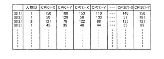
サンプル画像SIにおける特徴点CPの位置は、座標により特定される。図5は、サンプル画像SIに設定された特徴点CPの座標の一例を示す説明図である。図5において、SI(j)(j=1,2,3・・・)は各サンプル画像SIを示しており、CP(k)(k=0,1,・・・,67)は各特徴点CPを示している。また、CP(k)−Xは、特徴点CP(k)のX座標を示しており、CP(k)−Yは、特徴点CP(k)のY座標を示している。特徴点CPの座標としては、顔の大きさと顔の傾き(画像面内の傾き)と顔のX方向およびY方向の位置とのそれぞれについて正規化されたサンプル画像SIにおける所定の基準点(例えば画像の左下の点)を原点とした座標が用いられる。また、本実施例では、1つのサンプル画像SIに複数の人物の顔画像が含まれる場合が許容されており(例えばサンプル画像SI(2)には2人の顔画像が含まれている)、1つのサンプル画像SIにおける各人物は人物IDによって特定される。 The position of the feature point CP in the sample image SI is specified by coordinates. FIG. 5 is an explanatory diagram showing an example of the coordinates of the feature point CP set in the sample image SI. In FIG. 5, SI (j) (j = 1, 2, 3,...) Indicates each sample image SI, and CP (k) (k = 0, 1,..., 67) indicates each feature. Point CP is shown. CP (k) -X represents the X coordinate of the feature point CP (k), and CP (k) -Y represents the Y coordinate of the feature point CP (k). The coordinates of the feature point CP include predetermined reference points (for example, in the sample image SI normalized with respect to the size of the face, the inclination of the face (inclination in the image plane), and the position of the face in the X direction and the Y direction) The coordinates with the origin at the lower left point of the image are used. Further, in the present embodiment, a case where a plurality of human face images are included in one sample image SI is allowed (for example, two sample face images are included in the sample image SI (2)). Each person in one sample image SI is specified by a person ID.
つづいて、ユーザは、AAMの形状モデルの設定をおこなう(ステップS130)。具体的には、各サンプル画像SIにおける68個の特徴点CPの座標(X座標およびY座標)により構成される座標ベクトル(図5参照)に対する主成分分析をおこない、特徴点CPの位置により特定される顔の形状sが下記の式(1)によりモデル化する。なお、形状モデルは、特徴点CPの配置モデルとも呼ぶ。 Subsequently, the user sets an AAM shape model (step S130). Specifically, a principal component analysis is performed on a coordinate vector (see FIG. 5) composed of the coordinates (X coordinate and Y coordinate) of 68 feature points CP in each sample image SI, and specified by the position of the feature point CP. The face shape s to be modeled is expressed by the following equation (1). The shape model is also referred to as a feature point CP arrangement model.

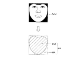
上記式(1)において、s0は平均形状である。図6は、平均形状s0の一例を示す説明図である。図6(a)および(b)に示すように、平均形状s0は、サンプル画像SIの各特徴点CPについての平均位置(平均座標)により特定される平均的な顔の形状を表すモデルである。なお、本実施例では、平均形状s0において、外周に位置する特徴点CP(フェイスラインおよび眉毛、眉間に対応する特徴点CP、図4参照)を結ぶ直線により囲まれた領域(図6(b)においてハッチングを付して示す)を「平均形状領域BSA」と呼ぶ。平均形状s0においては、図6(a)に示すように、特徴点CPを頂点とする複数の三角形領域TAが、平均形状領域BSAをメッシュ状に分割するように設定される。 In the above formula (1), s 0 is an average shape. FIG. 6 is an explanatory diagram showing an example of the average shape s 0 . As shown in FIGS. 6A and 6B, the average shape s 0 is a model representing the average face shape specified by the average position (average coordinate) for each feature point CP of the sample image SI. is there. In the present embodiment, in the average shape s 0 , a region surrounded by a straight line connecting feature points CP (face lines, eyebrows, feature points CP corresponding to the eyebrows, see FIG. 4) located on the outer periphery (FIG. 6 ( b) is indicated by hatching) and is referred to as “average shape region BSA”. In the average shape s 0 , as shown in FIG. 6A, a plurality of triangular areas TA having the feature points CP as vertices are set so as to divide the average shape area BSA into a mesh shape.
形状モデルを表す上記式(1)において、siは形状ベクトルであり、piは形状ベクトルsiの重みを表す形状パラメーターである。形状ベクトルsiは、顔の形状sの特性を表すベクトルであり、主成分分析により得られる第i主成分に対応する固有ベクトルである。上記式(1)に示すように、本実施例における形状モデルでは、特徴点CPの配置を表す顔形状sが、平均形状s0とn個の形状ベクトルsiの線形結合との和としてモデル化される。形状モデルにおいて形状パラメーターpiを適切に設定することにより、あらゆる画像における顔の形状sを再現することが可能である。 In the above equation (1) representing the shape model, s i is a shape vector, and p i is a shape parameter representing the weight of the shape vector s i . The shape vector s i is a vector representing the characteristics of the face shape s and is an eigenvector corresponding to the i-th principal component obtained by principal component analysis. As shown in the above equation (1), in the shape model in the present embodiment, the face shape s representing the arrangement of the feature points CP is modeled as the sum of the average shape s 0 and the linear combination of the n shape vectors s i. It becomes. By appropriately setting the shape parameter p i in the shape model, the face shape s in any image can be reproduced.
図7は、形状ベクトルsiおよび形状パラメーターpiと、顔の形状sとの関係を例示した説明図である。図7(a)に示すように、顔の形状sを特定するために、寄与率のより大きい主成分に対応する固有ベクトルから順に、累積寄与率に基づき設定された個数n(図7ではn=4)の固有ベクトルが、形状ベクトルsiとして採用される。形状ベクトルsiのそれぞれは、図7(a)の矢印に示すように、各特徴点CPの移動方向・移動量と対応している。本実施例では、最も寄与率の大きい第1主成分に対応する第1形状ベクトルs1は顔の左右振りにほぼ相関するベクトルとなっており、形状パラメーターp1を大小することにより、図7(b)に示すように、顔の形状sの横方向の顔向きが変化する。2番目に寄与率の大きい第2主成分に対応する第2形状ベクトルs2は顔の上下振りにほぼ相関するベクトルとなっており、形状パラメーターp2を大小することにより、図7(c)に示すように、顔の形状sの縦方向の顔向きが変化する。また、3番目に寄与率の大きい第3主成分に対応する第3形状ベクトルs3は顔の形状の縦横比にほぼ相関するベクトルとなっており、4番目に寄与率の大きい第4主成分に対応する第4形状ベクトルs4は口の開きの程度にほぼ相関するベクトルとなっている。このように、形状パラメーターの値は、顔の表情や、顔向きなど顔画像の特徴を表す。 FIG. 7 is an explanatory diagram illustrating the relationship between the shape vector s i, the shape parameter p i, and the face shape s. As shown in FIG. 7A, in order to specify the face shape s, the number n set based on the cumulative contribution rate in order from the eigenvector corresponding to the principal component having the larger contribution rate (in FIG. 7, n = The eigenvector of 4) is adopted as the shape vector s i . Each of the shape vectors s i corresponds to the movement direction / movement amount of each feature point CP, as indicated by the arrows in FIG. In this embodiment, most first shape vector s 1 corresponding to the first principal component having a large contribution rate is a vector that is approximately correlated with the left and right appearance of a face, by the magnitude of the shape parameter p 1, 7 As shown in (b), the horizontal face direction of the face shape s changes. Second shape vector s 2 corresponding to the large second principal component of the contribution rate to the second is a vector that is approximately correlated with the vertical appearance of a face, by the magnitude of the shape parameter p 2, FIG. 7 (c) As shown in FIG. 4, the vertical face direction of the face shape s changes. The third shape vector s 3 corresponding to the third principal component having the third largest contribution ratio is a vector that is substantially correlated with the aspect ratio of the face shape, and the fourth principal component having the fourth largest contribution ratio. The fourth shape vector s 4 corresponding to is a vector that is substantially correlated with the degree of mouth opening. As described above, the value of the shape parameter represents the feature of the face image such as facial expression and face orientation.
なお、形状モデル設定ステップ(ステップS130)において設定された平均形状s0および形状ベクトルsiは、AAM情報AMI(図1)として内部メモリー120に格納される。
The average shape s 0 and shape vector s i set in the shape model setting step (step S130) are stored in the
つづいて、AAMのテクスチャーモデルの設定をおこなう(ステップS140)。具体的には、まず、各サンプル画像SIに対して、サンプル画像SIにおける特徴点CPの設定位置が平均形状s0における特徴点CPの設定位置と等しくなるように、画像変換(以下、「ワープW」とも呼ぶ)を行う。 Subsequently, an AAM texture model is set (step S140). Specifically, first, for each sample image SI, image conversion (hereinafter referred to as “warp”) is performed so that the setting position of the feature point CP in the sample image SI is equal to the setting position of the feature point CP in the average shape s 0 . W ”).
図8は、サンプル画像SIのワープWの方法の一例を示す説明図である。各サンプル画像SIにおいては、平均形状s0と同様に、外周に位置する特徴点CPにより囲まれた領域をメッシュ状に分割する複数の三角形領域TAが設定される。ワープWは、複数の三角形領域TAのそれぞれについてのアフィン変換の集合である。すなわち、ワープWにおいては、サンプル画像SIにおけるある三角形領域TAの画像は、平均形状s0における対応する三角形領域TAの画像へとアフィン変換される。ワープWにより、特徴点CPの設定位置が平均形状s0における特徴点CPの設定位置と等しいサンプル画像SI(以下「サンプル画像SIw」と表す)が生成される。 FIG. 8 is an explanatory diagram showing an example of a method of warping W of the sample image SI. In each sample image SI, similarly to the average shape s 0 , a plurality of triangular regions TA that divide the region surrounded by the feature points CP located on the outer periphery into mesh shapes are set. The warp W is a set of affine transformations for each of the plurality of triangular areas TA. That is, in the warp W, an image of a certain triangular area TA in the sample image SI is affine transformed into an image of the corresponding triangular area TA in the average shape s 0 . With the warp W, a sample image SI (hereinafter referred to as “sample image SIw”) in which the set position of the feature point CP is equal to the set position of the feature point CP in the average shape s 0 is generated.
なお、各サンプル画像SIwは、平均形状領域BSA(図8においてハッチングを付して示す)を内包する矩形枠を外周とし、平均形状領域BSA以外の領域(以下「マスク領域MA」とも呼ぶ)がマスクされた画像として生成される。平均形状領域BSAとマスク領域MAとを併せた画像領域を基準領域BAと呼ぶ。また、各サンプル画像SIwは、例えば56画素×56画素のサイズの画像として正規化される。 Each sample image SIw has a rectangular frame containing an average shape area BSA (shown with hatching in FIG. 8) as an outer periphery, and an area other than the average shape area BSA (hereinafter also referred to as “mask area MA”). Generated as a masked image. An image area in which the average shape area BSA and the mask area MA are combined is referred to as a reference area BA. Each sample image SIw is normalized as an image having a size of 56 pixels × 56 pixels, for example.
次に、各サンプル画像SIwの画素群xのそれぞれにおける輝度値により構成される輝度値ベクトルに対する主成分分析が行われ、顔のテクスチャー(「見え」とも呼ぶ)A(x)が下記の式(2)によりモデル化される。なお、画素群xは、平均形状領域BSAに位置する画素の集合である。 Next, a principal component analysis is performed on a luminance value vector composed of luminance values in each pixel group x of each sample image SIw, and a facial texture (also referred to as “appearance”) A (x) is expressed by the following formula ( 2). The pixel group x is a set of pixels located in the average shape area BSA.
上記式(2)において、A0(x)は平均顔画像である。図9は、平均顔画像A0(x)の一例を示す説明図である。平均顔画像A0(x)は、ワープWの後のサンプル画像SIw(図8参照)の平均の顔が表された画像である。すなわち、平均顔画像A0(x)は、サンプル画像SIwの平均形状領域BSA内の画素群xの画素値(輝度値)の平均をとることにより算出される画像である。従って、平均顔画像A0(x)は、平均的な顔の形状における平均的な顔のテクスチャー(見え)を表すモデルである。なお、平均顔画像A0(x)は、サンプル画像SIwと同様に、平均形状領域BSAとマスク領域MAとで構成され、例えば56画素×56画素のサイズの画像として算出される。 In the above equation (2), A 0 (x) is an average face image. FIG. 9 is an explanatory diagram showing an example of the average face image A 0 (x). The average face image A 0 (x) is an image representing the average face of the sample image SIw (see FIG. 8) after the warp W. That is, the average face image A 0 (x) is an image calculated by taking the average of the pixel values (luminance values) of the pixel group x in the average shape area BSA of the sample image SIw. Therefore, the average face image A 0 (x) is a model representing the average face texture (appearance) in the average face shape. Note that the average face image A 0 (x) is composed of the average shape area BSA and the mask area MA, similarly to the sample image SIw, and is calculated as an image having a size of 56 pixels × 56 pixels, for example.
テクスチャーモデルを表す上記式(2)において、Ai(x)はテクスチャーベクトルであり、λiはテクスチャーベクトルAi(x)の重みを表すテクスチャーパラメーターである。テクスチャーベクトルAi(x)は、顔のテクスチャーA(x)の特性を表すベクトルであり、具体的には、主成分分析により得られる第i主成分に対応する固有ベクトルである。すなわち、寄与率のより大きい主成分に対応する固有ベクトルから順に、累積寄与率に基づき設定された個数mの固有ベクトルが、テクスチャーベクトルAi(x)として採用される。本実施例では、最も寄与率の大きい第1主成分に対応する第1テクスチャーベクトルA1(x)は、顔色の変化(性別の差とも捉えられる)にほぼ相関するベクトルとなっている。 In the above equation (2) representing the texture model, A i (x) is a texture vector, and λ i is a texture parameter representing the weight of the texture vector A i (x). The texture vector A i (x) is a vector representing the characteristics of the facial texture A (x), and specifically, is an eigenvector corresponding to the i-th principal component obtained by principal component analysis. That is, the number m of eigenvectors set based on the cumulative contribution rate is adopted as the texture vector A i (x) in order from the eigenvector corresponding to the principal component having the larger contribution rate. In the present embodiment, the first texture vector A 1 (x) corresponding to the first principal component having the largest contribution rate is a vector that is substantially correlated with a change in face color (also regarded as a gender difference).
上記式(2)に示すように、本実施例におけるテクスチャーモデルでは、顔の見えを表す顔のテクスチャーA(x)が、平均顔画像A0(x)とm個のテクスチャーベクトルAi(x)の線形結合との和としてモデル化される。テクスチャーモデルにおいてテクスチャーパラメーターλiを適切に設定することにより、あらゆる画像における顔のテクスチャーA(x)を再現することが可能である。なお、テクスチャーモデル設定ステップ(図2のステップS140)において設定された平均顔画像A0(x)およびテクスチャーベクトルAi(x)は、AAM情報AMI(図1)として内部メモリー120に格納される。
As shown in the above equation (2), in the texture model in the present embodiment, the facial texture A (x) representing the appearance of the face is the average face image A 0 (x) and m texture vectors A i (x ) And the linear combination. By appropriately setting the texture parameter λ i in the texture model, it is possible to reproduce the facial texture A (x) in any image. Note that the average face image A 0 (x) and the texture vector A i (x) set in the texture model setting step (step S140 in FIG. 2) are stored in the
以上説明したAAM設定処理(図2)により、顔の形状をモデル化する形状モデルと、顔のテクスチャーをモデル化するテクスチャーモデルが設定される。設定された形状モデルとテクスチャーモデルとを組み合わせることにより、すなわち合成されたテクスチャーA(x)に対して平均形状s0から形状sへの変換(図8に示したワープWの逆変換)を行うことにより、あらゆる顔画像の形状およびテクスチャーを再現することが可能である。 By the AAM setting process described above (FIG. 2), a shape model for modeling the face shape and a texture model for modeling the face texture are set. By combining the set shape model and the texture model, that is, the synthesized texture A (x) is converted from the average shape s 0 to the shape s (inverse conversion of the warp W shown in FIG. 8). Thus, it is possible to reproduce the shape and texture of any face image.
A3.顔特徴位置検出処理:
図10は、第1実施例における顔特徴位置検出処理の流れを示すフローチャートである。本実施例における顔特徴位置検出処理は、AAMを利用して、注目画像に含まれる顔画像における特徴点CPの配置を決定することにより、顔画像における特徴部位の位置を検出する処理である。上述したように、本実施例では、AAM設定処理(図2)において、人物の顔の器官(眉毛、目、鼻、口)および顔の輪郭における計68箇所の所定位置が、特徴部位として設定されている(図4参照)。そのため、本実施例の顔特徴位置検出処理では、人物の顔の器官および顔の輪郭における所定位置を表す68個の特徴点CPの位置を特定することで特徴部位の位置の検出をおこなう。
A3. Face feature position detection processing:
FIG. 10 is a flowchart showing the flow of face feature position detection processing in the first embodiment. The face feature position detection process in the present embodiment is a process for detecting the position of the feature part in the face image by determining the arrangement of the feature points CP in the face image included in the target image using AAM. As described above, in the present embodiment, in the AAM setting process (FIG. 2), a total of 68 predetermined positions in the human facial organs (eyebrows, eyes, nose, mouth) and facial contour are set as the characteristic parts. (See FIG. 4). Therefore, in the face feature position detection process of the present embodiment, the positions of the feature parts are detected by specifying the positions of 68 feature points CP representing predetermined positions in the organ and face contour of the person.
なお、顔特徴位置検出処理によって顔画像における特徴点CPの配置が決定されると、顔画像についての形状パラメーターpiや、テクスチャーパラメーターλiの値が特定される。従って、顔特徴位置検出処理の処理結果は、特定の表情(例えば笑顔や目を閉じた顔)の顔画像を検出するための表情判定や、特定の向き(例えば右向きや下向き)の顔画像を検出するための顔向き判定、顔の形状を変形する顔変形、顔の陰影補正等に利用可能である。 Note that when the arrangement of the feature points CP in the face image is determined by the face feature position detection process, the shape parameter p i and the value of the texture parameter λ i for the face image are specified. Therefore, the processing result of the face feature position detection process is a facial expression determination for detecting a facial image of a specific facial expression (for example, a smile or a face with closed eyes), or a facial image in a specific direction (for example, rightward or downward). It can be used for face orientation determination for detection, face deformation for deforming the face shape, face shadow correction, and the like.
はじめに、画像処理部200(図1)は、顔特徴位置検出処理の対象となる注目画像を表す画像データを取得する(ステップS210)。本実施例のプリンター100では、カードスロット172にメモリーカードMCが挿入されると、メモリーカードMCに格納された画像ファイルのサムネイル画像が表示部150に表示される。処理の対象となる1つまたは複数の画像は、操作部140を介してユーザにより選択される。画像処理部200は、選択された1つまたは複数の画像に対応する画像データを含む画像ファイルをメモリーカードMCより取得して内部メモリー120の所定の領域に格納する。なお、取得された画像データを注目画像データと呼び、注目画像データにより表される画像を注目画像OIと呼ぶものとする。
First, the image processing unit 200 (FIG. 1) acquires image data representing an attention image that is a target of face feature position detection processing (step S210). In the
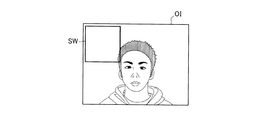
顔領域検出部210(図1)は、注目画像OIに含まれる顔画像の少なくとも一部を含む画像領域を顔領域FAとして検出する(ステップS220)。図11は、顔領域FAの検出処理の流れを示すフローチャートである。図12は、注目画像OIにおける顔領域FAの検出を説明するための説明図である。図12に示すように、顔領域検出部210は、予め規定された種々のサイズの正方形形状を有する複数のウィンドウSWのうちの1つを注目画像OIに設定する(ステップS300)。具体的には、顔領域検出部210は、まず、初期値として設定されているサイズのウィンドウSWを、初期位置として設定されている注目画像OI上の位置に設定する。
The face area detector 210 (FIG. 1) detects an image area including at least a part of the face image included in the target image OI as the face area FA (step S220). FIG. 11 is a flowchart showing a flow of processing for detecting the face area FA. FIG. 12 is an explanatory diagram for explaining the detection of the face area FA in the target image OI. As shown in FIG. 12, the face
顔領域検出部210は、ウィンドウSWにより規定される画像領域から顔判定に用いるための評価値Tvを算出する(ステップS310)。ここで、顔判定とは、ウィンドウSWにより規定される画像領域が顔の画像に対応する顔領域であるか否かの判定をいう。なお、本実施例では、顔判定は予め設定された特定顔傾き毎に実行される。すなわち、特定顔傾き毎に、ウィンドウSWにより規定される画像領域が当該特定顔傾き分だけ傾いた顔の画像に対応する画像領域であるか否かの判定が行われる。そのため、評価値Tvも特定顔傾き毎に算出される。ここで、特定顔傾きとは、後述する図16の下段に示すように、画像面内(インプレーン)における顔の画像の回転角度を意味している。本実施例では、特定顔傾きとして、画像の上下方向に沿って顔の画像が位置している状態(頭が上方向を向き顎が下方向を向いた状態)を基準(特定顔傾き=0度)とし、顔の画像の傾きを時計回りに30度ずつ増加させた計12個の傾き(0度、30度、60度、・・・、330度)が設定されている。 The face area detecting unit 2110 calculates an evaluation value Tv to be used for face determination from the image area defined by the window SW (step S310). Here, the face determination means determination whether or not the image area defined by the window SW is a face area corresponding to the face image. In the present embodiment, face determination is executed for each specific face inclination set in advance. That is, for each specific face inclination, it is determined whether or not the image area defined by the window SW is an image area corresponding to a face image inclined by the specific face inclination. Therefore, the evaluation value Tv is also calculated for each specific face inclination. Here, the specific face inclination means the rotation angle of the face image in the image plane (in-plane) as shown in the lower part of FIG. In this embodiment, the specific face inclination is based on the state where the face image is positioned along the vertical direction of the image (the state where the head faces upward and the jaw faces downward) (specific face inclination = 0). 12 degrees (0 degrees, 30 degrees, 60 degrees,..., 330 degrees) are set by increasing the inclination of the face image by 30 degrees clockwise.
評価値Tvの算出方法については特に限定はないが、本実施例では、評価値Tvの算出にN個のフィルタ(フィルタ1〜フィルタN)が用いられる。図13は、評価値Tvの算出に用いられるフィルタを説明するための説明図である。各フィルタ(フィルタ1〜フィルタN)の外形はウィンドウSWと同じアスペクト比を有しており(すなわち正方形形状であり)、各フィルタにはプラス領域paとマイナス領域maとが設定されている。顔領域検出部210は、ウィンドウSWにより規定される画像領域にフィルタX(X=1,2,・・・,N)を順に適用し、それぞれから評価値Tvの基礎となる基礎評価値vX(v1.v2.・・・,vN)を算出する。具体的には、基礎評価値vXは、フィルタXのプラス領域paに対応する画像領域に含まれる画素の輝度値の合計から、マイナス領域maに対応する画像領域に含まれる画素の輝度値の合計を差し引いた値である。
The calculation method of the evaluation value Tv is not particularly limited, but in this embodiment, N filters (
顔領域検出部210は、算出した基礎評価値vXと、各基礎評価値vX(v1.v2.・・・,vN)に対応して設定された閾値thX(th1,th2,・・・,thN)とをそれぞれ比較する。本実施例では、顔領域検出部210は、基礎評価値vXが閾値thX以上となるフィルタXでは、ウィンドウSWにより規定される画像領域が顔の画像に対応する画像領域であると判定し、フィルタXの出力値として値「1」を設定する。一方、基礎評価値vXが閾値thXより小さいフィルタXでは、ウィンドウSWにより規定される画像領域が顔の画像に対応するとは考えられない画像領域であると判定し、フィルタXの出力値として値「0」を設定する。各フィルタXには重み係数WeX(We1,We2,・・・,WeN)が設定されており、すべてのフィルタXについての出力値と重み係数WeXとの積の合計を評価値Tvとする。なお、顔判定に用いられるフィルタXの態様や閾値thX、重み係数WeX、後述の閾値THは、上記12個の特定顔傾きのそれぞれについて予め設定されており、顔学習データFLD(図1)として内部メモリー120に格納されている。
The face
顔領域検出部210は、算出された評価値Tvと閾値THとを比較する(ステップS320)。顔領域検出部210は、ある特定顔傾きについて評価値Tvが閾値TH以上である場合には(ステップS320:YES)、ウィンドウSWにより規定される画像領域は当該特定顔傾き分だけ傾いた顔の画像に対応する画像領域であるとして、ウィンドウSWにより規定される画像領域の位置、すなわち現在設定されているウィンドウSWの座標と、当該特定顔傾きと、を記憶する(ステップS330)。一方、いずれの特定顔傾きについても評価値Tvが閾値THより小さい場合には、ステップS330の処理はスキップされる。
The face
図14は、ウィンドウSWを移動させた状態を例示した説明図である。顔領域検出部210は、現在設定しているサイズのウィンドウSWにより注目画像OI全体をスキャンしたか否かを判定する(ステップS340)。まだ注目画像OIの全体をスキャンしていない場合は(ステップS340:NO)、図14に示すように、ウィンドウSWを所定の方向に所定の移動量だけ移動させる(ステップS350)。本実施例では、顔領域検出部210は、ウィンドウSWがウィンドウSWの水平方向の大きさの2割分の移動量で右方向に移動させるものとしている。また、ウィンドウSWをさらに右方向に移動させることができない位置に配置した場合には、ウィンドウSWを注目画像OIの左端まで戻すと共に、ウィンドウSWの垂直方向の大きさの2割分の移動量で下方向に移動させるものとしている。ウィンドウSWをさらに下方向に移動させることができない位置に配置した場合には、注目画像OIの全体をスキャンしたことになる。顔領域検出部210は、ウィンドウSWを移動させた後には、移動後のウィンドウSWについて、上述のステップS310以降の処理を実行する。
FIG. 14 is an explanatory diagram illustrating a state in which the window SW is moved. The face
顔領域検出部210は、現在設定しているサイズのウィンドウSWにより注目画像OIの全体をスキャンしたと判定すると(ステップS340:YES)、設定(用意)されたすべてのサイズのウィンドウSWにより注目画像OIをスキャンしたか否かを判定する(ステップS360)。顔領域検出部210は、使用していないウィンドウSWのサイズがある場合には(ステップS360:NO)、スキャンに用いるウィンドウSWのサイズを現在設定されているサイズの次に小さいサイズに変更する(ステップS370)。すなわち、本実施例では、顔領域検出部210は、最初に最大サイズのウィンドウSWによりスキャンをおこない、その後、順に小さいサイズのウィンドウSWを使用する。顔領域検出部210は、ウィンドウSWのサイズを変更した後には、変更後のサイズのウィンドウSWについて、上述のステップS300以降の処理を実行する。
If the face
顔領域検出部210は、すべてのサイズのウィンドウSWによりスキャンを実施すると(ステップS360:YES)、顔領域設定処理を実行する(ステップS380)。顔領域検出部210は、評価値Tvが閾値TH以上であると判定して記憶したウィンドウSWの座標と特定顔傾きとに基づき、顔の画像に対応する画像領域としての顔領域FAを設定する。具体的には、特定顔傾きが0度である場合には、ウィンドウSWにより規定される画像領域が、そのまま顔領域FAとして設定される。一方、特定顔傾きが0度以外である場合には、ウィンドウSWにより規定される画像領域を所定の点(例えばウィンドウSWの重心)を中心として時計回りに特定顔傾き分だけ回転させた画像領域が顔領域FAとして設定される。
When the face area detection unit 2110 performs the scan using the windows SW of all sizes (step S360: YES), the face area detection unit 2110 executes a face area setting process (step S380). The face
顔領域検出部210は、ウィンドウSWにより規定される画像領域が顔の画像に対応する画像領域であると判定したウィンドウSWが複数存在する場合には、各ウィンドウSWにおける所定の点(例えばウィンドウSWの重心)の座標の平均の座標を重心とし、各ウィンドウSWのサイズの平均のサイズを有する1つの新たなウィンドウを顔領域FAとして検出する。図15は、顔の画像に対応する画像領域であると判定された複数のウィンドウSWを例示した説明図である。図15(a)に示すように、例えば、互いに一部が重複する4つのウィンドウSW(SW1〜SW4)により規定される画像領域が顔画像に対応する画像領域であると判定した場合には、図15(b)に示すように、4つのウィンドウSWのそれぞれの重心の座標の平均の座標を重心とし、4つのウィンドウSWのそれぞれのサイズの平均のサイズを有する1つのウィンドウを顔領域FAとして設定する。
When there are a plurality of window SWs determined that the image area defined by the window SW is an image area corresponding to the face image, the face
顔領域FAを設定した後、顔領域検出部210は、顔領域信頼度を算出する(ステップS390)。顔領域信頼度は、顔領域FAの検出過程に基づき算出される指標であって、検出された顔領域FAが真に顔の画像に対応する画像領域であることの確からしさを表す指標である。顔領域FAの検出処理では、顔の画像に対応しない画像領域、すなわち、顔の画像をまったく含まない画像領域や顔の画像の一部を含むが、顔の画像に真に対応する画像領域ではない画像領域が、誤って顔領域FAとして検出される可能性がある。顔領域信頼度は、顔領域FAの検出が、誤検出ではなく正しい検出であることの確からしさを表している。
After setting the face area FA, the face
本実施例では、重複ウィンドウ数を最大重複ウィンドウ数で除した値を顔領域信頼度として用いている。ここで、重複ウィンドウ数は、顔領域FAを設定する際に参照したウィンドウSWの数、すなわち、ウィンドウSWにより規定される画像領域が顔の画像に対応する画像領域であると判定されたウィンドウSWの数である。例えば、図15(b)に示した顔領域FAの設定の際には、図15(a)に示した4つのウィンドウSW(SW1〜SW4)が参照されているため、重複ウィンドウ数は4となる。また、最大重複ウィンドウ数は、顔領域FAの検出の際に、注目画像OI上に配置されたすべてのウィンドウSWの内、少なくとも一部が顔領域FAに重複するウィンドウSWの数である。最大重複ウィンドウ数は、ウィンドウSWの移動ピッチやサイズ変更のピッチにより一義的に定まる。重複ウィンドウ数と最大重複ウィンドウ数はいずれも顔領域FAの検出過程において算出することができる。 In this embodiment, a value obtained by dividing the number of overlapping windows by the maximum number of overlapping windows is used as the face area reliability. Here, the number of overlapping windows is the number of windows SW referred to when setting the face area FA, that is, the window SW determined that the image area defined by the window SW is an image area corresponding to the face image. Is the number of For example, when the face area FA shown in FIG. 15B is set, the four windows SW (SW1 to SW4) shown in FIG. Become. The maximum number of overlapping windows is the number of windows SW that overlap at least a part of the face area FA among all the windows SW arranged on the target image OI when the face area FA is detected. The maximum number of overlapping windows is uniquely determined by the movement pitch of the window SW and the size change pitch. Both the number of overlapping windows and the maximum number of overlapping windows can be calculated in the process of detecting the face area FA.
検出された顔領域FAが真に顔の画像に対応する画像領域である場合には、位置およびサイズが互いに近似する複数のウィンドウSWについて、ウィンドウSWにより規定される画像領域が顔の画像に対応する顔領域であると判定される可能性が高い。一方、検出された顔領域FAが顔の画像に対応する画像領域ではなく誤検出である場合には、あるウィンドウSWについてはウィンドウSWにより規定される画像領域が顔の画像に対応する顔領域であると判定されたとしても、当該ウィンドウSWに位置およびサイズが近似する別のウィンドウSWについてはウィンドウSWにより規定される画像領域が顔の画像に対応する顔領域ではないと判定される可能性が高い。そのため、本実施例では、重複ウィンドウ数を最大重複ウィンドウ数で除した値を顔領域信頼度として用いている。上記により顔領域FAの検出処理は終了する。 If the detected face area FA is an image area that truly corresponds to a face image, the image area defined by the window SW corresponds to the face image for a plurality of windows SW whose positions and sizes approximate each other. There is a high possibility that the face area is determined to be a face area. On the other hand, when the detected face area FA is not an image area corresponding to a face image but a false detection, for a certain window SW, the image area defined by the window SW is a face area corresponding to the face image. Even if it is determined that there is another window SW whose position and size approximate that window SW, there is a possibility that the image area defined by the window SW is not determined to be a face area corresponding to the face image. high. Therefore, in this embodiment, a value obtained by dividing the number of overlapping windows by the maximum number of overlapping windows is used as the face area reliability. The face area FA detection process is thus completed.
ここで、顔判定に用いられるフィルタXの態様や閾値thX、重み係数WeX、後述の閾値THを含む顔学習データFLDについて説明する。顔学習データFLDは、サンプル画像を用いた学習によって設定される。図16は、学習に用いられるサンプル画像の一例を示す説明図である。学習には、顔の画像に対応した画像であることが予めわかっている複数の顔サンプル画像によって構成された顔サンプル画像群と、顔の画像に対応した画像ではないことが予めわかっている複数の非顔サンプル画像によって構成された非顔サンプル画像群と、が用いられる。学習による顔学習データFLDの設定は特定顔傾き毎に実行されるため、図16に示すように、顔サンプル画像群は、12個の特定顔傾きのそれぞれに対応したものが準備される。各特定顔傾きに対応した顔サンプル画像群は、画像サイズに対する顔の画像の大きさの比が所定の値の範囲内であると共に顔の画像の傾きが特定顔傾きに等しい複数の基本顔サンプル画像と、基本顔サンプル画像を例えば1.2倍から0.8倍までの範囲の所定の倍率で拡大および縮小した画像(例えば図16における画像FIaおよびFIb)や、基本顔サンプル画像を時計回りおよび反時計回りに例えば15度の範囲で所定の角度だけ回転させた画像(例えば図16における画像FIcおよびFId)を含む。サンプル画像を用いた学習は、例えばニューラルネットワークを用いた方法や、ブースティング(例えばアダブースティング)を用いた方法、サポートベクターマシーンを用いた方法等により実行される。例えば学習がニューラルネットワークを用いた方法により実行される場合には、各フィルタX(フィルタ1〜フィルタN)について、ある特定顔傾きに対応した顔サンプル画像群と非顔サンプル画像群とに含まれるすべてのサンプル画像を用いて基礎評価値vX(v1〜vN)が算出され、所定の顔検出率を達成する閾値thX(th1〜thN)が設定される。また、各フィルタXに設定された重み係数WeX(We1〜WeN)の初期値が設定され、顔サンプル画像群および非顔サンプル画像群の中から選択された1つのサンプル画像についての評価値Tvが算出される。学習においては、算出された評価値Tvにより、後述する顔判定をおこなった場合の結果の正誤に基づき、各フィルタXに設定された重み係数WeXの値が修正される。上記処理が特定顔傾き毎に実行されることにより、特定顔傾き毎の顔学習データFLDが設定される。 Here, the aspect of the filter X used for face determination, the threshold value thX, the weighting coefficient WeX, and face learning data FLD including a threshold value TH described later will be described. The face learning data FLD is set by learning using a sample image. FIG. 16 is an explanatory diagram illustrating an example of a sample image used for learning. For learning, a face sample image group composed of a plurality of face sample images that are known in advance to be images corresponding to face images, and a plurality of information that is known in advance to be images that do not correspond to face images. A non-face sample image group composed of non-face sample images. Since the setting of the face learning data FLD by learning is executed for each specific face inclination, as shown in FIG. 16, a face sample image group corresponding to each of 12 specific face inclinations is prepared. The face sample image group corresponding to each specific face inclination includes a plurality of basic face samples in which the ratio of the face image size to the image size is within a predetermined value range and the face image inclination is equal to the specific face inclination. An image and an image obtained by enlarging and reducing the basic face sample image at a predetermined magnification ranging from 1.2 times to 0.8 times (for example, images FIa and FIb in FIG. 16), and the basic face sample image clockwise And images rotated counterclockwise by a predetermined angle within a range of, for example, 15 degrees (for example, images FIc and FId in FIG. 16). Learning using a sample image is executed by, for example, a method using a neural network, a method using boosting (for example, adaboost), a method using a support vector machine, or the like. For example, when learning is performed by a method using a neural network, each filter X (filter 1 to filter N) is included in a face sample image group and a non-face sample image group corresponding to a specific face inclination. A basic evaluation value vX (v1 to vN) is calculated using all the sample images, and a threshold thX (th1 to thN) for achieving a predetermined face detection rate is set. Also, initial values of the weighting factors WeX (We1 to WeN) set for each filter X are set, and an evaluation value Tv for one sample image selected from the face sample image group and the non-face sample image group is set. Calculated. In learning, the value of the weighting coefficient WeX set for each filter X is corrected based on the correctness / incorrectness of the result when face determination described later is performed based on the calculated evaluation value Tv. By executing the above process for each specific face inclination, face learning data FLD for each specific face inclination is set.
顔領域FAの検出処理の後、初期位置設定部230(図1)は、注目画像OIに対する特徴点CPの初期位置を設定する(ステップS230)。図17は、第1実施例における特徴点CPの初期位置設定処理の流れを示すフローチャートである。はじめに、初期位置設定部230の取得部232は、顔領域検出情報を取得する(ステップS400)。顔領域検出情報とは、顔領域検出部210による顔領域FAの検出に関連する情報をいう。例えば、予め設定されている特定顔傾きの設定数(12個)、設定角度(0度、30度、60度、・・・、330度)、設定間隔(30度)や、顔領域FAの検出処理の統計的なデータに基づく顔領域FAにおける顔画像の位置の傾向などのほか、顔領域FAの検出処理において、顔領域検出部210が注目画像OIから顔領域FAを検出した際に特定される情報も含まれる。具体的には、検出した顔領域FAの特定顔傾きや、顔領域信頼度などである。本実施例では、顔領域検出情報として、特定顔傾きの設定間隔と、検出した顔領域FAの特定顔傾きと、顔領域信頼度を用いた例について説明する。取得部232は、顔領域FAの検出処理が実行されると、検出された顔領域FAについての特定顔傾きと、顔領域信頼度を取得する。
After the face area FA detection process, the initial position setting unit 230 (FIG. 1) sets the initial position of the feature point CP with respect to the target image OI (step S230). FIG. 17 is a flowchart showing the flow of the initial position setting process of the feature point CP in the first embodiment. First, the
初期位置候補設定部234は、顔領域検出情報に基づいて、特徴点CPを注目画像OI上の仮設定位置に設定する(ステップS410)。ここでは、特定顔傾きの設定間隔が30度、検出した顔領域FAの特定顔傾きが0度、顔領域信頼度が所定値以上である場合を例にして具体的に説明する。初期位置候補設定部234は、顔領域FAに対する顔画像の大きさ、傾き、位置(上下方向の位置および左右方向の位置)を表すグローバルパラメーターの値を種々変更することにより、特徴点CPを注目画像OI上に設定する。仮設定位置は、特許請求の範囲における「初期位置の候補」に該当する。
The initial position
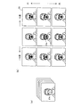
図18は、グローバルパラメーターの値を変更することによる特徴点CPの仮設定位置を例示した説明図である。図18(a)および図18(b)には、注目画像OIにおける特徴点CPと、特徴点CPをつないで形成されるメッシュが示されている。初期位置候補設定部234は、図18(a)および図18(b)の中央に示すように、顔領域FAの中央部に平均形状s0が形成されるような特徴点CPの仮設定位置(以下、「基準仮設定位置」とも呼ぶ)を設定する。
FIG. 18 is an explanatory view exemplifying a temporary setting position of the feature point CP by changing the value of the global parameter. 18A and 18B show a mesh formed by connecting feature points CP and feature points CP in the target image OI. The initial position
初期位置候補設定部234は、また、基準仮設定位置に対して、グローバルパラメーターの値を種々変更させた複数の仮設定位置を設定する。グローバルパラメーター(大きさ、傾き、上下方向の位置および左右方向の位置)を変更することは、注目画像OIにおいて特徴点CPにより形成されるメッシュが拡大・縮小、傾きを変更、並行移動することに相当する。従って、初期位置候補設定部234は、図18(a)に示すように、基準仮設定位置のメッシュを所定倍率で拡大または縮小したメッシュを形成するような仮設定位置(基準仮設定位置の図の下および上に示す)や、所定角度だけ時計回りまたは半時計回りに傾きを変更したメッシュを形成するような仮設定位置(基準仮設定位置の図の右および左に示す)を設定する。また、初期位置候補設定部234は、基準仮設定位置のメッシュに対して、拡大・縮小および傾きの変更を組み合わせた変換を行ったメッシュを形成するような仮設定位置(基準仮設定位置の図の左上、左下、右上、右下に示す)も設定する。
The initial position
また、図18(b)に示すように、初期位置候補設定部234は、基準仮設定位置のメッシュを所定量だけ上または下に並行移動したメッシュを形成するような仮設定位置(基準仮設定位置の図の上および下に示す)や、左または右に並行移動したメッシュを形成するような仮設定位置(基準仮設定位置の図の左および右に示す)を設定する。また、初期位置候補設定部234は、基準仮設定位置のメッシュに対して、上下および左右の並行移動を組み合わせた変換を行ったメッシュを形成するような仮設定位置(基準仮設定位置の図の左上、左下、右上、右下に示す)も設定する。
Further, as shown in FIG. 18B, the initial position
ここで、検出した顔領域FAの特定顔傾きが0度、特定顔傾きの設定間隔が30度である場合、メッシュの回転角度は、−15度から15度までの範囲に設定される。すなわち、初期位置候補設定部234は、特定顔傾きの設定角度(0度、30度、60度、・・・、330度)のうち、検出した顔領域FAの特定顔傾き(0度)と隣接する設定角度(−30度および30度)との一方の中間値(−15度)から他方の中間値(15度)までの範囲を、メッシュの回転角度の範囲として設定する。
Here, when the specific face inclination of the detected face area FA is 0 degree and the setting interval of the specific face inclination is 30 degrees, the rotation angle of the mesh is set in a range from −15 degrees to 15 degrees. That is, the initial position
図19は、顔領域FAの特定顔傾きが30度の場合における特徴点CPの仮設定位置を例示した説明図である。図19に示すように、検出した顔領域FAの特定顔傾きが30度、特定顔傾きの設定間隔が30度である場合、メッシュの回転角度は、15度から45度までの範囲に設定される。すなわち、初期位置候補設定部234は、特定顔傾きの設定角度(0度、30度、60度、・・・、330度)のうち、検出した顔領域FAの特定顔傾き(30度)と隣接する設定角度(0度および60度)との一方の中間値(15度)から他方の中間値(45度)までの範囲を、メッシュの回転角度の範囲として設定する。いいかえれば、初期位置候補設定部234は、予め設定されている特定傾きが0度の場合における仮設定位置に対して、検出された顔領域FAの特定傾きの角度分それぞれ傾けて設定する。
FIG. 19 is an explanatory diagram illustrating the temporarily set position of the feature point CP when the specific face inclination of the face area FA is 30 degrees. As shown in FIG. 19, when the specific face inclination of the detected face area FA is 30 degrees and the specific face inclination setting interval is 30 degrees, the mesh rotation angle is set in the range of 15 degrees to 45 degrees. The That is, the initial position
初期位置候補設定部234は、図18(a)に示す基準仮設定位置以外の8つの仮設定位置のそれぞれにおけるメッシュに対して図18(b)に示す上下左右の並行移動が実行される仮設定位置も設定する。従って、本実施例では、4つのグローバルパラメーター(大きさ、傾き、上下方向の位置、左右方向の位置)をそれぞれ既知の3段階の値として組み合わせにより設定される80通り(=3×3×3×3−1)の仮設定位置と、基準仮設定位置の合計81通りの仮設定位置が設定される。
The initial position
初期位置候補設定部234は、顔領域信頼度が閾値以上の場合、上述のとおり81通りの仮設定位置を設定するが、顔領域信頼度が閾値より小さい場合には、顔領域信頼度が閾値以上の場合より多くの仮設定位置を設定する。具体的には、上述では、メッシュの回転および拡大・縮小、メッシュの上下移動および左右移動、についてそれぞれ3段階に変化させて仮設定位置が設定されているが、初期位置候補設定部234は、顔領域信頼度と閾値との比較結果に基づいて、設定する仮設定位置のそれぞれの変化(回転、拡大・縮小、上下移動、左右移動)の段階数を決定する。図20は、仮設定位置の変化の段階数を説明するための説明図である。初期位置候補設定部234は、顔領域信頼度が閾値以上である場合には、図18に示すように、メッシュの回転および拡大・縮小、メッシュの上下移動および左右移動のそれぞれについて3段階に変化させて仮設定位置を設定する。一方、初期位置候補設定部234は、顔領域信頼度が閾値より小さい場合には、図20に一例を示すように、メッシュの回転および拡大・縮小、メッシュの上下移動および左右移動のそれぞれについて5段階に変化させて仮設定位置を設定する。
The initial position
メッシュを設定する範囲は、3段階の場合と5段階の場合で同一の範囲であってもよいし異なる範囲であってもよい。すなわち、図20に示すように、5段階の場合であっても図18に示す3段階の場合と同一の範囲(−15度〜15度)であり、メッシュの回転角度が−15度、0度、15度、の3段階であったものを、−15度、−7.5度、0度、7.5度、15度の5段階に細分化して設定してもよいし、メッシュの回転角度を−30度、−15度、0度、15度、30度の5段階として3段階の場合に比べ広い範囲に設定してもよい。また、メッシュの回転および拡大・縮小、メッシュの上下移動および左右移動のすべてを5段階に設定する必要はなく、一部を5段階とし、ほかを3段階として設定してもよい。 The range for setting the mesh may be the same range or a different range in the case of three stages and in the case of five stages. That is, as shown in FIG. 20, even in the case of 5 steps, the same range (−15 to 15 degrees) as in the case of 3 steps shown in FIG. 18, and the rotation angle of the mesh is −15 degrees, 0 Degrees, 15 degrees, and 3 levels may be subdivided into 5 levels of -15 degrees, -7.5 degrees, 0 degrees, 7.5 degrees, and 15 degrees. The rotation angle may be set to a wide range as compared with the case of three stages, with five stages of −30 degrees, −15 degrees, 0 degrees, 15 degrees, and 30 degrees. Further, it is not necessary to set all of the mesh rotation, enlargement / reduction, mesh up / down movement, and left / right movement in five stages, some of which may be set in five stages, and others may be set in three stages.
生成部236は、設定された各仮設定位置に対応する平均形状画像I(W(x;p))を生成する(ステップS420)。図21は、平均形状画像I(W(x;p))の一例を示す説明図である。平均形状画像I(W(x;p))は、入力画像における特徴点CPの配置が平均形状s0における特徴点CPの配置と等しくなるような変換によって算出される。
The
平均形状画像I(W(x;p))を算出するための変換は、AAM設定処理において、サンプル画像SIw算出のための変換と同様に、三角形領域TA毎のアフィン変換の集合であるワープWにより行われる。具体的には、注目画像OIに配置された特徴点CPによって、外周に位置する特徴点CP(フェイスラインおよび眉毛、眉間に対応する特徴点CP)を結ぶ直線により囲まれた領域である平均形状領域BSAが特定され、注目画像OIにおける平均形状領域BSAに対して三角形領域TA毎のアフィン変換が行われることにより、平均形状画像I(W(x;p))が算出される。本実施例では、平均形状画像I(W(x;p))は、平均顔画像A0(x)と同様に平均形状領域BSAおよびマスク領域MAにより構成され、平均顔画像A0(x)と同サイズの画像として算出される。 The transformation for calculating the average shape image I (W (x; p)) is a warp W that is a set of affine transformations for each triangular area TA in the AAM setting process, similarly to the transformation for calculating the sample image SIw. Is done. Specifically, an average shape that is an area surrounded by a straight line connecting feature points CP (feature points CP corresponding to face lines, eyebrows, and eyebrows) located on the outer periphery by feature points CP arranged in the target image OI The area BSA is specified, and the average shape image I (W (x; p)) is calculated by performing affine transformation for each triangular area TA on the average shape area BSA in the target image OI. In this embodiment, the average shape image I (W (x; p) ) is composed of an average face image A 0 (x) and an average shape area BSA and a mask area MA, average face image A 0 (x) And is calculated as an image of the same size.
ここで、平均形状s0における平均形状領域BSAに位置する画素の集合を画素群xと表す。また、ワープW実行後の画像(平均形状s0を有する顔画像)における画素群xに対応するワープW実行前の画像(注目画像OIの平均形状領域BSA)における画素群をW(x;p)と表す。平均形状画像は、注目画像OIの平均形状領域BSAにおける画素群W(x;p)のそれぞれにおける輝度値により構成される画像であるため、I(W(x;p))と表される。図21には、図18(a)に示した9個の仮設定位置に対応する9個の平均形状画像I(W(x;p))を示している。 Here, a set of pixels located in the average shape area BSA in the average shape s 0 is represented as a pixel group x. In addition, the pixel group in the image before the warp W execution (the average shape area BSA of the target image OI) corresponding to the pixel group x in the image after the warp W execution (face image having the average shape s 0 ) is represented by W (x; p ). Since the average shape image is an image composed of luminance values in each of the pixel groups W (x; p) in the average shape region BSA of the target image OI, it is represented as I (W (x; p)). FIG. 21 shows nine average shape images I (W (x; p)) corresponding to the nine temporarily set positions shown in FIG.
算出部238は、各仮設定位置に対応する平均形状画像I(W(x;p))と平均顔画像A0(x)との差分画像Ieを算出する(ステップS430)。差分画像Ieは、平均形状画像I(W(x;p))と平均顔画像A0(x)の各画素値の差であり、本実施例では差分値とも呼ぶ。差分画像Ieは、特徴点CPの設定位置が、特徴部位の位置と一致している場合には表れないため、特徴点CPの設定位置と、特徴部位の位置と差異を表している。本実施例では、特徴点CPの仮設定位置は81種類設定されているため、算出部238は、81個の差分画像Ieを算出することとなる。
The
初期位置設定部230は、各差分画像Ieの画素値からノルムを算出し、ノルムの値が最も小さい差分画像Ieに対応する仮設置位置(以下「ノルム最小仮設定位置」とも呼ぶ)を、注目画像OIにおける特徴点CPの初期位置として設定する(ステップS440)。本実施例において、ノルムを算出するための画素値は輝度値であってもよいしRGB値であってもよい。以上により特徴点CP初期位置設定処理が完了する。
The initial
特徴点CP初期位置設定処理が完了すると、特徴位置検出部220は、注目画像OIにおける特徴点CPの設定位置の補正を行う(ステップS240)。図22は、第1実施例における特徴点CP設定位置補正処理の流れを示すフローチャートである。
When the feature point CP initial position setting process is completed, the feature
特徴位置検出部220は、注目画像OIから平均形状画像I(W(x;p))を算出する(ステップS510)。平均形状画像I(W(x;p))の算出方法は、特徴点CP初期位置設定処理におけるステップS420と同様である。
The feature
特徴位置検出部220は、平均形状画像I(W(x;p))と平均顔画像A0(x)との差分画像Ieを算出する(ステップS520)。特徴位置検出部220は、差分画像Ieに基づき、特徴点CPの設定位置補正処理が収束したか否かを判定する(ステップS530)。特徴位置検出部220は、差分画像Ieのノルムを算出し、ノルムの値が予め設定された閾値より小さい場合には収束したと判定し、ノルムの値が閾値以上の場合には未だ収束していないと判定する。
The feature
なお、特徴位置検出部220は、算出された差分画像Ieのノルムの値が前回のステップS520において算出された値よりも小さい場合には収束したと判定し、前回値以上である場合には未だ収束していないと判定するものとしてもよい。あるいは、特徴位置検出部220は、閾値による判定と前回値との比較による判定とを組み合わせて収束判定を行うものとしてもよい。例えば、特徴位置検出部220は、算出されたノルムの値が、閾値より小さく、かつ、前回値より小さい場合にのみ収束したと判定し、それ以外の場合には未だ収束していないと判定するものとしてもよい。
The feature
上記のステップS530の収束判定において未だ収束していないと判定された場合には、補正部222は、パラメーター更新量ΔPを算出する(ステップS540)。パラメーター更新量ΔPは、4個のグローバルパラメーター(全体としての大きさ、傾き、X方向位置、Y方向位置)、および、AAM設定処理により算出されるn個の形状パラメーターpi(式(1)参照)の値の変更量を意味している。なお、特徴点CPを初期位置に設定した直後においては、グローバルパラメーターは、特徴点CP初期位置設定処理において決定された値が設定されている。また、このときの特徴点CPの初期位置と平均形状s0の特徴点CPの設定位置との相違は、全体としての大きさ、傾き、位置の相違に限られるため、形状モデルにおける形状パラメーターpiの値はすべてゼロである。
When it is determined in the convergence determination in step S530 that the convergence has not yet occurred, the
パラメーター更新量ΔPは、下記の式(3)により算出される。すなわち、パラメーター更新量ΔPは、アップデートマトリックスRと差分画像Ieとの積である。 The parameter update amount ΔP is calculated by the following equation (3). That is, the parameter update amount ΔP is a product of the update matrix R and the difference image Ie.
式(3)におけるアップデートマトリックスRは、差分画像Ieに基づきパラメーター更新量ΔPを算出するために予め学習により設定されたM行N列のマトリックスであり、AAM情報AMI(図1)として内部メモリー120に格納されている。本実施例では、アップデートマトリックスRの行数Mは、グローバルパラメーターの数(4個)と、形状パラメーターpiの数(n個)との和((4+n)個)に等しく、列数Nは、平均顔画像A0(x)の平均形状領域BSA内の画素数(56画素×56画素−マスク領域MAの画素数)に等しい。アップデートマトリックスRは、下記の式(4)および(5)により算出される。
The update matrix R in the expression (3) is a matrix of M rows and N columns set in advance by learning in order to calculate the parameter update amount ΔP based on the difference image Ie, and the
補正部222は、算出されたパラメーター更新量ΔPに基づきパラメーター(4個のグローバルパラメーターおよびn個の形状パラメーターpi)を更新する(ステップS550)。これにより、注目画像OIにおける特徴点CPの設定位置が更新される。補正部222は、差分画像Ieのノルムが小さくなるように更新する。パラメーターの更新の後には、再度、特徴点CPの設置位置が補正された注目画像OIからの平均形状画像I(W(x;p))の算出(ステップS510)、差分画像Ieの算出(ステップS520)、差分画像Ieに基づく収束判定(ステップS530)が行われる。再度の収束判定においても収束していないと判定された場合には、さらに、差分画像Ieに基づくパラメーター更新量ΔPの算出(ステップS540)、パラメーターの更新による特徴点CPの設定位置補正(ステップS550)が行われる。
The
図22のステップS510からS550までの処理が繰り返し実行されると、注目画像OIにおける各特徴部位に対応する特徴点CPの位置は実際の特徴部位の位置に全体として近づいていき、ある時点で収束判定(ステップS530)において収束したと判定される。収束判定において収束したと判定されると、顔特徴位置検出処理が完了する(ステップS560)。このとき設定されているグローバルパラメーターおよび形状パラメーターの値により特定される特徴点CPの設定位置が、最終的な注目画像OIにおける特徴点CPの設定位置として特定される。ステップS510からS550までの処理の繰り返しにより、注目画像OIにおける各特徴部位に対応する特徴点CPの位置と実際の特徴部位の位置とが一致する場合もある。 When the processing from step S510 to step S550 in FIG. 22 is repeatedly executed, the position of the feature point CP corresponding to each feature part in the target image OI approaches the position of the actual feature part as a whole, and converges at a certain time. In the determination (step S530), it is determined that convergence has occurred. If it is determined in the convergence determination that convergence has been achieved, the face feature position detection process is completed (step S560). The setting position of the feature point CP specified by the values of the global parameter and the shape parameter set at this time is specified as the setting position of the feature point CP in the final target image OI. By repeating the processing from step S510 to S550, the position of the feature point CP corresponding to each feature part in the target image OI may coincide with the position of the actual feature part.
図23は、顔特徴位置検出処理の結果の一例を示す説明図である。図23には、注目画像OIにおいて最終的に特定された特徴点CPの設定位置が示されている。特徴点CPの設定位置により、注目画像OIに含まれる顔の特徴部位(人物の顔の器官(眉毛、目、鼻、口)および顔の輪郭における所定位置)の位置が特定されるため、注目画像OIにおける人物の顔の器官の形状・位置や顔の輪郭形状の検出が可能となる。以上により、顔特徴位置検出処理が完了する。 FIG. 23 is an explanatory diagram illustrating an example of a result of the face feature position detection process. FIG. 23 shows the setting positions of the feature points CP finally specified in the target image OI. Since the position of the feature point CP specifies the position of the facial feature part (predetermined position in the facial organs (eyebrows, eyes, nose, mouth) and facial contour) included in the attention image OI. It is possible to detect the shape and position of the human face organ and the face contour shape in the image OI. Thus, the face feature position detection process is completed.
印刷処理部320は、顔の器官の形状・位置や顔の輪郭形状の検出がなされた注目画像OIについての印刷データを生成する。具体的には、印刷処理部320は、注目画像OIについて、各画素の画素値をプリンター100が用いるインクに合わせるための色変換処理や、色変換処理後の画素の階調をドットの分布によって表すためのハーフトーン処理や、ハーフトーン処理された画像データのデータ並びをプリンター100に転送すべき順序に並び替えるためのラスタライズ処理等を実施して印刷データを生成する。印刷機構160は、印刷処理部320により生成された印刷データに基づいて、顔の器官の形状・位置や顔の輪郭形状の検出がなされた注目画像OIの印刷をおこなう。なお、印刷処理部320は、注目画像OIについての印刷データに限らず、検出された顔の器官の形状・位置や顔の輪郭形状に基づいて、顔変形や、顔の陰影補正など所定の処理が施された画像の印刷データについても生成することができる。また、印刷機構160は、印刷処理部320により生成された印刷データに基づいて、顔変形や、顔の陰影補正などの処理が施された画像の印刷をおこなうこともできる。
The
以上説明したように、第1の実施例に係る画像処理装置によれば、特徴点CPの初期位置を、顔領域検出情報に基づいて設定される複数の初期位置の候補から設定するため、初期位置を特徴部位により近い位置に設定することができる。これにより、注目画像に含まれる顔の特徴部位の位置を検出する処理の効率化・高速化を図ることができる。すなわち、顔領域FAにおける顔画像の位置や範囲等は、つねに一定かつ顔領域FAの中心と顔画像の中心が一致するわけではなく、注目画像OIに含まれる顔画像の向きや鮮明さのほか、顔領域検出部210の検出特性などによって顔画像の位置や範囲が異なる。そのため、特徴点CPを初期位置の候補となる注目画像OI上の仮設定位置に設定する際に、顔領域検出部210による顔領域FAの検出に関連する情報を用いることで、特徴点CPを検出対象の特徴部位に対してより適当な位置に設定することができる。
As described above, according to the image processing apparatus of the first embodiment, the initial position of the feature point CP is set from a plurality of initial position candidates set based on the face area detection information. The position can be set closer to the characteristic part. Thereby, it is possible to increase the efficiency and speed of the process of detecting the position of the facial feature part included in the target image. That is, the position and range of the face image in the face area FA are not always constant, and the center of the face area FA does not always coincide with the center of the face image. In addition to the orientation and clarity of the face image included in the target image OI, The position and range of the face image vary depending on the detection characteristics of the face
具体的には、初期位置候補設定部234は、顔領域信頼度が低い場合、すなわち、顔領域信頼度が閾値より小さい場合には、顔領域FAに顔画像が含まれている可能性が低いことから、顔領域信頼度が高い場合に比べて、特徴点CPの仮設定位置の数を増やすことにより、特徴部位に対応した適当な位置に特徴点CPを配置できる可能性が高くすることができる。反対に、顔領域信頼度が高い場合には、顔領域FAに顔画像が含まれている可能性が高いため、顔領域信頼度が低い場合に比べて、特徴点CPの仮設定位置の数を減らすことにより効率的かつ高速に顔の特徴部位の位置の検出をおこなうことができる。
Specifically, the initial position
また、初期位置候補設定部234は、予め設定されている特定傾きが0度の場合における仮設定位置に対して、検出された顔領域FAの特定傾きの角度分それぞれ傾けて設定するため、特徴部位に対応したより適当な位置に特徴点CPを配置することができる。よって、注目画像に含まれる顔の特徴部位の位置を効率的かつ高速に検出することができる。
Further, the initial position
また、初期位置候補設定部234は、特定顔傾きの設定角度(例えば、0度、30度、60度、・・・、330度)のうち、検出した顔領域FAの特定顔傾き(例えば、0度)と隣接する設定角度(例えば、−30度および30度)との一方の中間値(例えば、−15度)から他方の中間値(例えば、15度)までの範囲を、メッシュの回転角度の範囲として設定するため、顔領域FAの検出処理の結果、実際の顔画像の顔の傾きが含まれている可能性の低い角度の範囲にメッシュを回転させて仮設定位置を設定する処理の無駄を抑制し、実際の顔画像の顔の傾きが含まれている可能性の高い範囲にメッシュを回転させて仮設置位置を設定することができる。よって、注目画像に含まれる顔の特徴部位の位置を効率的かつ高速に検出することができる。
In addition, the initial position
第1の実施例に係る画像処理装置によれば、特徴点CP初期位置設定処理において、グローバルパラメーターを用いて特徴点CPの初期位置を設定するため、注目画像に含まれる顔の特徴部位の位置を検出する処理の効率化・高速化を図ることができる。具体的には、4つのグローバルパラメーター(大きさ、傾き、上下方向の位置、左右方向の位置)の値をそれぞれ変更させて、種々のメッシュを形成する特徴点CPの仮設定位置を予め複数用意し、ノルムの値が最も小さい差分画像Ieに対応する仮設定位置を初期位置としている。これにより、注目画像OIにおける特徴点CPの初期位置を顔の特徴部位の位置のより近くに設定することができる。よって、特徴点CP設定位置補正処理において、補正部222による補正が容易となるため、顔の特徴部位の位置を検出する処理の効率化・高速化を図ることができる。
According to the image processing apparatus according to the first embodiment, in the feature point CP initial position setting process, the initial position of the feature point CP is set using a global parameter. It is possible to increase the efficiency and speed of the process for detecting the. Specifically, multiple global parameters (size, inclination, vertical position, horizontal position) are changed to prepare multiple temporary setting positions for feature points CP that form various meshes. The temporary setting position corresponding to the difference image Ie having the smallest norm value is set as the initial position. Thereby, the initial position of the feature point CP in the target image OI can be set closer to the position of the facial feature part. Accordingly, in the feature point CP setting position correction process, correction by the
第1の実施例に係るプリンター100によれば、顔の器官の形状・位置や顔の輪郭形状の検出がなされた注目画像OIについての印刷をおこなうことができる。これにより、特定の表情(例えば笑顔や目を閉じた顔)の顔画像を検出するための表情判定や、特定の向き(例えば右向きや下向き)の顔画像を検出するための顔向き判定をおこなった後に、判定結果に基づいて任意の画像を選択して印刷をおこなうことができる。また、検出された顔の器官の形状・位置や顔の輪郭形状に基づいて、顔変形や、顔の陰影補正など所定の処理が施された画像の印刷をおこなうことができる。これにより、特定の顔画像について、顔変形や、顔の陰影補正等をおこなった後に印刷をおこなうことができる。
According to the
B.第2実施例:
第1実施例では、取得部232は、顔領域検出情報を取得し(ステップS400)、初期位置候補設定部234は、取得部232が取得した顔領域検出情報に基づいて、特徴点CPを注目画像OI上の仮設定位置に設定していたが(ステップS410)、顔特徴位置検出処理の度に顔領域検出情報を取得する態様ではなく、初期位置候補設定部234は、予め顔領域検出情報に基づいて設定された仮設定位置に特徴点CPを設定してもよい。
B. Second embodiment:
In the first example, the
図24は、顔領域検出情報と特徴点CPの仮設定位置について第2の例を示した説明図である。図25は、顔領域検出情報と特徴点CPの仮設定位置についての第3の例を示した説明図である。第2実施例における初期位置候補設定部234は、特徴点CPの初期位置の設定に、顔領域FAにおける顔画像の位置の傾向に基づいて予め設定された特徴点CPの仮設定位置を用いる。具体的には、図24(a)に示すように、顔領域FAの検出処理の統計的なデータにより、顔領域FAに対して顔画像が下側に位置することが特定された場合には、図24(b)に示すように、顔領域FAに対してメッシュが下側に位置するように予めグローバルパラメーターが設定される。また、顔領域FAに対して顔画像が上側に位置する場合や、左右のいずれかに偏って位置する場合についても同様に予めグローバルパラメーターを設定することにより、顔画像のより近くにメッシュを配置することができる。グローバルパラメーターの設定は、ユーザによりおこなわれてもよいし、画像処理部200によりおこなわれてもよい。
FIG. 24 is an explanatory diagram showing a second example of the temporary setting positions of the face area detection information and the feature points CP. FIG. 25 is an explanatory diagram showing a third example of the temporary setting positions of the face area detection information and the feature points CP. The initial position
また、初期位置候補設定部234は、図25(a)に示すように、顔領域FAの検出処理の統計的なデータにより、顔領域FAが顔画像に対して小さいことが特定された場合には、図25(b)に示すように、顔領域FAに対してメッシュが大きくなるように予めグローバルパラメーターが設定される。また、顔領域FAが顔画像に対して大きい場合や、顔領域FAに対して顔画像が上下左右に偏って位置するとともに、顔領域FAが顔画像に対して大小する場合についても同様に予めグローバルパラメーターを設定することにより、顔画像のより近くにメッシュを配置することができる。
In addition, as illustrated in FIG. 25A, the initial position
第2の実施例に係る画像処理装置によれば、画像処理部200は、取得部232を備えていなくても、注目画像に含まれる顔の特徴部位の位置を検出する処理の効率化・高速化を図ることができる。具体的には、取得部232により、顔特徴位置検出処理の度に顔領域検出情報を取得しなくても、例えば、顔領域FAにおける顔画像の位置の傾向など、顔領域FAの検出処理により特定される情報以外の顔領域検出情報であれば、顔領域検出情報に基づいて特徴点CPの仮設定位置を予め設定することができる。これにより、特徴点CPを特徴部位に対してより適当な位置に設定することができる。また、初期位置候補設定部234は、取得部232が取得した顔領域検出情報に基づいて、特徴点CPを注目画像OI上の仮設定位置に設定する必要はなく、顔領域検出情報に基づいて予め設定された仮設定位置に特徴点CPを設定してもよい。
According to the image processing apparatus according to the second embodiment, the
C.変形例:
なお、この発明は上記の実施例や実施形態に限られるものではなく、その要旨を逸脱しない範囲において種々の態様において実施することが可能であり、例えば次のような変形も可能である。
C. Variation:
The present invention is not limited to the above-described examples and embodiments, and can be implemented in various modes without departing from the gist thereof. For example, the following modifications are possible.
C1.変形例1:
第1実施例では、初期位置候補設定部234は、顔領域信頼度が閾値以上である場合には、図18に示すように、メッシュの回転および拡大・縮小、メッシュの上下移動および左右移動のそれぞれについて3段階に変化させて仮設定位置を設定し、顔領域信頼度が閾値より小さい場合には、図20に一例を示すように、メッシュの回転および拡大・縮小、メッシュの上下移動および左右移動のそれぞれについて5段階に変化させて仮設定位置を設定するとして説明したが、上記の3段階および5段階は例示にすぎず、例えば4段階や6段階のようにこれ以外の段階数に設定されていてもよい。
C1. Modification 1:
In the first example, the initial position
C2.変形例2:
第1実施例では、顔領域検出情報として、特定顔傾きの設定数、設定角度、設定間隔や、顔領域FAの検出処理の統計的なデータに基づく顔領域FAにおける顔画像の位置の傾向、顔領域FAの検出処理において、顔領域検出部210が注目画像OIから顔領域FAを検出した際に特定される情報などを示したが、顔領域検出情報は、顔領域検出部210による顔領域FAの検出に関連する情報であれば上記に限定されず、これら以外の情報も含まれる。例えば、前回の顔領域FAの検出処理の結果なども含まれる。また、顔領域検出部210による顔領域FAの検出に関連する情報についても、検出した顔領域FAの特定顔傾きや、顔領域信頼度に限定されず、これら以外の情報も含まれる。例えば、ウィンドウSWの水平方向および垂直方向の移動量や、重複ウィンドウ数なども含まれる。
C2. Modification 2:
In the first embodiment, as the face area detection information, the number of specific face inclinations, the setting angle, the setting interval, and the tendency of the position of the face image in the face area FA based on statistical data of the face area FA detection process, In the detection process of the face area FA, the information specified when the face area detection unit 2110 detects the face area FA from the target image OI is shown. The face area detection information is the face area detection unit 2110. The information is not limited to the above as long as it is information related to FA detection, and other information is also included. For example, the result of detection processing of the previous face area FA is also included. Also, the information related to the detection of the face area FA by the face area detection unit 2110 is not limited to the specific face inclination and the face area reliability of the detected face area FA, but includes information other than these. For example, the amount of movement of the window SW in the horizontal and vertical directions, the number of overlapping windows, and the like are also included.
C3.変形例3:
第1実施例では、顔領域検出情報として、特定顔傾きの設定間隔と、検出した顔領域FAの特定顔傾きと、顔領域信頼度を用いているが、必ずしもこれらすべてを用いる必要ななく、これら一部に基づいて特徴点CPの仮設定位置を設定した場合であっても、特徴部位に対応したより適当な位置に特徴点CPを配置することができ、注目画像に含まれる顔の特徴部位の位置を効率的かつ高速に検出することができる。また、第1実施例と第2実施例は適宜組み合わせて実現することができる。
C3. Modification 3:
In the first embodiment, as the face area detection information, the specific face inclination setting interval, the specific face inclination of the detected face area FA, and the face area reliability are used, but it is not always necessary to use all of them. Even when the temporary setting position of the feature point CP is set based on these parts, the feature point CP can be arranged at a more appropriate position corresponding to the feature part, and the feature of the face included in the attention image The position of the part can be detected efficiently and at high speed. Further, the first embodiment and the second embodiment can be realized by appropriately combining them.
C4.変形例4:
本実施例では、顔領域信頼度を用いて、仮設定位置の設定数を変化させているが、仮設定位置の設定数は顔領域信頼度以外の顔領域検出情報に基づいて決定されてもよい。例えば、顔領域FAの検出処理の統計的なデータを用いて算出される正規分布の分散の程度により仮設定位置の設定数を決定してもよい。具体的は、顔領域FAの検出処理の統計的なデータにより、顔領域FAに対する顔画像の位置や回転、顔領域FAに占める顔画像の範囲などのばらつきが大きい場合には、メッシュの回転および拡大・縮小、メッシュの上下移動および左右移動についての変化の段階数が多くなるように設定されていてもよい。例えば、平均μからのずれが±3σとなる範囲において、仮設定位置の間隔が所定の範囲内となるように仮設定位置の数が決定されてもよい。
C4. Modification 4:
In this embodiment, the number of temporary setting positions set is changed using the face area reliability. However, the number of temporary setting positions may be determined based on face area detection information other than the face area reliability. Good. For example, the set number of temporarily set positions may be determined based on the degree of dispersion of the normal distribution calculated using statistical data of the face area FA detection process. Specifically, if the statistical data of the face area FA detection process causes a large variation in the position and rotation of the face image with respect to the face area FA, the range of the face image in the face area FA, etc. It may be set so that the number of stages of change for enlargement / reduction, vertical movement of the mesh, and horizontal movement increases. For example, the number of temporarily set positions may be determined so that the interval between the temporarily set positions is within a predetermined range in a range where the deviation from the average μ is ± 3σ.
C5.変形例5:
第1実施例で示した、特定顔傾きの設定数(12個)、設定角度(0度、30度、60度、・・・、330度)、設定間隔(30度)は例示であり、これ以外の設定数、設定角度、設定間隔であってもよい。顔学習データFLDを設定するために用いたサンプル画像とAAM設定処理に用いるサンプル画像SIは一部が重複する画像であってもよいし、すべて異なる画像であってもよい。
C5. Modification 5:
The specific face tilt setting number (12), setting angles (0 degrees, 30 degrees, 60 degrees,..., 330 degrees), and setting intervals (30 degrees) shown in the first embodiment are examples. Other set numbers, set angles, and set intervals may be used. The sample image used for setting the face learning data FLD and the sample image SI used for the AAM setting process may be partially overlapping images or may be different images.
C6.変形例6:
本実施例におけるサンプル画像SIはあくまで一例であり、サンプル画像SIとして採用する画像の数、種類は任意に設定可能である。また、本実施例において、特徴点CPの位置で示される顔の所定の特徴部位はあくまで一例であり、実施例において設定されている特徴部位の一部を省略したり、特徴部位として他の部位を採用したりしてもよい。
C6. Modification 6:
The sample image SI in this embodiment is merely an example, and the number and type of images employed as the sample image SI can be arbitrarily set. In the present embodiment, the predetermined feature portion of the face indicated by the position of the feature point CP is merely an example, and a part of the feature portion set in the embodiment may be omitted or another portion may be used as the feature portion. May be adopted.
また、本実施例では、サンプル画像SIwの画素群xのそれぞれにおける輝度値により構成される輝度値ベクトルに対する主成分分析によってテクスチャーモデルが設定されているが、顔画像のテクスチャー(見え)を表す輝度値以外の指標値(例えばRGB値)に対する主成分分析によってテクスチャーモデルが設定されるものとしてもよい。 In this embodiment, the texture model is set by principal component analysis with respect to the luminance value vector formed by the luminance values in each of the pixel groups x of the sample image SIw, but the luminance representing the texture (appearance) of the face image. The texture model may be set by principal component analysis for index values other than the values (for example, RGB values).
また、本実施例において、平均顔画像A0(x)のサイズは56画素×56画素に限られず他のサイズであってもよい。また、平均顔画像A0(x)は、マスク領域MA(図8)を含む必要はなく、平均形状領域BSAのみによって構成されるとしてもよい。また、平均顔画像A0(x)の代わりに、サンプル画像SIの統計的分析に基づき設定される他の基準顔画像が用いられるとしてもよい。 In this embodiment, the size of the average face image A 0 (x) is not limited to 56 pixels × 56 pixels, and may be other sizes. Further, the average face image A 0 (x) does not need to include the mask area MA (FIG. 8), and may be configured only by the average shape area BSA. Further, instead of the average face image A 0 (x), another reference face image set based on the statistical analysis of the sample image SI may be used.
また、本実施例では、AAMを用いた形状モデルおよびテクスチャーモデルの設定が行われているが、他のモデル化手法(例えばMorphable Modelと呼ばれる手法やActive Blobと呼ばれる手法)を用いて形状モデルおよびテクスチャーモデルの設定が行われるとしてもよい。 In this embodiment, the shape model and the texture model are set using AAM. However, the shape model and the texture model using other modeling methods (for example, a method called Morphable Model or a method called Active Blob) are used. A texture model may be set.
また、本実施例では、メモリーカードMCに格納された画像が注目画像OIに設定されているが、注目画像OIは例えばネットワークを介して取得された画像であってもよい。また、検出モード情報についても、ネットワークを介して取得されてもよい。 In this embodiment, the image stored in the memory card MC is set as the attention image OI. However, the attention image OI may be an image acquired via a network, for example. Also, the detection mode information may be acquired via a network.
また、本実施例では、画像処理装置としてのプリンター100による画像処理を説明したが、処理の一部または全部がパーソナルコンピューターやデジタルスチルカメラ、デジタルビデオカメラ等の他の種類の画像処理装置により実行されるものとしてもよい。また、プリンター100はインクジェットプリンターに限らず、他の方式のプリンター、例えばレーザプリンターや昇華型プリンターであるとしてもよい。
In this embodiment, image processing by the
本実施例において、ハードウェアによって実現されていた構成の一部をソフトウェアに置き換えるようにしてもよく、逆に、ソフトウェアによって実現されていた構成の一部をハードウェアに置き換えるようにしてもよい。 In this embodiment, a part of the configuration realized by hardware may be replaced with software, and conversely, a part of the configuration realized by software may be replaced by hardware.
また、本発明の機能の一部または全部がソフトウェアで実現される場合には、そのソフトウェア(コンピュータープログラム)は、コンピューター読み取り可能な記録媒体に格納された形で提供することができる。この発明において、「コンピューター読み取り可能な記録媒体」とは、フレキシブルディスクやCD−ROMのような携帯型の記録媒体に限らず、各種のRAMやROM等のコンピューター内の内部記憶装置や、ハードディスク等のコンピューターに固定されている外部記憶装置も含んでいる。 In addition, when part or all of the functions of the present invention are realized by software, the software (computer program) can be provided in a form stored in a computer-readable recording medium. In the present invention, the “computer-readable recording medium” is not limited to a portable recording medium such as a flexible disk or a CD-ROM, but an internal storage device in a computer such as various RAMs and ROMs, a hard disk, etc. It also includes an external storage device fixed to the computer.
100…プリンター
110…CPU
120…内部メモリー
140…操作部
150…表示部
160…印刷機構
170…カードインターフェース
172…カードスロット
200…画像処理部
210…顔領域検出部
220…特徴位置検出部
222…補正部
230…初期位置設定部
232…取得部
234…初期位置候補設定部
236…生成部
238…算出部
310…表示処理部
320…印刷処理部
100 ...
DESCRIPTION OF
Claims (12)
前記注目画像から顔画像の少なくとも一部を含む画像領域を顔領域として検出する顔領域検出部と、
前記特徴部位の座標位置を検出するために前記注目画像に設定される特徴点の初期位置を、前記顔領域の検出に関連する情報である顔領域検出情報に基づいて設定される複数の前記初期位置の候補から設定する初期位置設定部と、
前記初期位置に設定された前記特徴点の設定位置を前記特徴部位の位置に近づけるように補正し、補正された前記設定位置を前記特徴部位の座標位置として検出する特徴位置検出部と、を備える画像処理装置。 An image processing apparatus for detecting a coordinate position of a feature part of a face included in an attention image,
A face area detection unit that detects an image area including at least a part of a face image from the attention image as a face area;
A plurality of the initial positions set based on face area detection information, which is information related to the detection of the face area, is an initial position of a feature point set in the image of interest for detecting the coordinate position of the feature part An initial position setting unit set from position candidates;
A feature position detector configured to correct the set position of the feature point set to the initial position so as to approach the position of the feature part and detect the corrected set position as the coordinate position of the feature part; Image processing device.
前記顔領域検出情報は、前記顔領域検出部による前記検出に伴い特定される情報であり、
前記初期位置設定部は、
特定された前記顔領域検出情報を取得する取得部と、
取得された前記顔領域検出情報に基づいて前記初期位置の候補を設定する初期位置候補設定部と、を備える画像処理装置。 The image processing apparatus according to claim 1.
The face area detection information is information specified along with the detection by the face area detection unit,
The initial position setting unit includes:
An acquisition unit for acquiring the identified face area detection information;
An initial position candidate setting unit that sets the initial position candidate based on the acquired face area detection information.
前記顔領域検出情報は、前記顔領域検出部により検出された前記顔領域に含まれる顔画像が真の顔画像であることの確からしさを表す顔領域信頼度を含み、
前記初期位置候補設定部は、前記顔領域信頼度が低い場合には、前記顔領域信頼度が高い場合に比べて、設定する前記初期位置の候補の数を増やす画像処理装置。 The image processing apparatus according to claim 2,
The face area detection information includes a face area reliability indicating the certainty that the face image included in the face area detected by the face area detection unit is a true face image,
The initial position candidate setting unit increases the number of candidates for the initial position to be set when the face area reliability is low compared to when the face area reliability is high.
前記顔領域検出情報は、前記顔領域検出部により検出された前記顔領域に含まれる顔画像の画像面内における回転角度に関する角度情報を含み、
前記初期位置候補設定部は、前記角度情報に基づいて、予め規定されている前記初期位置の候補を、前記回転角度に応じて回転させて設定する画像処理装置。 The image processing apparatus according to claim 2,
The face area detection information includes angle information related to a rotation angle in an image plane of a face image included in the face area detected by the face area detection unit,
The initial position candidate setting unit is an image processing apparatus configured to rotate and set the predetermined initial position candidates according to the rotation angle based on the angle information.
前記顔領域検出情報は、前記顔領域検出部が特定可能な前記顔画像の画像面内における回転角度に関する情報を含み、
前記複数の初期位置の候補は、前記顔領域検出部が特定可能な前記回転角ごとに、前記回転角と値が隣接する一方の前記特定可能な回転角度との中間値から、値が隣接する他方の前記特定可能な回転角度との中間値までの範囲にそれぞれ設定される画像処理装置。 The image processing apparatus according to claim 1.
The face area detection information includes information related to a rotation angle in the image plane of the face image that can be specified by the face area detection unit,
The candidates for the plurality of initial positions are adjacent to each other for each rotation angle that can be specified by the face area detection unit, based on an intermediate value between the rotation angle and one of the rotation angles that can be specified. The image processing apparatus respectively set to the range to the intermediate value with the other said identifiable rotation angle.
前記顔領域検出情報は、前記顔領域検出部により検出された前記顔領域に対する顔画像の相対的な位置の傾向に関する情報を含み、
前記複数の初期位置の候補は、前記顔領域に対する相対的な位置が前記傾向に応じて決定されている画像処理装置。 The image processing apparatus according to claim 1.
The face area detection information includes information regarding a tendency of a relative position of a face image with respect to the face area detected by the face area detection unit,
The plurality of initial position candidates are image processing devices in which relative positions with respect to the face region are determined according to the tendency.
前記初期位置設定部は、
前記初期位置の候補となる位置に設定された前記特徴点に基づいて、前記注目画像の一部を変換した画像である平均形状画像を生成する生成部と、
前記平均形状画像と、前記特徴部位の座標位置が既知の顔画像を含む複数のサンプル画像に基づいて生成された画像である平均顔画像と、の差分値を算出する算出部と、を備えるとともに、
前記複数の初期位置の候補のうち、前記差分値が最小となる初期位置の候補を前記初期位置として設定する画像処理装置。 The image processing apparatus according to any one of claims 1 to 6,
The initial position setting unit includes:
A generating unit that generates an average shape image that is an image obtained by converting a part of the image of interest based on the feature point set at a position that is a candidate for the initial position;
A calculation unit that calculates a difference value between the average shape image and an average face image that is an image generated based on a plurality of sample images including a face image in which the coordinate position of the feature part is known. ,
An image processing apparatus configured to set, as the initial position, an initial position candidate having a minimum difference value among the plurality of initial position candidates.
前記特徴位置検出部は、
前記初期位置に対応する平均形状画像と、前記平均顔画像と、の差分値に基づいて、前記差分値が小さくなるように前記設定位置を補正する補正部を備えるとともに、
前記差分値が所定となる前記設定位置を前記座標位置として検出する画像処理装置。 The image processing apparatus according to any one of claims 1 to 7,
The feature position detector
Based on the difference value between the average shape image corresponding to the initial position and the average face image, a correction unit that corrects the set position so that the difference value is small,
An image processing apparatus that detects the set position where the difference value is predetermined as the coordinate position.
前記特徴部位は、眉毛と目と鼻と口とフェイスラインとの一部である画像処理装置。 The image processing apparatus according to any one of claims 1 to 8,
The image processing apparatus, wherein the characteristic part is a part of eyebrows, eyes, nose, mouth, and face line.
前記注目画像から顔画像の少なくとも一部を含む画像領域を顔領域として検出する顔領域検出部と、
前記特徴部位の座標位置を検出するために前記注目画像に設定される特徴点の初期位置を、前記顔領域の検出に関連する情報である顔領域検出情報に基づいて設定される複数の前記初期位置の候補から設定する初期位置設定部と、
前記初期位置に設定された前記特徴点の設定位置を前記特徴部位の位置に近づけるように補正し、補正された前記設定位置を前記特徴部位の座標位置として検出する特徴位置検出部と、
前記座標位置が検出された前記注目画像を印刷するための印刷部と、を備えるプリンター。 A printer that detects a coordinate position of a feature part of a face included in an attention image,
A face area detection unit that detects an image area including at least a part of a face image from the attention image as a face area;
A plurality of the initial positions set based on face area detection information, which is information related to the detection of the face area, is an initial position of a feature point set in the image of interest for detecting the coordinate position of the feature part An initial position setting unit set from position candidates;
A feature position detector that corrects the setting position of the feature point set to the initial position so as to approach the position of the feature part, and detects the corrected setting position as a coordinate position of the feature part;
And a printing unit for printing the target image from which the coordinate position is detected.
前記注目画像から顔画像の少なくとも一部を含む画像領域を顔領域として検出する工程と、
前記特徴部位の座標位置を検出するために前記注目画像に設定される特徴点の初期位置を、前記顔領域の検出に関連する情報である顔領域検出情報に基づいて設定される複数の前記初期位置の候補から設定する工程と、
前記初期位置に設定された前記特徴点の設定位置を前記特徴部位の位置に近づけるように補正し、補正された前記設定位置を前記特徴部位の座標位置として検出する工程と、を備える画像処理方法。 An image processing method for detecting a coordinate position of a feature part of a face included in an image of interest,
Detecting an image area including at least a part of a face image from the noted image as a face area;
A plurality of the initial positions set based on face area detection information, which is information related to the detection of the face area, is an initial position of a feature point set in the image of interest for detecting the coordinate position of the feature part A step of setting from position candidates;
Correcting the setting position of the feature point set to the initial position so as to approach the position of the feature part, and detecting the corrected setting position as the coordinate position of the feature part. .
前記注目画像から顔画像の少なくとも一部を含む画像領域を顔領域として検出する顔領域検出機能と、
前記特徴部位の座標位置を検出するために前記注目画像に設定される特徴点の初期位置を、前記顔領域の検出に関連する情報である顔領域検出情報に基づいて設定される複数の前記初期位置の候補から設定する初期位置設定機能と、
前記初期位置に設定された前記特徴点の設定位置を前記特徴部位の位置に近づけるように補正し、補正された前記設定位置を前記特徴部位の座標位置として検出する特徴位置検出機能と、をコンピューターに実現させるコンピュータープログラム。 A computer program for image processing that detects a coordinate position of a feature part of a face included in an image of interest,
A face area detection function for detecting, as a face area, an image area including at least a part of a face image from the attention image;
A plurality of the initial positions set based on face area detection information, which is information related to the detection of the face area, is an initial position of a feature point set in the image of interest for detecting the coordinate position of the feature part Initial position setting function to set from position candidates,
A feature position detection function for correcting the set position of the feature point set to the initial position so as to approach the position of the feature part, and detecting the corrected set position as the coordinate position of the feature part; Computer program to be realized.
Priority Applications (1)
| Application Number | Priority Date | Filing Date | Title |
|---|---|---|---|
| JP2009091296A JP2010244251A (en) | 2009-04-03 | 2009-04-03 | Image processor for detecting coordinate position for characteristic site of face |
Applications Claiming Priority (1)
| Application Number | Priority Date | Filing Date | Title |
|---|---|---|---|
| JP2009091296A JP2010244251A (en) | 2009-04-03 | 2009-04-03 | Image processor for detecting coordinate position for characteristic site of face |
Publications (1)
| Publication Number | Publication Date |
|---|---|
| JP2010244251A true JP2010244251A (en) | 2010-10-28 |
Family
ID=43097212
Family Applications (1)
| Application Number | Title | Priority Date | Filing Date |
|---|---|---|---|
| JP2009091296A Withdrawn JP2010244251A (en) | 2009-04-03 | 2009-04-03 | Image processor for detecting coordinate position for characteristic site of face |
Country Status (1)
| Country | Link |
|---|---|
| JP (1) | JP2010244251A (en) |
Cited By (5)
| Publication number | Priority date | Publication date | Assignee | Title |
|---|---|---|---|---|
| JP2013218530A (en) * | 2012-04-09 | 2013-10-24 | Morpho Inc | Feature point detection device, feature point detection method, feature point detection program and recording medium |
| JP2013228765A (en) * | 2012-04-24 | 2013-11-07 | General Electric Co <Ge> | Optimal gradient pursuit for image alignment |
| JP2016197302A (en) * | 2015-04-02 | 2016-11-24 | キヤノン株式会社 | Image processing device, image processing method, and program |
| CN111914598A (en) * | 2019-05-09 | 2020-11-10 | 北京四维图新科技股份有限公司 | Method, device and equipment for detecting key points of continuous frame human face and storage medium |
| US11449971B2 (en) | 2018-02-09 | 2022-09-20 | Samsung Electronics Co., Ltd. | Method and apparatus with image fusion |
Citations (3)
| Publication number | Priority date | Publication date | Assignee | Title |
|---|---|---|---|---|
| JPH08334371A (en) * | 1995-06-09 | 1996-12-17 | Zanavy Informatics:Kk | Present location calculating device |
| JP2007094906A (en) * | 2005-09-29 | 2007-04-12 | Toshiba Corp | Characteristic point detection device and method |
| JP2009031996A (en) * | 2007-07-26 | 2009-02-12 | Panasonic Corp | Image collation device |
-
2009
- 2009-04-03 JP JP2009091296A patent/JP2010244251A/en not_active Withdrawn
Patent Citations (3)
| Publication number | Priority date | Publication date | Assignee | Title |
|---|---|---|---|---|
| JPH08334371A (en) * | 1995-06-09 | 1996-12-17 | Zanavy Informatics:Kk | Present location calculating device |
| JP2007094906A (en) * | 2005-09-29 | 2007-04-12 | Toshiba Corp | Characteristic point detection device and method |
| JP2009031996A (en) * | 2007-07-26 | 2009-02-12 | Panasonic Corp | Image collation device |
Cited By (5)
| Publication number | Priority date | Publication date | Assignee | Title |
|---|---|---|---|---|
| JP2013218530A (en) * | 2012-04-09 | 2013-10-24 | Morpho Inc | Feature point detection device, feature point detection method, feature point detection program and recording medium |
| JP2013228765A (en) * | 2012-04-24 | 2013-11-07 | General Electric Co <Ge> | Optimal gradient pursuit for image alignment |
| JP2016197302A (en) * | 2015-04-02 | 2016-11-24 | キヤノン株式会社 | Image processing device, image processing method, and program |
| US11449971B2 (en) | 2018-02-09 | 2022-09-20 | Samsung Electronics Co., Ltd. | Method and apparatus with image fusion |
| CN111914598A (en) * | 2019-05-09 | 2020-11-10 | 北京四维图新科技股份有限公司 | Method, device and equipment for detecting key points of continuous frame human face and storage medium |
Similar Documents
| Publication | Publication Date | Title |
|---|---|---|
| JP2010182150A (en) | Image processing apparatus for detecting coordinate position of characteristic part of face | |
| JP2010191592A (en) | Image processing apparatus for detecting coordinate position of characteristic portion of face | |
| JP2010186288A (en) | Image processing for changing predetermined texture characteristic amount of face image | |
| JP4799104B2 (en) | Information processing apparatus and control method therefor, computer program, and storage medium | |
| JP2009237619A (en) | Detection of face area and organ area in image | |
| JP2010186216A (en) | Specifying position of characteristic portion of face image | |
| JP2010250420A (en) | Image processing apparatus for detecting coordinate position of characteristic part of face | |
| JP2007087346A (en) | Information processing device, control method therefor, computer program, and memory medium | |
| JP2011053942A (en) | Apparatus, method and program for processing image | |
| JP2019117577A (en) | Program, learning processing method, learning model, data structure, learning device and object recognition device | |
| JP2011060038A (en) | Image processing apparatus | |
| JP2009053914A (en) | Image processor and image processing method | |
| JP2010250419A (en) | Image processing device for detecting eye condition | |
| JP2010244251A (en) | Image processor for detecting coordinate position for characteristic site of face | |
| JP2010176314A (en) | Image processor for detecting coordinate position of characteristic site of face | |
| JP2010170184A (en) | Specifying position of characteristic portion of face image | |
| JP4957607B2 (en) | Detection of facial regions in images | |
| JP2010244321A (en) | Image processing for setting face model showing face image | |
| JP2010282339A (en) | Image processor for correcting position of pupil in eye, image processing method, image processing program and printer | |
| JP2010271955A (en) | Image processing apparatus, image processing method, image processing program, and printer | |
| JP4985510B2 (en) | Set the face area corresponding to the face image in the target image | |
| JP2011048469A (en) | Image processing device, image processing method, and image processing program | |
| JP7385416B2 (en) | Image processing device, image processing system, image processing method, and image processing program | |
| JP2009237857A (en) | Setting of organ area corresponding to facial organ image in image | |
| JP2010245721A (en) | Face image processing |
Legal Events
| Date | Code | Title | Description |
|---|---|---|---|
| A621 | Written request for application examination |
Free format text: JAPANESE INTERMEDIATE CODE: A621 Effective date: 20120402 |
|
| A977 | Report on retrieval |
Free format text: JAPANESE INTERMEDIATE CODE: A971007 Effective date: 20121221 |
|
| A131 | Notification of reasons for refusal |
Free format text: JAPANESE INTERMEDIATE CODE: A131 Effective date: 20130122 |
|
| A761 | Written withdrawal of application |
Free format text: JAPANESE INTERMEDIATE CODE: A761 Effective date: 20130204 |