JP2010236363A - Exhaust emission control device - Google Patents

Exhaust emission control device Download PDF

Info

Publication number
JP2010236363A
JP2010236363A JP2009082156A JP2009082156A JP2010236363A JP 2010236363 A JP2010236363 A JP 2010236363A JP 2009082156 A JP2009082156 A JP 2009082156A JP 2009082156 A JP2009082156 A JP 2009082156A JP 2010236363 A JP2010236363 A JP 2010236363A
Authority
JP
Japan
Prior art keywords
exhaust gas
oxidation catalyst
catalyst device
engine
temperature
Prior art date
Legal status (The legal status is an assumption and is not a legal conclusion. Google has not performed a legal analysis and makes no representation as to the accuracy of the status listed.)
Pending
Application number
JP2009082156A
Other languages
Japanese (ja)
Inventor
Hajime Ishii
元 石井
Hajime Yoshida
肇 吉田
Current Assignee (The listed assignees may be inaccurate. Google has not performed a legal analysis and makes no representation or warranty as to the accuracy of the list.)
Hitachi Construction Machinery Co Ltd
Original Assignee
Hitachi Construction Machinery Co Ltd
Priority date (The priority date is an assumption and is not a legal conclusion. Google has not performed a legal analysis and makes no representation as to the accuracy of the date listed.)
Filing date
Publication date
Application filed by Hitachi Construction Machinery Co Ltd filed Critical Hitachi Construction Machinery Co Ltd
Priority to JP2009082156A priority Critical patent/JP2010236363A/en
Publication of JP2010236363A publication Critical patent/JP2010236363A/en
Pending legal-status Critical Current

Links

Images

Landscapes

  • Exhaust Gas Treatment By Means Of Catalyst (AREA)
  • Exhaust Gas After Treatment (AREA)
  • Processes For Solid Components From Exhaust (AREA)

Abstract

<P>PROBLEM TO BE SOLVED: To regenerate a filter of a particulate removing means even if temperature of exhaust gas drops due to light load operation of an engine. <P>SOLUTION: A series passage part 31 and a short passage part 34 are disposed at a downstream side of an exhaust pipe 10 through a channel change over valve 35. A first catalyst device 22 is made short and connected to the exhaust pipe 10 at the short passage part 34. A second oxidation catalyst device 28 is connected to a position at an upstream side of the first oxidation catalyst device 22 in series through a bent pipe 33 at the series passage 31 side. The channel change over valve 35 is changed over to the series passage part 31 side from the short passage part 34 when temperature of exhaust gas is dropped due to light load operation of the engine 9. Consequently, exhaust gas from the engine 9 is made flow to the second oxygen catalyst device 28 and the first oxidation catalyst device 22, and is introduced to a filter device 25 under a condition where temperature of the exhaust gas is raised. <P>COPYRIGHT: (C)2011,JPO&INPIT

Description

本発明は、例えば油圧ショベル等の建設機械に搭載され、ディーゼルエンジン等の内燃機関による排気ガス中から有害物質を除去するのに好適に用いられる排気ガス浄化装置に関する。   The present invention relates to an exhaust gas purification apparatus that is mounted on a construction machine such as a hydraulic excavator and is preferably used to remove harmful substances from exhaust gas from an internal combustion engine such as a diesel engine.

一般に、油圧ショベル等の建設機械は、自走可能な下部走行体と、該下部走行体上に旋回可能に搭載された上部旋回体と、該上部旋回体の前側に俯仰動可能に設けられた作業装置とにより構成されている。また、上部旋回体は、旋回フレームの後部に油圧ポンプを駆動するためのエンジンを搭載し、前記旋回フレームの前側にキャブ、燃料タンク、作動油タンク等を搭載している。   In general, a construction machine such as a hydraulic excavator is provided with a self-propelled lower traveling body, an upper revolving body that is turnably mounted on the lower traveling body, and an upside-down movable structure provided on the front side of the upper revolving body. And a work device. The upper swing body is equipped with an engine for driving a hydraulic pump at the rear of the swing frame, and a cab, a fuel tank, a hydraulic oil tank, and the like are mounted on the front side of the swing frame.

ここで、油圧ショベル等の原動機となるエンジンには、一般的にディーゼルエンジンが用いられている。そして、このディーゼルエンジンから排出される排気ガス中には、例えば粒子状物質(PM:Particulate Matter)、窒素酸化物(NOx)等の有害物質が含まれることがある。このため、油圧ショベル等の建設機械には、エンジンの排気ガス通路を形成する排気管に排気ガス浄化装置が設けられている。   Here, a diesel engine is generally used as an engine serving as a prime mover such as a hydraulic excavator. The exhaust gas discharged from the diesel engine may contain harmful substances such as particulate matter (PM) and nitrogen oxides (NOx). For this reason, a construction machine such as a hydraulic excavator is provided with an exhaust gas purification device in an exhaust pipe that forms an exhaust gas passage of the engine.

この排気ガス浄化装置は、例えば排気ガス中に含まれる一酸化窒素(NO)、一酸化炭素(CO)、炭化水素(HC)等を酸化して除去する酸化触媒装置(通常、Diesel Oxdation Catalyst、略してDOCとも呼ばれている)と、該酸化触媒装置の下流側に配置され排気ガス中の粒子状物質を捕集して除去するフィルタ装置(通常、Diesel Particulate Filter、略してDPFとも呼ばれている)等とからなる後処理装置を備えている(例えば、特許文献1,2参照)。   This exhaust gas purification device is, for example, an oxidation catalyst device (usually Diesel Oxdation Catalyst, which oxidizes and removes nitrogen monoxide (NO), carbon monoxide (CO), hydrocarbon (HC), etc. contained in the exhaust gas. (Also called DOC for short) and filter device (usually called Diesel Particulate Filter, abbreviated DPF for short) that is arranged downstream of the oxidation catalyst device and collects and removes particulate matter in the exhaust gas. Etc.) (see, for example, Patent Documents 1 and 2).

特開2002−188432号公報JP 2002-188432 A 特開2003−120277号公報JP 2003-120277 A

ところで、上述した従来技術では、排気ガス中の粒子状物質を捕集して除去するフィルタ装置の上流側に1つの酸化触媒装置を設けているだけであるため、例えばフィルタ装置のフィルタを再生するときに燃焼温度が不足することがあり、この場合には、前記フィルタに付着して堆積した粒子状物質を十分に燃焼することができず、当該フィルタの連続再生作業が難しくなってしまう。   By the way, in the above-described prior art, since only one oxidation catalyst device is provided on the upstream side of the filter device that collects and removes particulate matter in the exhaust gas, for example, the filter of the filter device is regenerated. Sometimes the combustion temperature may be insufficient, and in this case, the particulate matter adhering to and accumulating on the filter cannot be burned sufficiently, making it difficult to continuously regenerate the filter.

特に、所謂標準機と呼ばれる中型の油圧ショベルよりも小型で、コンパクトな構造となった小旋回式(小型)の油圧ショベルの場合は、例えば土砂の掘削力、走行能力等が相対的に小さく、エンジンを軽負荷状態で運転することが多いので、例えば排気ガスの温度が250℃よりも下がってしまう。このため、前記酸化触媒を通過した後にフィルタ装置内に流入する排気ガスの温度を所要の温度まで上昇させるのが難しくなり、フィルタに堆積した粒子状物質を燃焼させてフィルタを再生することが困難になるという問題がある。   In particular, in the case of a small-swivel (small) hydraulic excavator that is smaller than a medium-sized hydraulic excavator called a so-called standard machine and has a compact structure, for example, the excavation force and traveling ability of earth and sand are relatively small, Since the engine is often operated in a light load state, for example, the temperature of the exhaust gas falls below 250 ° C. For this reason, it becomes difficult to raise the temperature of the exhaust gas flowing into the filter device after passing through the oxidation catalyst to a required temperature, and it is difficult to regenerate the filter by burning particulate matter deposited on the filter. There is a problem of becoming.

本発明は上述した従来技術の問題に鑑みなされたもので、本発明の目的は、エンジンの軽負荷運転により排気ガスの温度が下がったときでも、フィルタ装置のフィルタに付着し堆積した粒子状物質を燃焼させてフィルタを再生することができ、排気ガスの浄化処理を安定して行うことができるようにした排気ガス浄化装置を提供することにある。   The present invention has been made in view of the above-described problems of the prior art, and an object of the present invention is to form particulate matter that adheres to and accumulates on the filter of the filter device even when the temperature of the exhaust gas decreases due to light load operation of the engine. It is an object to provide an exhaust gas purification apparatus that can regenerate a filter by burning the gas and that can stably perform exhaust gas purification processing.

上述した課題を解決するために、本発明は、建設機械の車体に搭載されたエンジンの排気ガス通路に、排気ガス中の成分を酸化するための一の酸化触媒装置と、該一の酸化触媒装置の下流側に配置され前記排気ガス中の粒子状物質を捕集して除去するフィルタ装置とを設けてなる排気ガス浄化装置に適用される。   In order to solve the above-described problems, the present invention provides an oxidation catalyst device for oxidizing components in exhaust gas in an exhaust gas passage of an engine mounted on a vehicle body of a construction machine, and the one oxidation catalyst. The present invention is applied to an exhaust gas purification device provided with a filter device that is disposed downstream of the device and collects and removes particulate matter in the exhaust gas.

そして、請求項1の発明が採用する構成の特徴は、前記排気ガス通路の途中には、前記一の酸化触媒装置の上流側に位置して前記排気ガス中の成分を酸化する他の酸化触媒装置と、該他の酸化触媒装置と前記一の酸化触媒装置とに対する排気ガスの流れを選択的に切換える流路切換弁とを設け、該流路切換弁は、前記エンジンから排出される排気ガスの温度が予め決められた基準温度よりも低いときに排気ガスを前記他の酸化触媒装置を経由して前記一の酸化触媒装置に流通させ、排気ガスの温度が前記基準温度を越えるときには、前記他の酸化触媒装置に対する排気ガスの流れを遮断し前記一の酸化触媒装置に排気ガスを流通させる構成としたことにある。   A feature of the configuration adopted by the invention of claim 1 is that another oxidation catalyst that is located upstream of the one oxidation catalyst device and that oxidizes components in the exhaust gas is provided in the middle of the exhaust gas passage. And a flow path switching valve for selectively switching the flow of exhaust gas to the other oxidation catalyst apparatus and the one oxidation catalyst apparatus, the flow path switching valve being an exhaust gas discharged from the engine When the temperature of the exhaust gas is lower than a predetermined reference temperature, exhaust gas is circulated to the one oxidation catalyst device via the other oxidation catalyst device, and when the temperature of the exhaust gas exceeds the reference temperature, The configuration is such that the flow of the exhaust gas to the other oxidation catalyst device is blocked and the exhaust gas is circulated through the one oxidation catalyst device.

また、請求項2の発明によると、前記排気ガス通路は、前記一の酸化触媒装置と他の酸化触媒装置とが直列に接続される直列通路部と、前記他の酸化触媒装置を介することなく前記一の酸化触媒装置と短絡的に接続される短絡通路部とを有する構成とし、前記流路切換弁は、前記直列通路部と短絡通路部とのいずれか一方に前記エンジンからの排気ガスを流通させる構成としている。   According to a second aspect of the present invention, the exhaust gas passage is not connected to the series passage portion in which the one oxidation catalyst device and the other oxidation catalyst device are connected in series, and the other oxidation catalyst device. A short circuit passage portion connected to the one oxidation catalyst device in a short-circuited manner, and the flow path switching valve sends exhaust gas from the engine to either the series passage portion or the short circuit passage portion. It is configured to be distributed.

さらに、請求項3の発明によると、前記基準温度は、240〜280℃の範囲内にある温度としている。   Furthermore, according to the invention of claim 3, the reference temperature is set to a temperature within a range of 240 to 280 ° C.

上述の如く、請求項1の発明によれば、エンジンから排出される排気ガスの温度が基準温度よりも低いときには、この排気ガスを他の酸化触媒装置を経由して一の酸化触媒装置に流通させるため、2つの酸化触媒装置により排気ガスは大きな絞り抵抗を受けて圧損が増大し、エンジンの負荷が増加する。これにより、エンジンは燃料の噴射量を増やすことになり、これに伴って排気ガスの温度を上昇することができる。しかも、2つの酸化触媒装置による酸化触媒反応によっても排気ガスの温度を上昇することができる。   As described above, according to the first aspect of the present invention, when the temperature of the exhaust gas discharged from the engine is lower than the reference temperature, this exhaust gas is circulated to the one oxidation catalyst device via another oxidation catalyst device. Therefore, the exhaust gas is subjected to a large throttle resistance by the two oxidation catalyst devices, the pressure loss increases, and the engine load increases. As a result, the engine increases the fuel injection amount, and the temperature of the exhaust gas can be increased accordingly. In addition, the temperature of the exhaust gas can be increased by an oxidation catalyst reaction by the two oxidation catalyst devices.

この結果、一の酸化触媒装置の下流側に位置するフィルタ装置に対しては、温度の高い排気ガスを導くことができ、例えばフィルタ装置のフィルタを再生するときの燃焼温度を高くすることができる。これによって、粒子状物質を焼き切ることができ、フィルタの再生を円滑に行うことができる。また、エンジンから排出される排気ガスの温度が基準温度を越えるようなときには、他の酸化触媒装置に対する排気ガスの流れを遮断し、一の酸化触媒装置に排気ガスを直接的に流通させることにより、フィルタ装置においてフィルタの再生を行うことができる。   As a result, the exhaust gas having a high temperature can be guided to the filter device located on the downstream side of the one oxidation catalyst device, and for example, the combustion temperature when the filter of the filter device is regenerated can be increased. . Thereby, the particulate matter can be burned out, and the filter can be regenerated smoothly. Also, when the temperature of the exhaust gas discharged from the engine exceeds the reference temperature, the flow of the exhaust gas to the other oxidation catalyst device is cut off and the exhaust gas is directly circulated through one oxidation catalyst device. The filter device can regenerate the filter.

従って、請求項1の発明によれば、エンジンの軽負荷運転により排気ガスの温度が下がったときでも、フィルタ装置のフィルタに堆積した粒子状物質を燃焼させてフィルタを再生することができ、排気ガスの浄化処理を安定して行うことができ、これにより、排気ガス浄化装置としての信頼性を向上することができる。   Therefore, according to the first aspect of the present invention, even when the temperature of the exhaust gas decreases due to the light load operation of the engine, the particulate matter accumulated on the filter of the filter device can be burned to regenerate the filter. Gas purification processing can be performed stably, and as a result, reliability as an exhaust gas purification device can be improved.

また、請求項2の発明によれば、排気ガス通路は、一の酸化触媒装置と他の酸化触媒装置とが直列に接続される直列通路部と、一の酸化触媒装置と短絡的に接続される短絡通路部とを有する構成としている。これにより、排気ガスの温度が基準温度よりも低いときには、この排気ガスを直列通路部側に流通させ、2つの酸化触媒により排気ガスの温度を上昇させることができる。また、排気ガスの温度が基準温度を越えるようなときには、排気ガスを短絡通路部側を介して一の酸化触媒装置のみに流通させ、フィルタ装置においてフィルタの再生を行うことができる。   According to the invention of claim 2, the exhaust gas passage is connected in a short-circuit manner with a series passage portion in which one oxidation catalyst device and another oxidation catalyst device are connected in series, and with one oxidation catalyst device. A short-circuit passage section. Thus, when the temperature of the exhaust gas is lower than the reference temperature, the exhaust gas can be circulated to the series passage portion side and the temperature of the exhaust gas can be increased by the two oxidation catalysts. Further, when the temperature of the exhaust gas exceeds the reference temperature, the exhaust gas can be circulated only to one oxidation catalyst device via the short-circuit passage portion side, and the filter can be regenerated in the filter device.

さらに、請求項3の発明は、基準温度を、240〜280℃の範囲内にある温度としているので、流路切換弁は、この温度を基準として一の酸化触媒装置と他の酸化触媒装置とに対する排気ガスの流れを選択的に切換えることができ、排気ガスの浄化処理を安定して行うことができる。   Further, in the invention of claim 3, since the reference temperature is set to a temperature within the range of 240 to 280 ° C., the flow path switching valve is connected to one oxidation catalyst device and another oxidation catalyst device based on this temperature. Thus, the flow of exhaust gas can be selectively switched, and the exhaust gas purification process can be performed stably.

本発明の第1の実施の形態による排気ガス浄化装置を備えた油圧ショベルを示す正面図である。1 is a front view showing a hydraulic excavator provided with an exhaust gas purification device according to a first embodiment of the present invention. 上部旋回体のうちキャブ、外装カバーの一部を取除いた状態で拡大して示す平面図である。It is a top view expanded and shown in the state which removed a part of cab and the exterior cover among upper revolving bodies. 図2中の排気ガス浄化装置をエンジンに取付けた状態で示す要部拡大の平面図である。FIG. 3 is an enlarged plan view of a main part shown in a state where the exhaust gas purifying device in FIG. 2 is attached to an engine. 第1酸化触媒装置、フィルタ装置および第2酸化触媒装置等の内部構造を示す部分断面図である。It is a fragmentary sectional view which shows internal structures, such as a 1st oxidation catalyst apparatus, a filter apparatus, and a 2nd oxidation catalyst apparatus. 第1の実施の形態による排気ガス浄化装置の制御ブロック図である。It is a control block diagram of the exhaust gas purification apparatus by 1st Embodiment. 図5中のコントローラによる流路切換制御処理を示す流れ図である。It is a flowchart which shows the flow-path switching control process by the controller in FIG. 第2の実施の形態による排気ガス浄化装置を示す平面図である。It is a top view which shows the exhaust-gas purification apparatus by 2nd Embodiment. 図7中の第1酸化触媒装置、フィルタ装置および第2酸化触媒装置等の内部構造を示す部分断面図である。It is a fragmentary sectional view which shows internal structures, such as a 1st oxidation catalyst apparatus, a filter apparatus, and a 2nd oxidation catalyst apparatus in FIG.

以下、本発明の実施の形態による排気ガス浄化装置を、小型の油圧ショベルに搭載した場合を例に挙げ、添付図面に従って詳細に説明する。   Hereinafter, an exhaust gas purification apparatus according to an embodiment of the present invention will be described in detail with reference to the accompanying drawings, taking as an example a case where the exhaust gas purification apparatus is mounted on a small hydraulic excavator.

ここで、図1ないし図6は本発明の第1の実施の形態を示している。図中、1は土砂の掘削作業等に用いられる小型の油圧ショベルである。この油圧ショベル1は、自走可能なクローラ式の下部走行体2と、該下部走行体2上に旋回装置3を介して旋回可能に搭載され、該下部走行体2と共に車体を構成する上部旋回体4と、該上部旋回体4の前側に俯仰動可能に設けられた作業装置5とにより大略構成されている。また、上部旋回体4は、後述の旋回フレーム6、外装カバー7、キャブ8およびカウンタウエイト14等により構成されている。   Here, FIG. 1 to FIG. 6 show a first embodiment of the present invention. In the figure, 1 is a small hydraulic excavator used for excavation work of earth and sand. The hydraulic excavator 1 is a self-propelled crawler-type lower traveling body 2 and is mounted on the lower traveling body 2 so as to be able to swivel via a turning device 3. The main body 4 and a work device 5 provided so as to be able to move up and down on the front side of the upper swing body 4 are roughly configured. The upper swing body 4 includes a swing frame 6, an exterior cover 7, a cab 8, a counterweight 14, and the like which will be described later.

6は上部旋回体4の旋回フレームで、該旋回フレーム6は、旋回装置3を介して下部走行体2上に取付けられている。そして、旋回フレーム6には、その後部側に後述のエンジン9、カウンタウエイト14が設けられ、左前側には後述のキャブ8が設けられている。また、旋回フレーム6には、キャブ8とカウンタウエイト14との間に位置して外装カバー7が設けられ、この外装カバー7は、旋回フレーム6、キャブ8およびカウンタウエイト14と共に、エンジン9等を内部に収容する空間を画成するものである。   Reference numeral 6 denotes a revolving frame of the upper revolving unit 4, and the revolving frame 6 is attached on the lower traveling unit 2 via the revolving device 3. The revolving frame 6 is provided with an engine 9 and a counterweight 14 which will be described later on the rear side, and a cab 8 which will be described later on the left front side. Further, the revolving frame 6 is provided with an exterior cover 7 positioned between the cab 8 and the counterweight 14, and this exterior cover 7, together with the revolving frame 6, the cab 8 and the counterweight 14, mounts the engine 9 and the like. A space to be accommodated inside is defined.

8は旋回フレーム6の左前側に搭載されたキャブを示し、該キャブ8は、オペレータが搭乗するものである。また、キャブ8の内部には、オペレータが着座する運転席、各種の操作レバー(いずれも図示せず)等が配設されている。   Reference numeral 8 denotes a cab mounted on the left front side of the revolving frame 6, and the cab 8 is used by an operator. Inside the cab 8, a driver's seat on which an operator is seated, various operation levers (all not shown), and the like are disposed.

9は旋回フレーム6の後側に横置き状態で配置されたエンジンで、該エンジン9は、前述の如く小型の油圧ショベル1に原動機として搭載されるため、例えば小型のディーゼルエンジンを用いて構成されている。また、エンジン9の右側には、図2、図3に示すように、排気ガスを排出する排気ガス通路の一部をなす排気管10が設けられ、該排気管10には後述の排気ガス浄化装置21が取付けられている。   Reference numeral 9 denotes an engine that is disposed horizontally on the rear side of the revolving frame 6. Since the engine 9 is mounted as a prime mover on the small hydraulic excavator 1 as described above, the engine 9 is configured using, for example, a small diesel engine. ing. Further, as shown in FIGS. 2 and 3, an exhaust pipe 10 that forms part of an exhaust gas passage for exhaust gas exhaust is provided on the right side of the engine 9. A device 21 is attached.

また、ディーゼルエンジン9は、高効率で耐久性にも優れているが、粒子状物質(PM:Particulate Matter)、窒素酸化物(NOx)、一酸化炭素(CO)等の有害物質が排気ガスと一緒に排出されてしまう。そこで、排気管10に取付けられる排気ガス浄化装置21は、一酸化炭素(CO)等を酸化して除去する後述の酸化触媒装置22,28、粒子状物質(PM)を捕集して除去する後述のフィルタ装置25とを含んで構成されている。   The diesel engine 9 is highly efficient and excellent in durability, but harmful substances such as particulate matter (PM), nitrogen oxide (NOx), carbon monoxide (CO) and the like are exhaust gas. It will be discharged together. Therefore, the exhaust gas purification device 21 attached to the exhaust pipe 10 collects and removes oxidation catalyst devices 22 and 28 (to be described later) that oxidize and remove carbon monoxide (CO) and the like, and particulate matter (PM). A filter device 25 described later is included.

11はエンジン9の右側に取付けられた油圧ポンプで、該油圧ポンプ11は、作動油タンク(図示せず)と共に油圧源を構成するものである。ここで、油圧ポンプ11は、図2、図3に示すようにエンジン9の右側に動力伝達装置12を介して取付けられ、この動力伝達装置12によりエンジン9の回転出力が伝えられる。そして、油圧ポンプ11は、エンジン9によって駆動されることにより制御弁(図示せず)に向けて圧油(作動油)を吐出するものである。   11 is a hydraulic pump attached to the right side of the engine 9, and the hydraulic pump 11 constitutes a hydraulic source together with a hydraulic oil tank (not shown). Here, the hydraulic pump 11 is attached to the right side of the engine 9 via a power transmission device 12 as shown in FIGS. 2 and 3, and the rotational output of the engine 9 is transmitted by the power transmission device 12. The hydraulic pump 11 is driven by the engine 9 to discharge pressure oil (working oil) toward a control valve (not shown).

13はエンジン9の左側に位置して設けられた熱交換器で、この熱交換器13は、例えばラジエータ、オイルクーラ、インタクーラ等を前,後方向に並べて配置する構成となっている。   Reference numeral 13 denotes a heat exchanger provided on the left side of the engine 9. The heat exchanger 13 has a configuration in which, for example, a radiator, an oil cooler, an intercooler, and the like are arranged side by side in the front and rear directions.

14はエンジン9の後側に位置して旋回フレーム6の後端部に取付けられたカウンタウエイトで、該カウンタウエイト14は、作業装置5との重量バランスをとるものである。   A counterweight 14 is located on the rear side of the engine 9 and is attached to the rear end of the revolving frame 6. The counterweight 14 balances the weight of the work device 5.

15はエンジン9からの排気ガスを外部に排出する煙突で、該煙突15は、図1に示す如く上部旋回体4の外装カバー7から上方に突出して設けられている。そして、煙突15は、図2〜図5に示すように後述する排気ガス浄化装置21の下流側に配置され、浄化処理された後の排気ガスを大気中に放出する。また、煙突15の下端側には、消音器筒体(図示せず)等が設けられ、この消音器筒体はエンジン9の排気音を低減する機能を有している。   Reference numeral 15 denotes a chimney that exhausts exhaust gas from the engine 9 to the outside. The chimney 15 is provided so as to protrude upward from the outer cover 7 of the upper swing body 4 as shown in FIG. And the chimney 15 is arrange | positioned downstream of the exhaust-gas purification apparatus 21 mentioned later as shown in FIGS. 2-5, and discharge | releases the exhaust gas after purification processing to air | atmosphere. Further, a muffler cylinder (not shown) or the like is provided on the lower end side of the chimney 15, and this muffler cylinder has a function of reducing exhaust sound of the engine 9.

次に、エンジン9の排気ガスに含まれる有害物質を除去して浄化する第1の実施の形態による排気ガス浄化装置21について、図3ないし図6を参照しつつ説明する。即ち、排気ガス浄化装置21はエンジン9の上部右側に位置して排気管10に接続されて設けられている。   Next, an exhaust gas purification device 21 according to the first embodiment that removes and purifies harmful substances contained in the exhaust gas of the engine 9 will be described with reference to FIGS. 3 to 6. That is, the exhaust gas purification device 21 is provided on the upper right side of the engine 9 and connected to the exhaust pipe 10.

ここで、排気ガス浄化装置21は、排気管10と共に排気ガス通路を構成し、上流側から下流側に排気ガスが流通する間に、この排気ガスに含まれる有害物質を除去するものである。そして、排気ガス浄化装置21は、後述の第1酸化触媒装置22、フィルタ装置25、第2酸化触媒装置28および流路切換弁35を含んで構成されている。   Here, the exhaust gas purification device 21 constitutes an exhaust gas passage together with the exhaust pipe 10, and removes harmful substances contained in the exhaust gas while the exhaust gas flows from the upstream side to the downstream side. The exhaust gas purification device 21 includes a first oxidation catalyst device 22, a filter device 25, a second oxidation catalyst device 28, and a flow path switching valve 35, which will be described later.

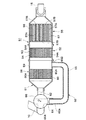
22は排気管10の下流側に設けられた一の酸化触媒装置(以下、第1酸化触媒装置22という)で、該第1酸化触媒装置22は、図4に示すように後述の短絡通路部34を介して流路切換弁35に接続された筒状ケース23と、該筒状ケース23内に収容して設けられた酸化触媒24(通常、Diesel Oxdation Catalyst、略してDOCと呼ばれる)とにより構成されている。   Reference numeral 22 denotes an oxidation catalyst device (hereinafter referred to as a first oxidation catalyst device 22) provided on the downstream side of the exhaust pipe 10, and the first oxidation catalyst device 22 is a short-circuit passage section described later as shown in FIG. A cylindrical case 23 connected to the flow path switching valve 35 via 34, and an oxidation catalyst 24 (usually called Diesel Oxdation Catalyst, abbreviated as DOC) provided in the cylindrical case 23. It is configured.

ここで、酸化触媒24は、図4に示すように、例えば筒状ケース23の内径寸法と同等の外径寸法をもったセラミックス製のセル状筒体からなり、その軸方向には多数の貫通孔24Aが形成され、その内面に貴金属等がコーティングされている。そして、酸化触媒24は、所定の温度下で各貫通孔24Aに排気ガスを流通させることにより、この排気ガスに含まれる一酸化炭素(CO)、炭化水素(HC)等を酸化し二酸化炭素(CO)として除去し、窒素酸化物(NO)を二酸化窒素(NO2)として除去するものである。 Here, as shown in FIG. 4, the oxidation catalyst 24 is made of, for example, a ceramic cellular cylinder having an outer diameter dimension equivalent to the inner diameter dimension of the cylindrical case 23, and has a large number of through holes in the axial direction. A hole 24A is formed, and the inner surface thereof is coated with a noble metal or the like. The oxidation catalyst 24 circulates the exhaust gas through each through-hole 24A at a predetermined temperature, thereby oxidizing carbon monoxide (CO), hydrocarbon (HC), etc. contained in the exhaust gas to carbon dioxide ( CO 2 ) and nitrogen oxide (NO) is removed as nitrogen dioxide (NO 2).

25は第1酸化触媒装置22の下流側に配置されたフィルタ装置で、該フィルタ装置25は、図4に示すように第1酸化触媒装置22の筒状ケース23にフランジ接続された他の筒状ケース26と、該筒状ケース26内に収容して設けられた粒子状物質除去フィルタ27(通常、Diesel Particulate Filterと呼ばれるが、以下、「DPF」27という)とにより構成されている。   Reference numeral 25 denotes a filter device arranged on the downstream side of the first oxidation catalyst device 22, and the filter device 25 is connected to another cylindrical case 23 of the first oxidation catalyst device 22 with a flange as shown in FIG. 4. And a particulate matter removal filter 27 (usually referred to as Diesel Particulate Filter, but hereinafter referred to as “DPF” 27) provided and accommodated in the cylindrical case 26.

ここで、DPF27は、エンジン9から排出される排気ガス中の粒子状物質(PM)を捕集すると共に、捕集した粒子状物質を燃焼して除去することにより排気ガスの浄化を行うものである。また、DPF27は、例えばセラミックス材料等からなる多孔質な部材に軸方向に多数の小孔27Aを設けたセル状筒体により構成され、各小孔27Aは、隣同士で交互に異なる端部が目封じ部材27Bによって閉塞されている。   Here, the DPF 27 collects particulate matter (PM) in the exhaust gas discharged from the engine 9 and purifies the exhaust gas by burning and removing the collected particulate matter. is there. Further, the DPF 27 is configured by a cellular cylindrical body in which a large number of small holes 27A are provided in the axial direction on a porous member made of, for example, a ceramic material, and each small hole 27A has end portions that are alternately adjacent to each other. It is blocked by the sealing member 27B.

これにより、DPF27は、一方から小孔27Aに流入する排気ガスを多孔質材料に通すことで粒子状物質を捕集し、隣の小孔27Aから他方に流出させる。そして、捕集した粒子状物質は、前述の如く燃焼して除去され、これにより、DPF27は再生されるものである。また、フィルタ装置25の筒状ケース26には、その下流側に煙突15が接続して設けられている。そして、フィルタ装置25により浄化処理された後の排気ガスは、煙突15内へと流入して大気中に放出される。   Thus, the DPF 27 collects particulate matter by passing the exhaust gas flowing from one side into the small hole 27A through the porous material, and flows it out from the adjacent small hole 27A to the other. The collected particulate matter is burned and removed as described above, whereby the DPF 27 is regenerated. The cylindrical case 26 of the filter device 25 is provided with a chimney 15 connected to the downstream side thereof. The exhaust gas after being purified by the filter device 25 flows into the chimney 15 and is released into the atmosphere.

28は本実施の形態で採用した他の酸化触媒装置(以下、第2酸化触媒装置28という)を示し、該第2酸化触媒装置28は、後述の連結パイプ32を介して流路切換弁35に接続されたケース筒29と、該ケース筒29内に収容して設けられた他の酸化触媒30(DOC)とにより構成されている。そして、この場合の酸化触媒30は、第1酸化触媒装置22の酸化触媒24と同様に構成されている。   Reference numeral 28 denotes another oxidation catalyst device (hereinafter referred to as a second oxidation catalyst device 28) employed in the present embodiment, and the second oxidation catalyst device 28 is connected to a flow path switching valve 35 via a connecting pipe 32 described later. The case cylinder 29 is connected to the casing cylinder 29, and the other oxidation catalyst 30 (DOC) provided in the case cylinder 29 is provided. In this case, the oxidation catalyst 30 is configured in the same manner as the oxidation catalyst 24 of the first oxidation catalyst device 22.

即ち、酸化触媒30は、図4に示すように、例えばケース筒29の内径寸法と同等の外径寸法をもったセラミックス製のセル状筒体からなり、その軸方向には多数の貫通孔30Aが形成され、内面に貴金属等がコーティングされている。そして、酸化触媒30も、所定の温度下で各貫通孔30Aに排気ガスを流通させることにより、この排気ガスに含まれる一酸化炭素(CO)、炭化水素(HC)等を酸化し二酸化炭素(CO)として除去し、窒素酸化物(NO)を二酸化窒素(NO2)として除去するものである。 That is, as shown in FIG. 4, the oxidation catalyst 30 is made of, for example, a ceramic cell-like cylinder having an outer diameter equivalent to the inner diameter of the case cylinder 29, and has a large number of through holes 30 </ b> A in the axial direction. The inner surface is coated with a noble metal or the like. The oxidation catalyst 30 also oxidizes carbon monoxide (CO), hydrocarbons (HC), etc. contained in the exhaust gas by flowing exhaust gas through each through-hole 30A at a predetermined temperature, and carbon dioxide ( CO 2 ) and nitrogen oxide (NO) is removed as nitrogen dioxide (NO 2).

31は第1酸化触媒装置22と第2酸化触媒装置28とを直列な状態で接続する直列通路部で、該直列通路部31は、後述の連結パイプ32、屈曲パイプ33および第2酸化触媒装置28のケース筒29を含んで構成される。そして、直列通路部31は、後述の流路切換弁35が図5中の戻り位置(A)から切換位置(B)に切換わったときに、第2酸化触媒装置28と第1酸化触媒装置22とをエンジン9の排気管10に対して直列に接続するものである。   31 is a series passage portion that connects the first oxidation catalyst device 22 and the second oxidation catalyst device 28 in series. The series passage portion 31 includes a connecting pipe 32, a bent pipe 33, and a second oxidation catalyst device described later. 28 case cylinders 29 are included. The series passage portion 31 has a second oxidation catalyst device 28 and a first oxidation catalyst device when a flow path switching valve 35 to be described later is switched from the return position (A) in FIG. 5 to the switching position (B). 22 is connected in series to the exhaust pipe 10 of the engine 9.

32は第2酸化触媒装置28の上流側に接続して設けられた連結パイプで、該連結パイプ32は、図3、図4に示す如く第2酸化触媒装置28のケース筒29を後述の流路切換弁35を介して排気管10に接続する。そして、連結パイプ32は、後述の屈曲パイプ33と共に直列通路部31を構成し、流路切換弁35が図5中の戻り位置(A)から切換位置(B)に切換わったときには、第2酸化触媒装置28のケース筒29を排気管10に連通させるものである。   Reference numeral 32 is a connecting pipe provided on the upstream side of the second oxidation catalyst device 28. The connection pipe 32 passes through a case cylinder 29 of the second oxidation catalyst device 28 as described later with reference to FIGS. The exhaust pipe 10 is connected via a path switching valve 35. And the connection pipe 32 comprises the serial channel | path part 31 with the below-mentioned bending pipe 33, and when the flow-path switching valve 35 switches from the return position (A) in FIG. The case cylinder 29 of the oxidation catalyst device 28 is communicated with the exhaust pipe 10.

33は第1酸化触媒装置22と第2酸化触媒装置28との間を接続する屈曲パイプで、該屈曲パイプ33は、図4に示すように略U字状に屈曲して形成され、その一側端部33Aが第2酸化触媒装置28のケース筒29に接続されている。また、屈曲パイプ33の他側端部33Bは、後述の短絡通路部34と酸化触媒24との中間になる位置で、第1酸化触媒装置22の筒状ケース23に径方向から接続されている。   A bent pipe 33 connects the first oxidation catalyst device 22 and the second oxidation catalyst device 28. The bent pipe 33 is formed in a substantially U-shape as shown in FIG. The side end portion 33 </ b> A is connected to the case cylinder 29 of the second oxidation catalyst device 28. Further, the other end 33B of the bent pipe 33 is connected to the cylindrical case 23 of the first oxidation catalyst device 22 from the radial direction at a position between a short-circuit passage 34 and an oxidation catalyst 24, which will be described later. .

そして、屈曲パイプ33は、連結パイプ32と共に直列通路部31を構成し、後述の流路切換弁35が図5中の戻り位置(A)から切換位置(B)に切換わったときには、第2酸化触媒装置28と第1酸化触媒装置22とをエンジン9の排気管10に対して直列に接続するものである。   And the bending pipe 33 comprises the serial passage part 31 with the connection pipe 32, and when the below-mentioned flow-path switching valve 35 switches from the return position (A) in FIG. The oxidation catalyst device 28 and the first oxidation catalyst device 22 are connected in series to the exhaust pipe 10 of the engine 9.

34は第1酸化触媒装置22の上流側に接続して設けられた短絡通路部で、該短絡通路部34は、図3〜図5に示す如く第1酸化触媒装置22の筒状ケース23を後述の流路切換弁35を介して排気管10に直接的に短絡させて接続するものである。そして、短絡通路部34は、後述の流路切換弁35が戻り位置(A)となったときに、第1酸化触媒装置22の筒状ケース23を排気管10に直接的に短絡させて連通させる。   34 is a short-circuit passage portion connected to the upstream side of the first oxidation catalyst device 22, and the short-circuit passage portion 34 connects the cylindrical case 23 of the first oxidation catalyst device 22 as shown in FIGS. 3 to 5. The exhaust pipe 10 is directly short-circuited and connected via a flow path switching valve 35 described later. The short-circuit passage 34 communicates by directly short-circuiting the cylindrical case 23 of the first oxidation catalyst device 22 to the exhaust pipe 10 when a later-described flow path switching valve 35 reaches the return position (A). Let

35は流路の切換えを行う流路切換弁で、該流路切換弁35は、例えば図5に示す如く、後述するコントローラ40からの制御信号により戻り位置(A)と切換位置(B)とに切換制御される。そして、流路切換弁35は、戻り位置(A)となったときに、排気管10からの排気ガスを短絡通路部34を介して第1酸化触媒装置22の筒状ケース23内へと流通させ、連結パイプ32(第2酸化触媒装置28)側に排気ガスが流通するのを遮断する。   Reference numeral 35 denotes a flow path switching valve for switching the flow path. The flow path switching valve 35 is, for example, as shown in FIG. 5, a return position (A) and a switching position (B) according to a control signal from a controller 40 described later. Are controlled to be switched. When the flow path switching valve 35 reaches the return position (A), the exhaust gas from the exhaust pipe 10 flows into the cylindrical case 23 of the first oxidation catalyst device 22 through the short-circuit passage 34. The exhaust gas is blocked from flowing to the connecting pipe 32 (second oxidation catalyst device 28) side.

一方、流路切換弁35は、図5中の戻り位置(A)から切換位置(B)に切換えられたときに、排気管10からの排気ガスを直列通路部31(即ち、連結パイプ32および第2酸化触媒装置28のケース筒29)内に向けて流通させ、短絡通路部34内に向けて排気ガスが流通するのを遮断する。   On the other hand, when the flow path switching valve 35 is switched from the return position (A) to the switching position (B) in FIG. 5, the flow path switching valve 35 allows the exhaust gas from the exhaust pipe 10 to flow through the serial passage portion 31 (that is, the connection pipe 32 and The exhaust gas is allowed to flow into the case cylinder 29) of the second oxidation catalyst device 28, and the exhaust gas is prevented from flowing into the short-circuit passage 34.

この場合、流路切換弁35は、図3、図4中に点線で示すように内部通路35Aを有し、この内部通路35Aは、例えば点Oを中心にして回動されることにより図3、図4に示す如く流路の切換えを行うものである。即ち、流路切換弁35が図5に示す戻り位置(A)となったときには、内部通路35Aが図3に示す位置に配置され、排気管10は短絡通路部34に接続され、直列通路部31(連結パイプ32)側から遮断される。また、流路切換弁35が図5に示す切換位置(B)に切換わったときには、内部通路35Aが図4に示す位置に配置され、排気管10は短絡通路部34から遮断され、直列通路部31(連結パイプ32)側に接続される。   In this case, the flow path switching valve 35 has an internal passage 35A as shown by a dotted line in FIGS. 3 and 4, and this internal passage 35A is rotated around a point O, for example, as shown in FIG. As shown in FIG. 4, the flow path is switched. That is, when the flow path switching valve 35 reaches the return position (A) shown in FIG. 5, the internal passage 35A is disposed at the position shown in FIG. 3, the exhaust pipe 10 is connected to the short-circuit passage portion 34, and the serial passage portion. It is cut off from the 31 (connection pipe 32) side. When the flow path switching valve 35 is switched to the switching position (B) shown in FIG. 5, the internal passage 35A is arranged at the position shown in FIG. It is connected to the part 31 (connection pipe 32) side.

36は排気ガスの温度を検出するための温度センサで、該温度センサ36は、図5に示すように、例えば流路切換弁35と排気管10との間に配置され、排気管10から排出される排気ガスの温度Tを検出する。そして、温度センサ36で検出した温度Tは、検出信号として後述のコントローラ40に出力されるものである。   Reference numeral 36 denotes a temperature sensor for detecting the temperature of the exhaust gas. The temperature sensor 36 is disposed, for example, between the flow path switching valve 35 and the exhaust pipe 10 as shown in FIG. The temperature T of the exhaust gas to be detected is detected. The temperature T detected by the temperature sensor 36 is output to the controller 40 described later as a detection signal.

37,38はフィルタ装置25に設けられた圧力センサで、この圧力センサ37,38は、DPF27(図4参照)の上流側と下流側とに離間して配置され、それぞれの検出信号をコントローラ40に出力する。そして、コントローラ40は、圧力センサ37で検出した上流側の圧力P1 (図6参照)と圧力センサ38で検出した下流側の圧力P2 とにより、後述の差圧ΔPを演算し、この演算結果からDPF27(図4参照)に付着した粒子状物質、未燃焼残留物等の堆積量を推定するものである。   Reference numerals 37 and 38 denote pressure sensors provided in the filter device 25. The pressure sensors 37 and 38 are arranged on the upstream side and the downstream side of the DPF 27 (see FIG. 4), and the respective detection signals are sent to the controller 40. Output to. Then, the controller 40 calculates a differential pressure ΔP, which will be described later, from the upstream pressure P1 (see FIG. 6) detected by the pressure sensor 37 and the downstream pressure P2 detected by the pressure sensor 38. This is to estimate the amount of particulate matter, unburned residue, etc. deposited on the DPF 27 (see FIG. 4).

39はエンジン9の回転数を検出する回転センサで、この回転センサ39は、エンジン回転数Nを検出し、その検出信号をコントローラ40に出力する。そして、コントローラ40は、エンジン回転数Nの検出信号に基づいてエンジン9の運転状態を判別するものである。   Reference numeral 39 denotes a rotation sensor for detecting the rotation speed of the engine 9. The rotation sensor 39 detects the engine rotation speed N and outputs a detection signal to the controller 40. Then, the controller 40 determines the operating state of the engine 9 based on the detection signal of the engine speed N.

40はマイクロコンピュータ等からなる制御手段としてのコントローラで、該コントローラ40は、その入力側が温度センサ36、圧力センサ37,38および回転センサ39等に接続され、その出力側はエンジン9および流路切換弁35等に接続されている。また、コントローラ40は、ROM,RAM等からなる記憶部40Aを有し、この記憶部40A内には、後述の図6に示す流路切換制御用の処理プログラムと、予め決められたエンジン回転数Nの判定値Nt、圧力の判定値Pt、基準温度Ta等とが格納されている。   Reference numeral 40 denotes a controller as a control means composed of a microcomputer or the like. The controller 40 has an input side connected to a temperature sensor 36, pressure sensors 37 and 38, a rotation sensor 39, etc., and an output side connected to the engine 9 and flow path switching. It is connected to the valve 35 and the like. Further, the controller 40 has a storage unit 40A composed of a ROM, a RAM, and the like, and in this storage unit 40A, a processing program for flow path switching control shown in FIG. N determination value Nt, pressure determination value Pt, reference temperature Ta, and the like are stored.

ここで、エンジン回転数Nの判定値Ntとは、例えばエンジン9の定格回転数等から決められる回転数であり、エンジン回転数Nが判定値Nt以下となったときには、エンジン9は軽負荷状態で運転される可能性が高くなるものである。また、圧力の判定値Ptは、フィルタ装置25のDPF27(図4参照)に付着した粒子状物質、未燃焼残留物等の堆積量を推定するための判定値であり、後述の差圧ΔPが判定値Pt以上となったときに、前記堆積量が多くなってフィルタ(DPF27)の再生処理が必要と判定することができる。また、基準温度Taは、Ta=240〜280℃の温度範囲内に設定されるものである。   Here, the determination value Nt of the engine speed N is, for example, a speed determined from the rated speed of the engine 9 or the like, and when the engine speed N becomes equal to or less than the determination value Nt, the engine 9 is in a light load state. There is a high possibility of being driven by. Further, the pressure determination value Pt is a determination value for estimating the amount of accumulation of particulate matter, unburned residue, and the like attached to the DPF 27 (see FIG. 4) of the filter device 25. When the determination value Pt or more is reached, it can be determined that the amount of accumulation increases and the regeneration process of the filter (DPF 27) is necessary. The reference temperature Ta is set within a temperature range of Ta = 240 to 280 ° C.

そして、コントローラ40は、後述する図6の処理プログラムに従って排気管10を、直列通路部31と短絡通路部34とのいずれか一方に選択的に接続する流路切換制御を行う。即ち、コントローラ40は、回転センサ39、圧力センサ37,38および温度センサ36からの検出信号により、フィルタ装置25のDPF27(図4参照)に付着した粒子状物質、未燃焼残留物等の堆積量が多くなり、これらを燃焼により焼き切ってDPF27の再生を行う必要があり、しかも排気ガスの温度Tが基準温度Taよりも低いと判定したときに、流路切換弁35を戻り位置(A)から切換位置(B)に切換える制御を行うものである。   Then, the controller 40 performs flow path switching control for selectively connecting the exhaust pipe 10 to either one of the series passage portion 31 and the short-circuit passage portion 34 in accordance with the processing program of FIG. That is, the controller 40 uses the detection signals from the rotation sensor 39, the pressure sensors 37 and 38, and the temperature sensor 36 to deposit the particulate matter, unburned residue, and the like attached to the DPF 27 (see FIG. 4) of the filter device 25. When the exhaust gas temperature T is determined to be lower than the reference temperature Ta, it is necessary to regenerate the DPF 27 by burning them out by combustion, and the flow path switching valve 35 is returned to the return position (A). The control to switch from to the switching position (B) is performed.

本実施の形態による小型の油圧ショベル1に搭載された排気ガス浄化装置21は、上述の如き構成を有するもので、次に、その動作について説明する。   The exhaust gas purifying device 21 mounted on the small-sized hydraulic excavator 1 according to the present embodiment has the above-described configuration. Next, the operation thereof will be described.

まず、油圧ショベル1のオペレータは、上部旋回体4のキャブ8に搭乗し、エンジン9を始動して油圧ポンプ11を駆動する。これにより、油圧ポンプ11からの圧油は、制御弁を介して各種アクチュエータに供給される。そして、キャブ8に搭乗したオペレータが走行用の操作レバー(図示せず)を操作したときには、下部走行体2を前進または後退させることができる。   First, the operator of the hydraulic excavator 1 gets on the cab 8 of the upper swing body 4, starts the engine 9, and drives the hydraulic pump 11. Thereby, the pressure oil from the hydraulic pump 11 is supplied to various actuators via the control valve. And when the operator who boarded the cab 8 operated the operation lever (not shown) for driving | running | working, the lower traveling body 2 can be moved forward or backward.

一方、キャブ8内のオペレータが作業用の操作レバー(図示せず)を操作することにより、作業装置5を俯仰動させて土砂の掘削作業等を行うことができる。また、小型の油圧ショベル1は、上部旋回体4による旋回半径が小さいため、例えば市街地等のように狭い作業現場でも、上部旋回体4を旋回駆動しながら側溝堀作業等を行うことができ、このような場合には、エンジン9を負荷の軽い状態で稼働することにより騒音の低減化を図るものである。   On the other hand, when an operator in the cab 8 operates an operation lever (not shown) for work, the work device 5 can be moved up and down to perform excavation work of earth and sand. Further, since the small excavator 1 has a small turning radius due to the upper swing body 4, it is possible to perform a side ditching operation while driving the upper swing body 4 while turning the upper swing body 4 even in a narrow work site such as an urban area. In such a case, noise is reduced by operating the engine 9 with a light load.

また、エンジン9の運転時には、その排気管10から有害物質である粒子状物質等が排出される。このときに排気ガス浄化装置21は、例えば第1酸化触媒装置22によって排気ガス中の炭化水素(HC)、窒素酸化物(NO)、一酸化炭素(CO)を酸化除去することができる。そして、フィルタ装置25は、図4に示すDPF27によって粒子状物質を捕集し、捕集した粒子状物質を燃焼して除去(再生)する。これにより、浄化した排気ガスを下流側の煙突15から外部に排出することができる。   Further, when the engine 9 is operated, particulate matter or the like which is a harmful substance is discharged from the exhaust pipe 10. At this time, the exhaust gas purification device 21 can oxidize and remove hydrocarbons (HC), nitrogen oxides (NO), and carbon monoxide (CO) in the exhaust gas, for example, by the first oxidation catalyst device 22. The filter device 25 collects the particulate matter by the DPF 27 shown in FIG. 4 and burns and removes (regenerates) the collected particulate matter. As a result, the purified exhaust gas can be discharged from the downstream chimney 15 to the outside.

ところで、小型でコンパクトな構造となった小旋回式(小型)の油圧ショベル1は、大型、中型の機種等に比較して作業装置5による土砂の掘削力、走行能力等が相対的に小さく、エンジン9も比較的小型となっている。しかも、この場合のエンジン9は軽負荷状態で運転することが多いので、例えば排気ガスの温度が前述した基準温度よりも下がってしまう。   By the way, the small swivel (small) hydraulic excavator 1 having a small and compact structure is relatively small in excavation force, traveling ability, etc. of earth and sand by the working device 5 as compared with large and medium-sized models. The engine 9 is also relatively small. In addition, since the engine 9 in this case is often operated in a light load state, for example, the temperature of the exhaust gas falls below the reference temperature described above.

このため、例えば第1酸化触媒装置22のみを通過した排気ガスを下流側のフィルタ装置25に導いた場合には、フィルタ装置25内に流入する排気ガスの温度を所要の温度まで上昇させるのが難しくなり、DPF27に堆積した粒子状物質を燃焼させてDPF27を再生することが困難になることがある。   For this reason, for example, when exhaust gas that has passed only through the first oxidation catalyst device 22 is led to the downstream filter device 25, the temperature of the exhaust gas flowing into the filter device 25 is raised to a required temperature. It may become difficult to regenerate the DPF 27 by burning the particulate matter deposited on the DPF 27.

そこで、第1の実施の形態では、排気管10を基準にして第1酸化触媒装置22よりも上流側となる位置に、第1酸化触媒装置22と第2酸化触媒装置28とを直列に接続する直列通路部31と、第1酸化触媒装置22に短絡して接続される短絡通路部34とを設け、この直列通路部31と短絡通路部34とに対する排気ガスの流れを流路切換弁35により選択的に切換える構成としている。   Therefore, in the first embodiment, the first oxidation catalyst device 22 and the second oxidation catalyst device 28 are connected in series at a position upstream of the first oxidation catalyst device 22 with respect to the exhaust pipe 10. A series passage portion 31 that is connected to the first oxidation catalyst device 22 and a short-circuit passage portion 34 that is short-circuited to the first oxidation catalyst device 22, and the flow of the exhaust gas to the series passage portion 31 and the short-circuit passage portion 34 is changed to a flow path switching valve 35. It is configured to selectively switch by.

そして、コントローラ40は、図6に示す処理プログラム従って流路切換弁35を、戻り位置(A)と切換位置(B)とのいずれか一方に切換制御し、これにより、フィルタ装置25のDPF27を安定して再生させる構成としたものである。   Then, the controller 40 controls to switch the flow path switching valve 35 to either one of the return position (A) and the switching position (B) according to the processing program shown in FIG. 6, thereby the DPF 27 of the filter device 25 is controlled. It is configured to reproduce stably.

即ち、エンジン9の稼働により図6の処理動作がスタートすると、ステップ1では回転センサ39からエンジン回転数Nを読込む。次に、ステップ2では、エンジン回転数Nが予め決められた判定値Nt以下であるか否かを判定する。そして、ステップ2で「NO」と判定する間は、エンジン回転数Nが十分に高く、エンジン9は高負荷状態で運転される可能性が高くなるものである。   That is, when the processing operation of FIG. 6 is started by the operation of the engine 9, in step 1, the engine speed N is read from the rotation sensor 39. Next, in step 2, it is determined whether or not the engine speed N is equal to or less than a predetermined determination value Nt. During the determination of “NO” in step 2, the engine speed N is sufficiently high, and the engine 9 is likely to be operated in a high load state.

そこで、ステップ2で「NO」と判定するときには、次なるステップ3に移って流路切換弁35を戻り位置(A)として短絡通路部34側に切換制御し、排気管10からの排気ガスを第1酸化触媒装置22に直接的に流通させる。そして、次なるステップ4でリターンし、その後はステップ1以降の処理を繰返すようにする。   Therefore, when it is determined “NO” in step 2, the process proceeds to the next step 3 where the flow path switching valve 35 is set to the return position (A) and switched to the short-circuit passage 34 side, and the exhaust gas from the exhaust pipe 10 is discharged. It is made to distribute | circulate directly to the 1st oxidation catalyst apparatus 22. FIG. Then, the process returns at the next step 4, and thereafter, the processes after step 1 are repeated.

一方、ステップ2で「YES」と判定したときには、エンジン回転数Nが判定値Nt以下となって、エンジン9は軽負荷状態で運転される可能性が高くなっている。そこで、この場合には、次なるステップ5に移って圧力センサ37,38から圧力P1 ,P2 を読込む。即ち、フィルタ装置25のDPF27(図4参照)に対し、その上流側の圧力P1 と下流側の圧力P2 とを読込む。   On the other hand, when “YES” is determined in Step 2, the engine speed N is equal to or lower than the determination value Nt, and the engine 9 is likely to be operated in a light load state. In this case, therefore, the process proceeds to the next step 5 where the pressures P1, P2 are read from the pressure sensors 37, 38. That is, the upstream side pressure P1 and the downstream side pressure P2 are read into the DPF 27 (see FIG. 4) of the filter device 25.

そして、次なるステップ6では、DPF27の上流側の圧力P1 と下流側の圧力P2 との差圧ΔPを、下記の数1式により演算する。そして、次のステップ7では、差圧ΔPが予め決められた判定値Pt以上となっているか否かを判定する。   In the next step 6, the differential pressure ΔP between the upstream pressure P1 and the downstream pressure P2 of the DPF 27 is calculated by the following equation (1). Then, in the next step 7, it is determined whether or not the differential pressure ΔP is greater than or equal to a predetermined determination value Pt.

Figure 2010236363
Figure 2010236363

ここで、ステップ7により「NO」と判定するときには、前記差圧ΔPが小さく、フィルタ装置25のDPF27(図4参照)には粒子状物質、未燃焼残留物等がそれほどには堆積してないと判断することができる。そこで、この場合もステップ3に移って流路切換弁35を戻り位置(A)として短絡通路部34側に切換制御し、排気管10からの排気ガスを第1酸化触媒装置22に直接的に流通させる。そして、次なるステップ4でリターンし、その後はステップ1以降の処理を繰返すようにする。   Here, when “NO” is determined in step 7, the differential pressure ΔP is small, and particulate matter, unburned residue, and the like are not deposited so much on the DPF 27 (see FIG. 4) of the filter device 25. It can be judged. Therefore, also in this case, the process proceeds to step 3 where the flow path switching valve 35 is set to the return position (A) and switched to the short-circuit passage 34 side, and the exhaust gas from the exhaust pipe 10 is directly supplied to the first oxidation catalyst device 22. Circulate. Then, the process returns at the next step 4, and thereafter, the processes after step 1 are repeated.

一方、ステップ7で「YES」と判定したときには、差圧ΔPが判定値Pt以上となって、フィルタ装置25のDPF27に付着した粒子状物質、未燃焼残留物等の堆積量が多くなっていると判断することができる。このため、次なるステップ8では、温度センサ36から排気ガスの温度Tを読込む。そして、ステップ9に移って、排気ガスの温度Tが基準温度Ta(例えば、Ta=240〜280℃)よりも低いか否かを判定する。   On the other hand, when “YES” is determined in Step 7, the differential pressure ΔP becomes equal to or greater than the determination value Pt, and the accumulation amount of particulate matter, unburned residue, and the like attached to the DPF 27 of the filter device 25 is increased. It can be judged. Therefore, in the next step 8, the temperature T of the exhaust gas is read from the temperature sensor 36. Then, the process proceeds to step 9 to determine whether or not the temperature T of the exhaust gas is lower than a reference temperature Ta (for example, Ta = 240 to 280 ° C.).

この場合、ステップ9で「NO」と判定するときには、排気ガスの温度Tが基準温度Ta以上となって高いため、フィルタ装置25のDPF27に捕集した粒子状物質等を燃焼して除去する上で、燃焼温度が不足することはないと判断することができる。従って、この場合もステップ3に移って流路切換弁35を戻り位置(A)として短絡通路部34側に切換制御し、排気管10からの排気ガスを第1酸化触媒装置22に直接的に流通させる。そして、次なるステップ4でリターンし、その後はステップ1以降の処理を繰返すようにする。   In this case, when “NO” is determined in step 9, since the exhaust gas temperature T is higher than the reference temperature Ta, the particulate matter collected in the DPF 27 of the filter device 25 is burned and removed. Thus, it can be determined that the combustion temperature is not insufficient. Accordingly, in this case as well, the process proceeds to step 3 where the flow path switching valve 35 is set to the return position (A) and switched to the short-circuit passage 34 side, and the exhaust gas from the exhaust pipe 10 is directly supplied to the first oxidation catalyst device 22. Circulate. Then, the process returns at the next step 4, and thereafter, the processes after step 1 are repeated.

一方、ステップ9で「YES」と判定したときには、排気ガスの温度Tが基準温度Taよりも低いために、フィルタ装置25のDPF27に捕集した粒子状物質等を燃焼して除去する上で、燃焼温度が不足する可能性が高い。そこで、この場合には、ステップ10に移って流路切換弁35を戻り位置(A)から切換位置(B)に切換え、直列通路部31側に切換える制御を行う。   On the other hand, when it is determined as “YES” in step 9, since the exhaust gas temperature T is lower than the reference temperature Ta, the particulate matter collected in the DPF 27 of the filter device 25 is burned and removed. The combustion temperature is likely to be insufficient. Therefore, in this case, the process proceeds to step 10 where the flow path switching valve 35 is switched from the return position (A) to the switching position (B) and switched to the series passage portion 31 side.

これにより、排気管10からの排気ガスは、短絡通路部34内に流通するのが遮断され、連結パイプ32側から第2酸化触媒装置28を経由して第1酸化触媒装置22へと流通する。このため、排気ガス中の成分は、図4中に示すように2つの酸化触媒30,24を通過することにより、それぞれの酸化触媒30,24で反応を繰返し、例えば炭化水素(HC)を酸化するとき等に排気ガスの温度を上昇させることができる。   As a result, the exhaust gas from the exhaust pipe 10 is blocked from flowing into the short-circuit passage portion 34 and flows from the connecting pipe 32 side to the first oxidation catalyst device 22 via the second oxidation catalyst device 28. . Therefore, the components in the exhaust gas pass through the two oxidation catalysts 30 and 24 as shown in FIG. 4 to repeat the reaction in the respective oxidation catalysts 30 and 24, for example, oxidize hydrocarbon (HC). When doing so, the temperature of the exhaust gas can be raised.

しかも、この場合の排気ガスは、直列状態となった2つの酸化触媒30,24により大きな絞り抵抗を受けて圧損が増大し、エンジン9の負荷が増加する。これにより、エンジン9は燃料の噴射量を増やすことになり、これに伴って排気ガスの温度をさらに上昇することができる。   In addition, the exhaust gas in this case is subjected to a large throttle resistance by the two oxidation catalysts 30 and 24 in a series state, and the pressure loss increases, and the load on the engine 9 increases. As a result, the engine 9 increases the fuel injection amount, and accordingly, the temperature of the exhaust gas can be further increased.

この結果、第1酸化触媒装置22の下流側に位置するフィルタ装置25に対しては、温度の高い排気ガスを導くことができ、例えばDPF27を再生するときの燃焼温度を高くすることができる。これによって、DPF27内に堆積した粒子状物質を焼き切ることができ、DPF27の再生を円滑に行うことができる。   As a result, the exhaust gas having a high temperature can be guided to the filter device 25 located on the downstream side of the first oxidation catalyst device 22, and for example, the combustion temperature when the DPF 27 is regenerated can be increased. Thereby, the particulate matter deposited in the DPF 27 can be burned out, and the DPF 27 can be regenerated smoothly.

また、ステップ10の処理後はステップ8に戻って、これ以降の処理を繰返すようにする。そして、ステップ9で「YES」と判定する間は、流路切換弁35を切換位置(B)に切換えた状態に保ち、排気管10からの排気ガスを連結パイプ32、第2酸化触媒装置28を経由して第1酸化触媒装置22へと流通させる。   In addition, after the process of step 10, the process returns to step 8, and the subsequent processes are repeated. While the determination at step 9 is “YES”, the flow path switching valve 35 is kept switched to the switching position (B), and the exhaust gas from the exhaust pipe 10 is connected to the connecting pipe 32 and the second oxidation catalyst device 28. Through the first oxidation catalyst device 22.

一方、ステップ9で「NO」と判定したときには、排気ガスの温度Tが基準温度Ta以上となっているため、燃焼温度が不足することはないと判断できる。従って、この場合はステップ3に移って流路切換弁35を戻り位置(A)とし、排気管10からの排気ガスを第1酸化触媒装置22に直接的に流通させ、その後はステップ4でリターンする。   On the other hand, when it is determined as “NO” in step 9, it can be determined that the combustion temperature is not insufficient because the temperature T of the exhaust gas is equal to or higher than the reference temperature Ta. Therefore, in this case, the process proceeds to step 3 where the flow path switching valve 35 is set to the return position (A), and the exhaust gas from the exhaust pipe 10 is directly circulated to the first oxidation catalyst device 22. To do.

かくして、本実施の形態によれば、排気管10の下流側に流路切換弁35を介して直列通路部31と短絡通路部34とを設け、短絡通路部34は第1酸化触媒装置22に直接的に短絡して接続され、直列通路部31側には、第1酸化触媒装置22よりも上流側となる位置に屈曲パイプ33を介して第2酸化触媒装置28を直列に接続して設け、直列通路部31と短絡通路部34とに対する排気ガスの流れを流路切換弁35により選択的に切換える構成としている。   Thus, according to the present embodiment, the serial passage portion 31 and the short-circuit passage portion 34 are provided on the downstream side of the exhaust pipe 10 via the flow path switching valve 35, and the short-circuit passage portion 34 is connected to the first oxidation catalyst device 22. The second oxidation catalyst device 28 is connected in series via a bent pipe 33 at a position upstream of the first oxidation catalyst device 22 on the series passage 31 side. The flow of the exhaust gas to the series passage portion 31 and the short-circuit passage portion 34 is selectively switched by the flow path switching valve 35.

そして、エンジン9から排出される排気ガスの温度Tが基準温度Taよりも低いときには、この排気ガスを直列通路部31側に導いて第2酸化触媒装置28と第1酸化触媒装置22とに流通させる。これにより、排気ガスは2つの酸化触媒装置28,22から大きな絞り抵抗を受けて圧損が増大し、エンジン9の負荷が増加するので、エンジン9は燃料の噴射量を増やすようになり、これに伴って排気ガスの温度を上昇することができる。しかも、2つの酸化触媒装置28,22による酸化触媒反応によっても排気ガスの温度を上昇することができる。   When the temperature T of the exhaust gas discharged from the engine 9 is lower than the reference temperature Ta, the exhaust gas is led to the series passage portion 31 side and is distributed to the second oxidation catalyst device 28 and the first oxidation catalyst device 22. Let As a result, the exhaust gas receives a large throttle resistance from the two oxidation catalyst devices 28 and 22 and the pressure loss increases and the load on the engine 9 increases, so the engine 9 increases the fuel injection amount. Along with this, the temperature of the exhaust gas can be increased. In addition, the temperature of the exhaust gas can be increased by an oxidation catalyst reaction by the two oxidation catalyst devices 28 and 22.

この結果、第1酸化触媒装置22の下流側に位置するフィルタ装置25に対しては、温度の高い排気ガスを導くことができ、例えばDPF27を再生するときの燃焼温度を高くすることができる。これによって、DPF27内に堆積した粒子状物質を焼き切ることができ、DPF27の再生を円滑に行うことができる。   As a result, the exhaust gas having a high temperature can be guided to the filter device 25 located on the downstream side of the first oxidation catalyst device 22, and for example, the combustion temperature when the DPF 27 is regenerated can be increased. Thereby, the particulate matter deposited in the DPF 27 can be burned out, and the DPF 27 can be regenerated smoothly.

また、エンジン9から排出される排気ガスの温度Tが基準温度Taを越えるようなときには、流路切換弁35を戻り位置(A)に保持することにより、第2酸化触媒装置28に対する排気ガスの流れを遮断でき、第1酸化触媒装置22に排気ガスを直接的に流通させることにより、フィルタ装置25においてDPF27の再生を行うことができる。   Further, when the temperature T of the exhaust gas discharged from the engine 9 exceeds the reference temperature Ta, the exhaust gas to the second oxidation catalyst device 28 is kept by holding the flow path switching valve 35 at the return position (A). The flow can be interrupted, and the DPF 27 can be regenerated in the filter device 25 by allowing the exhaust gas to flow directly through the first oxidation catalyst device 22.

従って、第1の実施の形態によれば、エンジン9の軽負荷運転により排気ガスの温度が下がったときでも、フィルタ装置25のDPF27に堆積した粒子状物質を燃焼させてDPF27を再生することができ、排気ガスの浄化処理を安定して行うことができ、これにより、排気ガス浄化装置21としての信頼性を向上することができる。   Therefore, according to the first embodiment, even when the temperature of the exhaust gas decreases due to the light load operation of the engine 9, the particulate matter deposited on the DPF 27 of the filter device 25 is burned to regenerate the DPF 27. In addition, the exhaust gas purification process can be performed stably, whereby the reliability of the exhaust gas purification device 21 can be improved.

次に、図7および図8は本発明の第2の実施の形態を示し、本実施の形態の特徴は、2つの酸化触媒装置を直接的に突合わせて接続する構成とし、このうち下流側に位置する酸化触媒装置には、屈曲パイプからなる短絡通路部を介して排気ガスを直接的に導ける構成としたことにある。なお、第2の実施の形態では、前述した第1の実施の形態と同一の構成要素に同一の符号を付し、その説明を省略するものとする。   Next, FIG. 7 and FIG. 8 show a second embodiment of the present invention, and the feature of this embodiment is a configuration in which two oxidation catalyst devices are directly abutted and connected, of which the downstream side In the oxidation catalyst device located at, the exhaust gas can be directly guided through a short-circuit passage portion formed of a bent pipe. In the second embodiment, the same components as those in the first embodiment are denoted by the same reference numerals, and the description thereof is omitted.

図中、51は第2の実施の形態による排気ガス浄化装置を示し、該排気ガス浄化装置51は、第1の実施の形態で述べた排気ガス浄化装置21とほぼ同様に構成され、後述の第1酸化触媒装置52、フィルタ装置55、第2酸化触媒装置58および流路切換弁66を有している。しかし、この場合の排気ガス浄化装置51は、後述する2つの酸化触媒装置52,58が直接的に突合わせるように接続されている点で、第1の実施の形態とは異なっている。   In the figure, reference numeral 51 denotes an exhaust gas purification device according to the second embodiment. The exhaust gas purification device 51 is configured in substantially the same manner as the exhaust gas purification device 21 described in the first embodiment, and will be described later. A first oxidation catalyst device 52, a filter device 55, a second oxidation catalyst device 58, and a flow path switching valve 66 are provided. However, the exhaust gas purification device 51 in this case is different from the first embodiment in that two oxidation catalyst devices 52 and 58 described later are connected so as to directly face each other.

52は一の酸化触媒装置(以下、第1酸化触媒装置52という)で、該第1酸化触媒装置52は、第1の実施の形態で述べた第1酸化触媒装置22と同様に構成され、図8に示すように筒状ケース53と、多数の貫通孔54Aを有した酸化触媒54(DOC)とを備えている。しかし、この場合の第1酸化触媒装置52は、筒状ケース53が円筒状の筒体として形成され、その両端が後述の筒状ケース56,59間に挟まれた状態でフランジ接続されている。   52 is one oxidation catalyst device (hereinafter referred to as a first oxidation catalyst device 52), and the first oxidation catalyst device 52 is configured in the same manner as the first oxidation catalyst device 22 described in the first embodiment, As shown in FIG. 8, a cylindrical case 53 and an oxidation catalyst 54 (DOC) having a large number of through holes 54A are provided. However, in the first oxidation catalyst device 52 in this case, the cylindrical case 53 is formed as a cylindrical cylindrical body, and both ends thereof are flange-connected with being sandwiched between cylindrical cases 56 and 59 described later. .

55は第1酸化触媒装置52の下流側に配置されたフィルタ装置で、該フィルタ装置55は、第1の実施の形態で述べたフィルタ装置25と同様に構成され、図8に示すように第1酸化触媒装置52の筒状ケース53にフランジ接続された他の筒状ケース56と、該筒状ケース56内に収容して設けられ多数の小孔57A、目封じ部材57Bを有したDPF57とを備えている。また、フィルタ装置55の筒状ケース56にも、その下流側に煙突15が接続して設けられている。   55 is a filter device arranged on the downstream side of the first oxidation catalyst device 52. The filter device 55 is configured in the same manner as the filter device 25 described in the first embodiment, and as shown in FIG. Another cylindrical case 56 flange-connected to the cylindrical case 53 of the oxidation catalyst device 52; a DPF 57 having a large number of small holes 57A and a sealing member 57B provided in the cylindrical case 56; It has. Further, the chimney 15 is also provided on the downstream side of the cylindrical case 56 of the filter device 55.

58は本実施の形態で採用した他の酸化触媒装置(以下、第2酸化触媒装置58という)で、該第2酸化触媒装置58は、後述の連結パイプ62を介して流路切換弁66に接続された別の筒状ケース59と、該筒状ケース59内に収容して設けられた他の酸化触媒60(DOC)とにより構成されている。そして、この場合の酸化触媒60は、第1酸化触媒装置52の酸化触媒54と同様に構成されている。   Reference numeral 58 denotes another oxidation catalyst device (hereinafter referred to as a second oxidation catalyst device 58) employed in the present embodiment, and the second oxidation catalyst device 58 is connected to the flow path switching valve 66 via a connecting pipe 62 described later. It is constituted by another cylindrical case 59 connected and another oxidation catalyst 60 (DOC) provided in the cylindrical case 59. In this case, the oxidation catalyst 60 is configured in the same manner as the oxidation catalyst 54 of the first oxidation catalyst device 52.

即ち、酸化触媒60は、図8に示すように、例えば筒状ケース59の内径寸法と同等の外径寸法をもったセラミックス製のセル状筒体からなり、その軸方向には多数の貫通孔60Aが形成され、内面に貴金属等がコーティングされている。そして、酸化触媒60も、所定の温度下で各貫通孔60Aに排気ガスを流通させることにより、この排気ガスに含まれる一酸化炭素(CO)、炭化水素(HC)等を酸化して除去し、窒素酸化物(NO)を二酸化窒素(NO2)として除去するものである。   That is, as shown in FIG. 8, the oxidation catalyst 60 is formed of a ceramic cylindrical tube having an outer diameter equivalent to the inner diameter of the cylindrical case 59, for example. 60A is formed, and the inner surface is coated with a noble metal or the like. The oxidation catalyst 60 also oxidizes and removes carbon monoxide (CO), hydrocarbons (HC), etc. contained in the exhaust gas by circulating the exhaust gas through the through holes 60A at a predetermined temperature. Nitrogen oxide (NO) is removed as nitrogen dioxide (NO2).

61は第1酸化触媒装置52と第2酸化触媒装置58を直列に接続する直列通路部で、該直列通路部61は、後述の連結パイプ62と第2酸化触媒装置58の筒状ケース59とを含んで構成される。そして、直列通路部61は、後述する流路切換弁66の内部通路66Aが図7中に点線で示す位置に切換わったときに、第2酸化触媒装置58と第1酸化触媒装置52とをエンジン9の排気管10に対して直列に接続するものである。   61 is a series passage portion for connecting the first oxidation catalyst device 52 and the second oxidation catalyst device 58 in series. The series passage portion 61 includes a connecting pipe 62 and a cylindrical case 59 of the second oxidation catalyst device 58 which will be described later. It is comprised including. The series passage portion 61 connects the second oxidation catalyst device 58 and the first oxidation catalyst device 52 when an internal passage 66A of a flow path switching valve 66 described later is switched to a position indicated by a dotted line in FIG. The exhaust pipe 10 of the engine 9 is connected in series.

62は第2酸化触媒装置58の上流側に接続して設けられた連結パイプで、該連結パイプ62は、図7、図8に示す如く第2酸化触媒装置58の筒状ケース59等と共に直列通路部61を構成するものである。   62 is a connecting pipe provided on the upstream side of the second oxidation catalyst device 58. The connection pipe 62 is connected in series with the cylindrical case 59 of the second oxidation catalyst device 58 as shown in FIGS. The passage portion 61 is configured.

63は第1酸化触媒装置52の筒状ケース53を排気管10に短絡して接続する短絡通路部で、該短絡通路部63は、連結パイプ64と屈曲パイプ65とを含んで構成されている。ここで、屈曲パイプ65は、図7、図8に示すように略U字状またはコ字状に屈曲して形成され、その一側端部65Aが後述の流路切換弁66に連結パイプ64を介して接続されている。また、屈曲パイプ65の他側端部65Bは、図8に示すように第1酸化触媒装置52の酸化触媒54よりも上流側となり、第2酸化触媒装置58の酸化触媒60よりも下流側となる位置で筒状ケース59に径方向から接続されている。   Reference numeral 63 denotes a short-circuit passage portion that short-circuits and connects the cylindrical case 53 of the first oxidation catalyst device 52 to the exhaust pipe 10. The short-circuit passage portion 63 includes a connection pipe 64 and a bent pipe 65. . Here, the bent pipe 65 is formed to be bent in a substantially U shape or U shape as shown in FIGS. 7 and 8, and one end portion 65 </ b> A thereof is connected to a flow path switching valve 66 described later. Connected through. Further, the other end 65B of the bent pipe 65 is upstream of the oxidation catalyst 54 of the first oxidation catalyst device 52 and downstream of the oxidation catalyst 60 of the second oxidation catalyst device 58, as shown in FIG. At this position, it is connected to the cylindrical case 59 from the radial direction.

そして、屈曲パイプ65は、後述する流路切換弁66の内部通路66Aが図8中に点線で示すように切換わったときに、第1酸化触媒装置52の筒状ケース53を排気管10に直接的に短絡させて接続するものである。これにより、屈曲パイプ65と連結パイプ64とは短絡通路部63を構成し、第1酸化触媒装置52を排気管10側に流路切換弁66を介して直接的に連通させる。   Then, the bent pipe 65 causes the cylindrical case 53 of the first oxidation catalyst device 52 to the exhaust pipe 10 when an internal passage 66A of a flow path switching valve 66 described later is switched as indicated by a dotted line in FIG. It is directly short-circuited and connected. As a result, the bent pipe 65 and the connecting pipe 64 constitute a short-circuit passage portion 63, and the first oxidation catalyst device 52 is directly communicated to the exhaust pipe 10 side via the flow path switching valve 66.

66は流路切換弁を構成する流路切換弁で、該流路切換弁66は、第1の実施の形態で述べた流路切換弁35とほぼ同様に構成され、コントローラ(図示せず)からの制御信号により切換制御される。この場合、流路切換弁66は、図7、図8中に点線で示すように内部通路66Aを有し、この内部通路66Aは、例えば点Oを中心にして回動されることにより図7、図8に示す如く流路の切換えを行うものである。   Reference numeral 66 denotes a flow path switching valve constituting the flow path switching valve. The flow path switching valve 66 is configured in substantially the same manner as the flow path switching valve 35 described in the first embodiment, and is a controller (not shown). Is controlled by a control signal from. In this case, the flow path switching valve 66 has an internal passage 66A as shown by a dotted line in FIGS. 7 and 8, and this internal passage 66A is rotated around a point O, for example, as shown in FIG. As shown in FIG. 8, the flow path is switched.

即ち、流路切換弁66は、内部通路66Aが図7に示す位置に配置されたときに、排気管10を直列通路部61(連結パイプ62)側に接続し、連結パイプ64側からは遮断する。これにより、排気管10からの排気ガスは、連結パイプ62を介して第2酸化触媒装置58の筒状ケース59内に向けて流通し、その後に第1酸化触媒装置52の筒状ケース53内に向けて流通する。   That is, the flow path switching valve 66 connects the exhaust pipe 10 to the series passage portion 61 (connection pipe 62) side and shuts off from the connection pipe 64 side when the internal passage 66A is disposed at the position shown in FIG. To do. As a result, the exhaust gas from the exhaust pipe 10 circulates into the cylindrical case 59 of the second oxidation catalyst device 58 via the connecting pipe 62, and then in the cylindrical case 53 of the first oxidation catalyst device 52. Circulate towards

また、流路切換弁66は、内部通路66Aが図8に示す位置に配置されると、排気管10を連結パイプ62に対して遮断し、短絡通路部63(連結パイプ64)側に接続する。これにより、排気管10からの排気ガスは、短絡通路部63を介して第1酸化触媒装置52の筒状ケース53内へと流通し、第2酸化触媒装置58側に排気ガスが流通するのを遮断する。   In addition, when the internal passage 66A is disposed at the position shown in FIG. 8, the flow path switching valve 66 blocks the exhaust pipe 10 from the connection pipe 62 and connects it to the short-circuit passage section 63 (connection pipe 64) side. . As a result, the exhaust gas from the exhaust pipe 10 circulates into the cylindrical case 53 of the first oxidation catalyst device 52 via the short-circuit passage portion 63, and the exhaust gas circulates to the second oxidation catalyst device 58 side. Shut off.

かくして、このように構成された第2の実施の形態においても、前述した第1の実施の形態とほぼ同様の作用効果を得ることができる。特に、第2の実施の形態では、排気ガス浄化装置51の第1,第2酸化触媒装置52,58を直接的に突合わせるように接続する構成としているので、下記のような効果を得ることができる。   Thus, also in the second embodiment configured as described above, it is possible to obtain substantially the same operational effects as those of the first embodiment described above. In particular, in the second embodiment, since the first and second oxidation catalyst devices 52 and 58 of the exhaust gas purification device 51 are connected so as to directly face each other, the following effects can be obtained. Can do.

即ち、第1酸化触媒装置52の筒状ケース53と第2酸化触媒装置58の筒状ケース59とは直接的にフランジ接続され、流路切換弁66の内部通路66Aが図7中に点線で示す位置に切換わったときには、第2酸化触媒装置58と第1酸化触媒装置52とをエンジン9の排気管10に対して直列に接続することができる。このため、例えば第1酸化触媒装置52内を流通する排気ガスが周囲温度の影響を受けて温度低下するのを抑えることができ、フィルタ装置55側に高い温度の排気ガスを導くことができる。   That is, the cylindrical case 53 of the first oxidation catalyst device 52 and the cylindrical case 59 of the second oxidation catalyst device 58 are directly flange-connected, and the internal passage 66A of the flow path switching valve 66 is indicated by a dotted line in FIG. When switched to the position shown, the second oxidation catalyst device 58 and the first oxidation catalyst device 52 can be connected in series to the exhaust pipe 10 of the engine 9. For this reason, for example, it is possible to suppress the exhaust gas flowing through the first oxidation catalyst device 52 from being lowered in temperature due to the influence of the ambient temperature, and the exhaust gas having a high temperature can be guided to the filter device 55 side.

なお、前記第1の実施の形態では、フィルタ装置25の下流側に煙突15を設ける場合を例に挙げて説明した。しかし、本発明はこれに限るものではなく、例えばフィルタ装置25の下流側に別の酸化触媒装置を設ける構成としてもよい。また、尿素噴射弁、選択還元触媒装置等を組合せて用いる構成としてもよい。そして、この点は第2の実施の形態についても同様である。   In the first embodiment, the case where the chimney 15 is provided on the downstream side of the filter device 25 has been described as an example. However, the present invention is not limited to this. For example, another oxidation catalyst device may be provided on the downstream side of the filter device 25. Moreover, it is good also as a structure which uses a urea injection valve, a selective reduction catalyst apparatus, etc. in combination. This point is the same as in the second embodiment.

また、前記第1の実施の形態では、第1酸化触媒装置22の筒状ケース23とフィルタ装置25の筒状ケース26とを互いに突合わせてフランジ接続する構成とした場合を例に挙げて説明した。しかし、本発明はこれに限るものではなく、例えば印籠嵌合等の手段を用いて前,後2つの筒状ケース間を接続する構成としてもよく、要は前,後の筒状ケース間を着脱可能に接続する構成とすればよいものである。そして、この点は、第2の実施の形態についても同様である。   In the first embodiment, the case where the cylindrical case 23 of the first oxidation catalyst device 22 and the cylindrical case 26 of the filter device 25 are in contact with each other and flange-connected is described as an example. did. However, the present invention is not limited to this. For example, the front and rear cylindrical cases may be connected by using a means such as a seal fitting. In short, the front and rear cylindrical cases may be connected. What is necessary is just to set it as the structure connected so that attachment or detachment is possible. This point is the same for the second embodiment.

さらに、各実施の形態では、排気ガス浄化装置21,51をクローラ式の下部走行体2を備えた小型の油圧ショベル1に搭載した場合を例に挙げて説明した。しかし、本発明はこれに限るものではなく、例えばタイヤ等からなるホイール式の下部走行体を備えた油圧ショベルに搭載する構成としてもよい。それ以外にも、リフトトラック、油圧クレーン等の他の建設機械にも広く搭載することができる。   Furthermore, in each embodiment, the case where the exhaust gas purifying devices 21 and 51 are mounted on the small hydraulic excavator 1 including the crawler type lower traveling body 2 has been described as an example. However, the present invention is not limited to this, and may be configured to be mounted on a hydraulic excavator including a wheel-type lower traveling body made of, for example, a tire. Besides, it can be widely mounted on other construction machines such as lift trucks and hydraulic cranes.

1 油圧ショベル
2 下部走行体(車体)
4 上部旋回体(車体)
9 エンジン
10 排気管(排気ガス通路)
11 油圧ポンプ
13 熱交換器
14 カウンタウエイト
15 煙突
21,51 排気ガス浄化装置
22,52 第1酸化触媒装置(一の酸化触媒装置)
23,26,53,56,59 筒状ケース
24,30,54,60 酸化触媒(DOC)
25,55 フィルタ装置(フィルタ装置)
27,57 DPF(粒子状物質除去フィルタ)
28,58 第2酸化触媒装置(他の酸化触媒装置)
29 ケース筒
31,61 直列通路部
33,65 屈曲パイプ
34,63 短絡通路部
35,66 流路切換弁
36 温度センサ
37,38 圧力センサ
39 回転センサ
40 コントローラ(制御手段)
1 Hydraulic excavator 2 Lower traveling body (vehicle body)
4 Upper swing body (car body)
9 Engine 10 Exhaust pipe (exhaust gas passage)
DESCRIPTION OF SYMBOLS 11 Hydraulic pump 13 Heat exchanger 14 Counterweight 15 Chimney 21, 51 Exhaust gas purification apparatus 22, 52 1st oxidation catalyst apparatus (one oxidation catalyst apparatus)
23, 26, 53, 56, 59 Cylindrical case 24, 30, 54, 60 Oxidation catalyst (DOC)
25,55 Filter device (filter device)
27,57 DPF (Particulate matter removal filter)
28, 58 Second oxidation catalyst device (other oxidation catalyst device)
29 Case cylinder 31, 61 Series passage portion 33, 65 Bending pipe 34, 63 Short-circuit passage portion 35, 66 Flow path switching valve 36 Temperature sensor 37, 38 Pressure sensor 39 Rotation sensor 40 Controller (control means)

Claims (3)

車体に搭載されたエンジンの排気ガス通路に、排気ガス中の成分を酸化するための一の酸化触媒装置と、該一の酸化触媒装置の下流側に配置され前記排気ガス中の粒子状物質を捕集して除去するフィルタ装置とを設けてなる排気ガス浄化装置において、
前記排気ガス通路の途中には、前記一の酸化触媒装置の上流側に位置して前記排気ガス中の成分を酸化する他の酸化触媒装置と、該他の酸化触媒装置と前記一の酸化触媒装置とに対する排気ガスの流れを選択的に切換える流路切換弁とを設け、
該流路切換弁は、前記エンジンから排出される排気ガスの温度が予め決められた基準温度よりも低いときに排気ガスを前記他の酸化触媒装置を経由して前記一の酸化触媒装置に流通させ、排気ガスの温度が前記基準温度を越えるときには、前記他の酸化触媒装置に対する排気ガスの流れを遮断し前記一の酸化触媒装置に排気ガスを流通させる構成としたことを特徴とする排気ガス浄化装置。
An oxidation catalyst device for oxidizing components in the exhaust gas in an exhaust gas passage of an engine mounted on the vehicle body, and particulate matter in the exhaust gas disposed downstream of the one oxidation catalyst device. In an exhaust gas purifying device provided with a filter device for collecting and removing,
In the middle of the exhaust gas passage, another oxidation catalyst device which is located upstream of the one oxidation catalyst device and oxidizes components in the exhaust gas, the other oxidation catalyst device and the one oxidation catalyst A flow path switching valve for selectively switching the flow of exhaust gas to the apparatus,
The flow path switching valve allows the exhaust gas to flow to the one oxidation catalyst device via the other oxidation catalyst device when the temperature of the exhaust gas discharged from the engine is lower than a predetermined reference temperature. The exhaust gas is configured such that when the temperature of the exhaust gas exceeds the reference temperature, the flow of the exhaust gas to the other oxidation catalyst device is cut off and the exhaust gas is circulated through the one oxidation catalyst device. Purification equipment.
前記排気ガス通路は、前記一の酸化触媒装置と他の酸化触媒装置とが直列に接続される直列通路部と、前記他の酸化触媒装置を介することなく前記一の酸化触媒装置と短絡的に接続される短絡通路部とを有する構成とし、前記流路切換弁は、前記直列通路部と短絡通路部とのいずれか一方に前記エンジンからの排気ガスを流通させる構成としてなる請求項1に記載の排気ガス浄化装置。   The exhaust gas passage is short-circuited to the one oxidation catalyst device without passing through the series passage portion in which the one oxidation catalyst device and the other oxidation catalyst device are connected in series, and the other oxidation catalyst device. 2. The configuration according to claim 1, wherein the flow path switching valve is configured to distribute exhaust gas from the engine through one of the series path portion and the short-circuit path portion. Exhaust gas purification device. 前記基準温度は、240〜280℃の範囲内にある温度としてなる請求項1または2に記載の排気ガス浄化装置。   The exhaust gas purification apparatus according to claim 1 or 2, wherein the reference temperature is a temperature within a range of 240 to 280 ° C.
JP2009082156A 2009-03-30 2009-03-30 Exhaust emission control device Pending JP2010236363A (en)

Priority Applications (1)

Application Number Priority Date Filing Date Title
JP2009082156A JP2010236363A (en) 2009-03-30 2009-03-30 Exhaust emission control device

Applications Claiming Priority (1)

Application Number Priority Date Filing Date Title
JP2009082156A JP2010236363A (en) 2009-03-30 2009-03-30 Exhaust emission control device

Publications (1)

Publication Number Publication Date
JP2010236363A true JP2010236363A (en) 2010-10-21

Family

ID=43090941

Family Applications (1)

Application Number Title Priority Date Filing Date
JP2009082156A Pending JP2010236363A (en) 2009-03-30 2009-03-30 Exhaust emission control device

Country Status (1)

Country Link
JP (1) JP2010236363A (en)

Cited By (1)

* Cited by examiner, † Cited by third party
Publication number Priority date Publication date Assignee Title
WO2013111489A1 (en) 2012-01-25 2013-08-01 日立建機株式会社 Construction machine

Citations (4)

* Cited by examiner, † Cited by third party
Publication number Priority date Publication date Assignee Title
JP2005299475A (en) * 2004-04-09 2005-10-27 Isuzu Motors Ltd Control method for exhaust emission control system and exhaust emission control system
JP2006274907A (en) * 2005-03-29 2006-10-12 Mitsubishi Fuso Truck & Bus Corp Exhaust emission control device
JP2008057437A (en) * 2006-08-31 2008-03-13 Mitsubishi Motors Corp Exhaust purification device
JP2009052408A (en) * 2007-08-23 2009-03-12 Honda Motor Co Ltd Exhaust emission control device of internal combustion engine

Patent Citations (4)

* Cited by examiner, † Cited by third party
Publication number Priority date Publication date Assignee Title
JP2005299475A (en) * 2004-04-09 2005-10-27 Isuzu Motors Ltd Control method for exhaust emission control system and exhaust emission control system
JP2006274907A (en) * 2005-03-29 2006-10-12 Mitsubishi Fuso Truck & Bus Corp Exhaust emission control device
JP2008057437A (en) * 2006-08-31 2008-03-13 Mitsubishi Motors Corp Exhaust purification device
JP2009052408A (en) * 2007-08-23 2009-03-12 Honda Motor Co Ltd Exhaust emission control device of internal combustion engine

Cited By (3)

* Cited by examiner, † Cited by third party
Publication number Priority date Publication date Assignee Title
WO2013111489A1 (en) 2012-01-25 2013-08-01 日立建機株式会社 Construction machine
KR20140116399A (en) 2012-01-25 2014-10-02 히다치 겡키 가부시키 가이샤 Construction machine
US9593630B2 (en) 2012-01-25 2017-03-14 Hitachi Construction Machinery Tierra Co., Ltd. Engine output control device for a construction machine

Similar Documents

Publication Publication Date Title
JP5420513B2 (en) Hydraulic working machine
JP5815749B2 (en) Construction machinery
WO2012172951A1 (en) Construction machine
WO2013077130A1 (en) Construction machine
KR101734977B1 (en) Construction machine
JP5815748B2 (en) Construction machinery
KR101728797B1 (en) Construction machine
JP2010236363A (en) Exhaust emission control device
CN109790769B (en) Construction machine
JP2015148182A (en) Construction machine
JP2015017589A (en) Construction machine

Legal Events

Date Code Title Description
A621 Written request for application examination

Free format text: JAPANESE INTERMEDIATE CODE: A621

Effective date: 20110202

A977 Report on retrieval

Free format text: JAPANESE INTERMEDIATE CODE: A971007

Effective date: 20120113

A131 Notification of reasons for refusal

Free format text: JAPANESE INTERMEDIATE CODE: A131

Effective date: 20120214

A521 Written amendment

Free format text: JAPANESE INTERMEDIATE CODE: A523

Effective date: 20120413

A131 Notification of reasons for refusal

Free format text: JAPANESE INTERMEDIATE CODE: A131

Effective date: 20121030

A521 Written amendment

Free format text: JAPANESE INTERMEDIATE CODE: A523

Effective date: 20121221

A02 Decision of refusal

Free format text: JAPANESE INTERMEDIATE CODE: A02

Effective date: 20130611