JP2010228530A - Hybrid type outboard motor - Google Patents

Hybrid type outboard motor Download PDF

Info

Publication number
JP2010228530A
JP2010228530A JP2009077045A JP2009077045A JP2010228530A JP 2010228530 A JP2010228530 A JP 2010228530A JP 2009077045 A JP2009077045 A JP 2009077045A JP 2009077045 A JP2009077045 A JP 2009077045A JP 2010228530 A JP2010228530 A JP 2010228530A
Authority
JP
Japan
Prior art keywords
engine
casing
motor
motor generator
outboard motor
Prior art date
Legal status (The legal status is an assumption and is not a legal conclusion. Google has not performed a legal analysis and makes no representation as to the accuracy of the status listed.)
Pending
Application number
JP2009077045A
Other languages
Japanese (ja)
Other versions
JP2010228530A5 (en
Inventor
Keisuke Daikoku
圭介 大穀
Current Assignee (The listed assignees may be inaccurate. Google has not performed a legal analysis and makes no representation or warranty as to the accuracy of the list.)
Suzuki Motor Corp
Original Assignee
Suzuki Motor Corp
Priority date (The priority date is an assumption and is not a legal conclusion. Google has not performed a legal analysis and makes no representation as to the accuracy of the date listed.)
Filing date
Publication date
Application filed by Suzuki Motor Corp filed Critical Suzuki Motor Corp
Priority to JP2009077045A priority Critical patent/JP2010228530A/en
Priority to US12/731,342 priority patent/US8298023B2/en
Publication of JP2010228530A publication Critical patent/JP2010228530A/en
Publication of JP2010228530A5 publication Critical patent/JP2010228530A5/ja
Pending legal-status Critical Current

Links

Images

Abstract

<P>PROBLEM TO BE SOLVED: To provide a hybrid type outboard motor capable of transmitting properly and efficiently a power of a power source in a limited space, while compactifying size and attaining high performance or the like. <P>SOLUTION: A power unit is stored in an inside of a casing 11, a screw (propeller 88) is arranged in an outside of the casing 11, and the screw 88 is driven by the power unit. An electric motor 29 serving as a generator and an internal combustion engine 28 juxtaposed each other along a ship width direction in the outside of the casing 11 are connected via a connection mechanism. The electric motor 29 is connected to a propeller 86 including the screw via a second connection mechanism, and the internal combustion engine 28 and/or the electric motor 29 are connected to the propeller 86, to rotation-drive the screw. <P>COPYRIGHT: (C)2011,JPO&INPIT

Description

本発明は、内燃機関とモータジェネレータ(電動モータ及び発電機兼用機)を含むパワーユニット(ハイブリッドエンジン)を搭載した船外機(ハイブリッド式船外機)に関するものである。   The present invention relates to an outboard motor (hybrid type outboard motor) equipped with a power unit (hybrid engine) including an internal combustion engine and a motor generator (combined electric motor and generator).

船舶もしくは舟艇の推進機関あるいは推進システムの主なものとして船外機、船内外機及び船内機等がある。船外機は、図31(a)のようにアウトボードドライブ等と呼ばれ、エンジン、その捕機類、駆動系のギアやシャフト及びスクリュー等が一体化して構成されており、船体1の船尾のトランサムボード2に搭載される。典型的には小型の舟艇等に搭載され、軸を中心にして方向が可変であり(ステアリング機能)、また航行中に障害物等との衝突を回避するために跳上げ可能に構成されている(チルティング機能)。   Major outboard propulsion engines or propulsion systems include outboard motors, inboard motors, and inboard motors. The outboard motor is called an outboard drive or the like as shown in FIG. 31 (a), and is composed of an engine, its catchers, a drive system gear, a shaft, a screw, and the like. The transom board 2 is mounted. Typically mounted on small boats, etc., the direction is variable around the axis (steering function), and it is configured to be able to jump up to avoid collision with obstacles etc. during navigation (Tilting function).

また、船内外機は図31(b)に示すように、小型船舶等の推進機関の設置方法として、インボードエンジン・アウトボードドライブ等と呼ばれ、エンジンを船内船尾部に搭載すると共に減速ギア、前後進クラッチ及びプロペラ等を一体化してなるドライブユニットをトランサムボード2の外部に配置したものである。   Further, as shown in FIG. 31 (b), the inboard / outboard motor is called an inboard engine / outboard drive or the like as a method of installing a propulsion engine such as a small vessel, and the engine is mounted on the inboard stern and a reduction gear. The drive unit formed by integrating the forward / reverse clutch and the propeller is disposed outside the transom board 2.

更に、船内機は図31(c)に示すように、典型的には小型船舶等の推進機関の設置方法の一つである。インボードドライブとも呼ばれ、エンジン、減速ギア、前後進クラッチを船内中央部等に設置し、プロペラシャフトを船尾に向けて延出させ、船底部よりプロペラを水中に設置する方式である。船の進行方向を決定する舵は、プロペラの後方に設置されることが多い。エンジンは4ストロークディーゼルが多い。エンジンの冷却方式については、船舶が使用される水域の水をシリンダブロック内に直接循環させる直接冷却方式とシリンダブロック内に清水を循環させ、熱交換器で船舶が使用される水域の水で冷却する間接冷却方式等がある。   Furthermore, as shown in FIG. 31C, the inboard motor is typically one of the methods for installing a propulsion engine such as a small boat. Also called inboard drive, the engine, reduction gear, and forward / reverse clutch are installed in the center of the ship, the propeller shaft is extended toward the stern, and the propeller is installed in the water from the bottom of the ship. The rudder that determines the traveling direction of the ship is often installed behind the propeller. Most engines are 4-stroke diesel. The engine cooling system is a direct cooling system that circulates water in the water area where the ship is used directly in the cylinder block, and a fresh water circulates in the cylinder block that is cooled by the water in the water area where the ship is used. There is an indirect cooling method.

また、動力源として電動モータを使用し、これに捕機類、駆動系のギアやシャフト及びスクリュー等が一体化して構成し、船体の船尾のトランサムボードに搭載する電動式のものも知られている。   Also known is an electric type that uses an electric motor as a power source and is integrated with traps, drive system gears, shafts, screws, etc., and is mounted on the transom board of the stern of the hull. Yes.

更には、特許文献1あるいは特許文献2に記載されるように、エンジンと電動モータをプロペラの駆動源として備えた所謂、ハイブリッド型の船外機がある。これらの特許文献に記載のハイブリッド型の船外機では、クランク軸が上下方向となるように設置されたエンジンと、このエンジンの下方に配置された電動モータとを備えている。   Further, as described in Patent Document 1 or Patent Document 2, there is a so-called hybrid type outboard motor that includes an engine and an electric motor as drive sources for a propeller. The hybrid type outboard motors described in these patent documents include an engine installed such that the crankshaft is in the vertical direction, and an electric motor disposed below the engine.

特開2006−36086号公報JP 2006-36086 A 特開2008−137646号公報JP 2008-137646 A

とりわけ船外機に関して、従来技術の問題点等を検討する。先ず、船尾(トランサムボード)に覆いかぶさる形で搭載されるため、船尾まわりのスペースはデッドスペースとなり、即ちこれを利用して乗降りができない等の実用上の問題がある。また、船尾に搭載された船外機が邪魔になることから、船尾から網や釣った魚等の取込みができない上、救助者を船体に引き上げるのが実質的に困難である。
また、舟艇船体とは全く別体で構成され、船体の意匠と船外機のデザイン上、配色及び形状ともマッチさせるのが極めて難しい。
The problems of the prior art will be examined especially for outboard motors. First, since it is mounted so as to cover the stern (transom board), the space around the stern becomes a dead space, that is, there is a practical problem such as being unable to get on and off using this. Further, since the outboard motor mounted on the stern is in the way, it is impossible to take in nets or fish caught from the stern and it is substantially difficult to lift the rescuer to the hull.
In addition, it is completely separate from the boat hull, and it is extremely difficult to match the color scheme and shape of the hull design and the outboard motor.

ここで、従来の船外機のパッケージ上の問題点を、別パッケージ方法である船内機あるいは船内外機との関係で検討する。
船内機ではプロペラシャフト、プロペラ及び舵等が船底に突出しており、流体抵抗が大きく、航走性能及び燃費性能が悪い。船内機ではプロペラシャフト、プロペラ及び舵等が船底に突出しており、浅瀬海域で航走できない。また、海上浮遊物に衝突すると、そのままでは衝撃吸収機構がないため損傷の程度が大きい。なお、最新のPODと呼ばれる推進機を備えた船内機も同様である。
Here, the problem on the package of the conventional outboard motor will be examined in relation to the inboard motor or the inboard / outboard motor which is another package method.
In an inboard motor, a propeller shaft, a propeller, a rudder, and the like protrude from the bottom of the ship, have high fluid resistance, and have poor cruising performance and fuel consumption performance. Inboard motors, such as propeller shafts, propellers, and rudders, protrude from the bottom of the ship and cannot travel in shallow waters. Moreover, if it collides with a floating substance on the sea, the degree of damage is large because there is no shock absorbing mechanism as it is. The same applies to an inboard motor equipped with a propulsion device called the latest POD.

船内機及び船内外機ともエンジンを船内に、推進機を船外に配置するため、狭い閉空間へのエンジン取付け、エンジンと推進機との軸芯合わせ、あるいはエンジンと推進機との連結部の水密処理などに手間がかかる。また、エンジンが船体内部あるいは船体奥に位置するため、メンテナンスにも手間がかかる。   In order to place the engine inside the ship and outside the ship, both the inboard engine and the inboard / outboard machine must be installed in a narrow closed space, aligned with the shaft of the engine and the propulsion unit, or connected between the engine and the propulsion unit. It takes time for watertight treatment. In addition, since the engine is located inside the hull or at the back of the hull, maintenance is troublesome.

船内外機はチルト機構が設けられているため衝撃吸収能力はあるが、チルト軸支点がエンジン〜推進機間を連結するドライブ軸近傍にしか設けられないため、最大チルト時のギアケース高さが低く、水上に引き上げることは実質的に困難である。また、ドライブ軸をユニバーサルジョイント等で曲げているため、チルト角度も小さい。このため水上保管時推進機をドライ状態にすることができず、耐腐食性を確保するのが難しい。更に船内外機ではステアリングをユニバーサルジョイント等でドライブ軸を曲げて行っているので、ステアリング角が小さく、このため旋回性能が悪い。   The inboard / outboard motor has a shock absorbing capability because it is equipped with a tilt mechanism, but the tilt shaft fulcrum is provided only in the vicinity of the drive shaft that connects the engine and the propulsion unit. Low and practically difficult to pull up on the water. Further, since the drive shaft is bent by a universal joint or the like, the tilt angle is small. For this reason, the propulsion unit cannot be brought into a dry state during water storage, and it is difficult to ensure corrosion resistance. Furthermore, inboard / outboard motors are steered by bending the drive shaft with a universal joint or the like, so the steering angle is small, and therefore the turning performance is poor.

船内外機はエンジンドライブ軸と推進機ドライブ軸を機械的に連結しているため、両者の相対位置が限定される。従って、船体形状及び運転状況によって決まる最適推進軸(プロペラ)位置に調整できない。
また、船内外機はエンジンドライブ軸と推進機ドライブ軸を機械的に連結していることから、両者の相対位置が変化する。このため両者を連結するドライブ軸や排気通路はそれぞれ蛇腹状のゴムチューブで覆われ、水密構造としている。このチューブは変形し易さと、耐熱性と、耐候性という相反する要求を同時に求められているため、しばしば水密不良を起こし、定期的な部品交換が必要となる。
Since the inboard / outboard motor mechanically connects the engine drive shaft and the propulsion device drive shaft, the relative positions of the two are limited. Therefore, it cannot be adjusted to the optimal propulsion shaft position determined by the hull shape and the operating conditions.
Further, since the inboard / outboard motor mechanically connects the engine drive shaft and the propulsion device drive shaft, the relative positions of both change. For this reason, the drive shaft and the exhaust passage connecting the two are each covered with a bellows-like rubber tube to form a watertight structure. Since this tube is simultaneously required to have the conflicting demands of easy deformation, heat resistance, and weather resistance, it often causes poor watertightness and requires periodic replacement of parts.

次に、従来の船外機の燃費性能をハイブリッド化との関係で検討する。
船外機の特徴である縦軸(上下方向)エンジンの直下にモータを置いた場合(パラレル式ハイブリッド)、モータがエンジンとオイルパンに鋏まれるため、エンジンのオイル落とし性能が悪化する。また、エンジンの排気通路、エンジンの冷却水通路、エンジンの潤滑油通路をモータが邪魔するためエンジン冷却、潤滑及び排気処理が難しい。更にモータがエンジン、エンジン排気、オイルパンの熱に囲まれているため、モータの冷却が困難となり、モータの性能を上げることができない。バネ下部重量が増えるためステアリング駆動力、衝撃吸収装置、エンジン懸架装置、エンジン振動緩衝装置が大型化し、全体としてサイズ、重量及びコストこれら全ての増大化する。
Next, the fuel efficiency of conventional outboard motors will be examined in relation to hybridization.
When the motor is placed directly under the engine (vertical direction) on the vertical axis (vertical direction), which is a feature of outboard motors (parallel type hybrid), the motor oil is trapped in the engine and the oil pan, and the oil dropping performance of the engine deteriorates. Further, since the motor obstructs the engine exhaust passage, engine cooling water passage, and engine lubricating oil passage, engine cooling, lubrication and exhaust treatment are difficult. Furthermore, since the motor is surrounded by the heat of the engine, engine exhaust, and oil pan, it becomes difficult to cool the motor and the performance of the motor cannot be improved. Since the unsprung weight increases, the steering driving force, the impact absorbing device, the engine suspension device, and the engine vibration damping device increase in size, and the overall size, weight, and cost increase.

エンジンとモータをギアケース内に設置した場合、パラレル式ハイブリッドではギアケースが大型化し、流体抵抗が大きくなり、航走性能や燃費が悪化する。バネ下部重量及びチルト軸周りの慣性質量が増えるため、ステアリング駆動力、衝撃吸収装置、エンジン懸架装置、エンジン振動緩衝装置が大型化するので、全体としてサイズ、重量及びコスト増加を招く。   When the engine and motor are installed in the gear case, the parallel hybrid increases the size of the gear case, increases the fluid resistance, and deteriorates the running performance and fuel consumption. Since the unsprung weight and the inertial mass around the tilt axis are increased, the steering driving force, the impact absorbing device, the engine suspension device, and the engine vibration damping device are increased in size, resulting in an increase in size, weight, and cost as a whole.

また、エンジンについては従来同様の位置、モータをギアケース内に設置した場合(パラレル式ハイブリッド)、モータがギアケース内に位置するために、ギアケースが大型化し、流体抵抗が大きくなり、航走性能や燃費が悪化する。モータとプロペラの効率を夫々最適化するために、減速機を両者間に設けた場合、更にギアケースが大型化し、航走性能や燃費は更に悪化する。また、モータとエンジンの距離が離れるため、ハイブリッドの燃費低減特徴であるアイドルストップに伴うエンジン再始動を駆動用モータで実施する際、遅れや機械損失が発生する。バネ下部重量及びチルト軸周りの慣性質量が増えるため、ステアリング駆動力、衝撃吸収装置、エンジン懸架装置及びエンジン振動緩衝装置が大型化し、全体としてサイズ、重量及びコストが増大化する。   In addition, when the engine is installed in the gear case (parallel type hybrid), the engine is located in the gear case, so the gear case becomes larger, fluid resistance increases, Performance and fuel consumption deteriorate. In order to optimize the efficiency of the motor and the propeller, respectively, when a reduction gear is provided between the two, the gear case is further enlarged, and the running performance and fuel consumption are further deteriorated. In addition, since the distance between the motor and the engine is increased, a delay and mechanical loss occur when the engine restart associated with the idle stop, which is a feature of reducing the fuel consumption of the hybrid, is performed by the drive motor. Since the unsprung weight and the inertial mass around the tilt axis increase, the steering driving force, the impact absorbing device, the engine suspension device, and the engine vibration damping device increase in size, and the size, weight, and cost as a whole increase.

エンジンについては従来同様の位置、発電機をエンジン直下、モータをギアケース内に設置した場合(シリーズ式ハイブリッド)、発電機がエンジンとオイルパンに鋏まれるため、エンジンのオイル落とし性能が悪化する。また、エンジンの排気通路、エンジンの冷却水通路、エンジンの潤滑油通路を発電機が邪魔するためエンジン冷却、潤滑及び排気処理が難しい。更に発電機がエンジン、エンジン排気及びオイルパンの熱に囲まれているため、発電機の冷却が困難となり、発電機の性能を上げることができない。モータがギアケース内に位置するために、ギアケースが大型化し、流体抵抗が大きくなり、航走性能及び燃費が悪化する。   When the engine is installed in the same position as the conventional engine, the generator is directly under the engine, and the motor is installed in the gear case (series hybrid), the generator is swallowed by the engine and oil pan, which deteriorates the oil dropping performance of the engine. . Further, since the generator obstructs the engine exhaust passage, engine cooling water passage, and engine lubricating oil passage, engine cooling, lubrication and exhaust treatment are difficult. Furthermore, since the generator is surrounded by the heat of the engine, engine exhaust, and oil pan, it is difficult to cool the generator and the performance of the generator cannot be improved. Since the motor is located in the gear case, the gear case becomes larger, the fluid resistance increases, and the running performance and fuel consumption deteriorate.

モータとプロペラの効率をそれぞれ最適化するために、減速機を両者間に設けた場合、更にギアケースが大型化し、航走性能及び燃費は更に悪化する。バネ下部重量及びチルト軸周りの慣性質量が大幅に増えるため、ステアリング駆動力、衝撃吸収装置、エンジン懸架装置、エンジン振動緩衝装置が大型化するので全体としてサイズ、重量及びコストが増大化する。   In order to optimize the efficiency of the motor and the propeller, respectively, when a reduction gear is provided between the two, the gear case is further enlarged, and the running performance and fuel consumption are further deteriorated. Since the unsprung weight and the inertial mass around the tilt axis are greatly increased, the steering driving force, the impact absorbing device, the engine suspension device, and the engine vibration damping device are increased in size, thereby increasing the size, weight and cost as a whole.

更に、従来の純電動船外機にエンジン発電機を追加した場合(シリーズ式ハイブリッド)について検討する。
純電動船外機は電池容量が小さく、一般には航続距離が短い。これを解決するために別の場所(例えば船内)にエンジン発電機を設置した場合には電池(又は相当するエネルギー蓄積装置)へ電流が出入りする際のエネルギー損失が大きく、発電機、電池及びモータの総合効率=発電機効率×電池充電効率×電池放電効率×モータ効率、とかなり低い効率となってしまう。
Furthermore, the case where an engine generator is added to the conventional pure electric outboard motor (series hybrid) will be examined.
A pure electric outboard motor has a small battery capacity and generally has a short cruising distance. In order to solve this problem, when an engine generator is installed in another place (for example, in a ship), the energy loss when the current flows into and out of the battery (or the corresponding energy storage device) is large, and the generator, battery and motor Total efficiency = generator efficiency × battery charging efficiency × battery discharging efficiency × motor efficiency.

そして特に、コンパクト化や高性能化等を実現する上で、制限されたスペース内で動力源の動力を適正且つ効率的に伝達するのは容易ではなかった。   In particular, in realizing compactness and high performance, it is not easy to transmit power from a power source appropriately and efficiently in a limited space.

本発明はかかる実情に鑑み、それ自体コンパクトであり、舟艇に一体的且つコンパクトに搭載可能な新規な構成のハイブリッド式船外機を提供することを目的とする。更に、上述した従来の課題等を解決すべく舟艇に搭載した際、種々の優れた作用効果を発揮し得るハイブリッド式船外機を提供する。
また特に、コンパクト化や高性能化等を図りながら、制限されたスペース内で動力源の動力を適正且つ効率的に伝達し得るハイブリッド式船外機を提供する。
The present invention has been made in view of such a situation, and an object thereof is to provide a hybrid outboard motor having a novel configuration that is compact in itself and can be mounted integrally and compactly on a boat. Furthermore, the present invention provides a hybrid outboard motor that can exhibit various excellent effects when mounted on a boat to solve the above-described conventional problems.
In particular, the present invention provides a hybrid outboard motor capable of appropriately and efficiently transmitting power from a power source in a limited space while achieving compactness and high performance.

本発明のハイブリッド式船外機は、ケーシング内部にパワーユニットを収容すると共に該ケーシング外部にスクリューを配置し、前記パワーユニットによって前記スクリューを駆動するハイブリッド式船外機であって、前記パワーユニットの動力を前記スクリューに伝達する動力伝達系において、前記ケーシング内で船幅方向に並置された内燃機関と発電機兼用電動モータとが連結機構を介して連結されると共に、前記電動モータと前記スクリューを含む推進機とが第2の連結機構を介して連結され、前記内燃機関及び/又は前記電動モータを前記推進機に接続し、前記スクリューを回転駆動するようにしたことを特徴とする。   The hybrid outboard motor of the present invention is a hybrid outboard motor that houses a power unit inside a casing and disposes a screw outside the casing, and drives the screw by the power unit. In a power transmission system for transmitting to a screw, an internal combustion engine juxtaposed in the ship width direction in the casing and an electric motor serving as a generator are connected via a connecting mechanism, and the propulsion device includes the electric motor and the screw. Are connected via a second connecting mechanism, the internal combustion engine and / or the electric motor are connected to the propulsion device, and the screw is driven to rotate.

また、本発明のハイブリッド式船外機において、前記内燃機関と前記電動モータとの間に第1の減速機が配置され、前記電動モータと前記推進機との間に第2の減速機が配置され、前記推進機内に第3の減速機が配置されることを特徴とする。   In the hybrid outboard motor of the present invention, a first reduction gear is disposed between the internal combustion engine and the electric motor, and a second reduction gear is disposed between the electric motor and the propulsion device. And a third speed reducer is arranged in the propulsion unit.

また、本発明のハイブリッド式船外機において、前記内燃機関側と前記電動モータ側との間に第1のクラッチが配置され、前記電動モータ側と前記推進機側との間に第2のクラッチが配置されることを特徴とする。   In the hybrid outboard motor of the present invention, a first clutch is disposed between the internal combustion engine side and the electric motor side, and a second clutch is disposed between the electric motor side and the propulsion device side. Is arranged.

また、本発明のハイブリッド式船外機において、前記第1のクラッチは、前記連結機構と前記第1の減速機との間に介装され、前記第2のクラッチは、前記電動モータと前記第2の連結機構との間に介装されることを特徴とする。   In the hybrid outboard motor of the present invention, the first clutch is interposed between the coupling mechanism and the first speed reducer, and the second clutch includes the electric motor and the first motor. It is characterized by being interposed between two connecting mechanisms.

また、本発明のハイブリッド式船外機において、前記第2の連結機構において前記第2の減速機が構成されることを特徴とする。   In the hybrid outboard motor of the present invention, the second reduction mechanism is configured in the second coupling mechanism.

また、本発明のハイブリッド式船外機において、前記内燃機関のクランク軸と前記第1の減速機の入力軸とを一致させると共に、前記第1の減速機の出力軸と前記電動モータの回転軸と一致させることを特徴とする。   In the hybrid outboard motor of the present invention, the crankshaft of the internal combustion engine and the input shaft of the first reducer are matched, and the output shaft of the first reducer and the rotary shaft of the electric motor It is characterized by matching.

本発明によれば、動力源として内燃機関と発電機兼用電動モータとを有し、舟艇の走行状態に応じてこれらの2つの動力源の動力を選択的に使用する。これにより作動上、負荷変動に対して内燃機関は効率の良い状態でのみ運転されるので、燃費が良い。特に、アイドリングなど低負荷時には内燃機関を停止させるので、燃費が良くなる。また、後進−中立−前進の切替えを電動モータの回転方向と回転速度を変化させることで行い、即ち通常の内燃機関の場合のようにシフト操作(クラッチとギア)によって行わないので、前進、後進及び加速等を滑らかに切り替えることができる。   According to the present invention, the power source includes an internal combustion engine and a generator / electric motor, and the power of these two power sources is selectively used according to the traveling state of the boat. As a result, in operation, the internal combustion engine is operated only in an efficient state with respect to load fluctuations, so that fuel efficiency is good. In particular, since the internal combustion engine is stopped at a low load such as idling, fuel efficiency is improved. Further, reverse-neutral-forward switching is performed by changing the rotation direction and rotation speed of the electric motor, that is, it is not performed by a shift operation (clutch and gear) as in the case of a normal internal combustion engine. And acceleration can be switched smoothly.

また、動力源からスクリューに至る動力伝達系において、初段、中段及び終段の減速機を経てスクリューを駆動する。内燃機関と電動モータ及びスクリューのそれぞれ効率が最もよくなるように組み合わせ、伝達効率のより動力伝達系を実現する。
また、動力伝達経路の途中に配した第1及び第2のクラッチによって、動力伝達経路の所定部位を接続・切離することで、走行状態に応じて最適な運転モードを選択することができる。この点でも動力源の動力を効率よく且つ適正に伝達することが可能になる。
Further, in the power transmission system from the power source to the screw, the screw is driven through first-stage, middle-stage and final-stage reducers. The internal combustion engine, the electric motor, and the screw are combined so that the respective efficiencies are the best, thereby realizing a power transmission system with higher transmission efficiency.
Further, by connecting / disconnecting a predetermined part of the power transmission path by the first and second clutches arranged in the middle of the power transmission path, an optimal operation mode can be selected according to the traveling state. In this respect also, the power of the power source can be transmitted efficiently and properly.

本発明の実施形態に係るハイブリッド式船外機が舟艇に搭載された状態を示す斜視図である。It is a perspective view which shows the state in which the hybrid type outboard motor which concerns on embodiment of this invention was mounted in the boat. 本発明の実施形態に係るハイブリッド式船外機を搭載した舟艇の船尾まわりを示す斜視図である。It is a perspective view which shows the stern circumference of the boat which mounts the hybrid type outboard motor which concerns on embodiment of this invention. 本発明の実施形態に係るハイブリッド式船外機を搭載した舟艇の船尾まわりを示す破断斜視図である。1 is a cutaway perspective view showing a stern of a boat equipped with a hybrid outboard motor according to an embodiment of the present invention. 本発明の実施形態に係るハイブリッド式船外機に収容されるパワーユニットを示す斜視図である。It is a perspective view which shows the power unit accommodated in the hybrid type outboard motor which concerns on embodiment of this invention. 本発明に係る船外機ケーシングの構成例を示し、(a)は船体側へ延出する部材等を示す斜視図、(b)は内部構造を示す(a)のA−A線に沿う断面図である。The structural example of the outboard motor casing which concerns on this invention is shown, (a) is a perspective view which shows the member etc. which extend to the hull side, (b) is a cross section in alignment with the AA of (a) which shows an internal structure. FIG. 本発明に係る船外機ケーシングにおいてケーシング本体からカバーが開いた状態を示す斜視図である。It is a perspective view which shows the state which the cover opened from the casing main body in the outboard motor casing which concerns on this invention. 本発明に係る船外機ケーシングにおけるケーシング本体とカバーとの間のシール構造の例を示す斜視図である。It is a perspective view which shows the example of the seal structure between the casing main body and cover in the outboard motor casing which concerns on this invention. 本発明の実施形態における船外機ケーシング内に収容されるパワーユニットの後面正面図である。It is a rear surface front view of the power unit accommodated in the outboard motor casing in the embodiment of the present invention. 本発明の実施形態における船外機ケーシング内に収容されるパワーユニットの前面正面図である。It is a front elevation view of the power unit accommodated in the outboard motor casing in the embodiment of the present invention. 本発明の実施形態における船外機ケーシング内に収容されるパワーユニットの左側面図である。It is a left view of the power unit accommodated in the outboard motor casing in the embodiment of the present invention. 本発明の実施形態における船外機ケーシング内に収容されるパワーユニットの上面図である。It is a top view of the power unit accommodated in the outboard motor casing in the embodiment of the present invention. 本発明の実施形態における船外機ケーシング内に収容されるパワーユニットの底面図である。It is a bottom view of the power unit accommodated in the outboard motor casing in the embodiment of the present invention. 本発明の実施形態における船外機ケーシング内に収容されるパワーユニットの前面正面図である。It is a front elevation view of the power unit accommodated in the outboard motor casing in the embodiment of the present invention. 本発明の実施形態における船外機ケーシング内に収容されるパワーユニットの後面正面図である。It is a rear surface front view of the power unit accommodated in the outboard motor casing in the embodiment of the present invention. 本発明の実施形態における船外機ケーシング内に収容されるパワーユニットの上面図である。It is a top view of the power unit accommodated in the outboard motor casing in the embodiment of the present invention. 本発明の実施形態における船外機ケーシング内に収容されるパワーユニットの底面図である。It is a bottom view of the power unit accommodated in the outboard motor casing in the embodiment of the present invention. 本発明に係る船外機ケーシング内に収容されるパワーユニットにおけるエンジンと減速機との結合構造を示す断面図である。It is sectional drawing which shows the coupling structure of the engine and reduction gear in the power unit accommodated in the outboard motor casing which concerns on this invention. 本発明に係る船外機ケーシング内に収容されるパワーユニットにおけるエンジンマウントの構成例を示す図である。It is a figure which shows the structural example of the engine mount in the power unit accommodated in the outboard motor casing which concerns on this invention. 本発明に係る船外機ケーシング内に収容されるパワーユニットにおけるエンジンマウントの構成例を示す図である。It is a figure which shows the structural example of the engine mount in the power unit accommodated in the outboard motor casing which concerns on this invention. 本発明に係る船外機ケーシング内に収容されるパワーユニットにおけるエンジンマウントの構成例を示す図である。It is a figure which shows the structural example of the engine mount in the power unit accommodated in the outboard motor casing which concerns on this invention. 本発明に係る船外機ケーシング内に収容されるパワーユニットにおけるエンジンマウントの構成例を示す図である。It is a figure which shows the structural example of the engine mount in the power unit accommodated in the outboard motor casing which concerns on this invention. 本発明に係る船外機ケーシング内に収容されるパワーユニットにおけるエンジン及びモータジェネレータの結合構造を示す断面図である。It is sectional drawing which shows the coupling structure of the engine and motor generator in the power unit accommodated in the outboard motor casing which concerns on this invention. 本発明の実施形態におけるチルト軸、ドライブシャフト及び推進機まわりの構成例を示す断面図である。It is sectional drawing which shows the structural example around the tilt axis in the embodiment of this invention, a drive shaft, and a propulsion device. 本発明に係るチルト軸及びドライブシャフトまわりの構成例を示す断面図である。It is sectional drawing which shows the structural example around the tilt axis and drive shaft which concern on this invention. 本発明の実施形態における推進機まわりの構成例を示す断面図である。It is sectional drawing which shows the structural example around the propulsion machine in embodiment of this invention. 本発明の実施形態におけるチルト機構に使用されるパワートリムチルトの例を概略的に示す斜視図である。It is a perspective view which shows roughly the example of the power trim tilt used for the tilt mechanism in embodiment of this invention. 本発明の実施形態に係るチルト機構の作動例(推進機トリム限界位置)を示す側面図である。It is a side view which shows the operation example (propulsion unit trim limit position) of the tilt mechanism which concerns on embodiment of this invention. 本発明の実施形態に係るチルト機構の作動例(推進機シャロー位置)を示す側面図である。It is a side view which shows the operation example (propulsion unit shallow position) of the tilt mechanism which concerns on embodiment of this invention. 本発明の実施形態に係るチルト機構の作動例(推進機格納位置)を示す側面図である。It is a side view which shows the operation example (propulsion unit storing position) of the tilt mechanism which concerns on embodiment of this invention. 本発明の実施形態に係るステアリング機構の作動例(直進時)を示す正面図及び底面図である。It is the front view and bottom view showing the example of operation (at the time of straight advance) of the steering mechanism concerning the embodiment of the present invention. 本発明の実施形態に係るステアリング機構の作動例(左旋回時)を示す正面図及び底面図である。It is the front view and bottom view which show the operation example (at the time of left turning) of the steering mechanism which concerns on embodiment of this invention. 本発明の実施形態に係るステアリング機構の作動例(右旋回時)を示す正面図及び底面図である。It is the front view and bottom view which show the operation example (at the time of right turn) of the steering mechanism which concerns on embodiment of this invention. 本発明の実施形態に係るパワーユニットにおける冷却系の構成例を模式的に示す図である。It is a figure which shows typically the structural example of the cooling system in the power unit which concerns on embodiment of this invention. 船外機、船内外機及び船内機がそれぞれ搭載された舟艇の典型的な例を示す図である。It is a figure which shows the typical example of the boat in which the outboard motor, the inboard / outboard motor, and the inboard motor are respectively mounted.

以下、図面に基づき、本発明によるハイブリッド式船外機の好適な実施の形態を説明する。
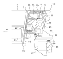
図1及び図2は、本発明に係るハイブリッド式船外機10を搭載した船舶もしくは舟艇の例を示している。この例では船舶は典型的には中小型とし、船体1の後部にトランサムボード2(船尾板)有するものとする。船外機10は図示のようにトランサムボード2を利用して搭載される。なお、以下で参照する各図の要所において、前方(船首側)を矢印Frにより、後方(船尾側)を矢印Rrによりそれぞれ示す。また、必要に応じて船体の左右方向(船体幅方向)をそれぞれ矢印L、矢印Rにより示す。
Hereinafter, preferred embodiments of a hybrid outboard motor according to the present invention will be described with reference to the drawings.
1 and 2 show an example of a ship or a boat equipped with a hybrid outboard motor 10 according to the present invention. In this example, the ship is typically small and medium, and has a transom board 2 (stern board) at the rear of the hull 1. The outboard motor 10 is mounted using the transom board 2 as shown. Note that, in the main points of the respective drawings referred to below, the front (the bow side) is indicated by an arrow Fr, and the rear (stern side) is indicated by an arrow Rr. Moreover, the left-right direction (hull width direction) of a hull is shown by the arrow L and the arrow R, respectively as needed.

ここで先ず、本実施形態に係る船体1において、図3のように船体1の船底3の上方には船床4が敷設され、この船床4にはトランサムボード2の前方位置にて段部4aが設けられている。なお、船舶としてこの図示例のものに限定されず、その他トランサムボードの後側に船外機搭載用のブラケット等を具備した船体もあり、つまり船体の船尾に船尾板又はこれに相当する部位もしくは部材を有するタイプのものに対して、本発明のハイブリッド式船外機10は有効に適用可能である。   First, in the hull 1 according to the present embodiment, a ship floor 4 is laid above the ship bottom 3 of the hull 1 as shown in FIG. 3, and a step portion is provided on the ship floor 4 at a position in front of the transom board 2. 4a is provided. In addition, the ship is not limited to the illustrated example, and there is also a hull having a bracket for mounting an outboard motor on the rear side of the transom board, that is, a stern plate or a part corresponding to the stern plate on the stern of the hull. The hybrid outboard motor 10 of the present invention can be effectively applied to a type having members.

ケーシング
ハイブリッド式船外機10はケーシング11を有し、図4のようにケーシング11内部に後述するパワーユニットを収容すると共に、ケーシング11の外部にスクリュー(プロペラ)を配置し、パワーユニットによってスクリューを回転駆動する。ケーシング11は船外機10の外観を構成する外装部材としても機能し、全体として一体感のある外観を呈している。
The casing hybrid outboard motor 10 has a casing 11 and houses a power unit, which will be described later, inside the casing 11 as shown in FIG. 4. A screw (propeller) is disposed outside the casing 11, and the screw is driven to rotate by the power unit. To do. The casing 11 also functions as an exterior member that configures the exterior of the outboard motor 10 and exhibits an exterior with a sense of unity as a whole.

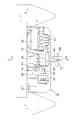
ケーシング11は図5をも参照して、船体1の船尾部(典型的にはトランサムボード2とする)と略同一の幅を有する筐体として構成される。この例ではケーシング11の基本的な形態は直方体とし、該直方体の長手方向が船体幅方向(以下、船幅方向と略称する)としている。ケーシング11の筐体は少なくとも、トランサムボード2に結合する前面部11aと、トランサムボード2の頂部2aと略同一の高さ又は適度に低い高さとした実質的に平坦な上面部11bとを有する。ケーシング11は更に船幅方向両端の側面部11cと、後述するようにスクリューが配設される後面部11dと、船尾部の船底3よりも適度に高く配置される底面部11eとを有し、これらの面によってその基本的形態が構成される。   The casing 11 is also configured as a housing having substantially the same width as the stern portion (typically, the transom board 2) of the hull 1 with reference to FIG. In this example, the basic form of the casing 11 is a rectangular parallelepiped, and the longitudinal direction of the rectangular parallelepiped is the hull width direction (hereinafter abbreviated as the ship width direction). The casing of the casing 11 has at least a front surface portion 11a coupled to the transom board 2 and a substantially flat upper surface portion 11b having substantially the same height as the top portion 2a of the transom board 2 or a moderately low height. The casing 11 further includes side surface portions 11c at both ends in the width direction of the ship, a rear surface portion 11d where screws are disposed as will be described later, and a bottom surface portion 11e that is disposed appropriately higher than the bottom 3 of the stern. These aspects constitute the basic form.

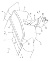
ケーシング11はまた、ケーシング本体12とその上部に開閉可能に取り付けられたカバー13とを含んでいる。ケーシング本体12の前面部11aの内面側には、ベース板14が一体的に結合する(図5(b)参照)。ベース板14はアルミニウム合金等で形成され、パワーユニット等を始めとする船外機10の構成部材を支持すると共に、船外機作動時に発生する荷重あるいは負荷等を支承する。なお、ケーシング11それ自体で所定の剛性を備えており、内部に収容される船外機構成部材を支持あるいは取り付けるために適宜利用可能である。   The casing 11 also includes a casing body 12 and a cover 13 attached to the upper portion of the casing body 12 so as to be openable and closable. A base plate 14 is integrally coupled to the inner surface side of the front surface portion 11a of the casing body 12 (see FIG. 5B). The base plate 14 is formed of an aluminum alloy or the like, supports the constituent members of the outboard motor 10 such as a power unit, and supports a load or a load generated when the outboard motor is operated. The casing 11 itself has a predetermined rigidity, and can be used as appropriate for supporting or mounting the outboard motor component housed inside.

また、ベース板14(ケーシング11の前面部11aを含む)には、船体1への取付穴15が設けられる。この例ではベース板14の左右両端部において、上下方向に列設された複数の上側取付穴15Aと単一の下側取付穴15Bが形成されており、これらの取付穴15A及び15Bに挿通させたボルト(図示せず)によってベース板14、従って船外機10全体を船体1に強固に固定することができる。なお、下側取付穴15Bは、上下方向に沿って形成された長穴であってよい。   The base plate 14 (including the front surface portion 11a of the casing 11) is provided with a mounting hole 15 for the hull 1. In this example, a plurality of upper mounting holes 15A and a single lower mounting hole 15B arranged in the vertical direction are formed at the left and right ends of the base plate 14, and are inserted through these mounting holes 15A and 15B. The base plate 14, and thus the outboard motor 10 as a whole, can be firmly fixed to the hull 1 by a bolt (not shown). The lower mounting hole 15B may be a long hole formed along the vertical direction.

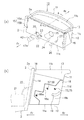
カバー13は上面部11bを構成するが、ケーシング本体12の前部上端付近にてヒンジ16を介して回動可能に結合する。図6のようにカバー13をヒンジ16のまわりに回動させて開成することで、ケーシング11内部が開放され、これにより露呈したケーシング11内部のパワーユニット等に自由にアクセス可能となる。カバー13を開けて内部の点検等を容易に行うことができ、この種の作業の利便性を向上することができる。ケーシング本体12とカバー13の閉合部もしくは合せ面にはシール17(図6参照)が敷設され、カバー13を閉めることでケーシング11の高い水密性が確保・保持される。   The cover 13 constitutes the upper surface portion 11 b, but is coupled to be rotatable through a hinge 16 near the front upper end of the casing body 12. By rotating the cover 13 around the hinge 16 and opening it as shown in FIG. 6, the inside of the casing 11 is opened, and thus the exposed power unit and the like inside the casing 11 can be freely accessed. The cover 13 can be opened to easily check the inside, and the convenience of this type of work can be improved. A seal 17 (see FIG. 6) is laid on the closing portion or mating surface of the casing body 12 and the cover 13, and the casing 13 is closed to ensure and maintain the high water tightness of the casing 11.

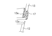
ここで、シール17は図6に示されるように、ケーシング本体12及びカバー13の合せ面に沿って全周に亘って敷設される。図7に示すようにカバー13の開口縁部、即ち閉合部13aに沿ってシール17としてのサイドシールが装着される。そして、カバー13が閉まった際にはケーシング本体12の閉合部12aとの間に挟着され、これによりケーシング11に対する高い水密性が得られる。   Here, as shown in FIG. 6, the seal 17 is laid over the entire circumference along the mating surfaces of the casing body 12 and the cover 13. As shown in FIG. 7, a side seal as a seal 17 is attached along the opening edge of the cover 13, that is, the closing portion 13a. And when the cover 13 is closed, it is pinched | interposed between the closure parts 12a of the casing main body 12, and, thereby, the high watertightness with respect to the casing 11 is acquired.

また、ケーシング11の上面部11b、即ちカバー13の上表面を平坦とすることにより、舟艇もしくはボートのデッキ延長として機能的及び意匠的に、船外機10が船体1から滑らかに連続するように一体化する。なお、カバー13の上表面には適度な大きさの凹凸を設け、これにより滑り止め効果を持たせることができる。その他、別体の滑り止めラバー等を添着してもよい。これにより、従来の船外機では不可能であった網の取込み、釣った魚の取込み、あるいはレスキューの際対象人員の取り込みが可能であるだけでなく、船尾を桟橋に近づけて、ボートへの乗り降りを船尾から行うことが可能になる。   Further, by flattening the upper surface portion 11 b of the casing 11, that is, the upper surface of the cover 13, the outboard motor 10 is smoothly and continuously connected from the hull 1 functionally and designally as an extension of a boat or a boat deck. Integrate. In addition, the upper surface of the cover 13 is provided with unevenness of an appropriate size, thereby providing an anti-slip effect. In addition, a separate non-slip rubber or the like may be attached. This makes it possible not only to capture nets, fish caught by fish, or rescue personnel during rescue, but also to get on and off the boat with the stern close to the pier. Can be performed from the stern.

更に、ケーシング11の後面側において、後面部11dから底面部11eへかけての領域において上面部11bよりも下方であって、船幅方向中央部には凹部18が設けられている。この凹部18には、後述する船舶の推進装置及びそのチルト・ステアリング機構等が配設される。凹部18は後面部11dから前方へ向けて形成されるが、図5(b)に示されるように前面部11aまでは到達せず、即ち前面部11aの手前にその前壁18aが形成される。この前壁18aは段状又は凹凸状に折曲しており、チルト機構あるいはその周辺機器や部材等の配置及び作動空間等を確保するようにしている。   Further, on the rear surface side of the casing 11, a recess 18 is provided at the center in the ship width direction, which is lower than the upper surface portion 11 b in a region from the rear surface portion 11 d to the bottom surface portion 11 e. The recess 18 is provided with a marine vessel propulsion device and its tilt / steering mechanism, which will be described later. The concave portion 18 is formed forward from the rear surface portion 11d, but does not reach the front surface portion 11a as shown in FIG. 5B, that is, the front wall 18a is formed in front of the front surface portion 11a. . The front wall 18a is bent in a stepped shape or an uneven shape so as to secure the arrangement and operating space of the tilt mechanism or its peripheral devices and members.

凹部18の左右両側壁18bの後端には、後面部11dとの間で面取18cが形成されている。この面取18cは後述するように、ステアリング機構によって推進機が左右に回動する際、部材相互の干渉を防止するものである。また、側壁18bには、後述するスイベルブラケットの横方向スラストを支えるための案内部もしくはガイド19が設けられている。なお、ケーシング11の底面部11cは、少なくとも船底3よりも適度に高く設定される。   A chamfer 18c is formed at the rear end of the left and right side walls 18b of the recess 18 with the rear surface portion 11d. As will be described later, the chamfer 18c prevents the members from interfering with each other when the propulsion unit is rotated left and right by the steering mechanism. The side wall 18b is provided with a guide portion or a guide 19 for supporting a lateral thrust of a swivel bracket described later. The bottom surface portion 11c of the casing 11 is set to be appropriately higher than at least the ship bottom 3.

更に、図5(a)に示すようにケーシング11の前面部11a及びベース板14とトランサムボード2との間で穴を共あけするかたちで、複数の貫通孔が形成されている。即ち、後述するようにエンジンに燃焼用空気を供給するための吸気管42を挿通させるための貫通孔20、燃料タンク21からエンジンに燃料を供給するための燃料パイプ22を挿通させるための貫通孔23、ケーシング11内を換気するための換気空気用筒体24を通すための貫通孔25が形成される。更に、ケーシング11内の装置もしくは機器類又は部材と船体1側の操縦装置との間を、電気的(制御信号等を含む)あるいは機械的に接続するコード又はケーブル類26を挿通させるための貫通孔27が形成される。なお、これらの貫通孔には実装時に水密保持手段(シール等)が施される。   Further, as shown in FIG. 5A, a plurality of through holes are formed in the form of making a hole between the front surface portion 11 a of the casing 11 and the base plate 14 and the transom board 2. That is, as will be described later, a through hole 20 for inserting an intake pipe 42 for supplying combustion air to the engine and a through hole for inserting a fuel pipe 22 for supplying fuel from the fuel tank 21 to the engine. 23, a through hole 25 is formed through which a cylinder 24 for ventilation air for ventilating the inside of the casing 11 is passed. Furthermore, a cord or cable 26 for electrically (including a control signal) or mechanical connection between the device or equipment or member in the casing 11 and the control device on the hull 1 side is inserted therethrough. A hole 27 is formed. These through holes are provided with watertight holding means (seal etc.) at the time of mounting.

パワーユニットの全体構成
次に、ケーシング11内に収容されるパワーユニットについて説明する。ここで、図8はパワーユニットの後面正面図、図9は前面正面図、図10は左側面図、図11は上面図、図12は底面図、図13は前面正面図、図14は後面正面図、図15は上面図、図16は底面図である。これらの図をも参照しつつ、各部の構成につき更に詳細に説明する。
Overall structure of the power unit will now be described a power unit housed in the casing 11. 8 is a rear front view of the power unit, FIG. 9 is a front front view, FIG. 10 is a left side view, FIG. 11 is a top view, FIG. 12 is a bottom view, FIG. 13 is a front front view, and FIG. 15 is a top view, and FIG. 16 is a bottom view. The configuration of each part will be described in more detail with reference to these drawings.

本発明のハイブリッド式船外機10はそのパワーユニットとして、内燃機関と電動モータを主動力とし、これらをそれぞれ独立して又は双方同時に作動させて推進機を駆動する。この実施形態では電動モータは発電機能を兼備し、即ち電動モータとして動力を発生すると共に発電した電力をバッテリに供給するジェネレータとして機能する(以下、モータジェネレータと称する)。このモータジェネレータは永久磁石式交流同期モータ型であり、電動モータとして使用する場合、バッテリからインバータを介して供給される三相交流を用いて、永久磁石を取り付けたロータを三相交流に同期させて回転させることにより、小型でありながら強力なトルクを発生する。一方、発電機として使用する場合、内燃機関の動力によりロータを回転させることで三相交流を発生させ、この三相交流に基づきインバータを介してバッテリを充電する。モータジェネレータの駆動用電気エネルギー貯蔵装置として、一般的にはバッテリもしくは電池であるが、キャパシタ等を用いることも可能である。   The hybrid outboard motor 10 according to the present invention has, as its power unit, an internal combustion engine and an electric motor as main powers, and these are operated independently or simultaneously to drive the propulsion unit. In this embodiment, the electric motor also has a power generation function, that is, functions as a generator that generates power as an electric motor and supplies the generated power to the battery (hereinafter referred to as a motor generator). This motor generator is a permanent magnet AC synchronous motor type. When used as an electric motor, the rotor with a permanent magnet is synchronized with the three-phase AC using the three-phase AC supplied from the battery via the inverter. By rotating it, it generates a powerful torque despite its small size. On the other hand, when used as a generator, the rotor is rotated by the power of the internal combustion engine to generate a three-phase alternating current, and the battery is charged via the inverter based on the three-phase alternating current. The electric energy storage device for driving the motor generator is generally a battery or a battery, but a capacitor or the like can also be used.

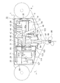
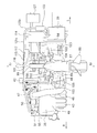
パワーユニットを構成する主要部材即ち内燃機関、モータジェネレータ、インバータ及びバッテリ等の重量物は、ケーシング11内にコンパクト且つバランス良く収容される。先ず図6及び図8等に示されるように、その筐体の長手方向が船幅方向としたケーシング11の左右一方側、この例では右側に内燃機関、即ちエンジン28が配置される。また、ケーシング11の左右他方側である左側にはモータジェネレータ29及びその前斜め上方のバッテリ30(高電圧用)が配置される。即ちパワーユニットの主要構成部材であるエンジン28と、モータジェネレータ29及びバッテリ30とをケーシング11内で左右に並置する。インバータ31はこの例では幅方向略中央に配置されるが、エンジン28と反対側、即ち左側寄りに配置してもよく、いずれの場合もケーシング11の左右間で重量バランスよく配置するものとする。   Major members constituting the power unit, that is, heavy objects such as an internal combustion engine, a motor generator, an inverter, and a battery are accommodated in the casing 11 in a compact and well-balanced manner. First, as shown in FIG. 6 and FIG. 8 and the like, an internal combustion engine, that is, an engine 28 is arranged on one side of the casing 11 whose longitudinal direction is the ship width direction, in this example, on the right side. In addition, a motor generator 29 and a battery 30 (for high voltage) that is obliquely above and in front of the motor generator 29 are arranged on the left side that is the left and right side of the casing 11. That is, the engine 28 which is a main component of the power unit, the motor generator 29 and the battery 30 are juxtaposed side by side in the casing 11. In this example, the inverter 31 is disposed substantially at the center in the width direction. However, the inverter 31 may be disposed on the side opposite to the engine 28, that is, on the left side. In any case, the inverter 31 is disposed between the left and right sides of the casing 11 with a good weight balance. .

より具体的には、相互に連結されるエンジン28のクランク軸とモータジェネレータ29の入力軸とをそれぞれ船幅方向に沿うように、且つ水平に配置する。また、モータジェネレータ29の出力軸の延長上には後述するチルト軸を有し、船幅方向センタにて該チルト軸から推進機を垂架する。なお、これらの詳細については後述するものとする。   More specifically, the crankshaft of the engine 28 and the input shaft of the motor generator 29 that are connected to each other are arranged horizontally along the ship width direction. In addition, a tilt shaft, which will be described later, is provided on the extension of the output shaft of the motor generator 29, and a propulsion unit is suspended from the tilt shaft at the center in the ship width direction. These details will be described later.

パワーユニットの構成部材のうち、そのかなりの重量を占めるエンジン28とモータジェネレータ29及びバッテリ30とを、上記のようにケーシング11において略センタ振分けで水平配置する。かかる配置構造により、パワーユニットシステム全体の重心を船体1(トランサムボード2)側寄りに接近させ、これにより前後方向には張り出さない。同時に水平配置する、即ちクランク軸を鉛直方向としないことで上下方向にも、特に上方に張り出すことなく、これらの構成部材はケーシング11にコンパクトに収容される。このようにエンジン28とモータジェネレータ29間の動力伝達経路を水平に設定し、トランサムボード2に近接配置できるので、本システム全体の重心位置はトランサムボード2に近くなる。従って、船外機10を搭載した船体1の水上での姿勢が船尾下がりになるのを極力抑制し、また滑走に移行するのが極めて円滑で、しかも容易且つ的確である。   Among the constituent members of the power unit, the engine 28, the motor generator 29, and the battery 30 that occupy a considerable weight are horizontally arranged in the casing 11 with substantially center distribution as described above. With such an arrangement structure, the center of gravity of the entire power unit system is brought closer to the hull 1 (transom board 2) side, so that it does not protrude in the front-rear direction. These components are accommodated in the casing 11 in a compact manner without being overhanging in the vertical direction by arranging them horizontally at the same time. As described above, the power transmission path between the engine 28 and the motor generator 29 can be set horizontally and placed close to the transom board 2, so that the center of gravity of the entire system is close to the transom board 2. Accordingly, it is extremely smooth, easy and accurate to suppress the hull 1 mounted on the outboard motor 10 from being lowered on the stern as much as possible and to shift to sliding.

エンジン
内燃機関としては水冷式多気筒(この例では4気筒)直列4サイクルガソリンエンジンを使用する。なお、エンジンの気筒数等は必要に応じて適宜変更可能であり、この例に限定されるものではない。図17をも参照して、エンジン28の相互に一体的に結合するシリンダブロック32及びクランクケース33内において、各気筒のシリンダボア34内にピストン35が往復動自在に収容され、各ピストン35ともそれぞれコンロッド36を介してクランクシャフト37と連結する。クランクシャフト37は船幅方向(左右方向)に沿って配置され、その軸端に付設されたフライホイール38には、左方へ延出するエンジン出力軸39がクランクシャフト37と同心に取り付けられる。
As the engine internal combustion engine, a water-cooled multi-cylinder (4 cylinders in this example) in-line 4-cycle gasoline engine is used. Note that the number of cylinders of the engine can be appropriately changed as necessary, and is not limited to this example. Referring also to FIG. 17, in a cylinder block 32 and a crankcase 33 that are integrally coupled to each other of the engine 28, pistons 35 are reciprocally accommodated in cylinder bores 34 of the respective cylinders. The crankshaft 37 is connected via a connecting rod 36. The crankshaft 37 is disposed along the ship width direction (left-right direction), and an engine output shaft 39 extending leftward is attached concentrically with the crankshaft 37 to a flywheel 38 attached to the shaft end.

エンジン28の各シリンダボア34内で往復動するピストン35の上部には、点火プラグ40が栓着すると共に、シリンダヘッド41内に吸気バルブ及び排気バルブ(共に図示せず)を開閉駆動する動弁装置が収容される。本実施形態ではシリンダヘッド41において後方側に吸気バルブが、また前方側に排気バルブがそれぞれ配置される。   A spark plug 40 is plugged onto the piston 35 that reciprocates within each cylinder bore 34 of the engine 28, and a valve operating device that opens and closes an intake valve and an exhaust valve (both not shown) in the cylinder head 41. Is housed. In the present embodiment, the cylinder head 41 is provided with an intake valve on the rear side and an exhaust valve on the front side.

吸気側において、図9等に示すように吸気管42がケーシング11前部の船体1側まで延出し(図5(a)をも参照のこと)、その先端の空気取込み口42aから空気を取り込むようになっている。空気取込み口42aは、船体1において波、しぶき及び雨等に曝されることがない部屋もしくはスペースに設置される。図8及び図14に示されるように単一の吸気管42は各気筒の吸気マニホールド43に分岐するが、この分岐部位にスロットルボディ44が配置されている。スロットルボディ44において各吸気マニホールド43に対して、適正混合比となるように形成された混合気が供給される。   On the intake side, as shown in FIG. 9 and the like, the intake pipe 42 extends to the hull 1 side of the front portion of the casing 11 (see also FIG. 5A), and takes in air from the air intake port 42a at the tip thereof. It is like that. The air intake 42a is installed in a room or space that is not exposed to waves, splashes, rain, or the like in the hull 1. As shown in FIGS. 8 and 14, the single intake pipe 42 branches to the intake manifold 43 of each cylinder, and the throttle body 44 is disposed at this branching portion. In the throttle body 44, an air-fuel mixture formed to have an appropriate mixing ratio is supplied to each intake manifold 43.

また、排気側において、図9及び図13等に示されるように各気筒の排気マニホールド(及びそのカバー)45が下方へ延出して互いに集合し、その後単一の排気管46に接続される。この集合部位には触媒装置47が設けられており、触媒装置47によって清浄化した排気を排気管46へと排出する。図8及び図14等を参照して、排気管46は後述するオイルパン49の下側に入り込んでエンジン28の後側へ延出し、再び上方へ引き回されて後、排気案内管48に接続される。なお、排気管46をこのように引き回す際、例えばケーシング11やシリンダブロック32の適所を利用して、支持ブラケット等を取り付け、この支持ブラケットを介して排気管46を支持することができる。また、排気管46の途中適所にマフラ(消音器)を設けることも可能である。排気は更に排気管46から、後述する排気案内管48及び排気通路等を通って、船外機10の外部へ排気されるようになっている。   On the exhaust side, as shown in FIGS. 9 and 13, etc., the exhaust manifold (and its cover) 45 of each cylinder extends downward and gathers together, and then is connected to a single exhaust pipe 46. A catalyst device 47 is provided at this gathering site, and the exhaust gas purified by the catalyst device 47 is discharged to the exhaust pipe 46. Referring to FIGS. 8 and 14, etc., the exhaust pipe 46 enters the lower side of an oil pan 49 to be described later, extends to the rear side of the engine 28, is routed upward again, and then connected to the exhaust guide pipe 48. Is done. When the exhaust pipe 46 is routed in this manner, for example, a support bracket or the like can be attached using the appropriate position of the casing 11 or the cylinder block 32 and the exhaust pipe 46 can be supported via the support bracket. It is also possible to provide a muffler (silencer) at an appropriate position in the middle of the exhaust pipe 46. Further, the exhaust gas is exhausted from the exhaust pipe 46 to the outside of the outboard motor 10 through an exhaust guide pipe 48 and an exhaust passage which will be described later.

エンジン28の下部には潤滑オイル用オイルパン49が配置されており、エンジン28の各部を潤滑した潤滑オイルがオイルパン49に回収される。オイルパン49に回収されたオイルは、シリンダブロック32の前側に取り付けられたオイルフィルタ50(図12、図13及び図16参照)を経て再びエンジン28の各部へと給送される。なお、潤滑オイルを循環させるためのオイルポンプが内蔵されている。   An oil pan 49 for lubricating oil is disposed below the engine 28, and the lubricating oil that has lubricated each part of the engine 28 is collected in the oil pan 49. The oil collected in the oil pan 49 is fed again to each part of the engine 28 through an oil filter 50 (see FIGS. 12, 13, and 16) attached to the front side of the cylinder block 32. An oil pump for circulating the lubricating oil is incorporated.

エンジン28の所要部位(シリンダブロック32及びシリンダヘッド41等)には、冷却液が循環流通するウォータジャケットが設けられている。この例では図12及び図13等に示されるようにシリンダブロック32の前側適所に配設され、クランクシャフト37の回転を動力源として作動する冷却液ポンプ51を有する。クランクシャフト37のフライホイール38とは反対側の軸端にはドライブプーリ52が取り付けられ、一方、冷却液ポンプ51の回転軸にはドリブンプーリ53が取り付けられる。両プーリ52,53間にはガイドプーリ54を介して、例えばタイミングベルト55が巻回され、これによりクランクシャフト37の回転で冷却液ポンプ51を駆動し、冷却液を所定流路に沿って循環させるようになっている。   A required portion of the engine 28 (cylinder block 32, cylinder head 41, etc.) is provided with a water jacket through which the coolant circulates. In this example, as shown in FIG. 12 and FIG. 13 and the like, a coolant pump 51 is provided at an appropriate position on the front side of the cylinder block 32 and operates using the rotation of the crankshaft 37 as a power source. A drive pulley 52 is attached to the shaft end of the crankshaft 37 opposite to the flywheel 38, while a driven pulley 53 is attached to the rotating shaft of the coolant pump 51. For example, a timing belt 55 is wound between the pulleys 52 and 53 via a guide pulley 54, whereby the coolant pump 51 is driven by the rotation of the crankshaft 37, and the coolant is circulated along a predetermined flow path. It is supposed to let you.

上記の場合、冷却液ポンプ51に対して、後述する熱交換器から冷却された冷却液が供給される。エンジン28を冷却するために使用された冷却液は熱交換器へ戻り、冷却後再び冷却液ポンプ51に供給されるようになっている。   In the above case, the coolant cooled from the heat exchanger described later is supplied to the coolant pump 51. The coolant used for cooling the engine 28 returns to the heat exchanger, and is supplied to the coolant pump 51 again after cooling.

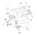
エンジン28は支持ブラケットもしくはマウントによって、ケーシング11内の所定位置に支持される。図18A〜図18D等に示されるようにシリンダブロック32あるいはシリンダヘッド41の所定部位等を、複数のマウント56A〜56Dによって支持する。各マウント56A,56B,56C,56Dはケーシング11の適所に直接又は間接的に取り付けることができる。あるいはベース板14を利用して取り付けることもでき、又はベース板14に支持されるフレーム構造部材(図示せず)に取り付けることも可能である。また、マウント56A〜56Dの設定部位や数量等は、ケーシング11内のスペースあるいはエンジン28に対する支持強度等との関係で適宜選択可能であるが、いずれの場合もエンジン28の高い支持剛性を確保し、且つエンジン28をバランスよく取付支持するものとする。   The engine 28 is supported at a predetermined position in the casing 11 by a support bracket or a mount. As shown in FIGS. 18A to 18D and the like, a predetermined portion or the like of the cylinder block 32 or the cylinder head 41 is supported by a plurality of mounts 56A to 56D. Each mount 56A, 56B, 56C, 56D can be directly or indirectly attached to a proper position of the casing 11. Alternatively, it can be attached using the base plate 14 or can be attached to a frame structure member (not shown) supported by the base plate 14. Further, the set parts, the quantity, and the like of the mounts 56A to 56D can be appropriately selected in relation to the space in the casing 11 or the support strength for the engine 28. In any case, the high support rigidity of the engine 28 is ensured. The engine 28 is attached and supported in a balanced manner.

モータジェネレータ
ケーシング11内で左右に並置されるエンジン28側とモータジェネレータ29側は、図13あるいは図17等のように、ユニバーサルジョイント57を介して相互に連結される。この場合、モータジェネレータ29には減速機58(初段)が一体的に結合しており、両者はユニットとして一体化している。具体的には減速機58を介して、ユニバーサルジョイント57とモータジェネレータ29とが連結される。ユニバーサルジョイント57の一端側(右側)は、図17に示されるようにエンジン出力軸39と連結し、他端側(左側)は減速機58の入力軸59と連結する。基本的にはクランクシャフト37、エンジン出力軸39、ユニバーサルジョイント57及び減速機58の入力軸59は実質的に同一軸線上に沿って、即ち船幅方向に配置される。
The engine 28 side and the motor generator 29 side juxtaposed side by side in the motor generator casing 11 are connected to each other via a universal joint 57 as shown in FIG. In this case, a reduction gear 58 (first stage) is integrally coupled to the motor generator 29, and both are integrated as a unit. Specifically, the universal joint 57 and the motor generator 29 are connected via the speed reducer 58. As shown in FIG. 17, one end side (right side) of the universal joint 57 is connected to the engine output shaft 39, and the other end side (left side) is connected to the input shaft 59 of the speed reducer 58. Basically, the crankshaft 37, the engine output shaft 39, the universal joint 57, and the input shaft 59 of the speed reducer 58 are arranged substantially along the same axis, that is, in the ship width direction.

ここで、ケーシング11の船幅方向中央部において凹部18に対応して、図12等に示されるように底面視(もしくは上面視)で「コ」字状の主ブラケット60が配置される(なお、図12においてはハッチングにより図示されている)。主ブラケット60はコ字の中央辺部で、ボルト等によりベース板14に固定支持され、該中央辺部の両側部がベース板14から後方へ延出して、凹部18(の側壁18b)を左右両側から挟み込むように配置される。また、主ブラケット60の左側近には「L」字状もしくは鉤型のモータブラケット61が配置される。このモータブラケット61の取付方法としては、例えばそのL字の底辺部にてベース板14に固定することができる。このように支持されるモータブラケット61は、ベース板14から後方へ延出し(図17等参照)、モータジェネレータ29と一体結合する減速機58を支持する。なお、ユニバーサルジョイント57はケーシング11の凹部18の内領域に配置され、即ちケーシング11の外部側に配置される。   Here, in the center portion of the casing 11 in the ship width direction, a “U” -shaped main bracket 60 is disposed in a bottom view (or a top view) as shown in FIG. In FIG. 12, this is indicated by hatching). The main bracket 60 is a U-shaped central side, and is fixedly supported on the base plate 14 with bolts or the like. Both side portions of the central side extend rearward from the base plate 14, and the concave portion 18 (side wall 18 b) is left and right. It is arranged so as to be sandwiched from both sides. Further, an “L” -shaped or bowl-shaped motor bracket 61 is disposed near the left side of the main bracket 60. As a mounting method of the motor bracket 61, for example, it can be fixed to the base plate 14 at the bottom of the L shape. The motor bracket 61 supported in this manner extends rearward from the base plate 14 (see FIG. 17 and the like), and supports a reduction gear 58 that is integrally coupled to the motor generator 29. The universal joint 57 is disposed in the inner region of the recess 18 of the casing 11, that is, disposed outside the casing 11.

図19に示されるように主ブラケット60(及び凹部18の側壁18b)には、エンジン出力軸39を挿通させるための孔60a、及び減速機58の入力軸59を挿通させるための孔60bが穿設されている。このうち一方の孔60aは、エンジン出力軸39よりも大径に形成され、両者の間に形成される隙間に対して水密を保持するためにブーツ62が装着される。なお、他方の孔60bについては、シールもしくはパッキン63が装着される。   As shown in FIG. 19, the main bracket 60 (and the side wall 18 b of the recess 18) has a hole 60 a for inserting the engine output shaft 39 and a hole 60 b for inserting the input shaft 59 of the speed reducer 58. It is installed. One of the holes 60a is formed to have a diameter larger than that of the engine output shaft 39, and a boot 62 is mounted to maintain watertightness with respect to a gap formed between the two holes 60a. A seal or packing 63 is attached to the other hole 60b.

前述のようにエンジン28はマウント56A〜56Dを介して取り付けられ、またモータジェネレータ29はマウント(モータブラケット61)を介して取り付けられる。エンジン28はその作動中、トルク反力、往復運動部や回転運動部の慣性力の不釣合い等により、その軸心であるクランクシャフト37、従ってエンジン出力軸39がエンジン28の作動状況に応じて位置ずれすることがある。また、モータジェネレータ29についても、トルク反力等に起因するが、作動状況に応じてその軸心が位置ずれすることがある。このような場合、エンジン28とモータジェネレータ29(具体的には減速機58の入力軸59)とをユニバーサルジョイント57を介して連結することで、相互間に生じる軸心のずれを吸収して、円滑なトルク伝達を保証することができる。   As described above, the engine 28 is attached via the mounts 56A to 56D, and the motor generator 29 is attached via the mount (motor bracket 61). During the operation of the engine 28, the torque shaft, the unbalance of the inertial force of the reciprocating motion part and the rotational motion part, etc. cause the crankshaft 37, and hence the engine output shaft 39, to be in accordance with the operating condition of the engine 28. Misalignment may occur. Further, the motor generator 29 is also caused by a torque reaction force or the like, but the axis of the motor generator 29 may be displaced depending on the operation state. In such a case, by connecting the engine 28 and the motor generator 29 (specifically, the input shaft 59 of the speed reducer 58) via the universal joint 57, the misalignment of the shaft center that occurs between them is absorbed, Smooth torque transmission can be guaranteed.

減速機
次に、減速機58は図19等に示されるようにそのケーシング64内に、入力軸59と接続可能なドライブギア65と、このドライブギア65と噛合するドリブンギア66とがそれぞれ回転自在に軸支されている。これらのドライブギア65及びドリブンギア66は平歯車等であってよく、両者間の変速比は、エンジン28の作動上最も効率がよい回転数とモータジェネレータ29の作動上最も効率がよい回転数とが両立するように設定される。
Reducer Next, as shown in FIG. 19 and the like, the reducer 58 includes a drive gear 65 that can be connected to the input shaft 59 and a driven gear 66 that meshes with the drive gear 65 in the casing 64, respectively. Is pivotally supported. The drive gear 65 and the driven gear 66 may be spur gears, and the speed ratio between them is the most efficient rotational speed for the operation of the engine 28 and the most efficient rotational speed for the operation of the motor generator 29. Are set to be compatible.

ドライブギア65の回転軸65aと入力軸59との間には第1クラッチ67が介装される。この第1クラッチ67は所謂、電磁クラッチ等により構成され、ハイブリッドコントロールユニットによって所定のタイミングで適宜、エンジン28側とモータジェネレータ29側の間の動力伝達経路を接続・切離するように制御される。   A first clutch 67 is interposed between the rotation shaft 65 a of the drive gear 65 and the input shaft 59. The first clutch 67 is constituted by a so-called electromagnetic clutch or the like, and is controlled by a hybrid control unit so as to connect / disconnect a power transmission path between the engine 28 side and the motor generator 29 side as appropriate at a predetermined timing. .

バッテリ/インバータ
モータジェネレータ29は、前述したように電動モータ機能と発電機能とを兼備している。モータジェネレータ29の周辺機器としてのバッテリ30は、図8あるいは図10等に示されるようにベース板14に固定支持されて後方へ延出する支持ブラケット68によって水平に支持される。バッテリ30は支持ブラケット68を介して、モータジェネレータ29の前斜め上方位置に支持されるが、ケーシング11内で前面部11a側に配置される。バッテリ30もかなりの重量物であり、このように前面部11a寄りに配置することで、船外機10の重心を船体1側に近づけることができる。
The battery / inverter motor generator 29 has both the electric motor function and the power generation function as described above. The battery 30 as a peripheral device of the motor generator 29 is horizontally supported by a support bracket 68 that is fixedly supported by the base plate 14 and extends rearward as shown in FIG. The battery 30 is supported at an obliquely upper front position of the motor generator 29 via the support bracket 68, but is disposed on the front surface portion 11 a side in the casing 11. The battery 30 is also a heavy object, and the center of gravity of the outboard motor 10 can be brought closer to the hull 1 side by being arranged closer to the front surface portion 11a.

また、インバータ31は図8等に示されるように、主ブラケット60の上部に配置された支持ブラケット69によって支持される。この例ではケーシング11の船幅方向略中央部又は左側寄りであって、図10等に示されるように側面視ではモータジェネレータ29の上方位置に配置される。また、バッテリ30よりも適度に高い位置であって、ケーシング11のカバー13直近に配置される。   Further, as shown in FIG. 8 and the like, the inverter 31 is supported by a support bracket 69 disposed on the upper part of the main bracket 60. In this example, the casing 11 is disposed approximately at the center or the left side in the ship width direction, and is disposed at a position above the motor generator 29 in a side view as shown in FIG. Moreover, it is a position moderately higher than the battery 30 and is disposed in the vicinity of the cover 13 of the casing 11.

モータジェネレータ29は前述したように電動モータと発電機の機能を有しており、そのためモータジェネレータ29及びインバータ31間は三相交流用電気配線70を介して接続され、バッテリ30及びインバータ31間は直流用電気配線71を介して接続される(図13及び図14等参照)。モータジェネレータ29を電動モータとして使用する場合、バッテリ30の電力はインバータ31を介して交流電流として、モータジェネレータ29に供給され、一方、発電機として使用する場合はモータジェネレータ29の発生電力はインバータ31を介して直流電流として、バッテリ30に供給される。なお、これらの切替制御は、ハイブリッドコントロールユニットによって行われる。   As described above, the motor generator 29 has the functions of an electric motor and a generator. Therefore, the motor generator 29 and the inverter 31 are connected via the three-phase AC electric wiring 70, and the battery 30 and the inverter 31 are not connected. They are connected via the DC electric wiring 71 (see FIG. 13 and FIG. 14). When the motor generator 29 is used as an electric motor, the electric power of the battery 30 is supplied to the motor generator 29 as an alternating current through the inverter 31. On the other hand, when the motor generator 29 is used as a generator, the electric power generated by the motor generator 29 is supplied to the inverter 31. Is supplied to the battery 30 as a direct current. Note that these switching controls are performed by the hybrid control unit.

モータジェネレータ29のロータ軸72は図19に示されるように、ドリブンギア66と同心に結合し、このドリブンギア66と一体化した回転軸66aが入力軸59の後方側で、これと平行にエンジン28側へ延出する。この回転軸66aの延長上にチルトシャフト73がチルト軸受74(ニードルベアリング等でよい)を介して、主ブラケット60によって回転可能に横架・支持される。チルトシャフト73はその基本形態として円筒状の中空構造を有し、ユニバーサルジョイント57の後方側にてこれと平行に、凹部18の内幅に亘って架け渡されるかたちで配置される。チルトシャフト73の一端側(右側)は閉塞し、他端側(左側)にはモータジェネレータ出力軸75が内挿される。モータジェネレータ出力軸75はチルトシャフト73内で、軸受76を介して回転可能に支持される。チルトシャフト73の他端にはモータジェネレータ出力軸75との間にシール77が挿着される。   As shown in FIG. 19, the rotor shaft 72 of the motor generator 29 is concentrically coupled with the driven gear 66, and a rotating shaft 66 a integrated with the driven gear 66 is on the rear side of the input shaft 59 and parallel to the engine. Extend to the 28th side. A tilt shaft 73 is horizontally mounted and supported by the main bracket 60 via a tilt bearing 74 (may be a needle bearing or the like) on the extension of the rotating shaft 66a. The tilt shaft 73 has a cylindrical hollow structure as its basic form, and is arranged on the rear side of the universal joint 57 so as to be bridged over the inner width of the recess 18. One end side (right side) of the tilt shaft 73 is closed, and a motor generator output shaft 75 is inserted on the other end side (left side). The motor generator output shaft 75 is rotatably supported in the tilt shaft 73 via a bearing 76. A seal 77 is inserted between the other end of the tilt shaft 73 and the motor generator output shaft 75.

ドリブンギア66の回転軸66aとモータジェネレータ出力軸75との間には、図19に示されるように第2クラッチ78が介装される。この第2クラッチ78は電磁クラッチ等により構成され、ハイブリッドコントロールユニットによって所定のタイミングで適宜、モータジェネレータ29側とモータジェネレータ出力軸75側、ひいては推進機側との間の動力伝達経路を接続・切離するように制御される。なお、第2クラッチ78の作動制御は、ハイブリッドコントロールユニットによって行われる。   A second clutch 78 is interposed between the rotating shaft 66a of the driven gear 66 and the motor generator output shaft 75 as shown in FIG. The second clutch 78 is constituted by an electromagnetic clutch or the like, and the power transmission path between the motor generator 29 side and the motor generator output shaft 75 side, and consequently the propulsion device side is appropriately connected / disconnected at a predetermined timing by the hybrid control unit. Controlled to separate. The operation control of the second clutch 78 is performed by the hybrid control unit.

チルトシャフト73はそれ自体でギアケースとなり、即ちその内部にベベルギア79及びピニオン80によって構成される中間減速機81が配置される。モータジェネレータ出力軸75の先端部にはピニオン80が取り付けられる。また、水平配置されたモータジェネレータ出力軸75と直交して下方へ延出するドライブシャフト82の上端部には、ベベルギア79が取り付けられる。このようにモータジェネレータ出力軸75とドライブシャフト82の間に中間減速機81を設置することで、モータジェネレータ29の効率のよい回転数と推進機のプロペラの効率のよい回転数とを一致させている。   The tilt shaft 73 itself becomes a gear case, that is, an intermediate speed reducer 81 configured by a bevel gear 79 and a pinion 80 is disposed therein. A pinion 80 is attached to the tip of the motor generator output shaft 75. A bevel gear 79 is attached to an upper end portion of a drive shaft 82 that extends downward perpendicularly to the motor generator output shaft 75 that is horizontally disposed. By installing the intermediate speed reducer 81 between the motor generator output shaft 75 and the drive shaft 82 in this way, the efficient rotational speed of the motor generator 29 and the efficient rotational speed of the propeller of the propulsion device are matched. Yes.

図19〜図21に示されるようにケーシング11の凹部18の船幅方向中央部でチルトシャフト73から下方へ延出するドライブシャフト82の周囲には、ドライブシャフトケース83が配置される。このドライブシャフトケース83の前側にはスイベルブラケット84が配置され、これらチルトシャフト73、ドライブシャフトケース83及びスイベルブラケット84は、相互に一体的に結合する。スイベルブラケット84はその基本的形態において、凹部18の内幅と略等しい船幅方向に広がりを持つ概略板状を呈し、外力等の負荷荷重に対して高い剛性強度を備えている。スイベルブラケット84の下端には後方へ延出するロアステアリングブラケット85が固着する。   As shown in FIGS. 19 to 21, a drive shaft case 83 is disposed around a drive shaft 82 that extends downward from the tilt shaft 73 at the center in the ship width direction of the recess 18 of the casing 11. A swivel bracket 84 is disposed on the front side of the drive shaft case 83, and the tilt shaft 73, the drive shaft case 83, and the swivel bracket 84 are integrally coupled to each other. In its basic form, the swivel bracket 84 has a substantially plate shape extending in the ship width direction substantially equal to the inner width of the recess 18 and has a high rigidity and strength against a load load such as an external force. A lower steering bracket 85 extending rearward is fixed to the lower end of the swivel bracket 84.

上述のようにモータジェネレータ出力軸75はチルト軸と一致しおり、チルト軸から下方に垂架されるドライブシャフト82や後述する推進機は、このチルト軸を中心に上下方向に回動可能、即ちチルティング作動する。これにより船速及び推進力に応じた最適推進角度で運転が可能であり、一方、最大チルトアップ姿勢では水上係留において、推進機まわりを水面から離してドライ状態とすることができる。   As described above, the motor generator output shaft 75 coincides with the tilt axis, and the drive shaft 82 and the propulsion unit, which will be described later, can be rotated up and down around the tilt axis. Tilt operation. As a result, it is possible to operate at an optimum propulsion angle corresponding to the ship speed and propulsive force, while in the maximum tilt-up position, the propulsion unit can be kept away from the water surface in a dry state in mooring on the water.

なお、チルトシャフト73の周囲(の一部)にはエンジン28で発生した燃料ガスを排気するための排気通路が形成され、この排気通路は更にドライブシャフトケース83内部を経由して形成されるが、これについては後述するものとする。   An exhaust passage for exhausting the fuel gas generated in the engine 28 is formed around (a part of) the tilt shaft 73, and this exhaust passage is further formed through the inside of the drive shaft case 83. This will be described later.

推進機
図20等に示されるようにドライブシャフトケース83の下方には、プロペラを有する推進機86が配置される。推進機86は、プロペラ駆動用のギアを内蔵するギアケース87を含み、全体としてフィン状を呈する。ギアケース87の後端部にはプロペラ88が装架される。ドライブシャフト82はドライブシャフトケース83内を通って更に下方へ延出し、ギアケース87内まで延設される。ここで、ギアケース87は、ドライブシャフトケース83の周囲に設けた軸受部89及びこの軸受部89に結合するドライブシャフトハウジング90を介して、スイベルブラケット84のロアステアリングブラケット85によって回動可能に支持される。
As shown in FIG. 20 and the like, a propulsion device 86 having a propeller is disposed below the drive shaft case 83. The propulsion device 86 includes a gear case 87 in which a propeller driving gear is incorporated, and has a fin shape as a whole. A propeller 88 is mounted on the rear end portion of the gear case 87. The drive shaft 82 extends further downward through the drive shaft case 83 and extends into the gear case 87. Here, the gear case 87 is rotatably supported by the lower steering bracket 85 of the swivel bracket 84 via a bearing portion 89 provided around the drive shaft case 83 and a drive shaft housing 90 coupled to the bearing portion 89. Is done.

ドライブシャフト82は図22にも示されるように、ギアケース87内で軸受91によって支持される。ギアケース87の内部にベベルギア92及びピニオン93によって構成される最終減速機94が配置される。ドライブシャフト82の下端部にはピニオン93が取り付けられ、垂直配置されたドライブシャフト82と直交して水平後方へ延出するプロペラシャフト95の前端部にはベベルギア92が取り付けられる。プロペラシャフト95は、その前端部及び後端部付近でそれぞれ軸受96,97によって回転可能に支持され、後端部にプロペラ88が取り付けられている。軸受96,97は、ベアリングハウジング98内に配設される。これによりドライブシャフト82の回転で、最終減速機94を介してプロペラシャフト95、従ってプロペラ88を回転駆動することができる。   The drive shaft 82 is supported by a bearing 91 in the gear case 87 as shown in FIG. A final reduction gear 94 constituted by a bevel gear 92 and a pinion 93 is disposed inside the gear case 87. A pinion 93 is attached to the lower end portion of the drive shaft 82, and a bevel gear 92 is attached to the front end portion of the propeller shaft 95 that extends orthogonally to the vertically arranged drive shaft 82. The propeller shaft 95 is rotatably supported by bearings 96 and 97 near the front end portion and the rear end portion thereof, and a propeller 88 is attached to the rear end portion. The bearings 96 and 97 are disposed in the bearing housing 98. Accordingly, the propeller shaft 95 and thus the propeller 88 can be driven to rotate by the rotation of the drive shaft 82 via the final reduction gear 94.

前述したようにエンジン28及びモータジェネレータ29間に減速機58を配置し、モータジェネレータ29及びドライブシャフト82間に中間減速機81を設け、更にドライブシャフト82及びプロペラシャフト95間に最終減速機94を設け、これらの初段、中段及び終段の減速機を経てプロペラ88を駆動するようになっている。中段減速比×終段減速比がモータジェネレータ29及びプロペラ88間の総合減速比となり、初段減速比×中段減速比×終段減速比がエンジン28及びプロペラ88間の総合減速比となり、初段減速比がエンジン16及びモータジェネレータ17間の減速比となる。このように減速比を設定することでエンジン28、モータジェネレータ29及びプロペラ88のそれぞれ効率が最もよくなるように組み合わせている。   As described above, the reduction gear 58 is disposed between the engine 28 and the motor generator 29, the intermediate reduction gear 81 is provided between the motor generator 29 and the drive shaft 82, and the final reduction gear 94 is further provided between the drive shaft 82 and the propeller shaft 95. The propeller 88 is driven through the first, middle and final stage reducers. The intermediate reduction ratio × the final reduction ratio is the overall reduction ratio between the motor generator 29 and the propeller 88, and the initial reduction ratio × the intermediate reduction ratio × the final reduction ratio is the overall reduction ratio between the engine 28 and the propeller 88. Is the reduction ratio between the engine 16 and the motor generator 17. By setting the reduction ratio in this way, the engine 28, the motor generator 29, and the propeller 88 are combined so that the respective efficiencies are the best.

チルト機構
次に、推進機86に対するチルト機構及びステアリング機構について説明する。
先ず、推進機86はチルトシャフト73を介してそのチルト軸のまわりに上下方向に回動可能である。チルト機構において所謂、パワートリムチルト(PTT)等と称する駆動装置を備える。図23に概略図示したようにこのパワートリムチルト99は、両側一対のトリム駆動用の油圧シリンダ100とそれらの間のチルト駆動用の油圧シリンダ101を一体化したかたちで備えている。これらの油圧シリンダ100,101は電動油圧式であり、モータ駆動による油圧ポンプを油圧源として作動する。油圧シリンダ100のトリムロッド100a及び油圧シリンダ101のチルトロッド101aはそれぞれ伸縮するように構成され、トリム駆動用のトリムロッド100aの作動ストロークよりもチルト駆動用のチルトロッド101aの作動ストロークが長く設定されている。パワートリムチルト99の油圧シリンダ100及び101は、制御装置によって作動タイミング等が制御されるようになっている。
Tilt mechanism Next, a tilt mechanism and a steering mechanism for the propulsion device 86 will be described.
First, the propulsion device 86 can be rotated up and down around its tilt axis via the tilt shaft 73. The tilt mechanism includes a drive device called a so-called power trim tilt (PTT). As schematically shown in FIG. 23, the power trim tilt 99 includes a pair of trim driving hydraulic cylinders 100 and a tilt driving hydraulic cylinder 101 between them. These hydraulic cylinders 100 and 101 are electro-hydraulic and operate using a hydraulic pump driven by a motor as a hydraulic source. The trim rod 100a of the hydraulic cylinder 100 and the tilt rod 101a of the hydraulic cylinder 101 are configured to expand and contract, and the operation stroke of the tilt rod 101a for tilt driving is set longer than the operation stroke of the trim rod 100a for trim driving. ing. The hydraulic cylinders 100 and 101 of the power trim tilt 99 are controlled in operation timing and the like by a control device.

パワートリムチルト99の基端99aは図20等に示されるように、ケーシング11側(主ブラケット60の適所部位を利用することができる)に揺動可能(上下方向)に支持される。この場合、チルト駆動用のチルトロッド101aの先端部は、スイベルブラケット84に連結される。なお、このチルトロッド101aの連結部位は、チルト軸よりも下方である。一方、トリム駆動用の油圧シリンダ100のトリムロッド100aは、スイベルブラケット84側に当接するようになっている。この例ではトリムロッド100aを指向して、スイベルブラケット84の前面側から斜め上前方に突設された突当てアーム102を有する。   As shown in FIG. 20 and the like, the base end 99a of the power trim tilt 99 is swingably supported (vertical direction) on the casing 11 side (the appropriate portion of the main bracket 60 can be used). In this case, the tip of the tilt rod 101a for tilt drive is connected to the swivel bracket 84. The connecting portion of the tilt rod 101a is below the tilt axis. On the other hand, the trim rod 100a of the hydraulic cylinder 100 for trim driving comes into contact with the swivel bracket 84 side. In this example, there is an abutting arm 102 that projects obliquely upward and forward from the front surface side of the swivel bracket 84 toward the trim rod 100a.

チルト機構によりトリム駆動する場合、油圧シリンダ100を作動させ、そのトリムロッド100aを図24の矢印のように伸長させて突当てアーム102に当接させる。これによりチルトシャフト73より下方の部位を、該チルトシャフト73のまわりに矢印のように回動させ、ドライブシャフト82及びドライブシャフトハウジング90等、そしてプロペラシャフト95を含む推進機86全体を傾動させることができる。この場合、トリム限界位置としては、20°程度とする。   When trim driving is performed by the tilt mechanism, the hydraulic cylinder 100 is operated, and the trim rod 100a is extended as shown by an arrow in FIG. Thus, the portion below the tilt shaft 73 is rotated around the tilt shaft 73 as indicated by an arrow, and the propulsion unit 86 including the drive shaft 82, the drive shaft housing 90, and the propeller shaft 95 is tilted. Can do. In this case, the trim limit position is about 20 °.

一方、油圧シリンダ101を作動させると、図25の矢印のように油圧シリンダ101のチルトロッド101aが伸長し、その先端部に連結するスイベルブラケット84、従ってチルトシャフト73より下方の部位をチルトシャフト73のまわりに矢印のように更に回動させ、この場合もドライブシャフト82及びドライブシャフトハウジング90等、そしてプロペラシャフト95を含む推進機86全体を傾動させることができる。この場合、チルト駆動による推進機86のシャロー位置としては、45°程度とする。   On the other hand, when the hydraulic cylinder 101 is actuated, the tilt rod 101a of the hydraulic cylinder 101 extends as indicated by the arrow in FIG. 25, and the swivel bracket 84 connected to the tip thereof, and hence the portion below the tilt shaft 73, is connected to the tilt shaft 73. Further, the propulsion unit 86 including the drive shaft 82 and the drive shaft housing 90 and the propeller shaft 95 can be tilted. In this case, the shallow position of the propulsion device 86 by tilt drive is about 45 °.

このチルト作動では更に、図26のように格納位置として90°程度まで推進機86をチルト駆動することができる。なお、通常のパワートリムチルトによるチルト駆動時の上限位置は、高々75°程度である。   In this tilt operation, the propulsion device 86 can be further tilted up to about 90 ° as the storage position as shown in FIG. In addition, the upper limit position at the time of tilt driving by normal power trim tilt is about 75 ° at most.

油圧シリンダ100,101は衝撃吸収機能があり、推進機86が例えば仮に水上浮遊物や海底と衝突した場合、後方(上方)に推進部が跳ね上がることがあるが、このとき油圧シリンダ内のオイルの動きをオリフィスで規制することで衝撃を緩和吸収することができる。   The hydraulic cylinders 100 and 101 have a shock absorbing function, and if the propulsion unit 86 collides with, for example, a floating object or the seabed, the propulsion unit may jump back (upward). The impact can be relaxed and absorbed by restricting the movement by the orifice.

ステアリング機構
次に、推進機86はステアリング機構によってヨー方向(左右方向)に回動可能である(ヨーイング)。このステアリング機構において、図8及び図13あるいは図14等に示すようにスイベルブラケット84の左右両側に突出して、該スイベルブラケット84に前側に張り出す一対のステアリング固定ブラケット103を有する。スイベルブラケット84の前側において、これらのステアリング固定ブラケット103によって両端が支持されるステアリングロッド104が横架される。ステアリングロッド104には電動油圧式に油圧駆動されるステアリングシリンダ105が嵌着しており、モータ駆動による油圧ポンプを油圧源として、ステアリングロッド104に沿って往復動するようになっている。
Steering mechanism Next, the propulsion unit 86 can be rotated in the yaw direction (left-right direction) by the steering mechanism (yawing). This steering mechanism has a pair of steering fixing brackets 103 that protrude from the left and right sides of the swivel bracket 84 and project to the front side of the swivel bracket 84 as shown in FIGS. On the front side of the swivel bracket 84, a steering rod 104 supported at both ends by these steering fixing brackets 103 is horizontally mounted. A steering cylinder 105 that is hydraulically driven in an electrohydraulic manner is fitted to the steering rod 104, and reciprocates along the steering rod 104 using a motor-driven hydraulic pump as a hydraulic source.

図27を参照して、ステアリングシリンダ105の両端には油圧配管エルボ106が取り付けられ、これらの油圧配管エルボ106を介して作動油が供給・排出される。ステアリングシリンダ105の下側には、ステアリング可動ブラケット107が略平行に取り付けられていて(図27(a)においてハッチングにより図示されている)、ステアリングシリンダ105と一体的に可動する。なお、ステアリングシリンダ105の両端部には、ステアリング可動ブラケット107を取り付けるためのボス105aが突設されている。ステアリング可動ブラケット107は、ギアケース87側と結合しているドライブシャフトハウジング90側に植設した連結ピン108と結合する。これによりステアリングシリンダ105の往復動に連動して、連結ピン108を介してギアケース87、従って推進機86が左右方向に回動する。   Referring to FIG. 27, hydraulic pipe elbows 106 are attached to both ends of steering cylinder 105, and hydraulic oil is supplied / discharged through these hydraulic pipe elbows 106. Below the steering cylinder 105, a steering movable bracket 107 is attached substantially in parallel (shown by hatching in FIG. 27A), and is movable integrally with the steering cylinder 105. Note that bosses 105a for attaching the steering movable bracket 107 project from both ends of the steering cylinder 105. The steering movable bracket 107 is coupled to a connection pin 108 that is planted on the drive shaft housing 90 side that is coupled to the gear case 87 side. Thus, in conjunction with the reciprocating motion of the steering cylinder 105, the gear case 87, and hence the propulsion device 86, rotates in the left-right direction via the connecting pin 108.

例えば直進時には図27のようにステアリングシリンダ105が、ステアリングロッド104の長手方向中央部に位置し、このときギアケース87従って推進機86全体は前後方向を向き、舟艇は直進する。また、この直進状態からステアリングシリンダ105を、図28(a)の矢印のように右方へ移動させると、ギアケース87即ち推進機86は、図28(b)の矢印のようにその回動中心であるステアリング軸即ちドライブシャフト82のまわりに回動し、これにより推進機86は右方を向き、舟艇は左旋回する。   For example, as shown in FIG. 27, the steering cylinder 105 is located at the center in the longitudinal direction of the steering rod 104 at the time of going straight. At this time, the gear case 87 and therefore the entire propulsion device 86 face in the front-rear direction, and the boat goes straight. Further, when the steering cylinder 105 is moved to the right as indicated by the arrow in FIG. 28A from this straight traveling state, the gear case 87, that is, the propulsion device 86 rotates as indicated by the arrow in FIG. It pivots about a central steering shaft or drive shaft 82, which causes the propulsion device 86 to turn right and the boat to turn left.

一方、上述した直進状態からステアリングシリンダ105を、図29(a)の矢印のように左方へ移動させると、ギアケース87即ち推進機86は、図29(b)の矢印のようにその回動中心であるステアリング軸即ちドライブシャフト82のまわりに回動し、これにより推進機86は左方を向き、舟艇は右旋回する。   On the other hand, when the steering cylinder 105 is moved to the left as shown by the arrow in FIG. 29A from the straight traveling state described above, the gear case 87, that is, the propulsion device 86, rotates as shown by the arrow in FIG. It rotates around a steering shaft or drive shaft 82, which is the center of movement, so that the propulsion device 86 turns to the left and the boat turns to the right.

吸・排気系
前述したように吸気側において、船体1側まで延出させた吸気管42の先端の空気取込み口42aから空気を取り込み、排気側において、エンジン28からの排気が排気管46へと排出される。吸気管42を船体1側まで延出させるために、ベース板14及びトランサムボード2に貫通孔20(図5参照)を形成し、これに吸気管42を貫通させる。これにより空気取込み口42aから船内の直接しぶきや雨水がかからない部屋から空気を取り込むことができ、従ってケーシング11内の温度が上がっても低温高密度の空気を燃焼用に使用でき、エンジン出力が下がることはない。
In the intake side as intake and exhaust system described above, takes in air from the tip of the air intake 42a of the intake pipe 42 which is extended up to the hull 1 side, the exhaust side, exhaust from the engine 28 is to the exhaust pipe 46 Discharged. In order to extend the intake pipe 42 to the hull 1 side, a through hole 20 (see FIG. 5) is formed in the base plate 14 and the transom board 2, and the intake pipe 42 is penetrated through the through hole 20. As a result, air can be taken in from the room that is not directly splashed in the ship or exposed to rainwater from the air intake port 42a. Therefore, even if the temperature in the casing 11 rises, low-temperature and high-density air can be used for combustion, and the engine output decreases. There is nothing.

排気側において、図8等に示したように排気管46はエンジン28の底部の下側(オイルパン49)を通って、エンジン28の後方側で凹部18を指向して立ち上がるように引き回わされる。前述のように凹部18にはチルトシャフト73が横架されており、このチルトシャフト73と略平行に排気案内管48が配置されている。図19〜図21を参照して、排気案内管48は排気導入口48aと排気排出口48bを有し、排気導入口48aはケーシング11内で排気管46と接続され、排気が導入されるようになっている。なお、凹部18内に排気案内管48を支持するためのブラケットを設け、このブラケットを介して排気案内管48を支持することができる。   On the exhaust side, as shown in FIG. 8 and the like, the exhaust pipe 46 is routed so as to rise toward the recess 18 on the rear side of the engine 28 through the lower side (oil pan 49) of the engine 28. Is done. As described above, the tilt shaft 73 is horizontally mounted in the recess 18, and the exhaust guide pipe 48 is disposed substantially parallel to the tilt shaft 73. 19 to 21, the exhaust guide pipe 48 has an exhaust introduction port 48 a and an exhaust discharge port 48 b, and the exhaust introduction port 48 a is connected to the exhaust pipe 46 in the casing 11 so that exhaust is introduced. It has become. A bracket for supporting the exhaust guide tube 48 can be provided in the recess 18 and the exhaust guide tube 48 can be supported via this bracket.

排気案内管48は、船幅方向に相互に離隔した一対の排気排出口48bを有し、各排気排出口48bから後述する排気通路へ排気を排出する。チルトシャフト73の両端部において、その外周部に排気案内管48の各排気排出口48bと接続するための接続部109を有する。この接続部109内部には、一対の断面略矩形のドーナッツ型の環状空間もしくはスペース110が形成され、この環状スペース110が排気排出口48bと接続される。   The exhaust guide pipe 48 has a pair of exhaust exhaust ports 48b spaced apart from each other in the ship width direction, and exhausts exhaust from each exhaust exhaust port 48b to an exhaust passage described later. At both ends of the tilt shaft 73, connection portions 109 for connecting to the exhaust discharge ports 48 b of the exhaust guide pipe 48 are provided on the outer periphery thereof. A pair of substantially rectangular donut-shaped annular spaces or spaces 110 are formed inside the connecting portion 109, and the annular spaces 110 are connected to the exhaust outlet 48b.

接続部109における接続構造において、例えば接続部109の外周面には長穴が形成され、その長穴を介して環状スペース110及び排気排出口48bが連通する。なお、長穴としては、接続部109の外周面においてその円周角で見て少なくとも90°程度の長さを有する。接続部109はチルトシャフト73と共に一体的に回転するが、この場合、長穴から排気が漏出しないようにするために、例えば排気排出口48bには長穴の円周形状に沿った遮蔽部材109a等を付設することができる。   In the connection structure of the connecting portion 109, for example, a long hole is formed in the outer peripheral surface of the connecting portion 109, and the annular space 110 and the exhaust outlet 48b communicate with each other through the long hole. Note that the long hole has a length of at least about 90 ° on the outer peripheral surface of the connecting portion 109 when viewed at its circumferential angle. The connecting portion 109 rotates integrally with the tilt shaft 73. In this case, in order to prevent the exhaust from leaking from the elongated hole, for example, the exhaust outlet 48b has a shielding member 109a along the circumferential shape of the elongated hole. Etc. can be attached.

接続部109の環状スペース110に導入された排気は、図20及び図21の矢印で示すような排気通路111を通って一旦、排気集合部112に集合される。そして、その後ドライブシャフトケース83内を通って、排気は更にギアケース87内を通過してプロペラ98のボス部内側から水中に排出される。上記のように構成される排気通路111において、排気案内管48の一対の排気排出口48bから左右バランスよく流通させることで、排気を効率よく排出することができる。また、最終的にプロペラ98のボス部内側から水中に排出することで、排気音を抑制して大型の消音装置等を必要としないで済む。   Exhaust gas introduced into the annular space 110 of the connecting portion 109 is once collected in the exhaust collecting portion 112 through the exhaust passage 111 as shown by the arrows in FIGS. Then, after passing through the drive shaft case 83, the exhaust gas further passes through the gear case 87 and is discharged into the water from the inside of the boss portion of the propeller 98. In the exhaust passage 111 configured as described above, exhaust gas can be efficiently discharged by allowing it to flow in a balanced manner from the pair of exhaust discharge ports 48b of the exhaust guide pipe 48. Further, by finally discharging into the water from the inside of the boss portion of the propeller 98, it is possible to suppress exhaust noise and eliminate the need for a large silencer or the like.

冷却系
パワーユニットを構成するエンジン28あるいはモータジェネレータ29等は、その作動時に発熱するが、これらの部材を冷却するために熱交換器を有し、熱交換器から冷却液を各部に供給すると共に、使用後は熱交換器に還流するようになっている。
本実施形態では図12等に示すようにモータジェネレータ29の前部側にて、ブラケット114を介して熱交換器113が配置支持される。なお、図30は、熱交換器113による冷却系を模式的に示している。
The engine 28 or the motor generator 29 or the like constituting the cooling system power unit generates heat during its operation, but has a heat exchanger for cooling these members, and supplies a cooling liquid from the heat exchanger to each part. It is designed to return to the heat exchanger after use.
In the present embodiment, as shown in FIG. 12 and the like, the heat exchanger 113 is arranged and supported via the bracket 114 on the front side of the motor generator 29. Note that FIG. 30 schematically shows a cooling system by the heat exchanger 113.

熱交換器113には、海水又は淡水(以下、単に海水という)を汲み上げるための海水汲上げパイプ115が接続され、この海水汲上げパイプ115はケーシング11の前底部から垂下される。海水汲上げパイプ115の下端には海水取込み口116を有し、この海水取込み口116から海水を取り込むようになっている。なお、海水取込み口116は、船底3から下方へ突出する。ケーシング11内において、海水汲上げパイプ115の途中適所に海水汲上げ用の電動式汲上げポンプ117が配置され(図12及び図15等参照のこと)、この汲上げポンプ117によって海水を汲み上げて、熱交換器113内に供給する。熱交換器113内の海水は使用後、排水パイプ118を通って排気通路111と合流して排水されるようになっている。   The heat exchanger 113 is connected to a seawater pumping pipe 115 for pumping seawater or fresh water (hereinafter simply referred to as seawater). The seawater pumping pipe 115 is suspended from the front bottom of the casing 11. A seawater intake port 116 is provided at the lower end of the seawater pumping pipe 115, and seawater is taken from the seawater intake port 116. The seawater intake 116 protrudes downward from the ship bottom 3. In the casing 11, an electric pumping pump 117 for pumping seawater is disposed at an appropriate position in the middle of the seawater pumping pipe 115 (see FIGS. 12 and 15, etc.). Then, it is supplied into the heat exchanger 113. The seawater in the heat exchanger 113 joins the exhaust passage 111 through the drainage pipe 118 and is drained after use.

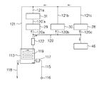
熱交換器113内には、所定の経路に沿って熱交換パイプ119が引き回されており、この熱交換パイプ119は一端側で冷却液供給パイプ120と接続し、他端側で冷却液還流パイプ121と接続される。冷却液供給パイプ120(120a〜120c)はモータジェネレータ29(インバータ31に対する間接的な冷却液供給パイプ120a′の場合を含む)、バッテリ30、エンジン28及び排気管46にそれぞれ接続される。また、インバータ31、バッテリ30、エンジン28及び排気管46にはそれぞれ冷却液還流パイプ121(121a〜121c)が接続される。冷却液供給パイプ120の途中適所には冷却液循環用の電動式循環ポンプ122が配置され(図16参照)、この循環ポンプ122によってこの冷却系で冷却液を循環させる。   In the heat exchanger 113, a heat exchange pipe 119 is routed along a predetermined path. The heat exchange pipe 119 is connected to the coolant supply pipe 120 on one end side, and the coolant recirculates on the other end side. Connected to the pipe 121. Coolant supply pipe 120 (120a to 120c) is connected to motor generator 29 (including an indirect coolant supply pipe 120a 'for inverter 31), battery 30, engine 28, and exhaust pipe 46, respectively. The inverter 31, the battery 30, the engine 28, and the exhaust pipe 46 are connected to the coolant recirculation pipe 121 (121 a to 121 c), respectively. An electric circulation pump 122 for circulating the coolant is arranged at a suitable position in the middle of the coolant supply pipe 120 (see FIG. 16), and the coolant is circulated in the cooling system by the circulation pump 122.

上記の場合、モータジェネレータ29、バッテリ30及びインバータ31、更には排気管46はそれぞれ、所謂ウォータジャケットを有している。それらのウォータジャケット内で冷却液を流通させることで、液冷式に冷却が行われる。なお、エンジン28、モータジェネレータ29、バッテリ30、インバータ31及び排気管46に対して上記のように冷却液を供給する際、それらのウォータジャケットの冷却液供給口にサーモスタット等を装着し、ウォータジャケット内の冷却液の温度に応じて冷却液を供給/遮断するようにすることも可能である。   In the above case, the motor generator 29, the battery 30, the inverter 31, and the exhaust pipe 46 each have a so-called water jacket. Cooling is performed in a liquid-cooled manner by circulating a coolant in the water jacket. When supplying the coolant to the engine 28, the motor generator 29, the battery 30, the inverter 31, and the exhaust pipe 46 as described above, a thermostat or the like is attached to the coolant supply port of these water jackets. It is also possible to supply / shut off the coolant depending on the temperature of the coolant inside.

なおここで、減速機58においてドライブギア65とドリブンギア66は常時、噛合しており、そのためケーシング64内に潤滑油が供給されるようになっている。このため図8あるいは図14等に示されるようにモータジェネレータ29の典型的には右下方には、減速機58に潤滑油を供給するための電動式油圧ポンプ123が配置されている。減速機58のケーシング64と油圧ポンプ123の間は、潤滑油供給パイプ124及び潤滑油回収パイプ125で接続されている。   Here, in the reduction gear 58, the drive gear 65 and the driven gear 66 are always meshed so that the lubricating oil is supplied into the casing 64. For this reason, as shown in FIG. 8 or FIG. 14 and the like, an electric hydraulic pump 123 for supplying lubricating oil to the speed reducer 58 is disposed on the lower right of the motor generator 29 typically. The casing 64 of the reduction gear 58 and the hydraulic pump 123 are connected by a lubricating oil supply pipe 124 and a lubricating oil recovery pipe 125.

また、モータジェネレータ29の左側前方には図10及び図12等に示されるように、ブラケット126を介してバッテリ127(低電圧用)が配置支持される。エンジン28の始動(アイドルストップからの再からの始動を含む)は、基本的にはモータジェネレータ29によって行われる。エンジン28は、この低電圧のバッテリ127で動作する電動スタータを備えている。例えば、高電圧駆動系(バッテリ30、インバータ31、モータジェネレータ29)の運転を休止せざるを得なくなった場合でも、バッテリ127を使ってエンジン28を始動することができ、エンジン出力だけで継続航行が可能である。   A battery 127 (for low voltage) is disposed and supported via a bracket 126 at the front left side of the motor generator 29 as shown in FIGS. Start of the engine 28 (including restart from idle stop) is basically performed by the motor generator 29. The engine 28 includes an electric starter that operates on the low-voltage battery 127. For example, even when the operation of the high voltage drive system (battery 30, inverter 31, motor generator 29) has to be stopped, the engine 28 can be started using the battery 127, and the cruising is continued only with the engine output. Is possible.

上記の場合、船外機10のパワーユニットは、ハイブリッドコントロールユニット及び/又はエンジンコントロールユニットにより最適に制御され、常に適正作動がなされる。例えばバッテリ30の充電状態は常にモニターされ、ハイブリッドコントロールユニットにおいて、必要充電量/放電量がモータジェネレータ29による出力の要求電流に応じて計算され、発電量が決定される。   In the above case, the power unit of the outboard motor 10 is optimally controlled by the hybrid control unit and / or the engine control unit, and is always properly operated. For example, the state of charge of the battery 30 is constantly monitored, and in the hybrid control unit, the required charge amount / discharge amount is calculated according to the output current requested by the motor generator 29 to determine the power generation amount.

また、バッテリ30の状態と舟艇の走行状態によって、モータジェネレータ29と駆動部間にある第2クラッチ78は切離され、モータジェネレータ29で発電した交流電力は全てインバータ31で直流に変換され、バッテリ30に供給される。
更に、バッテリ30の状態と走行状態によって、モータジェネレータ29で発電した交流はインバータ31で直流に変換され、バッテリ30に供給される。エンジン28の動力はモータジェネレータ29による発電と、プロペラ駆動の両方に使用される。
また、バッテリ30の状態と走行状態によって、バッテリ30に蓄えられた電力は直流からインバータで交流に変換され、モータジェネレータ29が駆動される。低速時にはエンジン28は停止し、エンジン28〜モータジェネレータ29間の第1クラッチ67は切離され、モータジェネレータ29のみで推進機を駆動する。
Further, the second clutch 78 between the motor generator 29 and the drive unit is disconnected depending on the state of the battery 30 and the running state of the boat, and all the AC power generated by the motor generator 29 is converted into DC by the inverter 31, 30.
Further, the alternating current generated by the motor generator 29 is converted into direct current by the inverter 31 depending on the state of the battery 30 and the traveling state, and is supplied to the battery 30. The power of the engine 28 is used for both power generation by the motor generator 29 and propeller drive.
Further, depending on the state of the battery 30 and the running state, the electric power stored in the battery 30 is converted from direct current to alternating current by an inverter, and the motor generator 29 is driven. At low speed, the engine 28 is stopped, the first clutch 67 between the engine 28 and the motor generator 29 is disconnected, and the propulsion unit is driven only by the motor generator 29.

また、バッテリ30の状態と走行状態によって、バッテリ30に蓄えられた電力はインバータ29によって直流から交流に変換され、モータジェネレータ29が駆動される。例えば加速時にはエンジン28とモータジェネレータ29の双方で推進機を駆動する。
また、バッテリ30の状態と走行状態によって、モータジェネレータ29は第1クラッチ67によってエンジン28と切離され、減速時に推進機86のプロペラ98で発生するトルクはモータジェネレータ29により交流電流を発生し、インバータ31で直流に変換され、バッテリ30が充電される。
Further, depending on the state of the battery 30 and the traveling state, the electric power stored in the battery 30 is converted from direct current to alternating current by the inverter 29, and the motor generator 29 is driven. For example, during acceleration, the propulsion device is driven by both the engine 28 and the motor generator 29.
Further, depending on the state of the battery 30 and the running state, the motor generator 29 is disconnected from the engine 28 by the first clutch 67, and the torque generated by the propeller 98 of the propulsion device 86 during deceleration generates an alternating current by the motor generator 29. It is converted into direct current by the inverter 31 and the battery 30 is charged.

次に、本発明のハイブリッド式船外機10における主要構成による作用効果等について説明する。
1)先ず、船外機10のパワーユニットを構成する主要部材であるエンジン28、モータジェネレータ29、バッテリ30及びインバータ31がケーシング11内に収容されると共に、該ケーシング11に推進機74が搭載され、これら全体が船外機10として船体外部に一体的に設置される。
Next, functions and effects of the main configuration of the hybrid outboard motor 10 of the present invention will be described.
1) First, the engine 28, the motor generator 29, the battery 30, and the inverter 31 which are main members constituting the power unit of the outboard motor 10 are accommodated in the casing 11, and the propulsion device 74 is mounted on the casing 11. All of them are integrally installed as an outboard motor 10 outside the hull.

舟艇内の空間を占有しないので、船内空間を広く使える。また、船外機10の構成要素が実質的に船外に配置されるので、メンテナンス作業等を簡単に行うことができる。更に特別な装置を用いることなく、船尾部に一括で簡単に取り付けることができる。   Since it does not occupy space in the boat, it can be used widely. Further, since the components of the outboard motor 10 are substantially disposed outside the outboard, maintenance work and the like can be easily performed. Furthermore, it can be easily and collectively attached to the stern without using a special device.

また、作動上、負荷変動に対してエンジン28は効率の良い状態でのみ運転されるので、燃費が良い。特に、アイドリングなど低負荷時にはエンジン28を停止させるので、燃費が良くなる。また、後進−中立−前進の切替えをモータジェネレータ29の回転方向と回転速度を変化させることで行い、即ち通常の内燃機関の場合のようにシフト操作(クラッチとギア)によって行わないので、前進、後進及び加速等を滑らかに切り替えることができる。   Further, in operation, the engine 28 is operated only in an efficient state with respect to load fluctuations, so that fuel efficiency is good. In particular, since the engine 28 is stopped at a low load such as idling, fuel efficiency is improved. Further, reverse-neutral-forward switching is performed by changing the rotational direction and rotational speed of the motor generator 29, that is, it is not performed by a shift operation (clutch and gear) as in the case of a normal internal combustion engine. It is possible to smoothly switch between reverse and acceleration.

2)モータジェネレータ29のモータジェネレータ出力軸75を、チルト軸(チルトシャフト73)と一致させている。
これによりチルト角変化に対して、モータジェネレータ出力軸75とプロペラ軸(プロペラシャフト95)とを例えばユニバーサルジョイント等を用いて曲げる必要がない。このため余分な動力伝達機構等を用いないで済むため機械効率が高く、構造も簡素化して製品価格を廉価にすることができる。また、構造が簡素化することで、故障の発生等を極力抑制することができる。
また、水上係留時、推進機86まわりを水面上に引き上げることができ(図26参照)、耐腐食性や耐汚損性(藻や貝等に起因するもの)に優れる。従って、耐久性を向上することで、製品寿命を長期化することができる。
2) The motor generator output shaft 75 of the motor generator 29 is aligned with the tilt axis (tilt shaft 73).
Accordingly, it is not necessary to bend the motor generator output shaft 75 and the propeller shaft (propeller shaft 95) using, for example, a universal joint or the like with respect to the tilt angle change. For this reason, it is not necessary to use an extra power transmission mechanism or the like, so that the mechanical efficiency is high, the structure is simplified, and the product price can be reduced. In addition, by simplifying the structure, it is possible to suppress the occurrence of failure as much as possible.
Further, when mooring on the water, the propulsion device 86 can be lifted up to the surface of the water (see FIG. 26), and is excellent in corrosion resistance and fouling resistance (those caused by algae, shellfish, etc.). Therefore, the product life can be extended by improving the durability.

更に、水上浮遊物あるいは海底との衝突が仮に発生した際、チルト方向に推進機86を跳ね上げることで、衝突エネルギーを緩和することできる(図24、図25等参照)。
また、水中に浸漬されるギアケース87やプロペラ88等を含む推進機86内に、モータ等を配置しないので、推進機86の水中浸漬部が小さくなる。これにより流体力学的抵抗(以下、ドラッグと言う)が小さくなり、航走性能及び燃費等が向上する。
また、チルトすることで船底からの突出部長さ(深さ)を変えることができるので、浅瀬での航行が可能になる。
また、推進(縦)方向を変えることができるので(トリム機能)、航行時に船体重心、船底形状あるいは船速等で変化する船尾周りの水の流れ分布に最適な推進(縦方向)角度に調整できる。
Furthermore, when a collision with a floating substance on the water or the sea floor occurs, the collision energy can be reduced by jumping up the propulsion device 86 in the tilt direction (see FIG. 24, FIG. 25, etc.).
Moreover, since a motor etc. are not arrange | positioned in the propulsion device 86 containing the gear case 87 immersed in water, the propeller 88, etc., the underwater immersion part of the propulsion device 86 becomes small. As a result, hydrodynamic resistance (hereinafter referred to as “drug”) is reduced, and navigation performance, fuel consumption, and the like are improved.
In addition, since the length (depth) of the protrusion from the ship bottom can be changed by tilting, navigation in shallow water becomes possible.
Also, since the propulsion (vertical) direction can be changed (trim function), it is adjusted to the optimal propulsion (vertical direction) angle for the water flow distribution around the stern, which changes depending on the hull center of gravity, ship bottom shape or ship speed during navigation. it can.

3)モータジェネレータ出力軸75とドライブ軸(ドライブシャフト82)をかさ歯車(ベベルギア79及びピニオン80)で減速しつつ、両者を直交させている。
これによりステアリング角変化に対して、モータジェネレータ出力軸75とプロペラ軸とを例えばユニバーサルジョイント等を用いて曲げる必要がない。このため機械効率が高く、構造も簡素化して製品価格を廉価にすることができる。また、構造が簡素化することで、故障の発生等を極力抑制することができる。
3) While the motor generator output shaft 75 and the drive shaft (drive shaft 82) are decelerated by bevel gears (bevel gear 79 and pinion 80), they are orthogonal to each other.
Thus, it is not necessary to bend the motor generator output shaft 75 and the propeller shaft using, for example, a universal joint with respect to the steering angle change. Therefore, the mechanical efficiency is high, the structure is simplified, and the product price can be reduced. In addition, by simplifying the structure, it is possible to suppress the occurrence of failure as much as possible.

また、推進機86におけるチルト軸から最も離れた位置にある部位(ギアケース87あるいはプロペラ88等)の重量が大きくならないことから、チルト軸周りの可動部分の慣性質量が大きくならない。このため水上浮遊物や海底に衝突した際、チルト軸周りに跳ね上がり衝撃吸収するエネルギーが実質的に小さくなる。従って、衝撃吸収装置が小さくて済むため、船外機全体を軽量且つ廉価にすることができる。更に、チルト角を大きく設定することが可能となる。   Further, since the weight of the portion (the gear case 87 or the propeller 88) located farthest from the tilt axis in the propulsion device 86 does not increase, the inertial mass of the movable part around the tilt axis does not increase. For this reason, when it collides with a floating object or the seabed, the energy that jumps around the tilt axis and absorbs the impact is substantially reduced. Therefore, since the impact absorbing device can be small, the entire outboard motor can be made lightweight and inexpensive. Furthermore, it is possible to set a large tilt angle.

4)ドライブ軸とステアリング軸を一致させている。
これによりステアリング角を大きくできる。
また、チルト角変化に対して、モータジェネレータ出力軸75とプロペラ軸とを例えばユニバーサルジョイント等を用いて曲げる必要がない。このため機械効率が高く、構造も簡素化して製品価格を廉価にすることができる。また、構造が簡素化することで、故障の発生等を極力抑制することができる。
また、ステアリングしてもドライブ軸及びプロペラ軸間、あるいはドライブ軸及びモータジェネレータ出力軸間のそれぞれ相対位置関係が変化しない。これによりシンプルな構成で動力を伝達でき、伝達効率が良い。
4) The drive shaft and the steering shaft are matched.
As a result, the steering angle can be increased.
Further, it is not necessary to bend the motor generator output shaft 75 and the propeller shaft using, for example, a universal joint or the like with respect to the tilt angle change. Therefore, the mechanical efficiency is high, the structure is simplified, and the product price can be reduced. In addition, by simplifying the structure, it is possible to suppress the occurrence of failure as much as possible.
Further, even if steering is performed, the relative positional relationship between the drive shaft and the propeller shaft or between the drive shaft and the motor generator output shaft does not change. Thereby, power can be transmitted with a simple configuration, and transmission efficiency is good.

5)推進(プロペラ)軸と直交鉛直方向にドライブ軸を配置し、両者をギアケース内のかさ歯車(ベベルギア92及びピニオン93)で減速している。
これによりモータジェネレータ29における機械効率の良い比較的高い回転数から、モータジェネレータ軸〜ドライブ軸間減速機(中間減速機)と、ドライブ軸〜プロペラ軸間減速機(最終減速機)の2段で減速する。これにより総合減速比を大きく設定でき、プロペラ88の推進効率の高い比較的低い回転数に減速することができる。また、最終減速機を小さくすることができるので、水中浸漬部のドラッグが増大しない。
5) A drive shaft is arranged in a perpendicular direction perpendicular to the propulsion (propeller) shaft, and both are decelerated by bevel gears (bevel gear 92 and pinion 93) in the gear case.
As a result, the motor generator 29 has two stages: a motor generator shaft-drive shaft speed reducer (intermediate speed reducer) and a drive shaft-propeller shaft speed reducer (final speed reducer) from a relatively high rotational speed with good mechanical efficiency. Slow down. As a result, the overall reduction ratio can be set large, and the speed can be reduced to a relatively low rotational speed with high propulsion efficiency of the propeller 88. Moreover, since the final reduction gear can be made small, the drag of the submerged part does not increase.

6)モータジェネレータ29と中間減速機81の間に、ハイブリッドコントロールユニットによって結/離を制御できる第2クラッチ78を配置している。
これにより推進機86を静止したまま、エンジン28によってモータジェネレータ29を駆動し、発電機として作動させることで発電することができる。この場合、推進機86は静止しているので、発電効率が良い。
6) Between the motor generator 29 and the intermediate reduction gear 81, the 2nd clutch 78 which can control connection / separation with a hybrid control unit is arrange | positioned.
As a result, power can be generated by driving the motor generator 29 by the engine 28 and operating as a generator while the propulsion unit 86 is stationary. In this case, since the propulsion device 86 is stationary, the power generation efficiency is good.

7)エンジン28のクランク軸を舟艇の進行方向と直交配置させている(所謂、横置き内燃機関の配置構造)。
これにより上下方向及び前後方向に張り出さないため、船外機の全体パッケージをコンパクトにすることができる。
また、推進機86の重心が舟艇から後方に大きく離れないため、簡単に滑走状態に移行することができる。
7) The crankshaft of the engine 28 is arranged orthogonal to the traveling direction of the boat (so-called horizontal internal combustion engine arrangement structure).
As a result, the entire package of the outboard motor can be made compact because it does not protrude in the vertical direction and the front-rear direction.
Further, since the center of gravity of the propulsion device 86 is not greatly separated rearward from the boat, it is possible to easily shift to the sliding state.

8)モータジェネレータ軸を舟艇の進行方向と直交配置させている(所謂、横置きモータの配置構造)。
これにより船外機の全体パッケージをコンパクトにすることができる。
また、この場合も推進機86の重心が舟艇から後方に大きく離れないため、簡単に滑走状態に移行することができる。
8) The motor generator shaft is arranged orthogonal to the traveling direction of the boat (so-called horizontal motor arrangement structure).
As a result, the overall package of the outboard motor can be made compact.
Also in this case, since the center of gravity of the propulsion device 86 is not greatly separated backward from the boat, it is possible to easily shift to the sliding state.

9)エンジン28のクランク軸と第1(初段)の減速機入力軸(入力軸59)を一致させている。また、第1の減速機出力軸とモータジェネレータ軸を一致させている。更にエンジン28のクランク軸と第1の減速機入力軸をユニバーサルジョイント57で連結している。また、ユニバーサルジョイント57と第1の減速機入力軸の間にハイブリッドコントロールユニットによって結/離を切り替えることができる第1クラッチ67を設けている。 9) The crankshaft of the engine 28 is matched with the first (first stage) reduction gear input shaft (input shaft 59). Further, the first reduction gear output shaft and the motor generator shaft are made to coincide. Further, the crankshaft of the engine 28 and the first reduction gear input shaft are connected by a universal joint 57. In addition, a first clutch 67 that can be connected / disconnected by the hybrid control unit is provided between the universal joint 57 and the first reduction gear input shaft.

これによりエンジン28の振動がモータジェネレータ29に伝達するのを抑止することができる。所謂、アイドリングストップ後の再始動時、モータジェネレータ29でエンジン28を始動する際に、エンジン28に対してその始動用発電機(モータジェネレータ29)が近接配置されているためエンジン始動時の遅れが少ない。
また、エンジン28及びモータジェネレータ29は駆動部(推進機86)から離されている。駆動部と内燃機関が一体となった従来型船外機と比較すると、駆動部の重量及び慣性モーメントが小さくなるため、チルト動作に必要な(油圧)装置を小さくすることができる。
更に、駆動部をチルト作動やステアリング作動させても、エンジン28の姿勢は変化しないので、エンジン28の冷却や潤滑を簡単且つ的確に行うことができる。このため例えば自動車用内燃機関を利用することができる。
Thereby, the vibration of the engine 28 can be prevented from being transmitted to the motor generator 29. At the time of restart after idling stop, when the engine 28 is started by the motor generator 29, the starter generator (motor generator 29) is disposed close to the engine 28. Few.
The engine 28 and the motor generator 29 are separated from the drive unit (propulsion unit 86). Compared to a conventional outboard motor in which the drive unit and the internal combustion engine are integrated, the weight and moment of inertia of the drive unit are reduced, so that the (hydraulic) device required for the tilting operation can be reduced.
Further, since the attitude of the engine 28 does not change even when the drive unit is tilted or steered, the engine 28 can be cooled and lubricated easily and accurately. For this reason, for example, an automobile internal combustion engine can be used.

また、第1クラッチ67及び第2クラッチ78を適宜使い分けることで、典型的には下記4つの運転モードを選択することができる。
(イ)第1クラッチ結且つ第2クラッチ“結”状態;
エンジン28とモータジェネレータ29でプロペラ88を駆動(加速又は重負荷状態)、又はエンジン28によってプロペラ88を駆動しながら、モータジェネレータ29で発電状態(電池低充電状態)にする。
(ロ)第1クラッチ結且つ第2クラッチ“離”状態;
舟艇は静止、モータジェネレータ29で充電(電池低充電状態)、又はモータジェネレータ29によってエンジン28を始動することができる。
(ハ)第1クラッチ離且つ第2クラッチ“結”状態;
モータジェネレータ29による推進、又は減速時エネルギー回生(エンジン停止)を行うことができる。
(ニ)第1クラッチ離且つ第2クラッチ“離”状態;
否運転状態である。
Further, by appropriately using the first clutch 67 and the second clutch 78, typically, the following four operation modes can be selected.
(A) First clutch engagement and second clutch “connection” state;
The propeller 88 is driven by the engine 28 and the motor generator 29 (acceleration or heavy load state), or while the propeller 88 is driven by the engine 28, the motor generator 29 is in a power generation state (battery low charge state).
(B) First clutch engaged and second clutch "disengaged"state;
The boat can be stationary, charged by the motor generator 29 (battery low charge state), or the engine 28 can be started by the motor generator 29.
(C) The first clutch is disengaged and the second clutch is “engaged”;
Propulsion by the motor generator 29 or energy regeneration during deceleration (engine stop) can be performed.
(D) the first clutch disengaged and the second clutch disengaged;
It is a non-operation state.

10)エンジン28及びモータジェネレータ29が水密のケーシング11で覆われる。
これによりエンジン28及びモータジェネレータ29等の耐食性及び耐汚性を向上することができる。
10) The engine 28 and the motor generator 29 are covered with a watertight casing 11.
Thereby, corrosion resistance and antifouling properties of the engine 28, the motor generator 29, etc. can be improved.

11)水密のケーシング11と船体1を固定する係合部材を設けている。
これによりエンジン28及びモータジェネレータ29を含む船外機全体が、一体的に組み立てられている。なお、この点に関する限り、従来船外機と同様に所謂All-in-One、又はプレアッシーであるため、船体1への取付けを簡単に行うことができ、構成部材各部の相対的位置を調整する必要がない。
11) An engagement member for fixing the watertight casing 11 and the hull 1 is provided.
As a result, the entire outboard motor including the engine 28 and the motor generator 29 is integrally assembled. As far as this point is concerned, since it is a so-called All-in-One or pre-assy like the conventional outboard motor, it can be easily attached to the hull 1 and the relative position of each part of the constituent members can be adjusted. There is no need.

12)上記All-in-Oneによる作用効果は、下記列挙の構成によりそれぞれ同様に達成することができる。
(イ)水密のケーシング11に駆動部のチルト軸受を設けている。
(ロ)水密のケーシング11に駆動部のチルト用油圧駆動装置の固定端(パワートリムチルト99の基端99a)を設けている。
(ハ)水密のケーシング11に駆動部のステアリング用駆動装置の固定端(ステアリング固定ブラケット103)を設けている。
(ニ)水密のケーシング11に交流発電機(モータジェネレータ29)電流を直流に変換するインバータ31、電池(バッテリ30)からの直流を交流電流に変換するインバータ31を設けている。
これらいずによっても、エンジン28及びモータジェネレータ29を含む船外機全体が、一体的に組み立てられ、船体1への取付けを簡単に行うことができ、構成部材各部の相対的位置を調整する必要がない。
12) The effects of the above All-in-One can be similarly achieved by the following listed configurations.
(A) The watertight casing 11 is provided with a tilt bearing of the drive unit.
(B) The watertight casing 11 is provided with a fixed end (base end 99a of the power trim tilt 99) of the hydraulic drive device for tilting of the drive unit.
(C) The watertight casing 11 is provided with a fixed end (steering fixing bracket 103) of the steering driving device of the driving unit.
(D) The watertight casing 11 is provided with an inverter 31 that converts an alternating current (motor generator 29) current into direct current and an inverter 31 that converts direct current from a battery (battery 30) into alternating current.
In any case, the entire outboard motor including the engine 28 and the motor generator 29 can be assembled integrally, can be easily attached to the hull 1, and the relative position of each part of the constituent members needs to be adjusted. There is no.

13)水密のケーシング11内に配置されるエンジン28の燃焼用空気は、ケーシング11及び船体1のトランサムボード2に開けられた貫通孔を経由して配備された吸入空気用筒(吸気管42)から供給される。この場合、空気用筒の船内側開口端は、船体に設けられた波、しぶき及び雨等に直接曝されない部屋に設置されている。 13) The combustion air of the engine 28 disposed in the watertight casing 11 is a cylinder for intake air (intake pipe 42) provided through a through hole opened in the transom board 2 of the casing 11 and the hull 1. Supplied from In this case, the inner opening end of the air cylinder is installed in a room that is not directly exposed to waves, splashes, rain, and the like provided in the hull.

従来の船外機ではカバー(カウリング)内に設けられた内燃機関燃焼用空気を、カバーの空気取入れ口から取り入れていたため、カバー内が負圧になり、空気だけでなく、水(しぶき)もカバー内に入ってくるのを回避するのが難しかった。これに対して船内機や船内外機等と同様に船体における波、しぶき及び雨等に直接曝されていない部屋から空気を取り入れることで、水密のケーシング11は負圧にならず、水(しぶき)がケーシング11内に入ってくるのを防ぐことができる。   In conventional outboard motors, combustion air provided in the cover (cow ring) is taken from the air intake port of the cover, so the inside of the cover becomes negative pressure and not only air but also water (splash) It was difficult to avoid getting into the cover. On the other hand, by taking in air from a room that is not directly exposed to waves, splashes, rain, etc. in the hull like inboard motors and inboard / outboard motors, the watertight casing 11 does not become negative pressure, but water (splash). ) Can be prevented from entering the casing 11.

14)水密のケーシング11内に換気用空気を取り入れるために、ケーシング11及び船体1のトランサムボード2に開けられた貫通孔を経由して配備された換気空気用筒が設けられる。この換気空気用筒の船内側開口端は、船体に設けられた波、しぶき及び雨等に直接曝されない部屋に設置されている。また、換気排出口は、ケーシング11から迷路を経由して外部に導かれる。 14) In order to take in ventilation air into the watertight casing 11, a cylinder for ventilation air is provided through the casing 11 and a through hole opened in the transom board 2 of the hull 1. The inside opening end of the ventilation air cylinder is installed in a room that is not directly exposed to waves, splashes, rain, and the like provided in the hull. Further, the ventilation outlet is led to the outside from the casing 11 via the maze.

水密のケーシング11内の換気ができる。水密のケーシング11内の圧力を正圧に維持することで、水(しぶき)が水密のケーシング11に入るのを防止することができる。   The inside of the watertight casing 11 can be ventilated. By maintaining the pressure in the watertight casing 11 at a positive pressure, water (splash) can be prevented from entering the watertight casing 11.

15)水密のケーシング11の下端を船底3よりも上方に設置している。
これにより水密のケーシング11自体がトランサムボード2の下端(船底3)から盛り上がるように流れる水を受けるため、船体1の船尾を持ち上げる効果が働き、滑走へ移行し易くなる。
15) The lower end of the watertight casing 11 is installed above the ship bottom 3.
As a result, the watertight casing 11 itself receives water flowing so as to rise from the lower end (bottom 3) of the transom board 2, so that the effect of lifting the stern of the hull 1 works and it is easy to shift to the planing.

16)水密のケーシング11の上端をトランサムボード2の上端と同一又は下方に設置している。
これにより船尾部まわり特に後方が実質的に開放され、例えば桟橋等から船尾部に乗り降りし易く、網や釣り魚等を船尾から取込み易い等の優れた利点を有する。因みに、従来では嵩高の船外機によって船尾部まわりが塞がれてしまう。船尾後方を開放することで、船外機の使用性及び使い勝手が格段に向上する。
16) The upper end of the watertight casing 11 is installed at the same or lower position as the upper end of the transom board 2.
As a result, the area around the stern part, in particular, the rear side is substantially opened, and for example, it is easy to get on and off the stern part from a pier or the like, and it has an excellent advantage that it is easy to take in nets, fishing fish, etc. Incidentally, around the stern part is conventionally blocked by a bulky outboard motor. By opening the stern rear, the outboard motor usability and usability are greatly improved.

17)水密のケーシング11の上面部を略平面としている。
船体1と推進装置(水密のケーシング11)の意匠を整合できる。なお、一般に船外機デザインとボートデザインとを両立させるのは容易ではない。
17) The upper surface of the watertight casing 11 is substantially flat.
The design of the hull 1 and the propulsion device (watertight casing 11) can be matched. In general, it is not easy to balance outboard motor design with boat design.

18)水密のケーシング11上部を開閉可能としている。
パワーユニット各部(エンジン/モータジェネレータ/インバータ等)のメンテナンスを極めて容易且つ適切に行うことができる。メンテナンス作業の内容にもよるが、従来では一般に船外機を船体からおろして、外装(カバー)を取り外して後メンテナンス作業を行わざるを得なかった。
18) The upper part of the watertight casing 11 can be opened and closed.
Maintenance of each part of the power unit (engine / motor generator / inverter, etc.) can be performed extremely easily and appropriately. Although it depends on the contents of the maintenance work, conventionally, the outboard motor has been generally removed from the hull, the exterior (cover) removed, and then the maintenance work has to be performed.

19)水密のケーシング11内にエンジン28、モータジェネレータ29、バッテリ30及びインバータ31に対して、これらの冷却液と冷却用海水の熱を交換する熱交換器を設けている。即ち、モータジェネレータ29及びインバータ31を水冷式としている。
エンジン28、モータジェネレータ29及びインバータ31等の内部に直接、冷却用海水を導入しないため、これらの装置もしくは機器の特に内部の耐食性を大幅に上げることができる。因みに、内燃機関については船内機、船内外機と実質的に同様であるが、船外機にあっては基本的に海水を直接取り込むため、耐食性に難がある。
19) A heat exchanger for exchanging heat of the coolant and the seawater for cooling is provided in the watertight casing 11 for the engine 28, the motor generator 29, the battery 30 and the inverter 31. That is, the motor generator 29 and the inverter 31 are water-cooled.
Since the seawater for cooling is not directly introduced into the engine 28, the motor generator 29, the inverter 31, and the like, the internal corrosion resistance of these devices or equipment can be greatly increased. Incidentally, although the internal combustion engine is substantially the same as the inboard motor and the inboard / outboard motor, the outboard motor has a difficulty in corrosion resistance because it basically takes in seawater directly.

20)水密のケーシング11内に冷却用海水を取り込むための電動式汲上げポンプ1177を設けている。
従来の船外機ではドライブ軸上に設置された機械式ポンプによって海水を汲み上げている。このためドライブ軸を逆転させると、そのままではポンプの出入りが逆転してしまうため、モータ(ドライブ軸)逆転で舟艇を後進させるタイプの推進機には利用できない。また、機械式ポンプの場合、ドライブ軸(つまり内燃機関)回転数だけに比例して汲上げ量が決定される。これに対して電動式のポンプとすることで、負荷(内燃機関をガソリンエンジンとするとスロットル開度)と回転数とに応じて発生する熱量に見合う冷却水量のみ汲み上げるので、無駄がなく効率が極めて高い。
20) An electric pump 1177 for taking cooling seawater into the watertight casing 11 is provided.
In conventional outboard motors, seawater is pumped by a mechanical pump installed on the drive shaft. For this reason, if the drive shaft is reversed, pump entry / exit is reversed as it is, so that it cannot be used for a propulsion device that reverses the boat by reversing the motor (drive shaft). In the case of a mechanical pump, the pumping amount is determined in proportion to only the rotational speed of the drive shaft (that is, the internal combustion engine). On the other hand, by using an electric pump, only the amount of cooling water corresponding to the amount of heat generated according to the load (throttle opening when the internal combustion engine is a gasoline engine) and the number of revolutions is pumped, so there is no waste and the efficiency is extremely high. high.

21)水密のケーシング11内にエンジン28、モータジェネレータ29、バッテリ30及びインバータ31と熱交換器113との間で冷却液を循環させる電動式の循環ポンプ122を設けている。
船内外機等における機械式ポンプはドライブ軸(内燃機関)回転数だけに比例した量の冷却液を循環させ、サーモスタット等を用いて必要量のみバイパスさせるようになっている。これに対して電動式とすることで、負荷(内燃機関をガソリンエンジンとするとスロットル開度)と回転数とに応じて発生する熱量に見合う冷却液量のみ循環させるので、無駄がなく効率が極めて高いい。
21) In the watertight casing 11, an electric circulation pump 122 for circulating the coolant between the engine 28, the motor generator 29, the battery 30, and the inverter 31 and the heat exchanger 113 is provided.
A mechanical pump in an inboard / outboard motor or the like circulates an amount of coolant proportional to only the rotational speed of a drive shaft (internal combustion engine), and bypasses only a necessary amount using a thermostat or the like. On the other hand, by using an electric type, only the amount of coolant corresponding to the amount of heat generated according to the load (throttle opening when the internal combustion engine is a gasoline engine) and the number of revolutions is circulated, so there is no waste and the efficiency is extremely high. It ’s expensive.

22)ケーシング11内の装置もしくは機器類又は部材と船体1側の操縦装置との間を、電気的、機械的に接続するコード又はケーブル類26を挿通させるための貫通孔27が形成される。
船体1や推進機86周辺にケーブル類が露出せず安全性、整頓性及び意匠性等等の点で極めて優れている。
22) A through-hole 27 is formed through which a cord or cable 26 for electrical and mechanical connection is inserted between the device or equipment or member in the casing 11 and the control device on the hull 1 side.
Cables are not exposed around the hull 1 and the propulsion device 86, and are excellent in terms of safety, orderliness, design, and the like.

23)エンジン28をガソリンエンジンとしている。
量産規模の大きい4輪用エンジンをベースにすることで、廉価な推進装置を提供することができる。
23) The engine 28 is a gasoline engine.
A low-priced propulsion device can be provided by using a large-scale four-wheel engine as a base.

24)エンジン28をディーゼルエンジンとしている。
上記の場合と同様に量産規模の大きい4輪用エンジンをベースにすることで、廉価な推進装置を提供することができる。
24) The engine 28 is a diesel engine.
As in the case described above, an inexpensive propulsion device can be provided by using a four-wheel engine having a large mass production scale as a base.

25)排気経路中に触媒装置47を設けている。
従来の船外機の場合と異なり、排気通路を本体外に独立して設けることができ、触媒を容易に設置することができる。排気ガスを適正且つ効率的に浄化することができる。
25) A catalyst device 47 is provided in the exhaust path.
Unlike the case of a conventional outboard motor, the exhaust passage can be independently provided outside the main body, and the catalyst can be easily installed. Exhaust gas can be purified appropriately and efficiently.

26)排気経路を、ギアケース87を通じてプロペラ軸周辺に導き、排気ガスを最終的には水中に排出している。
通常の船内機、船内外機あるいは船外機の場合と同様、排気音に関して静粛性を確保することができる。
26) The exhaust path is guided around the propeller shaft through the gear case 87, and the exhaust gas is finally discharged into the water.
As in the case of a normal inboard motor, inboard / outboard motor, or outboard motor, silence can be ensured with respect to exhaust noise.

27)水密のケーシング11内の排気経路(触媒装置下流側)の周囲にウォータジャケットを設けている。
水密のケーシング11内の雰囲気温度が排気通路からの放射で上昇する程度を抑えることができる。
27) A water jacket is provided around the exhaust path (downstream side of the catalyst device) in the watertight casing 11.
The extent to which the ambient temperature in the watertight casing 11 rises due to radiation from the exhaust passage can be suppressed.

28)水密のケーシング11の下面は中凹(鞍形)形状とし、またその凹部18にチルト軸可動部を含む駆動部分を収容している。
凹部18を駆動部を収容可能な位置に設定し、これをセンタ振分けとして両側の箱部内のうちその一方をエンジン28、他方をモータジェネレータ29、バッテリ30及びインバータ31等を収めたので、全体としてバランスのとれた極めてコンパクトな形状もしくは形態にすることができる。
28) The lower surface of the watertight casing 11 has a concave shape (a bowl shape), and the driving portion including the tilt axis movable portion is accommodated in the concave portion 18.
The concave portion 18 is set at a position where the drive unit can be accommodated, and this is the center distribution, and the engine 28 is placed in one of the box portions on both sides, and the motor generator 29, battery 30 and inverter 31 are placed on the other side. It can be in a balanced and extremely compact shape or form.

29)水密のケーシング11の凹部18に、スイベルブラケット84の横方向スラストを支えるための案内部もしくはガイド19を設けている。
ケーシング11の凹部18で横方向スラストを支えるので、全体として剛性が高く、大きな横スラストを簡便な形状で支持することができる。この場合、凹部18の壁面を有効に利用し、特別な構造部材を必要としない。
29) A guide or guide 19 for supporting the lateral thrust of the swivel bracket 84 is provided in the recess 18 of the watertight casing 11.
Since the lateral thrust is supported by the concave portion 18 of the casing 11, the overall rigidity is high and a large lateral thrust can be supported in a simple shape. In this case, the wall surface of the recess 18 is used effectively, and no special structural member is required.

30)水密のケーシング11の凹部18の前側に壁部を設け(凹部18は下面全体ではなく、後方側のみに設けた)、スイベルブラケット84をチルト軸を中心として回転させるための油圧(又は電気)駆動装置の全体を水密のケーシング11の外部に配置する。このように配置することで、水密のケーシング11内外を結ぶ場合と比較して、ケーシング11の水密構造を簡単化することができる。 30) A wall portion is provided on the front side of the concave portion 18 of the watertight casing 11 (the concave portion 18 is provided only on the rear side, not the entire lower surface), and hydraulic pressure (or electric) for rotating the swivel bracket 84 about the tilt axis is provided. ) The entire driving device is arranged outside the watertight casing 11. By arranging in this way, the watertight structure of the casing 11 can be simplified as compared with the case where the inside and outside of the watertight casing 11 are connected.

31)チルト軸が、エンジン28とモータジェネレータ29を結ぶドライブ軸よりも後方又は下方に位置するように設定している。
チルト軸周りの慣性モーメントを小さくできるので、チルト駆動に必要な力量を実質的に小さくすることができる。必要とされる衝撃吸収力を小さくできる。チルト可動部との干渉を避けるための、逃がし部を小さくできるので、全体をコンパクトにできる。
31) The tilt axis is set to be located behind or below the drive axis connecting the engine 28 and the motor generator 29.
Since the moment of inertia around the tilt axis can be reduced, the amount of force required for tilt drive can be substantially reduced. The required shock absorption can be reduced. Since the escape portion for avoiding interference with the tilt movable portion can be made small, the whole can be made compact.

32)ハイブリッドコントロールユニット(モータジェネレータ29、インバータ31及びクラッチ等を制御する)とエンジンコントロールユニットを水密のケーシング11内に設けている。
ハイブリッドシステムが水密のケーシング11内に一つの完成されたユニットとしてパッケージングされているので、ボート等への取付けを極めて簡単且つ的確に行うことができる。これにより船外機の優れた特徴であるAll-in-One性が長期に亘り適正に維持することができる。
32) A hybrid control unit (which controls the motor generator 29, the inverter 31 and the clutch) and an engine control unit are provided in a watertight casing 11.
Since the hybrid system is packaged in the watertight casing 11 as a single completed unit, it can be mounted on a boat or the like very easily and accurately. As a result, the All-in-One property, which is an excellent feature of outboard motors, can be properly maintained over a long period of time.

33)モータジェネレータ29及びインバータ31と接続されるエネルギー貯蔵装置(高電圧用バッテリ30)とは別に、エンジンコントロール用に低電圧用バッテリ127を水密のケーシング11内に設けている。
エンジン28を普及型(一般に量産されているもの)コントロールユニットで運転することができ、実質的にコスト低減を図ることができる。
33) Apart from the energy storage device (high voltage battery 30) connected to the motor generator 29 and the inverter 31, a low voltage battery 127 is provided in the watertight casing 11 for engine control.
The engine 28 can be operated by a popular type (generally mass-produced) control unit, and the cost can be substantially reduced.

さて、本発明の要旨は、上述したハイブリッド式船外機10において特に、パワーユニットの動力をスクリュー(プロペラ88)に伝達する動力伝達系において、ケーシング11内で船幅方向に並置されたエンジン28とモータジェネレータ29とが連結機構(ユニバーサルジョイント57)を介して連結されると共に、モータジェネレータ29とプロペラ88を含む推進機86とが第2の連結機構(ベベルギア79及びピニオン80)を介して連結され、エンジン28及び/又はモータジェネレータ29を推進機86に接続し、プロペラ88を回転駆動するようにした、点にある。   The gist of the present invention is that, in the above-described hybrid outboard motor 10, particularly in the power transmission system that transmits the power of the power unit to the screw (propeller 88), the engine 28 juxtaposed in the ship width direction in the casing 11. The motor generator 29 is connected via a connecting mechanism (universal joint 57), and the motor generator 29 and the propulsion device 86 including the propeller 88 are connected via a second connecting mechanism (bevel gear 79 and pinion 80). The engine 28 and / or the motor generator 29 are connected to the propulsion device 86, and the propeller 88 is driven to rotate.

船外機10の動力源としてエンジン28とモータジェネレータ29を有し、舟艇の走行状態に応じてこれらの2つの動力源の動力を選択的に使用する。これにより作動上、負荷変動に対してエンジン28は効率の良い状態でのみ運転されるので、燃費が良い。特に、アイドリングなど低負荷時にはエンジン28を停止させるので、燃費が良くなる。また、後進−中立−前進の切替えをモータジェネレータ29の回転方向と回転速度を変化させることで行い、即ち通常の内燃機関の場合のようにシフト操作(クラッチとギア)によって行わないので、前進、後進及び加速等を滑らかに切り替えることができる。   An engine 28 and a motor generator 29 are provided as power sources for the outboard motor 10, and the powers of these two power sources are selectively used according to the traveling state of the boat. As a result, in operation, the engine 28 is operated only in an efficient state with respect to load fluctuations, so that fuel efficiency is good. In particular, since the engine 28 is stopped at a low load such as idling, fuel efficiency is improved. Further, reverse-neutral-forward switching is performed by changing the rotational direction and rotational speed of the motor generator 29, that is, it is not performed by a shift operation (clutch and gear) as in the case of a normal internal combustion engine. It is possible to smoothly switch between reverse and acceleration.

また、本発明においてエンジン28とモータジェネレータ29との間に第1の減速機(減速機58)が配置され、モータジェネレータ29と推進機86との間に第2の減速機(中間減速機81)が配置され、推進機86内に第3の減速機(最終減速機94)が配置される。   In the present invention, a first reduction gear (reduction gear 58) is disposed between the engine 28 and the motor generator 29, and a second reduction gear (intermediate reduction gear 81) is provided between the motor generator 29 and the propulsion device 86. ) Is arranged, and the third reduction gear (final reduction gear 94) is arranged in the propulsion device 86.

動力源であるエンジン28又はモータジェネレータ29からプロペラ88に至る動力伝達系において、初段、中段及び終段の減速機を経てプロペラ88を駆動するようになっている。中段減速比×終段減速比がモータジェネレータ29及びプロペラ88間の総合減速比となり、初段減速比×中段減速比×終段減速比がエンジン28及びプロペラ88間の総合減速比となり、初段減速比がエンジン16及びモータジェネレータ17間の減速比となる。このように減速比を設定することでエンジン28、モータジェネレータ29及びプロペラ88のそれぞれ効率が最もよくなるように組み合わせている。   In the power transmission system from the engine 28 or the motor generator 29 that is a power source to the propeller 88, the propeller 88 is driven through first-stage, middle-stage, and final-stage reducers. The intermediate reduction ratio × the final reduction ratio is the overall reduction ratio between the motor generator 29 and the propeller 88, and the initial reduction ratio × the intermediate reduction ratio × the final reduction ratio is the overall reduction ratio between the engine 28 and the propeller 88. Is the reduction ratio between the engine 16 and the motor generator 17. By setting the reduction ratio in this way, the engine 28, the motor generator 29, and the propeller 88 are combined so that the respective efficiencies are the best.

また、本発明においてエンジン28とモータジェネレータ29との間に第1クラッチ67が配置され、モータジェネレータ29と推進機86側との間に第2クラッチ78が配置される。
この場合、第1クラッチ28は、ユニバーサルジョイント57と第1の減速機との間に介装され、第2クラッチ78は、モータジェネレータ29と第2の連結機構との間に介装される。
In the present invention, the first clutch 67 is disposed between the engine 28 and the motor generator 29, and the second clutch 78 is disposed between the motor generator 29 and the propulsion device 86.
In this case, the first clutch 28 is interposed between the universal joint 57 and the first speed reducer, and the second clutch 78 is interposed between the motor generator 29 and the second coupling mechanism.

第1クラッチ67及び第2クラッチ78はそれぞれ、動力伝達経路の所定部位を接続・切離することがき、これらのクラッチ67,78を使い分けることで、走行状態に応じて最適な運転モードを選択することができる。   Each of the first clutch 67 and the second clutch 78 can connect / disconnect a predetermined portion of the power transmission path, and selects an optimal operation mode according to the running state by using these clutches 67 and 78 properly. be able to.

即ち、前述したように第1クラッチ67を“結”状態とし、第2クラッチ78を“結”状態とすることで、エンジン28とモータジェネレータ29でプロペラ88を駆動し、又はエンジン28によってプロペラ88を駆動しながら、モータジェネレータ29で発電状態にする。
また、第1クラッチ67を“結”状態とし、第2クラッチ78を“離”状態とすることで、舟艇は静止し、モータジェネレータ29で充電し、又はモータジェネレータ29によってエンジン28を始動することができる。
また、第1クラッチ67を“離”状態とし、第2クラッチ78を“結”状態とすることで、モータジェネレータ29によって推進し、又は減速時エネルギー回生を行うことができる。
また、第1クラッチ67を“離”状態とし、第2クラッチ78を“離”状態とすることで、否運転状態となる。
That is, as described above, the first clutch 67 is set to the “connected” state and the second clutch 78 is set to the “connected” state, whereby the propeller 88 is driven by the engine 28 and the motor generator 29, or the propeller 88 is driven by the engine 28. Is driven by the motor generator 29.
Further, by setting the first clutch 67 in the “engaged” state and the second clutch 78 in the “disengaged” state, the boat stops and is charged by the motor generator 29 or the engine 28 is started by the motor generator 29. Can do.
Further, by setting the first clutch 67 in the “disengaged” state and the second clutch 78 in the “engaged” state, the motor generator 29 can be used for propulsion or energy regeneration during deceleration.
Further, when the first clutch 67 is set to the “released” state and the second clutch 78 is set to the “released” state, the non-operation state is set.

また、本発明において第2の連結機構(ベベルギア79及びピニオン80)において第2の減速機(中間減速機81)が構成される。   In the present invention, the second reduction mechanism (intermediate reduction gear 81) is configured in the second coupling mechanism (bevel gear 79 and pinion 80).

モータジェネレータ29及び推進機86間をベベルギア79及びピニオン80を介して連結するが、この部分で連結機構自体により減速機を構成される。これにより構造の簡素化を図ることができる。   The motor generator 29 and the propulsion device 86 are connected to each other via a bevel gear 79 and a pinion 80. In this portion, a reduction mechanism is configured by the connection mechanism itself. As a result, the structure can be simplified.

また、本発明においてエンジン28のクランク軸と減速機58の入力軸59とを一致させると共に、減速機58の出力軸(モータジェネレータ出力軸75)とモータジェネレータ29の回転軸(ロータ軸72)と一致させている。   In the present invention, the crankshaft of the engine 28 and the input shaft 59 of the speed reducer 58 are matched with each other, and the output shaft of the speed reducer 58 (motor generator output shaft 75) and the rotation shaft of the motor generator 29 (rotor shaft 72). Match.

これによりエンジン28の振動がモータジェネレータ29に直接伝達するのを抑止することができる。所謂、アイドリングストップ後の再始動時、モータジェネレータ29でエンジン28を始動する際に、エンジン28に対してその始動用発電機(モータジェネレータ29)が近接配置されているためエンジン始動時の遅れが少ない。   As a result, the vibration of the engine 28 can be prevented from being directly transmitted to the motor generator 29. At the time of restart after idling stop, when the engine 28 is started by the motor generator 29, the starter generator (motor generator 29) is disposed close to the engine 28, so that there is a delay in starting the engine. Few.

このように本発明によれば、極めてコンパクトに構成され、舟艇に一体的且つコンパクトに搭載可能なハイブリッド式船外機10を実現する。その際、従来の船外機が有する種々の課題等を解決しながら、舟艇に搭載されて優れた作用効果を発揮することができる。   As described above, according to the present invention, the hybrid outboard motor 10 which is extremely compact and can be integrally and compactly mounted on a boat is realized. At that time, while solving various problems and the like of the conventional outboard motor, it can be mounted on a boat and exhibit excellent operational effects.

また特に、コンパクト化や高性能化等を図りながら、制限されたスペース内で動力源の動力を適正且つ効率的に伝達することができる。このように効率的に動力伝達することにより燃費や電力消費を有効に低減し、所謂“省エネ”等に極めて効果的に寄与する。   In particular, the power of the power source can be transmitted appropriately and efficiently in a limited space while achieving compactness and high performance. By efficiently transmitting power in this way, fuel consumption and electric power consumption are effectively reduced, contributing to so-called “energy saving” and the like very effectively.

以上、本発明を実施形態と共に説明したが、本発明はこれらの実施形態にのみ限定されるものではなく、本発明の範囲内で変更等が可能である。
例えば動力伝達経路中に配設される第1〜第3の減速機の減速比等は、エンジン28の排気量あるいはモータジェネレータ29の出力等に応じて適宜設定することができる。
As mentioned above, although this invention was demonstrated with embodiment, this invention is not limited only to these embodiment, A change etc. are possible within the scope of the present invention.
For example, the reduction ratios of the first to third reduction gears arranged in the power transmission path can be appropriately set according to the displacement of the engine 28, the output of the motor generator 29, or the like.

1 船体、2 トランサムボード、2a 頂部、3 船底、4 船床、4a 船床段部、10 ハイブリッド式船外機、11 ケーシング、11a 前面部、11b 上面部、11c 凹部、11d 後面部、11e 底面部、12 ケーシング本体、13 カバー、14 ベース板、15 取付穴、15A 上側取付穴、15B 下側取付穴、16 ヒンジ、17 シール、18 凹部、18a 前壁、18b 側壁、19 ガイド、20 貫通孔、21 燃料タンク、22 燃料パイプ、23 貫通孔、24 換気空気用筒体、25 貫通孔、26 ケーブル類、27 貫通孔、28 エンジン、29 モータジェネレータ、30 バッテリ(高電圧用)、31 インバータ、32 シリンダブロック、33 クランクケース、34 シリンダボア、35 ピストン、36 コンロッド、37 クランクシャフト、38 フライホイール、39 エンジン出力軸、40 点火プラグ、41 シリンダヘッド、42 吸気管、42a 空気取込み口、43 吸気マニホールド、44 スロットルボディ、45 排気マニホールド、46 排気管、47 触媒装置、48 排気案内管、48a 排気導入口、48b 排気排出口、49 オイルパン、50 オイルフィルタ、51 冷却水ポンプ、52 ドライブプーリ、53 ドリブンプーリ、54 ガイドプーリ、55 タイミングベルト、56 マウント、57 ユニバーサルジョイント、58 減速機、59 入力軸、60 主ブラケット、60a,60b 孔、61 モータブラケット、62 ブーツ、63 パッキン、64 ケーシング、65 ドライブギア、65a 回転軸、66 ドリブンギア、66a 回転軸、67 第1クラッチ、68 支持ブラケット、69 支持ブラケット、70 三相交流用電気配線、71 直流用電気配線、72 ロータ軸、73 チルトシャフト、74 チルト軸受、75 モータジェネレータ出力軸、76 軸受、77 シール、78 第2クラッチ、79 ベベルギア、80 ピニオン、81 中間減速機、82 ドライブシャフト、83 ドライブシャフトケース、84 スイベルブラケット、85 ロアステアリングブラケット、86 推進機、87 ギアケース、88 プロペラ、89 軸受部、90 ドライブシャフトハウジング、91 軸受、92 ベベルギア、93 ピニオン、94 最終減速機、95 プロペラシャフト、96,97 軸受、98 ベアリングハウジング、99 パワートリムチルト、100 油圧シリンダ、100a トリムロッド、101 油圧シリンダ、101a チルトロッド、102 突当てアーム、103 ステアリング固定ブラケット、104 ステアリングロッド、105 ステアリングシリンダ、106 油圧配管エルボ、107 ステアリング可動ブラケット、108 連結ピン、109 接続部、109a 遮蔽部材、110 環状スペース、111 排気通路、112 排気集合部、113 熱交換器、114 ブラケット、115 海水汲上げパイプ、116 海水取込み口、117 電動式汲上げポンプ、118 排水パイプ、119 熱交換パイプ、120 冷却液供給パイプ、121 冷却液還流パイプ、122 電動式循環ポンプ、123 電動式油圧ポンプ、124 潤滑油供給パイプ、125 潤滑油回収パイプ、126 ブラケット、127 バッテリ(低電圧用)。 DESCRIPTION OF SYMBOLS 1 Hull, 2 Transom board, 2a Top part, 3 Ship bottom, 4 Ship floor, 4a Ship floor step part, 10 Hybrid type outboard motor, 11 Casing, 11a Front surface part, 11b Upper surface part, 11c Recessed part, 11d Rear surface part, 11e Bottom surface Part, 12 casing body, 13 cover, 14 base plate, 15 mounting hole, 15A upper mounting hole, 15B lower mounting hole, 16 hinge, 17 seal, 18 recess, 18a front wall, 18b side wall, 19 guide, 20 through hole , 21 Fuel tank, 22 Fuel pipe, 23 Through hole, 24 Ventilation air cylinder, 25 Through hole, 26 Cables, 27 Through hole, 28 Engine, 29 Motor generator, 30 Battery (for high voltage), 31 Inverter, 32 Cylinder block, 33 Crankcase, 34 Cylinder bore, 35 Piston, 36 Connecting rod, 37 Crankshaft, 38 Flywheel, 39 Engine output shaft, 40 Spark plug, 41 Cylinder head, 42 Intake pipe, 42a Air intake port, 43 Intake manifold, 44 Throttle body, 45 Exhaust manifold, 46 Exhaust pipe, 47 Catalyst device, 48 Exhaust guide pipe, 48a Exhaust inlet, 48b Exhaust outlet, 49 Oil pan, 50 Oil filter, 51 Cooling water pump, 52 Drive pulley, 53 Driven pulley, 54 Guide pulley, 55 Timing belt, 56 Mount, 57 Universal joint, 58 Reducer, 59 Input shaft, 60 Main bracket, 60a, 60b Hole, 61 Motor bracket, 62 Boot, 63 Packing, 64 Casing, 65 Drive gear, 65a Rotating shaft , 66 Driven gear, 66a Rotating shaft, 67 First clutch, 68 Support bracket, 69 Support bracket, 70 Three-phase AC wiring, 71 DC wiring, 72 Rotor shaft, 73 Tilt shaft, 74 Tilt bearing, 75 Motor Generator output shaft, 76 bearing, 77 seal, 78 second clutch, 79 bevel gear, 80 pinion, 81 intermediate reduction gear, 82 drive shaft, 83 drive shaft case, 84 swivel bracket, 85 lower steering bracket, 86 propulsion device, 87 gear Case, 88 propeller, 89 bearing, 90 drive shaft housing, 91 bearing, 92 bevel gear, 93 pinion, 94 final reducer, 95 propeller shaft, 96,97 bearing, 98 bearing housing, 99 parts -Trim tilt, 100 Hydraulic cylinder, 100a Trim rod, 101 Hydraulic cylinder, 101a Tilt rod, 102 Abutting arm, 103 Steering fixing bracket, 104 Steering rod, 105 Steering cylinder, 106 Hydraulic piping elbow, 107 Steering movable bracket, 108 Connecting pin, 109 connecting portion, 109a shielding member, 110 annular space, 111 exhaust passage, 112 exhaust collecting portion, 113 heat exchanger, 114 bracket, 115 seawater pumping pipe, 116 seawater intake port, 117 electric pumping pump, 118 drainage pipe 119 Heat exchange pipe, 120 Coolant supply pipe, 121 Coolant return pipe, 122 Electric circulation pump, 123 Electric hydraulic pump, 124 Lubricating oil supply pipe, 25 lubricating oil collecting pipe, 126 bracket, 127 battery (low voltage).

Claims (6)

ケーシング内部にパワーユニットを収容すると共に該ケーシング外部にスクリューを配置し、前記パワーユニットによって前記スクリューを駆動するハイブリッド式船外機であって、
前記パワーユニットの動力を前記スクリューに伝達する動力伝達系において、前記ケーシング内で船幅方向に並置された内燃機関と発電機兼用電動モータとが連結機構を介して連結されると共に、前記電動モータと前記スクリューを含む推進機とが第2の連結機構を介して連結され、
前記内燃機関及び/又は前記電動モータを前記推進機に接続し、前記スクリューを回転駆動するようにしたことを特徴とするハイブリッド式船外機。
A hybrid-type outboard motor that houses a power unit inside a casing and arranges a screw outside the casing, and drives the screw by the power unit,
In the power transmission system for transmitting the power of the power unit to the screw, an internal combustion engine juxtaposed in the ship width direction in the casing and a generator combined electric motor are connected via a connection mechanism, and the electric motor A propulsion unit including the screw is connected via a second connection mechanism;
A hybrid outboard motor, wherein the internal combustion engine and / or the electric motor is connected to the propulsion device, and the screw is driven to rotate.
前記内燃機関と前記電動モータとの間に第1の減速機が配置され、前記電動モータと前記推進機との間に第2の減速機が配置され、前記推進機内に第3の減速機が配置されることを特徴とする請求項1に記載のハイブリッド式船外機。   A first speed reducer is disposed between the internal combustion engine and the electric motor, a second speed reducer is disposed between the electric motor and the propulsion device, and a third speed reducer is disposed in the propulsion device. The hybrid outboard motor according to claim 1, wherein the hybrid outboard motor is arranged. 前記内燃機関側と前記電動モータ側との間に第1のクラッチが配置され、前記電動モータ側と前記推進機側との間に第2のクラッチが配置されることを特徴とする請求項1又は2に記載のハイブリッド式船外機。   The first clutch is disposed between the internal combustion engine side and the electric motor side, and the second clutch is disposed between the electric motor side and the propulsion device side. Or the hybrid type outboard motor of 2. 前記第1のクラッチは、前記連結機構と前記第1の減速機との間に介装され、前記第2のクラッチは、前記電動モータと前記第2の連結機構との間に介装されることを特徴とする請求項3に記載のハイブリッド式船外機。   The first clutch is interposed between the coupling mechanism and the first reduction gear, and the second clutch is interposed between the electric motor and the second coupling mechanism. The hybrid outboard motor according to claim 3. 前記第2の連結機構において前記第2の減速機が構成されることを特徴とする請求項2〜4のいずれか1項に記載のハイブリッド式船外機。   The hybrid outboard motor according to any one of claims 2 to 4, wherein the second reduction gear is configured in the second coupling mechanism. 前記内燃機関のクランク軸と前記第1の減速機の入力軸とを一致させると共に、前記第1の減速機の出力軸と前記電動モータの回転軸と一致させることを特徴とする請求項2〜5のいずれか1項に記載のハイブリッド式船外機。   The crankshaft of the internal combustion engine and the input shaft of the first speed reducer are made to coincide with each other, and the output shaft of the first speed reducer and the rotation shaft of the electric motor are made to coincide with each other. The hybrid outboard motor according to any one of 5.
JP2009077045A 2009-03-26 2009-03-26 Hybrid type outboard motor Pending JP2010228530A (en)

Priority Applications (2)

Application Number Priority Date Filing Date Title
JP2009077045A JP2010228530A (en) 2009-03-26 2009-03-26 Hybrid type outboard motor
US12/731,342 US8298023B2 (en) 2009-03-26 2010-03-25 Hybrid outboard motor

Applications Claiming Priority (1)

Application Number Priority Date Filing Date Title
JP2009077045A JP2010228530A (en) 2009-03-26 2009-03-26 Hybrid type outboard motor

Publications (2)

Publication Number Publication Date
JP2010228530A true JP2010228530A (en) 2010-10-14
JP2010228530A5 JP2010228530A5 (en) 2011-08-18

Family

ID=43044784

Family Applications (1)

Application Number Title Priority Date Filing Date
JP2009077045A Pending JP2010228530A (en) 2009-03-26 2009-03-26 Hybrid type outboard motor

Country Status (1)

Country Link
JP (1) JP2010228530A (en)

Cited By (8)

* Cited by examiner, † Cited by third party
Publication number Priority date Publication date Assignee Title
GB2554045A (en) * 2016-06-10 2018-03-28 Hush Craft Ltd Boat auxiliary propulsion unit
WO2020054217A1 (en) * 2018-09-13 2020-03-19 ヤンマー株式会社 Ship propulsion hybrid system
JP2020090220A (en) * 2018-12-06 2020-06-11 スズキ株式会社 Outboard motor provided with idling stop function
WO2021040297A1 (en) * 2019-08-26 2021-03-04 주식회사 빈센 Modularized electric propulsion apparatus for ships
WO2023187887A1 (en) * 2022-03-28 2023-10-05 本田技研工業株式会社 Electric outboard motor and vessel
GB2618343A (en) * 2022-05-03 2023-11-08 Mathwall Engineering Ltd Buoyant Stern Structure
WO2023214168A1 (en) * 2022-05-03 2023-11-09 Mathwall Engineering Limited Buoyant stern structure
CN117279830A (en) * 2023-03-30 2023-12-22 广东逸动科技有限公司 Limit protection method, warping device, propeller, equipment and storage medium

Cited By (10)

* Cited by examiner, † Cited by third party
Publication number Priority date Publication date Assignee Title
GB2554045A (en) * 2016-06-10 2018-03-28 Hush Craft Ltd Boat auxiliary propulsion unit
WO2020054217A1 (en) * 2018-09-13 2020-03-19 ヤンマー株式会社 Ship propulsion hybrid system
JP2020090220A (en) * 2018-12-06 2020-06-11 スズキ株式会社 Outboard motor provided with idling stop function
JP7172532B2 (en) 2018-12-06 2022-11-16 スズキ株式会社 Outboard motor with idling stop function
WO2021040297A1 (en) * 2019-08-26 2021-03-04 주식회사 빈센 Modularized electric propulsion apparatus for ships
US11254406B2 (en) 2019-08-26 2022-02-22 Vinssen Co., Ltd Modular electric propulsion device for ships
WO2023187887A1 (en) * 2022-03-28 2023-10-05 本田技研工業株式会社 Electric outboard motor and vessel
GB2618343A (en) * 2022-05-03 2023-11-08 Mathwall Engineering Ltd Buoyant Stern Structure
WO2023214168A1 (en) * 2022-05-03 2023-11-09 Mathwall Engineering Limited Buoyant stern structure
CN117279830A (en) * 2023-03-30 2023-12-22 广东逸动科技有限公司 Limit protection method, warping device, propeller, equipment and storage medium

Similar Documents

Publication Publication Date Title
US8333626B2 (en) Hybrid outboard motor
US8298023B2 (en) Hybrid outboard motor
JP5293335B2 (en) Hybrid outboard motor
US10933962B2 (en) Large outboard motor for marine vessel application and related methods of making and operating same
JP2010228530A (en) Hybrid type outboard motor
US20070135000A1 (en) Outboard jet drive marine propulsion system
JP5293334B2 (en) Hybrid outboard motor
JP5293332B2 (en) Hybrid outboard motor
JP5195571B2 (en) Hybrid outboard motor
DK3168135T3 (en) Outboard Motor
JP2010228528A (en) Hybrid type outboard motor
CA3132279A1 (en) A marine outboard motor with drive shaft and cooling system
JP2012246881A (en) Exhaust device of outboard motor
NO20210337A1 (en) Hybrid outboard engine
JP5621529B2 (en) Muffler room and muffler cover structure for outboard engine case
JP5625775B2 (en) Outboard engine case

Legal Events

Date Code Title Description
A521 Written amendment

Free format text: JAPANESE INTERMEDIATE CODE: A523

Effective date: 20110630