JP2010223294A - Dry-type frictional material - Google Patents
Dry-type frictional material Download PDFInfo
- Publication number
- JP2010223294A JP2010223294A JP2009070024A JP2009070024A JP2010223294A JP 2010223294 A JP2010223294 A JP 2010223294A JP 2009070024 A JP2009070024 A JP 2009070024A JP 2009070024 A JP2009070024 A JP 2009070024A JP 2010223294 A JP2010223294 A JP 2010223294A
- Authority
- JP
- Japan
- Prior art keywords
- friction material
- dry
- core metal
- dry friction
- material base
- Prior art date
- Legal status (The legal status is an assumption and is not a legal conclusion. Google has not performed a legal analysis and makes no representation as to the accuracy of the status listed.)
- Pending
Links
Images


Abstract
Description
本発明は、乾式の摩擦材、例えば、自動車等に用いられるトルクリミッター等を構成する乾式摩擦材に関し、特に、芯金に対する摩擦材基材の取付けが容易な乾式摩擦材に関するものである。 The present invention relates to a dry friction material, for example, a dry friction material constituting a torque limiter used in an automobile or the like, and more particularly to a dry friction material in which a friction material substrate can be easily attached to a metal core.
クラッチフェーシング、ダンパー、トルクリミッター等を始めとする乾式摩擦材を含むシステムにおいて、乾式摩擦材の製造方法としては、特許文献1に示されるように、基材となるガラス長繊維を束ねた繊維束(ガラスロービング)に熱硬化性樹脂を含む含浸液を含浸させて樹脂含浸紐を形成する樹脂含浸工程と、樹脂含浸紐に配合ゴムを付着させるゴム付着工程とを有し、含浸液の媒体は水であり、熱硬化性樹脂はメラミン配合率が30%〜80%の水性メラミン変性フェノール樹脂である方法が知られている。
In a system including a dry friction material such as a clutch facing, a damper, a torque limiter, etc., as a dry friction material manufacturing method, as shown in
この特許文献1の技術によれば、樹脂含浸工程でもゴム付着工程でも有機溶媒を使用することなしに、最終製品の乾式摩擦材(クラッチフェーシング等)の性能が低下しない摩擦材用素材(摩擦材基材)を製造することができる。この摩擦材基材をリング形状等の所定形状に切断して芯金(コアプレート)に取付ける方法としては、特許文献2に示されるように、接着剤で貼り付ける方法やリベットを用いて固定する方法が一般的である。
According to the technique of this
特に、接着剤で貼り付ける方法は、自動化も容易であるため広く取り入れられているが、芯金に対する位置合わせ及び芯合わせが不十分になり易いという問題があった。そこで、特許文献3においては、芯金の外周に少なくとも3個以上配置された位置決め部材によって、芯金の外径より小さい外径を有する環状の摩擦材基材を所定のオフセット量で位置決めする工程と、芯金に対して摩擦材基材を押圧接着する工程とからなる摩擦材(フリクションプレート)の製造方法の発明について開示している。
In particular, the method of attaching with an adhesive is widely adopted because it is easy to automate, but there is a problem that the alignment and the alignment with respect to the metal core tend to be insufficient. Therefore, in
しかしながら、上記特許文献2に記載の技術においても特許文献3に記載の技術においても、取付け材料として接着剤またはリベットを必要とするとともに、接着工程またはリベットカシメ工程が余分に必要となるため、摩擦材の製造コストが上昇してしまうという問題点があった。
However, both the technique described in
そこで、本発明は、かかる課題を解決すべくなされたものであって、接着剤やリベット等の余分な取付け材料を必要とせず、余分な工程も省略することができて、製造コストを低減することができる乾式摩擦材の提供を目的とするものである。 Therefore, the present invention has been made to solve such a problem, and does not require an extra attachment material such as an adhesive or a rivet, and can eliminate an extra process, thereby reducing the manufacturing cost. An object of the present invention is to provide a dry friction material.
請求項1の発明に係る乾式摩擦材は、平板リング形状の芯金の片面または両面に平板リング形状の摩擦材基材が取付けられてなる乾式摩擦材であって、前記摩擦材基材は常時前記芯金に押し付けられており、前記芯金及び/または前記摩擦材基材には、前記摩擦材基材を前記芯金に対して同芯に位置決めするための位置決め手段が設けられたものである。
The dry friction material according to the invention of
ここで、「位置決め手段」としては、芯金に設けられた二箇所以上の凸部と摩擦材基材に設けられた凸部に嵌合する同数の凹部若しくは貫通孔、芯金に設けられた二箇所以上の凹部若しくは貫通孔と摩擦材基材に設けられた凹部若しくは貫通孔に嵌合する同数の凸部、摩擦材基材の外周側面及び/または内周側面に設けられたテーパーとこのテーパーに係合する芯金に設けられたフック、芯金に設けられた摩擦材基材の外周側面及び内周側面に接する複数の位置決めピン、芯金に設けられたガイドレール、等を用いることができる。 Here, as the “positioning means”, two or more convex portions provided on the core metal and the same number of concave portions or through-holes fitted to the convex portions provided on the friction material base material are provided on the core metal. Two or more recesses or through holes and the same number of protrusions fitted in the recesses or through holes provided in the friction material base, a taper provided on the outer peripheral side surface and / or inner peripheral side surface of the friction material base Use hooks provided on the metal core engaged with the taper, a plurality of positioning pins in contact with the outer peripheral side surface and inner peripheral side surface of the friction material base provided on the metal core, guide rails provided on the metal core, etc. Can do.
請求項2の発明に係る乾式摩擦材は、請求項1の構成において、前記位置決め手段は、前記芯金に設けられた二箇所以上の凸部と前記摩擦材基材に設けられた前記凸部に嵌合する同数の凹部若しくは貫通孔、及び/または前記芯金に設けられた二箇所以上の凹部若しくは貫通孔と前記摩擦材基材に設けられた前記凹部若しくは前記貫通孔に嵌合する同数の凸部であるものである。 The dry friction material according to a second aspect of the present invention is the dry friction material according to the first aspect, wherein the positioning means includes two or more convex portions provided on the core metal and the convex portion provided on the friction material base material. The same number of recesses or through-holes to be fitted to each other and / or two or more recesses or through-holes provided in the core metal and the same number to be fitted to the recesses or through-holes provided in the friction material base It is a convex part.
請求項3の発明に係る乾式摩擦材は、請求項2の構成において、前記凹部または前記貫通孔の内径が入り口から奥に向かって小さくなるテーパー形状を有しているものである。 According to a third aspect of the present invention, the dry friction material according to the second aspect has a tapered shape in which the inner diameter of the concave portion or the through hole decreases from the entrance toward the back.
請求項4の発明に係る乾式摩擦材は、請求項2または請求項3の構成において、前記凸部の外周または前記凹部若しくは前記貫通孔の内周が凹凸の連続する波形形状であるものである。 A dry friction material according to a fourth aspect of the present invention is the structure of the second or third aspect, wherein the outer periphery of the convex portion or the inner periphery of the concave portion or the through hole has a corrugated shape with continuous irregularities. .
請求項5の発明に係る乾式摩擦材は、請求項2乃至請求項4のいずれか1つの構成において、前記凹部または前記貫通孔の内部にOリングが嵌め込まれたものである。 A dry friction material according to a fifth aspect of the present invention is the dry friction material according to any one of the second to fourth aspects, wherein an O-ring is fitted into the recess or the through hole.
請求項6の発明に係る乾式摩擦材は、請求項2乃至請求項5のいずれか1つの構成において、前記二箇所以上の凹部若しくは貫通孔の中心と前記二箇所以上の凸部の中心とが、一部または全部について、前記芯金の側が外周側に位置するようにずれたものである。 A dry friction material according to a sixth aspect of the present invention is the dry friction material according to any one of the second to fifth aspects, wherein the centers of the two or more concave portions or through holes and the centers of the two or more convex portions are formed. In this case, a part or all of the core bars are shifted so that the core metal side is located on the outer peripheral side.
請求項7の発明に係る乾式摩擦材は、請求項1の構成において、前記位置決め手段は、前記摩擦材基材の外周側面及び/または内周側面に設けられたテーパーと、前記芯金に設けられた二箇所以上の前記テーパーに係合するフックであるものである。 According to a seventh aspect of the present invention, there is provided the dry friction material according to the first aspect, wherein the positioning means is provided on the outer peripheral side surface and / or the inner peripheral side surface of the friction material base and the core metal. It is a hook that engages with the two or more tapered portions.
請求項8の発明に係る乾式摩擦材は、請求項1の構成において、前記位置決め手段は、前記摩擦材基材の外周側及び内周側に接するように前記芯金の全周に亘って設けられた複数の位置決めピンであるものである。 According to an eighth aspect of the present invention, in the dry friction material according to the first aspect of the present invention, the positioning means is provided over the entire circumference of the core bar so as to contact the outer peripheral side and the inner peripheral side of the friction material base material. A plurality of positioning pins.
請求項9の発明に係る乾式摩擦材は、請求項1乃至請求項8のいずれか1つの構成において、前記摩擦材基材の底面には、前記芯金に対する摩擦係数が高くなるように高摩擦加工が施されたものである。ここで、「高摩擦加工」としては、摩擦材基材の底面に軟質なゴムをコーティングする加工や、摩擦材基材の底面に接着剤をコーティングして乾燥させ軟質な層を設ける加工等がある。 According to a ninth aspect of the present invention, there is provided a dry friction material according to any one of the first to eighth aspects, wherein the bottom surface of the friction material base has a high friction so that a coefficient of friction with respect to the core metal is increased. It has been processed. Here, “high friction processing” includes processing for coating soft rubber on the bottom surface of the friction material base material, processing for coating the bottom surface of the friction material base material and drying to provide a soft layer, etc. is there.
請求項1の発明に係る乾式摩擦材は、平板リング形状の芯金の片面または両面に摩擦材基材が取付けられてなり、摩擦材基材が常時芯金に押し付けられているため、摩擦材基材を芯金に完全に固定しなくても摩擦材基材が芯金から剥がれることはない。したがって、芯金及び摩擦材基材の一方または両方に設けられた位置決め手段によって、摩擦材基材を芯金に対して同芯に位置決めするだけで取付けることができ、乾式摩擦材として使用できることから、取付けが非常に容易になるとともに工数も減少する。 In the dry friction material according to the first aspect of the present invention, the friction material base is attached to one or both sides of the flat ring metal core, and the friction material base is always pressed against the core metal. Even if the base material is not completely fixed to the core metal, the friction material base material is not peeled off from the core metal. Accordingly, the positioning means provided on one or both of the core metal and the friction material base material can be attached only by positioning the friction material base material concentrically with respect to the core metal, and can be used as a dry friction material. The installation becomes very easy and the man-hour is reduced.
すなわち、本発明の乾式摩擦材においては、摩擦材基材を芯金に取付けるための取付け材料を必要とせず、摩擦材基材及び/または芯金に設けられる位置決め手段は、摩擦材基材及び芯金のプレス成形時に同時に設けることができるため、製造工程も短縮することができる。 That is, the dry friction material of the present invention does not require an attachment material for attaching the friction material base material to the core metal, and the positioning means provided on the friction material base material and / or the core metal includes the friction material base material and the friction material base material. Since it can be provided at the same time as the core bar press molding, the manufacturing process can be shortened.
このようにして、接着剤やリベット等の余分な取付け材料を必要とせず、余分な工程も省略することができて、製造コストを低減することができる乾式摩擦材となる。 In this way, an extra attachment material such as an adhesive or a rivet is not required, an extra process can be omitted, and the dry friction material can be reduced in manufacturing cost.
請求項2の発明に係る乾式摩擦材は、摩擦材基材が常時芯金に押し付けられているため、摩擦材基材を芯金に完全に固定しなくても摩擦材基材が芯金から剥がれることはない。したがって、一方に設けられた二箇所以上の凸部を他方に設けられた凹部若しくは貫通孔に嵌合させるだけで、摩擦材基材が芯金に対して正確に位置決めされ、取付けることができることから、取付けが非常に容易になるとともに工数も減少する。
In the dry friction material according to the invention of
すなわち、本発明の乾式摩擦材においては、摩擦材基材を芯金に取付けるための取付け材料を必要とせず、摩擦材基材及び芯金に設けられる凸部及び凹部若しくは貫通孔は、摩擦材基材及び芯金のプレス成形時に同時に設けることができるため、製造工程も短縮することができる。 That is, in the dry friction material of the present invention, no attachment material for attaching the friction material base material to the metal core is required, and the convex portion and the concave portion or the through hole provided in the friction material base material and the metal core are the friction material. Since it can provide simultaneously with the press molding of a base material and a metal core, a manufacturing process can also be shortened.
請求項3の発明に係る乾式摩擦材においては、凹部または貫通孔の内径が入り口から奥に向かって小さくなるテーパー形状を有していることから、摩擦材基材を芯金に取付ける際に、凸部と凹部(または貫通孔)のうち伸縮性を有する摩擦材基材の側が、芯金の側の形状に合わせて変形して嵌合することによって、嵌合部分に拘束力が加わり、より強固な取付けが実現される。
In the dry friction material according to the invention of
請求項4の発明に係る乾式摩擦材においては、凸部の外周または凹部若しくは貫通孔の内周が凹凸の連続する波形形状であることから、摩擦材基材を芯金に取付ける際に、凸部と凹部(または貫通孔)のうち伸縮性を有する摩擦材基材の側が、芯金の側の形状に合わせて変形して嵌合することによって、嵌合部分に拘束力が加わり、より強固な取付けが実現される。
In the dry friction material according to the invention of
請求項5の発明に係る乾式摩擦材においては、凹部または貫通孔の内部にOリングが嵌め込まれていることから、凹部(または貫通孔)と嵌合する凸部がこのOリングによって拘束され、より強固な取付けが実現される。 In the dry friction material according to the invention of claim 5, since the O-ring is fitted inside the recess or the through-hole, the convex portion that fits into the recess (or the through-hole) is restrained by the O-ring, A stronger mounting is realized.
請求項6の発明に係る乾式摩擦材においては、二箇所以上の凹部若しくは貫通孔の中心と二箇所以上の凸部の中心とが、一部または全部について、芯金の側が外周側に位置するようにずれていることから、凸部と凹部(または貫通孔)のうち伸縮性を有する摩擦材基材の側が、芯金の側の中心位置に合わせて伸張して嵌合することによって、摩擦材基材に伸張力が加わり、より強固な取付けを実現することができる。 In the dry friction material according to the invention of claim 6, the core metal side is located on the outer peripheral side with respect to a part or all of the centers of the two or more concave portions or the through holes and the centers of the two or more convex portions. Therefore, the friction material base material side having elasticity between the convex portion and the concave portion (or the through hole) is stretched and fitted in accordance with the center position on the core metal side, thereby causing friction. A stretching force is applied to the material base material, and a stronger attachment can be realized.
請求項7の発明に係る乾式摩擦材においては、摩擦材基材の外周側面及び内周側面の一方または両方にテーパーが設けられ、芯金には二箇所以上にこのテーパーに係合するフックが設けられているため、摩擦材基材を少し変形させてこれらのフックに係合させることによって、摩擦材基材が芯金に対して正確に位置決めされ、取付けることができることから、取付けが非常に容易になるとともに工数も減少する。 In the dry friction material according to the invention of claim 7, a taper is provided on one or both of the outer peripheral side surface and the inner peripheral side surface of the friction material base, and the cored bar has hooks that engage with the taper at two or more locations. Since the friction material base material can be accurately positioned and attached to the core metal by slightly deforming the friction material base material and engaging these hooks, the attachment is very It becomes easy and man-hours are reduced.
すなわち、本発明の乾式摩擦材においては、摩擦材基材を芯金に取付けるための取付け材料を必要とせず、摩擦材基材及び芯金に設けられるテーパー及びフックは、摩擦材基材及び芯金のプレス成形時に同時に設けることができるため、製造工程も短縮することができる。 That is, in the dry friction material of the present invention, no attachment material for attaching the friction material base material to the metal core is required, and the taper and hook provided on the friction material base material and the metal core are the friction material base material and the core material. Since it can be provided simultaneously with gold press molding, the manufacturing process can be shortened.
請求項8の発明に係る乾式摩擦材においては、芯金の全周に亘って複数の位置決めピンが、摩擦材基材の外周側及び内周側に接するように設けられているため、摩擦材基材をこれらの複数の位置決めピンの間に嵌め込むことによって、摩擦材基材が芯金に対して正確に位置決めされ、取付けることができることから、取付けが非常に容易になるとともに工数も減少する。 In the dry friction material according to the invention of claim 8, since the plurality of positioning pins are provided so as to be in contact with the outer peripheral side and the inner peripheral side of the friction material base material over the entire circumference of the core metal, By fitting the base material between the plurality of positioning pins, the friction material base material can be accurately positioned and attached to the cored bar, so that the attachment becomes very easy and the man-hour is reduced. .
すなわち、本発明の乾式摩擦材においては、摩擦材基材を芯金に取付けるための取付け材料を必要とせず、芯金に設けられる複数の位置決めピンは、芯金のプレス成形時に同時に設けることができるため、製造工程も短縮することができる。 That is, in the dry friction material of the present invention, no attachment material for attaching the friction material base material to the core metal is required, and a plurality of positioning pins provided on the core metal may be provided at the same time as the core metal press molding. Therefore, the manufacturing process can be shortened.
請求項9の発明に係る乾式摩擦材においては、摩擦材基材の底面に、芯金に対する摩擦係数が高くなるように高摩擦加工が施されているため、乾式摩擦材に掛かる剪断応力によって摩擦材基材が芯金に対してずれるのを防止できることから、凸部及び凹部若しくは貫通孔に高い応力が掛かって破壊されるような事態を確実に防止することができ、またフックや位置決めピンに対して摩擦材基材が回転する事態を防ぐことができる。 In the dry friction material according to the invention of claim 9, since the high friction processing is performed on the bottom surface of the friction material base so that the friction coefficient with respect to the core metal is increased, the friction is caused by the shear stress applied to the dry friction material. Since it is possible to prevent the material base material from being displaced with respect to the core metal, it is possible to reliably prevent a situation in which a high stress is applied to the convex part, the concave part or the through hole, and the hook or positioning pin is On the other hand, it is possible to prevent the friction material base material from rotating.
本発明を実施するに際して、摩擦材基材は、通常の乾式摩擦材用の摩擦材基材の製造方法にしたがって製造することができる。すなわち、まず樹脂含浸工程において、ガラス繊維にガラス繊維含浸用合成樹脂を含む含浸液を含浸させて樹脂含浸紐が形成され、続いてゴム付着工程において、この樹脂含浸紐に配合ゴムを付着させ、巻取り工程において、配合ゴムが付着した樹脂含浸紐が所定の大きさに巻取られる。 In practicing the present invention, the friction material substrate can be manufactured according to a method for manufacturing a friction material substrate for a normal dry friction material. That is, first, in the resin impregnation step, the glass fiber is impregnated with an impregnating solution containing a synthetic resin for impregnating glass fiber to form a resin-impregnated cord, and subsequently, in the rubber adhering step, the compounded rubber is attached to the resin-impregnated cord, In the winding process, the resin-impregnated string to which the compounded rubber is attached is wound up to a predetermined size.
ここで、「ガラス繊維含浸用合成樹脂」としては、フェノール樹脂、エポキシ樹脂を始めとする熱硬化性樹脂等を用いることができ、特に、メラミン変性フェノール樹脂を始めとする変性フェノール樹脂を用いることができる。また、「配合ゴム」とは、乾式摩擦材を構成する材料であって、合成ゴム・天然ゴム等のゴム、カーボンブラック等の顔料、硫黄、加硫促進剤、レジンダスト・炭酸カルシウム等の充填材を含有する、ゴムを主体とする混合物である。更に、「合成ゴム」としては、アクリロニトリル−ブタジエンゴム(NBR,二トリルゴムとも言う)、スチレン−ブタジエンゴム(SBR)等を単独で、または混合して用いることができる。 Here, as the “synthetic resin for glass fiber impregnation”, thermosetting resins such as phenol resins and epoxy resins can be used, and in particular, modified phenol resins such as melamine-modified phenol resins are used. Can do. “Built-in rubber” is a material that constitutes dry friction materials and is filled with rubber such as synthetic rubber and natural rubber, pigment such as carbon black, sulfur, vulcanization accelerator, resin dust, calcium carbonate, etc. A rubber-based mixture containing a material. Furthermore, as the “synthetic rubber”, acrylonitrile-butadiene rubber (also referred to as NBR, nitrile rubber), styrene-butadiene rubber (SBR) or the like can be used alone or in combination.
そして、成形工程において、巻取り品が金型に押し込まれて加熱加圧成形されるが、成形条件としては、例えば面圧15MPa、温度165℃で、数回のガス抜きを行って、2分間加熱加圧成形して、ここで位置決め手段、例えば二箇所以上の凹部若しくは貫通孔、または凸部、或いは側面のテーパーが同時に形成される。この成形体を金型から取り出して、熱処理(例えば、240℃で10時間)を行い、その後常温まで放冷してから、表裏両面を研摩して、本発明の実施の形態に係る摩擦材基材が完成する。 In the molding process, the wound product is pressed into a mold and heated and pressed. As molding conditions, for example, the surface pressure is 15 MPa and the temperature is 165 ° C. By heating and pressing, positioning means, for example, two or more concave portions or through holes, convex portions, or side tapers are simultaneously formed. The molded body is taken out from the mold, subjected to heat treatment (for example, at 240 ° C. for 10 hours), and then allowed to cool to room temperature, and then both front and back surfaces are polished to obtain the friction material base according to the embodiment of the present invention. The material is completed.
ここで、摩擦材基材に設けられる凹部若しくは貫通孔、または凸部の断面形状としては、特に限定されるものではなく、芯金に設けられる凸部、または凹部若しくは貫通孔と嵌合するものであれば良い。具体的には、凹部若しくは貫通孔としては、内径が一定のストレートなものでも良いし、内径が入り口から奥に向かって小さくなるテーパー形状を有していても良く、凹部若しくは貫通孔の内周が凹凸の連続する波形形状であっても良い。同様に、凸部としても、外径が一定のストレートな円柱形状でも良いし、外径が先端に向かって小さくなるテーパー形状を有していても良く、凸部の外周が凹凸の連続する波形形状であっても良い。 Here, the cross-sectional shape of the concave portion or the through hole or the convex portion provided in the friction material base material is not particularly limited, and the convex portion provided in the core metal, or the concave portion or the through hole is fitted. If it is good. Specifically, the recess or the through hole may be a straight one having a constant inner diameter, or may have a tapered shape in which the inner diameter decreases from the entrance toward the back, and the inner periphery of the recess or the through hole. May be a corrugated shape with continuous irregularities. Similarly, the convex portion may have a straight cylindrical shape with a constant outer diameter, or may have a tapered shape in which the outer diameter decreases toward the tip, and the outer periphery of the convex portion has a continuous waveform. It may be a shape.
また、凸部と凹部若しくは貫通孔との大小関係としては、一般に摩擦材基材のみが多少の伸縮性を有しており、芯金は伸縮性の殆どない金属製であるため、摩擦材基材に凹部若しくは貫通孔が設けられる場合には、芯金に設けられる凸部の外径は、凹部若しくは貫通孔の内径とほぼ同一かやや大きいことが好ましい。反対に、摩擦材基材に凸部が設けられる場合には、芯金に設けられる凹部若しくは貫通孔の内径は、凸部の外径とほぼ同一かやや小さいことが好ましい。 As for the size relationship between the convex part and the concave part or the through-hole, generally, only the friction material base material has some elasticity, and the metal core is made of a metal having almost no elasticity. When the material is provided with a recess or a through hole, it is preferable that the outer diameter of the protrusion provided on the core metal is substantially the same as or slightly larger than the inner diameter of the recess or the through hole. On the contrary, when a convex part is provided in a friction material base material, it is preferable that the internal diameter of the recessed part or through-hole provided in a metal core is substantially the same or slightly small as the outer diameter of a convex part.
更に、凸部と凹部若しくは貫通孔の数としては、摩擦材基材を芯金に対して位置決めするためには、少なくとも二箇所必要であるが、より正確な位置決めをするためには三箇所以上であることが好ましく、六箇所以上であることがより好ましい。また、摩擦材基材に均一な拘束力を付与するためには、リング形状について全周に亘って同一の角度ごとに設けられていることが、より好ましい。 Furthermore, as the number of convex portions and concave portions or through holes, at least two places are necessary for positioning the friction material base material with respect to the cored bar, but three or more places are required for more accurate positioning. It is preferable that the number is 6 or more. Moreover, in order to give a uniform restraining force to a friction material base material, it is more preferable that the ring shape is provided at the same angle over the entire circumference.
更に、凸部の強度と耐久性を考えた場合、芯金に凸部を設けて、摩擦材基材に凹部若しくは貫通孔を設けることがより好ましい。但し、凸部の寸法(突出高さと外径)や数・形状等を考慮するとともに、摩擦材基材の底面にゴムコーティング加工や接着剤コーティング加工等の高摩擦加工を施すことによって、摩擦材基材に凸部を設けて、芯金に凹部若しくは貫通孔を設けることも十分に可能である。 Furthermore, when considering the strength and durability of the convex portion, it is more preferable to provide the core with a convex portion and provide the friction material base with a concave portion or a through hole. However, by considering the dimensions (protrusion height and outer diameter), number, shape, etc. of the protrusions, the friction material is made by subjecting the bottom surface of the friction material substrate to high friction processing such as rubber coating or adhesive coating processing. It is also possible to provide a convex part in the base material and provide a concave part or a through hole in the cored bar.
また、摩擦材基材の外周側面・内周側面にテーパーを設けて、芯金にこのテーパーに係合するフックを設ける場合には、フックは複数個設けても良いし、芯金の全周に亘って設けることもできる。更に、芯金に複数の位置決めピンを設ける場合には、摩擦材基材の外周側面及び内周側面に接する位置決めピンを、それぞれ少なくとも3個以上設ける必要があり、それぞれ6個以上設けることがより好ましい。 Further, when a taper is provided on the outer peripheral side surface / inner peripheral side surface of the friction material base and a hook that engages with the taper is provided on the core metal, a plurality of hooks may be provided, or the entire circumference of the core metal may be provided. Can also be provided. Furthermore, when providing a plurality of positioning pins on the cored bar, it is necessary to provide at least three positioning pins that are in contact with the outer peripheral side surface and the inner peripheral side surface of the friction material base material, and more than six positioning pins are provided. preferable.
そして、これらの凸部、フック、位置決めピンの突出高さは、言うまでもなく摩擦材基材の厚さより小さいことが必要であるが、これらの突出高さが余り小さいと、摩擦材基材を芯金に対して位置決めする効果が小さくなってしまうことから、摩擦材基材の厚さの半分程度から摩擦材基材の厚さに近い範囲内であることが好ましく、具体的には摩擦材基材の厚さの40%〜90%の範囲内であることが好ましい。 Needless to say, the projecting heights of these projections, hooks, and positioning pins must be smaller than the thickness of the friction material base material. Since the effect of positioning with respect to gold is reduced, it is preferably within a range from about half of the thickness of the friction material base material to the thickness of the friction material base material. It is preferably within the range of 40% to 90% of the thickness of the material.
以下、本発明に係る乾式摩擦材の具体的な実施例について、図面に即して説明するが、本発明はこれらの実施例によっていかなる限定をも受けるものではない。 Specific examples of the dry friction material according to the present invention will be described below with reference to the drawings. However, the present invention is not limited to these examples.
実施例1
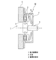
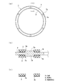
まず、本発明の実施例1に係る乾式摩擦材について、図1及び図2を参照して説明する。図1は本発明の実施例1に係る乾式摩擦材を用いたトルクリミッターの概略構成を示す断面図である。図2(a)は本発明の実施例1に係る乾式摩擦材の全体構成を示す平面図、(b)は(a)のI−I断面を示す縦断面図、(c)は取付け前の摩擦材基材の断面を示す縦断面図である。
Example 1
First, a dry friction material according to Example 1 of the present invention will be described with reference to FIGS. 1 and 2. FIG. 1 is a cross-sectional view showing a schematic configuration of a torque limiter using a dry friction material according to
始めに、実施例1に係る乾式摩擦材が用いられるトルクリミッターについて、図1を参照して説明する。図1に示されるように、本実施の形態に係る乾式摩擦材1は、外径φ220mm×内径φ190mm×厚さ2.4mmのリング状の成形体である摩擦材基材3を、やや大きい外径とやや小さい内径を有する平板リング状の芯金2の両面に取付けてなるものである。トルクリミッター10は、この乾式摩擦材1が押圧される摩擦相手材としての鋼板製のフライホイール5と、乾式摩擦材1と一体に回転する回転軸6を中心にして構成されている。
First, a torque limiter using the dry friction material according to the first embodiment will be described with reference to FIG. As shown in FIG. 1, the
より詳しくは、図1に示されるように、カップリングケース7の中に、鋼板製のプレッシャープレート9と皿ばね8が収納されており、この皿ばね8の付勢力によって、常時プレッシャープレート9が乾式摩擦材1をフライホイール5に押し付けている。これによって、エンジンからの駆動力トルクがフライホイール5から乾式摩擦材1に伝達され、更に乾式摩擦材1と一体に回転する回転軸6によって、トランスミッション側に伝達される。
More specifically, as shown in FIG. 1, a steel plate pressure plate 9 and a disc spring 8 are accommodated in a coupling case 7, and the urging force of the disc spring 8 always causes the pressure plate 9 to be The
すなわち、乾式摩擦材1を構成する摩擦材基材3は、常時芯金2に押し付けられているため、摩擦材基材3は芯金2に固定される必要はなく、摩擦材基材3が芯金2に対してずれないように、位置決めさえされていれば良いことになる。図1に示されるように、鋼板製の芯金2にプレス加工によって設けられた凸部が、上述した方法で製造された摩擦材基材3に設けられた貫通孔に嵌合することによって、かかる位置決めがなされている。
That is, since the
次に、実施例1に係る乾式摩擦材1のより詳細な構造について、図2を参照して説明する。図2(a)に示されるように、本発明の実施例1に係る乾式摩擦材1においては、平板リング形状を有する芯金2の角度60度ごとに、位置決め手段としての合計六箇所の凸部2aが設けられており、平板リング形状を有する摩擦材基材3の角度60度ごとに、位置決め手段としての合計六箇所の貫通孔3aが設けられている。摩擦材基材3の厚さは2.4mmで、凸部2aの突出高さは1.2mm(摩擦材基材3の厚さの50%)である。
Next, a more detailed structure of the
そして、図2(c)に示されるように、取付け前の貫通孔3aは内径が入り口(φ5mm)から奥(φ3mm)に向かって小さくなるテーパー形状を有しており、図2(b)に示されるように、貫通孔3aの入り口の内径とほぼ同じ外径(φ5mm)を有する凸部2aが、貫通孔3aのテーパー形状を押し広げるように嵌合することによって、嵌合部分に拘束力が加わり、より強固な取付けが実現される。
As shown in FIG. 2 (c), the through-
更に、図2(b)に示されるように、2枚の摩擦材基材3の底面には、高摩擦加工としての接着剤コーティング加工3bが施されている。この接着剤コーティング加工は、摩擦材基材3の底面に接着剤を塗布して乾燥させ、軟質層3bを設けるものである。これによって、乾式摩擦材1に掛かる剪断応力によって摩擦材基材3が芯金2に対してずれようとするのを防止できるため、凸部2a及び貫通孔3aに高い応力が掛かって破壊されるような事態を確実に防止することができる。
Further, as shown in FIG. 2B, the bottom surface of the two
実施例2
次に、本発明の実施例2に係る乾式摩擦材について、図3を参照して説明する。図3(a)は本発明の実施例2に係る乾式摩擦材の全体構成を示す平面図、(b)は(a)のA−A断面を示す縦断面図である。
Example 2
Next, a dry friction material according to
本発明の実施例2に係る乾式摩擦材1Aを構成する芯金2A及び摩擦材基材3Aの材質及び製造方法は、上記実施例1に係る乾式摩擦材1と同様である。但し、図3(b)に示されるように、実施例2に係る乾式摩擦材1Aにおいては、芯金2Aの片面のみに摩擦材基材3Aが取付けられる。
The material and manufacturing method of the
図3(a)に示されるように、本発明の実施例2に係る乾式摩擦材1Aにおいては、平板リング形状を有する芯金2Aの角度45度ごとに、位置決め手段としての合計八箇所の凸部2Aaが設けられており、平板リング形状を有する摩擦材基材3Aの角度45度ごとに、位置決め手段としての合計八箇所の貫通孔3Aaが設けられている。摩擦材基材3Aの厚さは2.4mmであり、凸部2Aaの突出高さは2.1mm(摩擦材基材3Cの厚さの87.5%)である。
As shown in FIG. 3A, in the
そして、図3(b)に示されるように、取付け前の貫通孔3Aaは内周が凹凸の連続する波形形状を有し(φ5mm〜φ7mm)、貫通孔3Aaの内周の凹凸のほぼ中間の外径(φ6mm)を有する凸部2Aaが、貫通孔3Aaの内周の凸部分を押し広げるように嵌合することによって、嵌合部分に拘束力が加わり、より強固な取付けが実現される。 As shown in FIG. 3 (b), the through-hole 3Aa before attachment has a corrugated shape in which the inner circumference is continuous with irregularities (φ5 mm to φ7 mm), and is almost in the middle of the irregularities on the inner circumference of the through-hole 3Aa. By fitting the convex portion 2Aa having the outer diameter (φ6 mm) so as to expand the convex portion on the inner periphery of the through-hole 3Aa, a binding force is applied to the fitting portion, thereby realizing a stronger attachment.
実施例3
次に、本発明の実施例3に係る乾式摩擦材について、図4を参照して説明する。図4(a)は本発明の実施例3に係る乾式摩擦材の一部を示す部分平面図、(b)は(a)のB−B断面を示す縦断面図である。
Example 3
Next, a dry friction material according to
本発明の実施例3に係る乾式摩擦材1Bを構成する芯金2B及び摩擦材基材3Bの材質及び製造方法は、上記実施例1に係る乾式摩擦材1と同様である。但し、図4(b)に示されるように、実施例3に係る乾式摩擦材1Bにおいては、芯金2Bの片面のみに摩擦材基材3Bが取付けられる。
The material and manufacturing method of the
本発明の実施例3に係る乾式摩擦材1Bにおいては、平板リング形状を有する芯金2Bの角度45度ごとに、位置決め手段としての合計八箇所の凸部2Baが設けられており、平板リング形状を有する摩擦材基材3Bの角度45度ごとに、位置決め手段としての合計八箇所の貫通孔3Baが設けられている。摩擦材基材3Bの厚さは2.4mmであり、凸部2Baの突出高さは2.0mm(摩擦材基材3Bの厚さの83.3%)である。
In the
そして、図4(a),(b)に示されるように、取付け前の貫通孔3Baは内径がほぼ一定(φ6mm)のストレート孔であり、これに対して凸部2Baは、外周が凹凸の連続する波形形状を有している(φ5mm〜φ7mm)。したがって、両者が嵌合することによって、貫通孔3Baの内周が凸部2Baの外周の凸部分によって押し広げられるように嵌合して、嵌合部分に拘束力が加わり、より強固な取付けが実現される。 As shown in FIGS. 4A and 4B, the through-hole 3Ba before mounting is a straight hole having a substantially constant inner diameter (φ6 mm), whereas the convex portion 2Ba has an uneven outer periphery. It has a continuous wave shape (φ5 mm to φ7 mm). Therefore, when both are fitted, the fitting is performed so that the inner circumference of the through hole 3Ba is pushed and expanded by the convex portion on the outer circumference of the convex portion 2Ba. Realized.
実施例4
次に、本発明の実施例4に係る乾式摩擦材について、図5を参照して説明する。図5(a)は本発明の実施例4に係る乾式摩擦材の一部を示す部分平面図、(b)は(a)のC−C断面を示す縦断面図である。
Example 4
Next, a dry friction material according to
本発明の実施例4に係る乾式摩擦材1Cを構成する芯金2C及び摩擦材基材3Cの材質及び製造方法は、上記実施例1に係る乾式摩擦材1と同様である。但し、図5(b)に示されるように、実施例4に係る乾式摩擦材1Cにおいては、芯金2Cの片面のみに摩擦材基材3Cが取付けられる。
The material and manufacturing method of the
本発明の実施例4に係る乾式摩擦材1Cにおいては、平板リング形状を有する芯金2Cの角度60度ごとに、位置決め手段としての合計六箇所の凸部2Caが設けられており、平板リング形状を有する摩擦材基材3Cの角度60度ごとに、位置決め手段としての合計六箇所の貫通孔3Caが設けられている。摩擦材基材3Cの厚さは2.4mmであり、凸部2Caの突出高さは2.0mm(摩擦材基材3Cの厚さの83.3%)である。
In the
そして、図5(a),(b)に示されるように、貫通孔3Caは内径が二段に変化しており、入り口側(芯金2C側)の内径の大きい部分には、合成ゴム製のOリング4がセットされている。これに対して、凸部2Caは、外径がほぼ一定でOリング4の内径よりやや大きい、ストレートな円柱形状を有している。したがって、凸部2Caが貫通孔3Caに嵌合することによって、凸部2CaがOリング4によって拘束され、より強固な取付けが実現される。
As shown in FIGS. 5A and 5B, the inner diameter of the through hole 3Ca is changed in two steps, and a portion having a larger inner diameter on the entrance side (
実施例5
次に、本発明の実施例5に係る乾式摩擦材について、図6を参照して説明する。図6(a)は本発明の実施例5に係る乾式摩擦材の全体構成を示す平面図、(b)は(a)のD−D断面を示す縦断面図である。
Example 5
Next, a dry friction material according to Embodiment 5 of the present invention will be described with reference to FIG. FIG. 6A is a plan view showing an overall configuration of a dry friction material according to Embodiment 5 of the present invention, and FIG. 6B is a longitudinal sectional view showing a DD section of FIG.
本発明の実施例5に係る乾式摩擦材1Dを構成する芯金2D及び摩擦材基材3Dの材質及び製造方法は、上記実施例1に係る乾式摩擦材1と同様である。また、図6(b)に示されるように、実施例5に係る乾式摩擦材1Dにおいては、上記実施例1に係る乾式摩擦材1と同様に、芯金2Dの両面に摩擦材基材3Dが取付けられる。
The material and manufacturing method of the
図6(a)に示されるように、本発明の実施例5に係る乾式摩擦材1Dにおいては、平板リング形状を有する芯金2Dの角度45度ごとに、位置決め手段としての合計八箇所の凸部2Daが設けられており、平板リング形状を有する摩擦材基材3Dの角度45度ごとに、位置決め手段としての合計八箇所の貫通孔3Daが設けられている。摩擦材基材3Dの厚さは2.4mmであり、凸部2Daの突出高さは2.0mm(摩擦材基材3Dの厚さの83.3%)である。
As shown in FIG. 6A, in the
そして、図6(a),(b)に示されるように、貫通孔3Daは内径がほぼ一定のストレート孔であり、凸部2Daも外径がほぼ一定のストレートな円柱形状を有しているが、凸部2Daの中心軸2Dbは、貫通孔3Daの中心軸3Dbよりも外周側に位置するようにずれている。したがって、八箇所の凸部2Daが八箇所の貫通孔3Daに嵌合することによって、貫通孔3Daが凸部2Daの側の中心位置に合わせて伸張して嵌合することになり、摩擦材基材3Dの全周に亘って均等に伸張力が加わり、より強固な取付けを実現することができる。
6A and 6B, the through hole 3Da is a straight hole having a substantially constant inner diameter, and the convex portion 2Da has a straight cylindrical shape having a substantially constant outer diameter. However, center axis 2Db of convex part 2Da has shifted so that it may be located in the perimeter side rather than center axis 3Db of through-hole 3Da. Therefore, when the eight convex portions 2Da are fitted into the eight through holes 3Da, the through holes 3Da are extended and fitted in accordance with the center position on the convex portion 2Da side, and the friction material base A stretching force is evenly applied over the entire circumference of the
実施例6
次に、本発明の実施例6に係る乾式摩擦材について、図7を参照して説明する。図7(a)は本発明の実施例6に係る乾式摩擦材の全体構成を示す平面図、(b)は(a)のE−E断面を示す縦断面図である。
Example 6
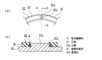
Next, a dry friction material according to Embodiment 6 of the present invention will be described with reference to FIG. FIG. 7A is a plan view showing an overall configuration of a dry friction material according to Example 6 of the present invention, and FIG. 7B is a longitudinal sectional view showing an EE cross section of FIG.
本発明の実施例6に係る乾式摩擦材1Eを構成する芯金2E及び摩擦材基材3Eの材質及び製造方法は、上記実施例1に係る乾式摩擦材1と同様である。但し、図7(b)に示されるように、実施例6に係る乾式摩擦材1Eにおいては、芯金2Eの片面のみに摩擦材基材3Eが取付けられる。
The material and manufacturing method of the
図7(a),(b)に示されるように、本発明の実施例6に係る乾式摩擦材1Eにおいては、摩擦材基材3Eの外周側面及び内周側面に位置決め手段としてのテーパー(垂線に対して約20度、すなわち底面に対して約70度)が設けられており、平板リング形状を有する芯金2Eの角度90度ごとに、位置決め手段としての合計四箇所のフック2Eaが設けられている。摩擦材基材3Eの厚さは2.5mmであり、フック2Eaの突出高さは2.0mm(摩擦材基材3Eの厚さの80%)である。
As shown in FIGS. 7A and 7B, in the
そして、図6(b)に示されるように、フック2Eaの外周面は、摩擦材基材3Eの内周側面のテーパーに係合するように傾斜している。したがって、平板リング形状を有する摩擦材基材3Eをやや変形させながら、内周側面のテーパーを四箇所のフック2Eaに係合させることによって、摩擦材基材3Eを芯金2Eに対して位置決めすることができ、極めて容易に取付けを行うことができる。
And as FIG.6 (b) shows, the outer peripheral surface of hook 2Ea inclines so that it may engage with the taper of the inner peripheral side surface of the friction
実施例7
次に、本発明の実施例7に係る乾式摩擦材について、図8を参照して説明する。図8(a)は本発明の実施例7に係る乾式摩擦材の全体構成を示す平面図、(b)は(a)のF−F断面を示す縦断面図である。
Example 7
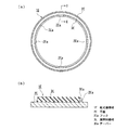
Next, a dry friction material according to Embodiment 7 of the present invention will be described with reference to FIG. FIG. 8A is a plan view showing the overall configuration of the dry friction material according to Example 7 of the present invention, and FIG. 8B is a longitudinal sectional view showing the FF section of FIG.
本発明の実施例7に係る乾式摩擦材1Fを構成する芯金2F及び摩擦材基材3Fの材質及び製造方法は、上記実施例1に係る乾式摩擦材1と同様である。また、図8(b)に示されるように、実施例7に係る乾式摩擦材1Fにおいては、上記実施例1に係る乾式摩擦材1と同様に、芯金2Fの両面に摩擦材基材3Fが取付けられる。
The material and manufacturing method of the
図8(a),(b)に示されるように、本発明の実施例7に係る乾式摩擦材1Fにおいては、芯金2Fの両面の、摩擦材基材3Fの外周側面及び内周側面に接する位置に、位置決め手段としての位置決めピン2Faが設けられており、これらの位置決めピン2Faは、平板リング形状を有する芯金2Eの角度45度ごとに2本ずつ、合計16本設けられている。摩擦材基材3Fの厚さは2.5mmであり、位置決めピン2Faの突出高さは1.3mm(摩擦材基材3Fの厚さの52%)である。
As shown in FIGS. 8A and 8B, in the
したがって、平板リング形状を有する摩擦材基材3Fをこれらの16本の位置決めピン2Faの間に嵌め込むことによって、摩擦材基材3Fが芯金2Fに対して正確に位置決めされ、取付けることができることから、取付けが非常に容易になるとともに工数も減少する。
Therefore, by fitting the
更に、図8(b)に示されるように、2枚の摩擦材基材3Fの底面には、高摩擦加工としての軟質ゴムの層を設けるゴムコーティング加工3Faが施されていることから、乾式摩擦材1Fに掛かる剪断応力によって摩擦材基材3Fが芯金2Fに対してずれるのを防止できるため、位置決めピン2Faの間において、摩擦材基材3Fが剪断応力によって回転する事態を防ぐことができる。
Further, as shown in FIG. 8B, the bottom surface of the two
上記各実施例においては、芯金に凸部を設けて、摩擦材基材に貫通孔を設けた場合のみについて説明したが、貫通孔を設けるのと同様にして摩擦材基材に凹部を設けることもでき、また上述したように、摩擦材基材に凸部を設けて、芯金に凹部若しくは貫通孔を設けることも可能である。 In each of the above-described embodiments, only the case where the core metal is provided with the convex portion and the friction material base material is provided with the through hole has been described. However, the friction material base material is provided with the concave portion similarly to the case where the through hole is provided. In addition, as described above, it is also possible to provide a convex portion on the friction material base and to provide a concave portion or a through hole on the core metal.
本発明を実施するに際しては、乾式摩擦材のその他の部分の形状、大きさ、材質、組成、成分、配合量、製造方法等についても、上記各実施例に限定されるものではない。なお、本発明の実施の形態及び各実施例で挙げている数値は、その全てが臨界値を示すものではなく、ある数値は実施に好適な好適値を示すものであるから、上記数値を若干変更してもその実施を否定するものではない。 In practicing the present invention, the shape, size, material, composition, component, blending amount, manufacturing method, and the like of other portions of the dry friction material are not limited to the above embodiments. It should be noted that the numerical values given in the embodiment and each example of the present invention are not all critical values, and certain numerical values indicate preferred values suitable for implementation. Changing it does not deny its implementation.
1,1A,1B,1C,1D,1E,1F 乾式摩擦材
2,2A,2B,2C,2D,2E,2F 芯金
2a,2Aa,2Ba,2Ca,2Da 凸部
2Ea フック
2Fa 位置決めピン
3,3A,3B,3C,3D,3E,3F 摩擦材基材
3a,3Aa,3Ba,3Ca,3Da 貫通孔
3b,3Fa 高摩擦加工
3Ea テーパー
1, 1A, 1B, 1C, 1D, 1E, 1F
Claims (9)
前記摩擦材基材は常時前記芯金に押し付けられており、
前記芯金及び/または前記摩擦材基材には、前記摩擦材基材を前記芯金に対して同芯に位置決めするための位置決め手段が設けられたことを特徴とする乾式摩擦材。 A dry friction material in which a flat ring-shaped friction material base is attached to one or both sides of a flat ring-shaped cored bar,
The friction material base is always pressed against the cored bar,
A dry friction material, wherein the core metal and / or the friction material base material is provided with positioning means for positioning the friction material base material concentrically with the core metal.
Priority Applications (1)
| Application Number | Priority Date | Filing Date | Title |
|---|---|---|---|
| JP2009070024A JP2010223294A (en) | 2009-03-23 | 2009-03-23 | Dry-type frictional material |
Applications Claiming Priority (1)
| Application Number | Priority Date | Filing Date | Title |
|---|---|---|---|
| JP2009070024A JP2010223294A (en) | 2009-03-23 | 2009-03-23 | Dry-type frictional material |
Publications (2)
| Publication Number | Publication Date |
|---|---|
| JP2010223294A true JP2010223294A (en) | 2010-10-07 |
| JP2010223294A5 JP2010223294A5 (en) | 2011-01-20 |
Family
ID=43040709
Family Applications (1)
| Application Number | Title | Priority Date | Filing Date |
|---|---|---|---|
| JP2009070024A Pending JP2010223294A (en) | 2009-03-23 | 2009-03-23 | Dry-type frictional material |
Country Status (1)
| Country | Link |
|---|---|
| JP (1) | JP2010223294A (en) |
Cited By (2)
| Publication number | Priority date | Publication date | Assignee | Title |
|---|---|---|---|---|
| CN109268415A (en) * | 2018-11-28 | 2019-01-25 | 徐州顺达钢轮制造有限公司 | A kind of brake block with auxiliary assembling function |
| US10208807B2 (en) * | 2011-06-06 | 2019-02-19 | Toyota Jidosha Kabushiki Kaisha | Torque-limiting device for vehicle |
Citations (3)
| Publication number | Priority date | Publication date | Assignee | Title |
|---|---|---|---|---|
| JPS6034519A (en) * | 1983-04-19 | 1985-02-22 | ヴアレオ | Clutch disc |
| JPH0413831U (en) * | 1990-05-24 | 1992-02-04 | ||
| JP2000153767A (en) * | 1998-09-18 | 2000-06-06 | Mitsuba Corp | Power steering apparatus |
-
2009
- 2009-03-23 JP JP2009070024A patent/JP2010223294A/en active Pending
Patent Citations (3)
| Publication number | Priority date | Publication date | Assignee | Title |
|---|---|---|---|---|
| JPS6034519A (en) * | 1983-04-19 | 1985-02-22 | ヴアレオ | Clutch disc |
| JPH0413831U (en) * | 1990-05-24 | 1992-02-04 | ||
| JP2000153767A (en) * | 1998-09-18 | 2000-06-06 | Mitsuba Corp | Power steering apparatus |
Cited By (2)
| Publication number | Priority date | Publication date | Assignee | Title |
|---|---|---|---|---|
| US10208807B2 (en) * | 2011-06-06 | 2019-02-19 | Toyota Jidosha Kabushiki Kaisha | Torque-limiting device for vehicle |
| CN109268415A (en) * | 2018-11-28 | 2019-01-25 | 徐州顺达钢轮制造有限公司 | A kind of brake block with auxiliary assembling function |
Similar Documents
| Publication | Publication Date | Title |
|---|---|---|
| JP3642734B2 (en) | Method for manufacturing plastic pulley with metal insert | |
| US7682256B2 (en) | Flange design for filament wound composite shaft | |
| JP6824704B2 (en) | Stabilizer bush | |
| JP2012102755A (en) | Torque limiter for vehicle | |
| WO1999022153A1 (en) | Elastomeric bearing and assembly method therefor | |
| JP6835545B2 (en) | Stabilizer bush | |
| JP2010223294A (en) | Dry-type frictional material | |
| JP2010223294A5 (en) | ||
| JP5214061B2 (en) | Dry friction material and manufacturing method thereof | |
| JP2007071263A (en) | Torque fluctuation absorbing damper | |
| JP6680696B2 (en) | Manufacturing method of gear having reinforcing ring | |
| US7963853B2 (en) | Filament wound composite shaft | |
| JP4149449B2 (en) | Method of covering and joining urethane coating to metal wire | |
| JP2001270315A (en) | Stabilizer bar with rubber bush | |
| JP6104614B2 (en) | Dynamic damper | |
| JP2005188638A (en) | Power transmission device | |
| JP6089719B2 (en) | Dynamic damper | |
| JP2006194265A (en) | Torque fluctuation absorbing damper | |
| JP2019152254A (en) | Method for manufacturing spring for suspension device | |
| JP4859940B2 (en) | Dry friction material | |
| JP5639582B2 (en) | Low torque shaft seal and its construction method | |
| JPS60132736A (en) | Preparation of vibration proof rubber with metal housing | |
| JPH1026182A (en) | Coil spring assembly and damper mechanism | |
| JPS60141533A (en) | Manufacture of rubber spring with metal housing | |
| JP4466899B2 (en) | Disc loading roll |
Legal Events
| Date | Code | Title | Description |
|---|---|---|---|
| A521 | Written amendment |
Free format text: JAPANESE INTERMEDIATE CODE: A523 Effective date: 20101129 |
|
| A621 | Written request for application examination |
Effective date: 20101129 Free format text: JAPANESE INTERMEDIATE CODE: A621 |
|
| A131 | Notification of reasons for refusal |
Free format text: JAPANESE INTERMEDIATE CODE: A131 Effective date: 20111213 |
|
| A977 | Report on retrieval |
Effective date: 20111215 Free format text: JAPANESE INTERMEDIATE CODE: A971007 |
|
| A02 | Decision of refusal |
Free format text: JAPANESE INTERMEDIATE CODE: A02 Effective date: 20120410 |