JP2010218663A - Head slider and magnetic storage device - Google Patents
Head slider and magnetic storage device Download PDFInfo
- Publication number
- JP2010218663A JP2010218663A JP2009066911A JP2009066911A JP2010218663A JP 2010218663 A JP2010218663 A JP 2010218663A JP 2009066911 A JP2009066911 A JP 2009066911A JP 2009066911 A JP2009066911 A JP 2009066911A JP 2010218663 A JP2010218663 A JP 2010218663A
- Authority
- JP
- Japan
- Prior art keywords
- head slider
- end surface
- recording medium
- magnetic recording
- outflow end
- Prior art date
- Legal status (The legal status is an assumption and is not a legal conclusion. Google has not performed a legal analysis and makes no representation as to the accuracy of the status listed.)
- Pending
Links
Images


Classifications
-
- G—PHYSICS
- G11—INFORMATION STORAGE
- G11B—INFORMATION STORAGE BASED ON RELATIVE MOVEMENT BETWEEN RECORD CARRIER AND TRANSDUCER
- G11B5/00—Recording by magnetisation or demagnetisation of a record carrier; Reproducing by magnetic means; Record carriers therefor
- G11B5/48—Disposition or mounting of heads or head supports relative to record carriers ; arrangements of heads, e.g. for scanning the record carrier to increase the relative speed
- G11B5/58—Disposition or mounting of heads or head supports relative to record carriers ; arrangements of heads, e.g. for scanning the record carrier to increase the relative speed with provision for moving the head for the purpose of maintaining alignment of the head relative to the record carrier during transducing operation, e.g. to compensate for surface irregularities of the latter or for track following
- G11B5/60—Fluid-dynamic spacing of heads from record-carriers
- G11B5/6005—Specially adapted for spacing from a rotating disc using a fluid cushion
Landscapes
- Adjustment Of The Magnetic Head Position Track Following On Tapes (AREA)
Abstract
Description
本発明は、ヘッドスライダおよび磁気記憶装置に関する。 The present invention relates to a head slider and a magnetic storage device.
近年では、磁気記憶装置に設けた磁気ヘッド(ヘッドスライダ)の浮上面と磁気記録媒体との距離(ヘッドスライダの浮上量)は、高記録密度化の要求から、より小さくすることが要求されている。具体的には、このような磁気ヘッドを搭載したヘッドスライダの最小浮上量は既に数nm以下にまで達している。 In recent years, the distance between the flying surface of the magnetic head (head slider) provided in the magnetic storage device and the magnetic recording medium (the flying height of the head slider) has been required to be smaller due to the demand for higher recording density. Yes. Specifically, the minimum flying height of a head slider equipped with such a magnetic head has already reached several nm or less.
ところが、このように、ヘッドスライダの浮上量を微少とすると、磁気記録媒体の表面に設けられた潤滑層を形成する潤滑剤が、ヘッドスライダに付着するという問題が発生する。 However, as described above, when the flying height of the head slider is made small, there arises a problem that the lubricant forming the lubricating layer provided on the surface of the magnetic recording medium adheres to the head slider.
以下、図7を用いて、このヘッドスライダの浮上量に関する問題点ついて説明する。図7は、従来のヘッドスライダの概要を示す側面図である。図7に示すように、サスペンション8に支持されたヘッドスライダ7の底面(浮上面9)と磁気記録媒体2との間は、空気流の流動により微小量浮上している。
Hereinafter, the problem relating to the flying height of the head slider will be described with reference to FIG. FIG. 7 is a side view showing an outline of a conventional head slider. As shown in FIG. 7, a slight amount of flying is caused between the bottom surface (floating surface 9) of the
ここで、磁気記録媒体2の表面部には、この磁気記録媒体2とヘッドスライダ7との摩擦を低減するための潤滑剤が塗布されている。このため、磁気記録媒体2の回転時に気化した潤滑剤がヘッドスライダ7の底面部(浮上面9)に付着し、付着した潤滑剤が蓄積して液滴となって磁気記録媒体2上に落下することとなる。
Here, a lubricant for reducing friction between the
すなわち、図7に示すように、ヘッドスライダ7と磁気記録媒体2との間には、磁気記録媒体2の回転により空気流が発生している。この空気流は、ヘッドスライダの上流側から下流側に流れるため、下流側のヘッドスライダ7の浮上面9から垂直方向に延在する端面(以下、「流出端面9a」と言う)上に潤滑剤が移動し堆積する。そして、このように、ヘッドスライダ7の流出端面9aに潤滑剤が堆積した場合、潤滑剤がある程度の塊となって磁気記録媒体2上に落下する。
That is, as shown in FIG. 7, an air flow is generated between the
そして、このように流出端面9aに堆積した潤滑剤の塊が磁気記録媒体2上に落下した場合には、磁気記録媒体2の表面が汚染されると共に、この潤滑剤の塊がヘッドスライダ7の安定な浮上を阻害したり、ヘッドスライダ7に設けた磁気ヘッドにダメージを与えてしまうという問題が発生する。
When the lubricant lump deposited on the outflow end surface 9a falls on the
そこで、上述したような問題を解決すべく、従来技術として、ヘッドスライダと磁気記録媒体が相対する媒体対向面に硬化樹脂を塗布し、媒体対向面を多孔質化させることにより潤滑剤を保持するヘッドスライダに関するものが開示されている(特許文献1参照)。 In order to solve the above-described problems, as a conventional technique, a hardened resin is applied to the medium facing surface where the head slider and the magnetic recording medium face each other, and the lubricant is held by making the medium facing surface porous. The thing regarding a head slider is disclosed (refer patent document 1).
ところが、上述した従来のヘッドスライダの場合には、以下に示す問題がある。すなわち、特許文献1に記載されたヘッドスライダでは、ヘッドスライダの媒体対向面(浮上面)に硬化樹脂が成膜されて形成されている。 However, the conventional head slider described above has the following problems. That is, the head slider described in Patent Document 1 is formed by forming a cured resin film on the medium facing surface (floating surface) of the head slider.
ところが、このように、ヘッドスライダの浮上面に硬化樹脂を成膜した場合には、ヘッドスライダの浮上特性に悪影響を与えることとなる。また、媒体対向面を介して、ヘッドスライダの媒体対向面から流出端面に近い部分に潤滑剤が移着した場合、この移着した潤滑剤の塊りなどは、ヘッドスライダ上に保持することが困難になる。これにより、ヘッドスライダの汚染や磁気ヘッドに対してダメージが生じたり、ヘッドスライダの浮上の安定性を維持できないという問題が発生する。 However, when the cured resin is formed on the flying surface of the head slider in this way, the flying characteristics of the head slider are adversely affected. Further, when the lubricant is transferred to the portion close to the outflow end surface from the medium facing surface of the head slider via the medium facing surface, the lump of the transferred lubricant can be held on the head slider. It becomes difficult. This causes problems such as contamination of the head slider, damage to the magnetic head, and inability to maintain the flying stability of the head slider.
そこで、この発明は、上述した従来技術の課題を解決するためになされたものであり、磁気記録媒体からヘッドスライダに付着した潤滑剤の落下の防止とともに、ヘッドスライダの浮上時の安定性を維持することができるヘッドスライダおよび磁気記憶装置を提供することを目的とする。 Accordingly, the present invention has been made to solve the above-mentioned problems of the prior art, and prevents the lubricant attached to the head slider from dropping from the magnetic recording medium and maintains the stability of the head slider when it floats. It is an object of the present invention to provide a head slider and a magnetic storage device that can be used.
開示の磁気記憶装置に備えたヘッドスライダは、流入端面から媒体対向面を通して空気流が導かれる流出端面と、媒体対向面の両側に位置する側面と、流出端面又は/及び側面に設けられた空気流とともに導かれる流動物質を吸着させる吸着構造とを備えたことを要件とする。 The head slider provided in the disclosed magnetic storage device includes an outflow end surface through which an air flow is guided from the inflow end surface through the medium facing surface, side surfaces located on both sides of the medium facing surface, and air provided on the outflow end surface and / or side surfaces. It is necessary to have an adsorption structure for adsorbing a fluid substance guided along with the flow.
開示の磁気記憶装置に備えたヘッドスライダは、ヘッドスライダの流出端面に、媒体対向面に付着した潤滑剤を吸着し保持する吸着構造を設けているので、ヘッドスライダに付着した潤滑剤はヘッドスライダ上を流れても塊となって磁気記録媒体に落下することを防止することができ、これによって、磁気記録媒体に対する汚染やヘッドスライダの浮上に対する悪影響を防止し、安定性を向上することができる。 Since the head slider provided in the disclosed magnetic storage device is provided with an adsorption structure that adsorbs and holds the lubricant adhering to the medium facing surface on the outflow end surface of the head slider, the lubricant adhering to the head slider is Even if it flows above, it can be prevented from falling into a lump on the magnetic recording medium, thereby preventing the magnetic recording medium from being contaminated and the head slider flying up, and improving the stability. .
以下に添付図面を参照して、本願の開示するヘッドスライダおよび磁気記憶装置の好適な実施の形態を詳細に説明する。なお、この実施例1により本願に開示するヘッドスライダおよび磁気記憶装置が限定されるものではない。 Exemplary embodiments of a head slider and a magnetic storage device disclosed in the present application will be described below in detail with reference to the accompanying drawings. The head slider and the magnetic storage device disclosed in the present application are not limited to the first embodiment.
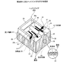
先ず、実施例1に係る磁気記憶装置1の概要について説明する。図1は、実施例1に係る磁気記憶装置の内部を示す外観図である。図1に示すように、磁気記憶装置1は、磁気記録媒体2と、サスペンション3に支持されたヘッドスライダ20とスピンドルモータ(以下、「SPM」という)4とを有する。また、サスペンション3(ヘッドスライダ20)の駆動機構であるボイスコイルモータ(以下、「VCM」という)5とを有する。
First, an outline of the magnetic storage device 1 according to the first embodiment will be described. FIG. 1 is an external view of the inside of the magnetic storage device according to the first embodiment. As shown in FIG. 1, the magnetic storage device 1 includes a
磁気記録媒体2は、各種の磁気情報を高記録密度に記録する磁気記憶媒体であり、SPM4により所定の方向(図1では、反時計方向)に回転駆動される。
The
サスペンション3に支持されたヘッドスライダ20の先端部には、磁気記録媒体2に記録された磁気情報の読み書きを行なうための磁気ヘッド10が設けられている。
A
VCM5は、磁気ヘッド10の位置および速度を制御する。具体的には、VCMドライバ16(図6)から供給される電流に基づいて磁気ヘッド10の速度を加速したり、磁気ヘッド10の作動を停止させたりする。
The VCM 5 controls the position and speed of the
以上説明した磁気記憶装置1において、ヘッドスライダ20の先端部に設けられた磁気ヘッド10はVCM5の駆動により、サスペンション3が軸部6を中心とする円弧上を回動することで、磁気記録媒体2のトラック横断方向にシーク移動し、読み書き対象となるトラックを変更する。そして、磁気記録媒体2のトラック幅方向にヘッドスライダ20に設けられた磁気ヘッド10を移動させることで読み書き対象となるトラックを変更する。
In the magnetic storage device 1 described above, the
磁気ヘッド10は、磁気記録媒体2の回転によって生じる揚力によって、磁気記録媒体2の表面から僅かに浮上した状態を維持しつつ、読み書き対象となるトラックまで移動し、リード処理及びライト処理(データの読み書き処理)を行う。
The
[ヘッドスライダの浮上面]
次に、図2を用いて、本実施例1に係るヘッドスライダの形状の詳細について説明する。図2は、本実施例1に係るヘッドスライダを示す斜視図である。ここで、図2中の白矢印は、ヘッドスライダに流れる空気流の方向を示している。また、黒矢印は、磁気記録媒体を介してヘッドスライダに付着した潤滑剤が流れる方向を示している。
[Floating surface of head slider]
Next, details of the shape of the head slider according to the first embodiment will be described with reference to FIG. FIG. 2 is a perspective view illustrating the head slider according to the first embodiment. Here, the white arrows in FIG. 2 indicate the direction of the airflow flowing through the head slider. A black arrow indicates the direction in which the lubricant attached to the head slider flows through the magnetic recording medium.
図2に示すように、ヘッドスライダ20は、全体が略四角型に形成されたヘッドスライダ本体部21を備えており、スライダ本体部21は、磁気記録媒体2(図1)に対向する対向面22と、空気流が流入する流入端面23と、空気流が流出する流出端面24とが形成されている。
As shown in FIG. 2, the
ここで、図2に示している磁気記録媒体2に対向する対向面22が浮上面となる。また、このヘッドスライダ20の対向面22の側方(左右位置)には、一対の側端面25が形成されている。
Here, the facing surface 22 facing the
また、同図に示すように、ヘッドスライダ20の浮上面となる対向面22には、この対向面22から隆起するセンターパッド部26および一対のサイドパッド部27と、全体がコ字型で一対のサイド面28および仕切り板28aを有する流入側突部29とが形成されている。センターパッド部27は、流出端面24側の幅方向中央に配置された隆起部であり、このセンターパッド部27の先端部には磁気ヘッド10(図1)が固設されている。
Further, as shown in the figure, the opposing surface 22 which is the air bearing surface of the
サイドパッド部27は、センターパッド部26の一部を挟み込むように配置された隆起部であり、サイドパッド部27とセンターパッド部26との間に形成された2箇所の隙間32から潤滑材を流出させることができる。
The
流入側突部29は、ヘッドスライダ20の流入端面23側に設けられた隆起部であり、流入端面23から流れ込む空気流を対向面22を通じて流出端面24に向けて誘導する。
The
ここで、流入側突部29を形成する一対のサイド面28と仕切り板28aとで囲まれた対向面22の領域は、負圧領域28bとなっており、この負圧領域28bは、ヘッドスライダ20が磁気記録媒体2上を高速移動する際に生じる気流を受けて、ヘッドスライダ20を磁気記録媒体2から離隔させる方向、すなわち浮上量を大きくする方向の圧力を生じさせる領域として形成されている。
Here, a region of the facing surface 22 surrounded by the pair of side surfaces 28 and the
このように、ヘッドスライダ20の浮上面(対向面22)は、センターパッド部26と一対のサイドパッド部27と、コ字型のサイド面28を有する流入側突部29との3箇所の隆起部を形成することで、ヘッドスライダ20の対向面22(浮上面)に対して、空気流により作用する剪断応力が一点に集中する領域が存在しない形状となっている。具体的には、対向面22に潤滑剤が蓄積し難い形状として形成されている。
As described above, the air bearing surface (opposing surface 22) of the
さらに、このヘッドスライダ20の対向面22の形状は、流入端面23側よりも流出端面24に向かうほど対向面22の高さ(傾斜)が低くなるように形成されている。具体的には、ヘッドスライダ20の対向面22から流出端面24に向かって不要な流動物質である潤滑剤の流れが促進されるように、対向面22の形状が傾斜部となるように形成している。
Furthermore, the shape of the facing surface 22 of the
これにより、ヘッドスライダ20の対向面22の付着した潤滑剤を流動物質の排出側である流出端面24に向けて効率よく導くことができる。
Thereby, the lubricant adhering to the facing surface 22 of the
そして、本実施例1のヘッドスライダ20では、このヘッドスライダ20の対向面22を形成する空気流が流出する流出端面24に、磁気記録媒体2を介して対向面22に付着した潤滑剤を吸着し保持することができる多孔質成膜部30を設けている。
In the
すなわち、図1に示すように、ヘッドスライダ20の流出端面24の表面部には、この流出端面24の全面を覆うように多孔質のセラミックス系の膜体が成膜により形成されている。このように流出端面24に成膜する多孔質のセラミックス系の膜体としては、ポーラスシリカ、ポーラスアルミナ、ポリエチレン粒子などが使用される。
That is, as shown in FIG. 1, a porous ceramic film body is formed on the surface of the outflow end face 24 of the
ここで、図2に示すヘッドスライダ20を製造する場合、このヘッドスライダ20の対向面22(浮上面)の加工は、ミリングやエッチングなどで行なう。具体的には、対向面22に形成する部材をそれぞれ形成する度に、レジスト塗布、フォトリソグラフィーによるレジスト加工、ミリングやエッチングによる対象物の加工、レジスト除去などの一連の製造作業を行なう。
Here, when the
また、ヘッドスライダ20の流出端面24にポーラスシリカなどの多孔質成膜部30を塗布や蒸着法により成膜する場合には、ヘッドスライダ20を製造する時に使用する基板の製造時とほぼ同時又は、基板の製造後に行なう。
Further, when the porous
また、本実施例1では、ヘッドスライダ20の対向面22の側方に位置する一対の側端面25にも、これら側端面25の全面を覆うように多孔質のセラミックス系の膜体が多孔質成膜部31として形成されている。
In the first embodiment, a porous ceramic film body is also porous on the pair of side end surfaces 25 located on the side of the facing surface 22 of the
そして、図1に示すように、本実施例1に係るヘッドスライダ20では、対向面22に付着した潤滑剤のうち、対向面22から直進するように誘導される潤滑剤は、この対向面22からセンターパッド部26とサイドパッド部27との2箇所の間隙32を通じて、流出端面24に設けた多孔質成膜部30により吸着され保持される。
As shown in FIG. 1, in the
具体的には、多孔質成膜部30に付着した潤滑剤は、多孔質成膜部30を形成する複数個の空孔30aに染み込むことで、これら複数の空孔30aの内部に保持される。
Specifically, the lubricant adhering to the porous
また、対向面22の横方向に誘導される潤滑剤は、この対向面22からセンターパッド部26とサイドパッド部27との2箇所の間隙33を通じて、側端面25に設けた多孔質成膜部31により吸着され保持される。
In addition, the lubricant guided in the lateral direction of the facing surface 22 passes through the
本実施例1に係るヘッドスライダ20によれば、スライダ20の空気流が流出する流出端面24および側端面25の全面には多孔質成膜部30、31が形成されているので、磁気記録媒体2を介してヘッドスライダ20の対向面22に付着した潤滑剤を多孔質成膜部30、31により効率よく吸着するとともに保持することができる。
According to the
これによって、ヘッドスライダ20の対向面22に付着した潤滑剤を円滑な状態で吸い上げるとともに保持することができるため、潤滑剤の溜りを無くすことが可能となるとともに、吸着した潤滑剤を保持することによりこの潤滑剤が磁気記録媒体2に落下することを確実に防止することができる。
As a result, the lubricant adhering to the facing surface 22 of the
次に、本実施例2に係るヘッドスライダ20Aの全体形状について説明する。図3は、本実施例2に係るヘッドスライダ20Aを示す斜視図である。ここで、前述した実施例1のヘッドスライダ20と同一の部材を示す符号の説明については、形状および機能が同一なため詳細な説明は省略する。
Next, the overall shape of the
図3に示すように、実施例2に係るヘッドスライダ20Aは、全体が略四角型に形成されたスライダ本体部21を備えている。また、ヘッドスライダ20Aの本体部21は、磁気記録媒体2に対する対向面22と、空気流が流入する流入端面23と、空気流が流出する流出端面24と対向面22の側方(左右位置)に位置する一対の側端面25とにより形成されている。
As shown in FIG. 3, the
そして、この本実施例2に係るヘッドスライダ20Aでは、空気流が流出する流出端面24には、この流出端面24の全面を覆うように長繊維部材40が貼り付け固定されている。長繊維部材40には、親油性の薬液を塗布した不織布などを用いる。
In the
すなわち、このように、長繊維部材40に親油性の薬液を塗布した不織布などを用いることで、潤滑剤の染み込みの促進および長繊維部材40による潤滑剤の保持を容易且つ確実に行なうことができる。
That is, by using a nonwoven fabric or the like in which the
また、本実施例2では、前記実施例1と同様に、ヘッドスライダ20の対向面22の側方に位置する一対の側端面25にも、これら側端面25の全面を覆うように長繊維部材41が貼り付け固定されている。
In the second embodiment, similarly to the first embodiment, the pair of side end surfaces 25 located on the side of the facing surface 22 of the
そして、図3に示すように、本実施例2に係るヘッドスライダ20Aでは、対向面22に付着した潤滑剤のうち、対向面22から直進するように誘導される潤滑剤は、この対向面22からセンターパッド部26とサイドパッド部27との2箇所の間隙32を通じて、流出端面24に設けた長繊維部材40により吸着され保持される。
As shown in FIG. 3, in the
また、対向面22の横方向に誘導される潤滑剤は、この対向面22からセンターパッド部26とサイドパッド部27との2箇所の間隙33を通じて、側端面25に設けた長繊維部材41により吸着され保持される。
Further, the lubricant guided in the lateral direction of the facing surface 22 is caused by the
本実施例2に係るヘッドスライダ20Aでは、ヘッドスライダ20Aの空気流が流出する流出端面24および側端面25の全面には長繊維部材40、41が貼り付け固定されている。
In the
これにより、磁気記録媒体2を介してヘッドスライダ20の対向面22に付着した潤滑剤を長繊維部材40、41により効率よく吸着するとともに保持することで潤滑剤の溜りを無くすことが可能となるとともに、磁気記録媒体2に対する潤滑剤の落下を確実に防止することができる。
As a result, the lubricant adhering to the facing surface 22 of the
次に、本実施例3に係るヘッドスライダ20Bの全体形状について説明する。図4は、本実施例3に係るヘッドスライダ20Bの浮上面を示す斜視図である。ここで、前述した実施例2のヘッドスライダ20Aと同一の部材を示す符号の説明については、形状および機能が同一なため詳細な説明は省略する。
Next, the overall shape of the
図4に示すように、本実施例3では、ヘッドスライダ20Bを形成する流出端面24および側端面25には、これら流出端面24および側端面25の全面を覆う長繊維部材40を貼り付け固定している。さらに、流出端面24に貼り付けた長繊維部材40を延出させ、延させた延出部(長繊維部材43)を対向面22の一部に設けている。
As shown in FIG. 4, in the third embodiment, a
具体的には、ヘッドスライダ20Bを形成する対向面22の後端部領域(幅方向の一部)に、センターパッド部26を挟み込むように、対向面22に付着した潤滑剤を効率的に染み込ませるための長繊維部材43を配置している。
Specifically, the lubricant adhering to the facing surface 22 is efficiently soaked into the rear end region (part in the width direction) of the facing surface 22 that forms the
このように、対向面22の後端部領域に長繊維部材43を配置させることによって、流出端面24に設けた長繊維部材43に到達する以前の潤滑剤を効率良く吸い取ることができる。
Thus, by arranging the
本実施例3に係るヘッドスライダ20Bでは、ヘッドスライダ20Bの空気流が流出する流出端面24および側端面25の全面には長繊維部材40、41が貼り付け固定するとともに、流出端面24に貼り付けた長繊維部材40を延出させ、延出させた延出部を長繊維部材43として対向面22の一部に設けているので、この長繊維部材43により対向面22に付着して流出端面24にまで導かれない潤滑剤を、流出端面24に設けた長繊維部材40側に到達するように効率よく導くとともに吸着させることができる。
In the
次に、本実施例4に係るヘッドスライダ20Cの全体形状について説明する。図5は、本実施例4に係るヘッドスライダ20Cの浮上面を示す斜視図である。ここで、前述した実施例1〜3のヘッドスライダ20と同一の部材を示す符号の説明については、形状および機能が同一なため詳細な説明は省略する。
Next, the overall shape of the
図5に示すように、実施例4に係るヘッドスライダ20Cは、全体が略四角型に形成されたスライダ本体部21を備えている。また、ヘッドスライダ20Cのスライダ本体部21は、磁気記録媒体2に対する対向面22と、空気流が流入する流入端面23と、空気流が流出する流出端面24と対向面22の側方(左右位置)に位置する一対の側端面25とにより形成されている。
As shown in FIG. 5, the
そして、図5に示すように、本実施例4のヘッドスライダ20Cでは、流出端面24および側端面25の全面(表面部)に、複数個の細い(10um程度)溝部50、51を対向面22の後端部から離れる方向に延びるように形成している。このように、ヘッドスライダ20の流出端面24に複数の溝部50、51を形成することにより、ヘッドスライダ20の対向面22に付着し、この対向面22の空気流により導かれた潤滑剤は、流出端面24および側端面25に形成された溝部50、51により吸着させるとともに保持することができる。
As shown in FIG. 5, in the
具体的には、溝部50、51に侵入した潤滑剤は、これら溝部50、51の毛細管現象により吸い上げるとともに、この溝部50、51の内部に保持されることとなる。
Specifically, the lubricant that has entered the
本実施例4に係るヘッドスライダ20Cでは、ヘッドスライダ20Cの空気流が流出する流出端面24および側端面25の全面には複数個の溝部50、51を対向面22の後端部から離れる方向に延びるように形成しているので、溝部50、51により、ヘッドスライダ20の対向面22に付着した潤滑剤を吸着させるとともに保持することができる。これによって、潤滑剤の溜りを無くすことが可能となるとともに、磁気記録媒体2に対する潤滑剤の落下を確実に防止することができる。
In the
[磁気記憶装置の構成]
次に、図6を用いて、実施例1〜4で説明したヘッドスライダを備えた磁気記憶装置の内部構成を説明する。図6は、磁気記憶装置の構成を示す機能ブロック図である。
[Configuration of magnetic storage device]
Next, the internal configuration of the magnetic storage device including the head slider described in the first to fourth embodiments will be described with reference to FIG. FIG. 6 is a functional block diagram showing the configuration of the magnetic storage device.
図6に示すように、磁気記憶装置1は、ホストコンピュータ11と接続されるインターフェース12と、HDC(Hard Disk Controller:ハードディスクコントローラ)13と、SPMドライバ(スピンドルモータドライバ)14と、リード・ライトチャネル15と、VCMドライバ(Voice Coil Motor:ボイスコイルモータ)16と、MCU(Micro Control Unit:マイクロコントロールユニット)17とを備えている。
As shown in FIG. 6, the magnetic storage device 1 includes an
インターフェース12は、ホストコンピュータ11との間で各種情報に関する通信を制御する手段である。具体的には、ホストコンピュータ11から磁気記録媒体2に送信されるデータの読み込み信号や書き込み要求信号などの各種制御信号を受信し、この受信した信号をHDC13に送信する。
The
HDC13は、ホストコンピュータ11からインターフェース12を介して各種指示を受け付けて、各機能部に送信する手段であり、SPMドライバ14による制御指示を受け付けると、この制御指示をSPM4に送信する。
The
また、磁気ヘッド10に対する制御指示を受け付けると、受け付けた制御指示をVCMドライバ16または、MCU17に送信する。また、データのリード・ライト指示を受け付けると、リード・ライトチャネル15に送信してデータを書き込んだり、データをホストコンピュータ11へ送信する。
When a control instruction for the
SPMドライバ14は、磁気記録媒体2の回転を行なうSPM4の駆動を制御する手段であり、具体的には、MCU17からの要求指示により、SPM4を起動させるための電流を供給したり、SPM4を停止させるための電流を供給する。
The
リード・ライトチャネル15は、磁気記録媒体2にデータを書き込むための変調回路やデータを磁気記録媒体2から読み込むための復調回路等を備えており、磁気記録媒体2に対するデータの読み書きを制御する。
The read / write channel 15 includes a modulation circuit for writing data to the
VCMドライバ16は、磁気ヘッド10の速度または位置を制御する各種制御要求をVCM5に送信し、VCM5を駆動することで、磁気ヘッド10の速度および位置を制御する。
The
MCU28は、磁気記憶装置1全体を制御する制御部で、各種の処理手順などを規定したプログラムおよび所要データを格納するための内部メモリを有する。
The
さて、これまで本発明の実施例1〜4について説明したが、本発明は上述した実施例1〜4以外にも、上記特許請求の範囲に記載した技術的思想の範囲内において種々の異なる実施例にて実施されてもよいものである。 Although the first to fourth embodiments of the present invention have been described above, the present invention is not limited to the first to fourth embodiments described above, and various other implementations are possible within the scope of the technical idea described in the claims. It may be implemented in an example.
すなわち、上述した実施例1の場合では、ヘッドスライダ20の流出端面24および側端面25の全面を覆うように多孔質のセラミックスの成膜を形成するものとしているが、全面ではなく、流出端面24および側端面25の一部にセラミックスの成膜を形成するようにとしてもよい。
That is, in the case of the above-described first embodiment, the porous ceramic film is formed so as to cover the entire
同様に、上述した実施例2の場合では、ヘッドスライダ20の流出端面24および側端面25の全面を覆うように長繊維部材を貼り付け固定するものとしているが、全面ではなく、流出端面24および側端面25の一部に長繊維部材を貼り付け固定するようにしてもよい。
Similarly, in the case of the above-described second embodiment, the long fiber member is attached and fixed so as to cover the entire surface of the
同様に、上述した実施例4の場合では、ヘッドスライダ20の流出端面24および側端面25の全領域に溝部50および溝部51を形成するものとしているが、溝部50、51の形成領域は全面ではなく、流出端面24および側端面25の一部分に対して形成するようにしてもよい。
Similarly, in the case of the fourth embodiment described above, the
また、上述した実施例1〜4の場合には、潤滑剤を保持するための吸着構造とする長繊維部材、溝部は、それぞれヘッドスライダの流出端面24以外に側端面25に配置されることとしているが、このヘッドスライダの側端面25には長繊維部材や溝部などの吸着構造を不要とし、流出端面24にのみ吸着構造を設けるようにしてもよい。
Further, in the case of the above-described Examples 1 to 4, the long fiber member and the groove portion having the adsorption structure for holding the lubricant are arranged on the side end face 25 in addition to the outflow end face 24 of the head slider. However, the side end face 25 of the head slider does not require a suction structure such as a long fiber member or a groove, and may be provided only on the
以上の実施例1〜4を含む実施形態に関し、さらに以下の付記を開示する。 The following appendices are further disclosed with respect to the embodiments including Examples 1 to 4 described above.
(付記1)磁気記録媒体に対して情報の読み書きを行なう磁気ヘッドと、
前記磁気記録媒体に対向する媒体対向面と、
前記磁気記録媒体の回転により発生する空気流が流入する流入端面と、
前記流入端面から前記媒体対向面を通して空気流が導かれる流出端面と、
前記媒体対向面の両側に位置する側面と、
前記流出端面又は/及び前記側面に設けられた前記空気流とともに導かれる流動物質を吸着させる吸着構造と
を備えたことを特徴とするヘッドスライダ。
(Supplementary note 1) a magnetic head for reading / writing information from / to a magnetic recording medium;
A medium facing surface facing the magnetic recording medium;
An inflow end surface into which an air flow generated by rotation of the magnetic recording medium flows;
An outflow end face from which the air flow is guided through the medium facing surface from the inflow end face;
Side surfaces located on both sides of the medium facing surface;
A head slider comprising: an adsorbing structure for adsorbing a fluid substance introduced together with the air flow provided on the outflow end surface and / or the side surface.
(付記2)前記吸着構造は、前記流出端面又は/及び前記側面に形成された多孔質膜であることを特徴とする付記1に記載のヘッドスライダ。 (Supplementary note 2) The head slider according to supplementary note 1, wherein the adsorption structure is a porous film formed on the outflow end face or / and the side face.
(付記3)前記吸着構造は、前記流出端面又は/及び前記側面に設けられた長繊維材料であることを特徴とする付記1に記載のヘッドスライダ。 (Supplementary note 3) The head slider according to supplementary note 1, wherein the adsorption structure is a long fiber material provided on the outflow end face or / and the side face.
(付記4)前記長繊維材料は、前記媒体対向面の一部まで延出されるように形成されることを特徴とする付記3に記載のヘッドスライダ。 (Additional remark 4) The said long fiber material is formed so that it may extend to a part of said medium opposing surface, The head slider of Additional remark 3 characterized by the above-mentioned.
(付記5)前記吸着構造は、前記流出端面又は/及び前記側面に設けられた前記媒体対向面側の端部から離れる方向に延びるように形成された複数の溝であることを特徴とする付記1に記載のヘッドスライダ。 (Additional remark 5) The said adsorption structure is a some groove | channel formed so that it might extend in the direction away from the edge by the side of the said medium facing surface provided in the said outflow end surface or / and the said side surface. The head slider according to 1.
(付記6)前記媒体対向面には、当該媒体対向面に付着した流動物質を前記空気流が流出する方向に誘導する溝部が形成され、当該溝部は、前記流入端面側よりも前記流出端面側に向かうほど傾斜が大きくなるように形成されていることを特徴とする付記1から5の何れか一つに記載のヘッドスライダ。 (Appendix 6) The medium facing surface is formed with a groove portion that guides the fluid substance attached to the medium facing surface in a direction in which the air flow flows out, and the groove portion is on the outflow end surface side with respect to the inflow end surface side. The head slider according to any one of appendices 1 to 5, wherein the head slider is formed such that the inclination increases toward the head.
(付記7)磁気記録媒体と、
前記磁気記録媒体を回転させる駆動手段と、
前記磁気記録媒体に対して情報の読み書きを行なう磁気ヘッドと、
前記磁気記録媒体に対向する媒体対向面と、
前記磁気記録媒体の回転により発生する空気流が流入する流入端面と、
前記流入端面から前記媒体対向面を通して前記空気流が導かれる流出端面と、
前記媒体対向面の両側に位置する側面と、
前記流出端面又は/及び前記側面に設けられた前記空気流とともに導かれる流動物質を吸着させる吸着構造とを有するヘッドスライダと
を備えたことを特徴とする磁気記憶装置。
(Appendix 7) Magnetic recording medium;
Driving means for rotating the magnetic recording medium;
A magnetic head for reading / writing information from / to the magnetic recording medium;
A medium facing surface facing the magnetic recording medium;
An inflow end surface into which an air flow generated by rotation of the magnetic recording medium flows;
An outflow end surface from which the air flow is guided through the medium facing surface from the inflow end surface;
Side surfaces located on both sides of the medium facing surface;
A magnetic storage device comprising: a head slider having an adsorption structure for adsorbing a fluid substance guided along with the air flow provided on the outflow end surface and / or the side surface.
(付記8)前記吸着構造は、前記流出端面又は/及び前記側面に形成された多孔質膜であることを特徴とする付記7に記載の磁気記憶装置。
(Supplementary note 8) The magnetic storage device according to
(付記9)前記吸着構造は、前記流出端面又は/及び前記側面に設けられた長繊維材料であることを特徴とする付記7に記載の磁気記憶装置。
(Supplementary note 9) The magnetic storage device according to
(付記10)前記吸着構造は、前記流出端面又は/及び前記側面に設けられた前記媒体対向面側の端部から離れる方向に延びるように形成された複数の溝であることを特徴とする付記7に記載の磁気記憶装置。
(Additional remark 10) The said adsorption structure is a some groove | channel formed so that it might extend in the direction away from the edge part by the side of the said medium facing surface provided in the said outflow end surface or / and the said side surface. 8. A magnetic storage device according to
1 磁気記憶装置
2 磁気記録媒体
3 サスペンション
10 磁気ヘッド
11 ホストコンピュータ
12 インターフェース
13 HDC
14 SPMドライバ
15 リード・ライトチャネル
16 VCMドライバ
20、20A、20B、20C ヘッドスライダ
21 スライダ本体部
22 対向面
23 流入端面
24 流出端面
25 側端面
26 センターパッド部
27 サイドパッド部
28 サイド面
28a 仕切り板
29 流入側突部
30、31 多孔質成膜部
30a 円孔
40、41、43 長繊維部材
50、51 溝部
DESCRIPTION OF SYMBOLS 1
14 SPM Driver 15 Read /
Claims (8)
前記磁気記録媒体に対向する媒体対向面と、
前記磁気記録媒体の回転により発生する空気流が流入する流入端面と、
前記流入端面から前記媒体対向面を通して空気流が導かれる流出端面と、
前記媒体対向面の両側に位置する側面と、
前記流出端面又は/及び前記側面に設けられた前記空気流とともに導かれる流動物質を吸着させる吸着構造と
を備えたことを特徴とするヘッドスライダ。 A magnetic head for reading / writing information from / to a magnetic recording medium;
A medium facing surface facing the magnetic recording medium;
An inflow end surface into which an air flow generated by rotation of the magnetic recording medium flows;
An outflow end face from which the air flow is guided through the medium facing surface from the inflow end face;
Side surfaces located on both sides of the medium facing surface;
A head slider comprising: an adsorbing structure for adsorbing a fluid substance introduced together with the air flow provided on the outflow end surface and / or the side surface.
前記磁気記録媒体を回転させる駆動手段と、
前記磁気記録媒体に対して情報の読み書きを行なう磁気ヘッドと、
前記磁気記録媒体に対向する媒体対向面と、
前記磁気記録媒体の回転により発生する空気流が流入する流入端面と、
前記流入端面から前記媒体対向面を通して前記空気流が導かれる流出端面と、
前記媒体対向面の両側に位置する側面と、
前記流出端面又は/及び前記側面に設けられた前記空気流とともに導かれる流動物質を吸着させる吸着構造とを有するヘッドスライダと
を備えたことを特徴とする磁気記憶装置。 A magnetic recording medium;
Driving means for rotating the magnetic recording medium;
A magnetic head for reading / writing information from / to the magnetic recording medium;
A medium facing surface facing the magnetic recording medium;
An inflow end surface into which an air flow generated by rotation of the magnetic recording medium flows;
An outflow end surface from which the air flow is guided through the medium facing surface from the inflow end surface;
Side surfaces located on both sides of the medium facing surface;
A magnetic storage device comprising: a head slider having an adsorption structure for adsorbing a fluid substance guided along with the air flow provided on the outflow end surface and / or the side surface.
Priority Applications (2)
| Application Number | Priority Date | Filing Date | Title |
|---|---|---|---|
| JP2009066911A JP2010218663A (en) | 2009-03-18 | 2009-03-18 | Head slider and magnetic storage device |
| US12/719,754 US20100238592A1 (en) | 2009-03-18 | 2010-03-08 | Head slider and magnetic storage device |
Applications Claiming Priority (1)
| Application Number | Priority Date | Filing Date | Title |
|---|---|---|---|
| JP2009066911A JP2010218663A (en) | 2009-03-18 | 2009-03-18 | Head slider and magnetic storage device |
Publications (2)
| Publication Number | Publication Date |
|---|---|
| JP2010218663A true JP2010218663A (en) | 2010-09-30 |
| JP2010218663A5 JP2010218663A5 (en) | 2010-11-18 |
Family
ID=42737385
Family Applications (1)
| Application Number | Title | Priority Date | Filing Date |
|---|---|---|---|
| JP2009066911A Pending JP2010218663A (en) | 2009-03-18 | 2009-03-18 | Head slider and magnetic storage device |
Country Status (2)
| Country | Link |
|---|---|
| US (1) | US20100238592A1 (en) |
| JP (1) | JP2010218663A (en) |
Cited By (1)
| Publication number | Priority date | Publication date | Assignee | Title |
|---|---|---|---|---|
| JP2012234590A (en) * | 2011-04-28 | 2012-11-29 | Toshiba Corp | Head, head gimbal assembly provided with the same and disk device |
Families Citing this family (7)
| Publication number | Priority date | Publication date | Assignee | Title |
|---|---|---|---|---|
| KR20120110880A (en) | 2011-03-30 | 2012-10-10 | 시게이트 테크놀로지 엘엘씨 | Slider for hard disk drive and hard disk drive having the same |
| US8593763B2 (en) * | 2011-04-28 | 2013-11-26 | Seagate Technology Llc | Preventing oil migration to slider fluid bearing surface |
| US9099116B2 (en) * | 2013-08-28 | 2015-08-04 | HGST Netherlands, B.V. | Stiff discrete insert array for thermal PTR management with desired induced stress state that reduces tendency for write pole erasure |
| US9552836B2 (en) * | 2013-12-23 | 2017-01-24 | Seagate Technology Llc | Slider including one or more fluid pathways, and related apparatuses and methods |
| US9704523B1 (en) * | 2016-01-07 | 2017-07-11 | Western Digital Technologies, Inc. | Slider with tunnel feature |
| US11232812B1 (en) * | 2021-02-18 | 2022-01-25 | Sae Magnetics (H.K.) Ltd. | Air-bearing surface (ABS) design with side flow blocker for mitigating lube and hydrocarbon accumulation in hard disk drives (HDD) |
| US11942124B1 (en) * | 2022-10-24 | 2024-03-26 | Western Digital Technologies, Inc. | Slider air bearing designs with side blocker for contamination robustness |
Citations (6)
| Publication number | Priority date | Publication date | Assignee | Title |
|---|---|---|---|---|
| JPH10269542A (en) * | 1997-03-25 | 1998-10-09 | Hitachi Ltd | Magnetic head and magnetic disk device |
| JPH11144416A (en) * | 1997-11-07 | 1999-05-28 | Nec Corp | Magnetic head slider and fabrication method thereof |
| JPH11203651A (en) * | 1998-01-16 | 1999-07-30 | Nec Corp | Magnetic head |
| WO2002041318A1 (en) * | 2000-11-17 | 2002-05-23 | Fujitsu Limited | Head slider, disk device comprising the same, and method of water repellent finishing of the head slider |
| JP2008181627A (en) * | 2006-12-28 | 2008-08-07 | Fujitsu Ltd | Head slider |
| JP2008257774A (en) * | 2007-04-02 | 2008-10-23 | Fujitsu Ltd | Head slider having cleaning mechanism, magnetic recording/reproducing device, and control circuit |
-
2009
- 2009-03-18 JP JP2009066911A patent/JP2010218663A/en active Pending
-
2010
- 2010-03-08 US US12/719,754 patent/US20100238592A1/en not_active Abandoned
Patent Citations (6)
| Publication number | Priority date | Publication date | Assignee | Title |
|---|---|---|---|---|
| JPH10269542A (en) * | 1997-03-25 | 1998-10-09 | Hitachi Ltd | Magnetic head and magnetic disk device |
| JPH11144416A (en) * | 1997-11-07 | 1999-05-28 | Nec Corp | Magnetic head slider and fabrication method thereof |
| JPH11203651A (en) * | 1998-01-16 | 1999-07-30 | Nec Corp | Magnetic head |
| WO2002041318A1 (en) * | 2000-11-17 | 2002-05-23 | Fujitsu Limited | Head slider, disk device comprising the same, and method of water repellent finishing of the head slider |
| JP2008181627A (en) * | 2006-12-28 | 2008-08-07 | Fujitsu Ltd | Head slider |
| JP2008257774A (en) * | 2007-04-02 | 2008-10-23 | Fujitsu Ltd | Head slider having cleaning mechanism, magnetic recording/reproducing device, and control circuit |
Cited By (1)
| Publication number | Priority date | Publication date | Assignee | Title |
|---|---|---|---|---|
| JP2012234590A (en) * | 2011-04-28 | 2012-11-29 | Toshiba Corp | Head, head gimbal assembly provided with the same and disk device |
Also Published As
| Publication number | Publication date |
|---|---|
| US20100238592A1 (en) | 2010-09-23 |
Similar Documents
| Publication | Publication Date | Title |
|---|---|---|
| US8203805B2 (en) | ABS with lubricant control trenches for hard disk drives | |
| JP2010218663A (en) | Head slider and magnetic storage device | |
| USRE46121E1 (en) | Magnetic head and head gimbal assembly maintaining stable flying height in a disk drive | |
| US8427784B2 (en) | Head slider having trailing end configuration of a groove formed at a boundary between a trailing step and a trailing pad for adaptation with a gimbal assembly and disk drive | |
| JP4377947B1 (en) | Head, head suspension assembly, and disk device including the same | |
| US10748576B2 (en) | Head gimbal assembly and magnetic disk device having the same | |
| JP2009211801A (en) | Slider | |
| US10475479B2 (en) | Head gimbal assembly and magnetic disk device with the same with slider having intermittent capture grooves | |
| US7903375B2 (en) | Proximity recording slider with high air bearing damping in and out of contact | |
| US8289653B2 (en) | ABS with a lubrication control dam for hard disk drives | |
| US8264794B2 (en) | Head and disk drive with same | |
| JP3861387B2 (en) | Head slider and disk device | |
| JP2009134830A (en) | Head, head suspension assembly, and disk device provided with the same | |
| US20090073610A1 (en) | Magnetic head slider and magnetic disk drive | |
| JP3869694B2 (en) | Magnetic disk drive and magnetic head slider | |
| US11232812B1 (en) | Air-bearing surface (ABS) design with side flow blocker for mitigating lube and hydrocarbon accumulation in hard disk drives (HDD) | |
| JP2010033680A (en) | Disk driving device | |
| JP2012009101A (en) | Head and disk device provided with the same | |
| JP2006048747A (en) | Head, head suspension assembly, and disk device equipped with the same | |
| US8194347B2 (en) | Designed roughness and surface treatments for capillary buffer of fluid dynamic bearings | |
| JP2004234804A (en) | Disk device and head suspension assembly | |
| JP2006120198A (en) | Head, head suspension assembly, and disk device provided with the same | |
| US7440218B2 (en) | Charge remover for magnetic disk | |
| JP2006120228A (en) | Disk apparatus | |
| JP4302169B2 (en) | Head, head suspension assembly, and disk drive device including the same |
Legal Events
| Date | Code | Title | Description |
|---|---|---|---|
| A521 | Written amendment |
Free format text: JAPANESE INTERMEDIATE CODE: A523 Effective date: 20101004 |
|
| A621 | Written request for application examination |
Free format text: JAPANESE INTERMEDIATE CODE: A621 Effective date: 20101004 |
|
| A977 | Report on retrieval |
Free format text: JAPANESE INTERMEDIATE CODE: A971007 Effective date: 20110209 |
|
| A131 | Notification of reasons for refusal |
Free format text: JAPANESE INTERMEDIATE CODE: A131 Effective date: 20110308 |
|
| A02 | Decision of refusal |
Free format text: JAPANESE INTERMEDIATE CODE: A02 Effective date: 20110705 |