JP2010212743A - Image processing apparatus, image processing method and program - Google Patents
Image processing apparatus, image processing method and program Download PDFInfo
- Publication number
- JP2010212743A JP2010212743A JP2009053286A JP2009053286A JP2010212743A JP 2010212743 A JP2010212743 A JP 2010212743A JP 2009053286 A JP2009053286 A JP 2009053286A JP 2009053286 A JP2009053286 A JP 2009053286A JP 2010212743 A JP2010212743 A JP 2010212743A
- Authority
- JP
- Japan
- Prior art keywords
- image
- image processing
- display medium
- information display
- reading
- Prior art date
- Legal status (The legal status is an assumption and is not a legal conclusion. Google has not performed a legal analysis and makes no representation as to the accuracy of the status listed.)
- Pending
Links
Images


Abstract
Description
本発明は、電子ペーパと通信可能な画像処理装置の出力制御に関するものである。 The present invention relates to output control of an image processing apparatus that can communicate with electronic paper.
従来、入力されるデータを設定される表示形式で表示する情報表示媒体の一例である電子ペーパと通信可能な画像処理装置が公開されている(下記特許文献1)。本システムによれば、画像処理装置が、電子ペーパからデータと表示形式とを取得し、該取得された表示形式でデータを印刷する。
Conventionally, an image processing apparatus that can communicate with electronic paper, which is an example of an information display medium that displays input data in a set display format, has been disclosed (
電子ペーパに表示されている内容を見た目の通り印刷を行うには画面を従来の原稿をコピーする方法と同様の方法でコピーするのが簡便な方法である。しかしながら、電子ペーパを光学的に読み取って印刷した場合、十分な画質が得られない。
上記特許文献1の画像処理装置では、電子ペーパに表示された画像を印刷する場合に、画像処理装置と電子ペーパとを専用のインタフェースで接続する必要がある。そのため、ユーザは、電子ペーパを画像処理装置に接続する必要があり、煩わしかった。また、上記特許文献1では、印刷原稿サイズの設定や、印刷倍率の設定などを予め電子ペーパに行っておく必要があるため、操作性が低下する要因となっていた。
本発明は、上記の課題を解決するためになされたもので、本発明の目的は、電子ペーパに表示された画像を、画質の低下や操作性の低下を抑制しつつ、印刷する仕組みを提供することである。
In order to print the contents displayed on the electronic paper as it looks, it is a simple method to copy the screen by the same method as the conventional method of copying a document. However, when electronic paper is optically read and printed, sufficient image quality cannot be obtained.
In the image processing apparatus disclosed in
The present invention has been made to solve the above problems, and an object of the present invention is to provide a mechanism for printing an image displayed on electronic paper while suppressing deterioration in image quality and operability. It is to be.
上記目的を達成する本発明の画像処理装置は以下に示す構成を備える。
原稿台に載置される情報表示媒体に表示された画像を特定するための情報を取得する取得手段と、前記取得手段が取得した情報に基づいて、前記画像に対応する画像データを当該画像データが保存された記憶手段から読み出す読出手段と、前記原稿台に載置される情報表示媒体のサイズを検知する検知手段と、前記読出手段によって読み出された画像データを、前記検知手段によって検知された前記情報表示媒体のサイズに基づいて印刷する印刷手段とを備えることを特徴とする。
The image processing apparatus of the present invention that achieves the above object has the following configuration.
An acquisition unit configured to acquire information for specifying an image displayed on the information display medium placed on the document table; and image data corresponding to the image based on the information acquired by the acquisition unit. Is read from the storage means in which is stored, detection means for detecting the size of the information display medium placed on the document table, and image data read by the reading means is detected by the detection means. Printing means for printing based on the size of the information display medium.
本発明によれば、本発明によれば、電子ペーパに表示された画像を、画質の低下や操作性の低下を抑制しつつ、印刷することができる。 According to the present invention, according to the present invention, it is possible to print an image displayed on electronic paper while suppressing deterioration in image quality and operability.
次に本発明を実施するための最良の形態について図面を参照して説明する。
<システム構成の説明>
〔第1実施形態〕
図1は、本実施形態を示す画像処理装置の構成を説明するブロック図である。本例では、画像処理装置として、複合画像処理を実行する複合機(MFP(Multi Function Peripheral))の例を示すが、スキャナとプリンタとが通信可能な画像処理システムで構成されていてもよい。以下、MFP1000の制御部の主要部分の構成を説明する。
Next, the best mode for carrying out the present invention will be described with reference to the drawings.
<Description of system configuration>
[First Embodiment]
FIG. 1 is a block diagram illustrating the configuration of the image processing apparatus according to the present embodiment. In this example, an example of a multifunction peripheral (MFP (Multi Function Peripheral)) that performs composite image processing is shown as the image processing apparatus, but the image processing apparatus may be configured by an image processing system in which a scanner and a printer can communicate. The configuration of the main part of the control unit of
図1において、100はメインコントローラ(Main Controller)で、高速なCPU101及びCPU101が読み書きするRAM102、CPU101のプログラム格納用のROM103を備える。
104はIO制御部で、種々のIOデバイスを制御する。IO制御部104にはネットワーク制御部105、画像データ等を格納するデータ格納部106、装置の操作用パネルの表示及びキー操作による制御を行う操作部107及び、画像処理部108、CPU101が接続される。
In FIG. 1,
An
なお、操作部107は、原稿台に載置される原稿又は電子ペーパESが表示する表示データに対する画像処理モードを設定する。電子ペーパESは、情報表示媒体の一例である。ここで、画像処理モードには、2in1等の各種の画像処理モードが含まれる。
Note that the
なお、IO制御部104は、画像情報の保存先がデータ格納部106である場合、特定された情報(ID情報)に従い画像情報を受信し、画像処理部108に出力する。ここで、画像処理部108は、IO制御部104が保存先から受信した画像情報を印刷するための画像処理を行う。当該画像処理は、原稿台に載置される電子ペーパESから検知される原稿のサイズ、載置される原稿の向き、操作部107でユーザが設定した画像処理モードに基づいて、行われる。
When the storage destination of the image information is the
画像処理部108は、スキャナ301、プリンタ302の制御及び必要な画像処理等を行う。スキャナ301から入力された画像データは画像処理部108でダイレクトに処理された後、RAM102に一時的に保持される。その後、画像データは、データ格納部106に格納される。なお、読取手段として機能するスキャナ301は、非接触通信手段301Aを備える。そして、スキャナ301は、原稿台に載置される電子ペーパが表示している表示データに対応する画像情報を特定するためのID情報を電子ペーパESから非接触の通信で取得する。このID情報は、データ格納部106に保存された画像情報を特定する情報として用いられる。
The
なお、非接触通信手段301Aは、後述する図4に示すように非接触通信手段を複数備えている。また、スキャナ301は、原稿台に載置された原稿を光学的に読み取ることが可能であり、また、後述する電子ペーパESに表示された表示データを画像データとして読み取ることも可能である。なお、表示された画像は、電子ペーパESの制御部で画像処理が可能で、スクロールや拡大表示処理がなされる。これは、後述する処理に基づいて、表示された画像の特徴をスキャナ301で読み取り抽出するためである。
Note that the
データ格納部106に格納された画像データは、IO制御部104の制御により出力が必要な時に読み出され、再度、RAM102に一時的に保持される。その後、IO制御部104は画像データを画像処理部108に出力して画像処理を行い、ダイレクトにプリンタ302へ出力する。
CPU101は装置全体の制御を行う他、PDLデータ(プリンタで高速に処理可能な印刷命令データ)をプリンタ302で直接印刷可能なビットマップ形式へ変換を行う。
The image data stored in the
In addition to controlling the entire apparatus, the
ネットワーク200を経由して情報処理装置から送られたPDLデータはネットワーク制御部105、IO制御部104を経由してHDD等の大容量な記憶媒体で構成されるデータ格納部106に蓄積される。その後、上記の様に、CPU101にてビットマップ形式への変換が行われる。ビットマップ形式へ変換を行った後は画像処理部108で画像の階調補正、フィルタ処理、また必要に応じて解像度変換等を行い、プリンタ302から印字出力される。
The PDL data sent from the information processing apparatus via the
また、スキャナ301から取り込まれたビットマップデータはPDLデータがビットマップ形式に変換された後と同様に画像処理部108で画像の階調補正、フィルタ処理、また必要に応じて解像度変換等を行われる。そして、画像処理された印刷データがプリンタ302に出力され、用紙に印字出力され、コピー動作が実現する。あるいは画像処理部108で画像圧縮が行われた後、ネットワーク制御部105を経由して、ネットワーク200に接続されたPCに画像データを送信したりすることもできる。
Also, the bitmap data fetched from the
図2は、図1に示した操作部107の構成を説明する平面図である。本例は、ユーザが操作部107上で"コピー"のメニューが選択した場合のコピー設定画面の例を示している。BT1は、2ページの原稿を1ページの用紙に配置する2in1機能に対応するボタンである。BT2は原稿の読み取りをスタートするボタンである。BT3は、表示する部分を選択するボタンである。BT4は、原稿台に載置された原稿が電子ペーパであることを示すボタンである。
FIG. 2 is a plan view for explaining the configuration of the
図2において、ユーザは図2のコピー画面上でコピー倍率、用紙選択、電子ペーパモード選択、表示部分選択、両面、濃度調整、2in1等の設定を行う。その後、ユーザは、操作部107上のスタートボタンを押すことによって、原稿読み取りを開始し、所望のモードでコピー出力を実現できる。
In FIG. 2, the user performs settings such as copy magnification, paper selection, electronic paper mode selection, display part selection, double-sided, density adjustment, and 2 in 1 on the copy screen of FIG. Thereafter, the user can start document reading by pressing a start button on the
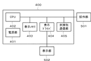
図3は、電子ペーパの制御部400の構成を示すブロック図である。
図3において、制御部400は、操作部501により操作された指示内容に従って制御を行う。
電源部401はバッテリーで構成され、CPU402、表示メモリ403、表示ドライバ404、非接触通信部405、操作部501、表示部502に電源供給を行う。
FIG. 3 is a block diagram illustrating a configuration of the electronic
In FIG. 3, the
The
CPU402は操作部501による操作コマンドを受け取り、電子ペーパ全体を制御する。CPU402は、必要に応じて表示メモリ403に蓄積された画像データを、表示ドライバ404を経由して表示部502に画像データを必要に応じて送り出す。
表示部502は一般の電子ペーパで採用されている電極及び、表示粒子等で構成されていれば良い。非接触通信部405は、公知の無線通信技術や光通信技術を用いて、外部機器と電子ペーパへのデータの転送やドキュメントIDなどの各種情報の受け渡しに用いる。
The
The
図4は、電子ペーパを図1に示したスキャナ301の原稿台に置いた状態を示す平面図である。なお、本実施形態では、図1に示したMFPのスキャナ301の原稿が載置される位置の近傍には電子ペーパESの非接触通信部405と通信可能な非接触通信手段51A、51Bが備えられている。そして、非接触通信手段51A、51Bは非接触通信部405を介して、電子ペーパとの間で表示データや表示データを特定するためのドキュメントIDのやり取りが可能である。
FIG. 4 is a plan view showing a state in which the electronic paper is placed on the document table of the
例えば、電子ペーパESは、非接触通信部405を介して、電子ペーパESに表示された画像に対応するドキュメントIDをMFP1000に送信することができる。
For example, the electronic paper ES can transmit a document ID corresponding to the image displayed on the electronic paper ES to the
また、MFP1000から電子ペーパに情報を送信することも可能である。例えば、MFP1000のデータ格納部106に格納されているMFP内の画像データはMFPの画像処理部108により電子ペーパに転送可能な解像度に変換されて、電子ペーパに送信できる。その後、送信された画像データは、IO制御部104に接続されている前述の非接触通信手段51A、51Bを経由して、非接触通信部405によって電子ペーパにより受信される。また、画像データとともにMFP1000内で画像データとの対応付けを行うためのドキュメントIDが非接触通信部405へ送信される。
Information can also be transmitted from the
表示メモリ403には、MFP1000から受信した前述の画像データ及びそれに対応するドキュメントIDが蓄積される。
なお、画像データ及びそれに対応するドキュメントIDは、データ格納部106ではなく、ネットワーク200経由でMFP1000と接続された外部機器に蓄積されるように構成してもよい。
スキャナ301には、コピーを行う原稿のサイズを検知する原稿検知センサ52〜54が埋め込まれている。なお、原稿検知センサ52〜54は、原稿台に載置される原稿のサイズを検知する場合に用いられる。また、原稿検知センサ52〜54は、原稿台に載置される原稿の向きを検知する。なお、原稿検知センサ52〜54は、原稿台に電子ペーパESが載置された場合に、電子ペーパESのサイズ、載置される向きを検知する。
The
Note that the image data and the corresponding document ID may be stored in an external device connected to the
In the
図4に示すように、現在、原稿台上に埋め込まれている原稿検知センサのうち、左下の原稿検知センサ54のみが電子ペーパESを検知している状態である。このため、CPU101は、センサの配置の情報と、検知された値により電子ペーパESの原稿サイズがA4(A4縦)であると判定する。
また、図4の例は、電子ペーパのサイズがA4と自動判定され、図2の操作部107上で"2in1"に対応するボタンBT1をユーザが選択した状態を示している。
As shown in FIG. 4, only the lower left
The example of FIG. 4 shows a state in which the electronic paper size is automatically determined as A4, and the user has selected the button BT1 corresponding to “2 in 1” on the
次に、図4に示した状態で、ユーザがスタートボタンBT2を押すと、CPU101は、電子ペーパESに表示されている画像に対応する前述のドキュメントIDを非接触通信手段51A、51Bより受け取る。そして、CPU101は、ドキュメントIDに対応するデータ格納部106に格納されているMFP1000内の画像データを読み出す。
図2の操作部上で"2in1"が選択されている場合、読み出された画像データをA4の印刷用紙に2in1出力するために必要な解像度変換、画像回転を画像処理部108で行う。そして、画像処理後の画像データを印字に必要な画像フォーマットに変換した後、プリンタ302に印刷データを送り、プリンタ302はA4用紙を給紙して画像印字を行い、排紙を行う。
Next, when the user presses the start button BT2 in the state shown in FIG. 4, the
When “2 in 1” is selected on the operation unit in FIG. 2, the
図4に示すMFP1000では以上の流れに従って電子ペーパESの画像を印字した様子を示している。
図5は、電子ペーパESを図1に示したスキャナ301の原稿台に置いた状態を示す平面図である。A4サイズの電子ペーパESが横向きに原稿台に載置された状態を示している。また、電子ペーパESは図4の操作部501に表示されていた画像を拡大して三角形の位置にスクロールした状態であることを示している。従って、図4に示した電子ペーパESの破線で示した図形のうち、左上の三角形が拡大され、操作部107によりプレビューされた状態である。
In the
FIG. 5 is a plan view showing a state where the electronic paper ES is placed on the document table of the
図5において、原稿検知センサは図4に示した時と異なり、左下の原稿検知センサ54は用紙を検知せず、右上の原稿検知センサ52によってのみ電子ペーパESを検知する。このため、CPU101は電子ペーパESのサイズをA4R(A4横)と判定する。
In FIG. 5, the document detection sensor differs from that shown in FIG. 4 in that the lower left
また、本例では、ユーザが操作する図2に示した操作部107上で倍率が選択され、"A4R → A3"の拡大モードが選択されている。
このような状態で、ユーザが図5の状態でスタートボタンBT2を押すと、電子ペーパESに表示されている画像に対応する前述のドキュメントIDを非接触通信手段51A、51Bで読み取る。そして、CPU101は、読み取られたドキュメントIDに対応するデータ格納部106に格納されているMFP1000内の画像データをRAM102上に読み出す。
In this example, the magnification is selected on the
In this state, when the user presses the start button BT2 in the state shown in FIG. 5, the above-described document ID corresponding to the image displayed on the electronic paper ES is read by the non-contact communication means 51A and 51B. Then,
また、図2に示す操作部107上で"表示部分選択"に対応するボタンBT3が選択されているため(この場合、三角形の部分)、電子ペーパESに表示されている選択されたイメージをスキャナ301が読み取る。
この際、電子ペーパES上で画像が拡大、スクロールされていることを、画像処理部108がスキャナ301でスキャンされた画像の特徴により自動検出する。このため、CPU101は、検出された画像の特徴に合わせた部分のみ画像データをデータ格納部106から読み出して、RAM102に保持する。例えば、CPU101は、ドキュメントIDに対応する画像をHDD106から読出し、読み出された画像に含まれる画像のうち、スキャンされた画像の特徴に類似する特徴を持つ画像をRAM102に保持させる。
In addition, since the button BT3 corresponding to “display portion selection” is selected on the
At this time, the
そして、読み出された画像データはA4Rの向きのまま、A3用紙に拡大出力可能な解像度に画像処理部108で変換を行った後、プリンタ302に印刷データを送る。プリンタ302は、A3用紙を給紙して画像印字を行い、排紙を行う。図5は以上の流れに従って、画像データを印刷した様子を示している。
Then, the read image data is converted by the
図6は、本実施形態を示す画像処理装置におけるデータ処理手順の一例を示すフローチャートである。本例は、図1に示したスキャナ301で読み取られた画像データの特徴を抽出する処理例である、なお、S601〜S605は各ステップを示す。また、各ステップは、CPU101がROM103に記憶された制御プログラムをRAM102にロードして実行する。
まず、CPU101は、S601で画像処理部108にRAM102に保持される画像データのエッジ抽出を実行させる。なお、抽出の方法は一般に用いられているエッジ抽出フィルタ等の手段を用いれば良い。
FIG. 6 is a flowchart illustrating an example of a data processing procedure in the image processing apparatus according to the present embodiment. This example is an example of processing for extracting features of image data read by the
First, in step S <b> 601, the
次に、S602において、画像処理部108に、抽出されたエッジ部を生成する画素の近傍探索を行い、つながりのある画素の追跡を実行させる。そして、S603で、画像処理部108に、画素の追跡を行うとともに、つながりのあると見なされた画素群に対してはラベリング(画素群に対するラベル付け)を行う。
次に、S604で、画像処理部108は、ラベリングされた後はそれぞれの画素群の存在する座標情報抽出を行う。そして、S605で、画像処理部108は、画素群の存在範囲を特徴情報として保存して、本処理を終了する。
In step S <b> 602, the
In step S604, the
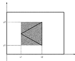
図7は、図1に示した画像処理部108による画像処理状態を説明する図である。本例は、画像データの画素群の存在範囲が(x1,y1)〜(x2,y2)であることを示している。これにより、対象の画像の大きさやオフセット(スクロールの状況)を把握することができる。
FIG. 7 is a diagram illustrating an image processing state by the
図8は、図1に示した画像処理部108による画像処理状態を説明する図である。
この特徴情報抽出処理は、同一サイズの画像に対して、画像の識別を行う目的で実行される。具体的には、画像のヒストグラム情報を抽出する方法で、図8の様に画像の特定のサンプリングライン上に存在する画素の濃度平均値をヒストグラムデータとして保存する。これによって、画像の濃度分布の特徴から画像を特定することができる。
図9は、図1に示した画像処理部108による画像処理で抽出された座標とラベルとの関係を説明する図である。本例は、図6に示した特徴情報抽出処理によって抽出してデータベースとして保持した例を示す。データ格納部106に保持されるデータベースは、ラベリングされた画素群毎に画像の存在範囲(座標)、サンプリングライン毎の濃度ヒストグラムデータで構成されている。図10に示すx1、y1、x2、y2が画像の存在範囲(座標)を示し、d1〜dNが、濃度イストグラムデータを示している。
FIG. 8 is a diagram illustrating an image processing state by the
This feature information extraction process is executed for the purpose of image identification for images of the same size. Specifically, by the method of extracting the histogram information of the image, the average density value of the pixels existing on a specific sampling line of the image is stored as histogram data as shown in FIG. Thereby, the image can be specified from the feature of the density distribution of the image.
FIG. 9 is a diagram for explaining the relationship between the coordinates extracted by the image processing by the
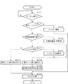
図10は、本実施形態を示す画像処理装置(MFP100)がスキャナに載置された原稿を読み取る場合の処理手順を示すフローチャートである。なお、S701〜S711の各ステップは、コンピュータのCPU101がROM103に記憶された制御プログラムをRAM102にロードして実行する。
FIG. 10 is a flowchart illustrating a processing procedure when the image processing apparatus (MFP 100) according to the present exemplary embodiment reads a document placed on a scanner. Note that the steps of S701 to S711 are executed by the
まず、S701で、図2の操作部において、ユーザがスタートボタンBT2を押下されたかどうかをCPU101が判断する。ここで、スタートボタンBT2を押下されたとCPU101が判断した場合は、S702で、電子ペーパキーBT4が押されて電子ペーパモードが選択された状態かどうかCPU101が判断する。
ここで、電子ペーパモードが選択されていないとCPU101が判断した場合は、S703へ進み、通常のコピーと同様、電子ペーパESの画面をそのままスキャンする。そして、S710で、プリンタ302へ読み取った画像データを出力することでハードコピーを行い、本処理を終了する。
First, in S701, the
If the
一方、S702で、電子ペーパモードが選択されたとCPU101が判断した場合は、S704へ進む。そして、S704で、電子ペーパESが表示されている画像に対応する前述のドキュメントIDを取得するため、前述の非接触通信が可能かどうかをCPU101が判断する。ここで、非接触通信が可能であるとCPU101が判断した場合は、S705へ進む。
そして、S705で、CPU101は、非接触通信により電子ペーパESからドキュメントIDを取得する。そして、CPU101は、取得したドキュメントIDに基づいて、電子ペーパESが表示されている画像に対応するデータ格納部106に保存されている複数のドキュメントの中から前述のドキュメントを特定する。
On the other hand, if the
In step S <b> 705, the
一方、S704で、非接触通信が可能でないとCPU101が判断した場合は、S706へ進む。そして、S706で、電子ペーパESの画像内にドキュメントIDを示すバーコードが検出可能か否かをCPU101が判断する。このバーコードは、HDD106に格納されたドキュメントを特定するドキュメントIDを示すものであり、あらかじめ電子ペーパに画像データを送信する際に、画像に付加しておけばよい。
ここで、バーコードが検出可能であるとCPU101が判断した場合は、S707で、バーコードにより示されるドキュメントIDを取得する。そして、CPU101は、取得したドキュメントIDに基づいて、電子ペーパESに表示されている画像に対応するドキュメントを特定する。
On the other hand, if the
If the
一方、S706で、バーコードを検出可能でないとCPU101が判断した場合は、S711で、電子ペーパESの表示部502をスキャナ301でスキャンする。そして、S710で、CPU101はスキャナ301で読み取られた画像をプリンタ302で印刷し、本処理を終了する。
On the other hand, if the
S705、S707でドキュメントIDを取得した場合、S708で、電子ペーパESの表示部502をスキャナ301でスキャンする。そして、S709で、特定されたドキュメントIDと図9に示したデータを元に座標情報から、濃度分布比較を行って電子ペーパが表示されている画像の領域、表示されている画像の拡大率などを特定する。
なお、画像の拡大率は、図9に示す例えばLabel nの座標データより、(Yn−Yn+1)/(Xn−Xn+1)でCPU101が算出する比率の近似度により類似ラベルを探す。そして、CPU101は、類似ラベルとのXi−Xi+1の長さの比率で拡大率を解析する。
次に、CPU101は、想定された画像の拡大率に応じてサンプリングライン数を互いに揃え、その状態でヒストグラム値を比較して、比較している画像データが互いに対応しているものかどうかを判別する。
When the document ID is acquired in S705 and S707, the
For the image enlargement ratio, for example, a similar label is searched based on the degree of approximation of the ratio calculated by the
Next, the
また、図9に示す座標情報は、前述の通り、電子ペーパES上での画像の拡大率、オフセット(スクロールの状況)を判断するためにも用いることができる。
そして、S710で、CPU101は、特定されたドキュメントを、S709で特定された拡大率で画像処理された印刷データをプリンタ302へ出力して印刷し、本処理を終了する。これによって、電子ペーパESに表示されている状態と同じ状態の画像を高画質で印刷できる。
Further, as described above, the coordinate information shown in FIG. 9 can also be used to determine the enlargement ratio and offset (scrolling status) of the image on the electronic paper ES.
In step S <b> 710, the
以上の説明の通り、電子ペーパに表示されている内容を通常のコピーを取る時と同じ操作を行うことによって、簡単に所望の状態のコピーを行うことができる。なお、ユーザによって"A4R → A3"のように拡大率が別途指定されている場合、S709で解析された拡大率に加えて、ユーザによって指定された拡大率によって画像を拡大して印刷すればよい。電子ペーパESに表示されている状態と同じ状態の画像をA3の用紙に印刷する際に、ユーザによって指定された拡大率に従って拡大して印刷することができる。 As described above, the desired state can be easily copied by performing the same operation as the normal copy of the contents displayed on the electronic paper. When the enlargement ratio is separately designated as “A4R → A3” by the user, the image may be enlarged and printed according to the enlargement ratio designated by the user in addition to the enlargement ratio analyzed in S709. . When an image in the same state as that displayed on the electronic paper ES is printed on the A3 paper, the image can be enlarged and printed according to the enlargement factor designated by the user.
なお、上記実施形態では、電子ペーパESが表示データを1ページ分表示する場合について説明したが、表示データを複数ページ分表示したものを保存し、保存した表示データに基づいて、まとめて印刷するようにしてもよい。このとき、CPU101は、図10に示すS704〜S710の処理を複数ページ分繰り返すことで画像処理装置が実行する画像処理モードに対応した画像処理を行える。つまり、複数のページを1枚の用紙に出力するプリントする処理や、複数のページを両面プリントする処理、これらの組み合わせ等に対応することができる。
In the above embodiment, the case where the electronic paper ES displays the display data for one page has been described. However, the display data displayed for a plurality of pages is stored, and is printed collectively based on the stored display data. You may do it. At this time, the
また、電子ペーパが複数のページの画像データを保持しており、それら複数ページ分の画像データを印刷したい場合、MFP1000は、それら複数ページを示すドキュメントIDに基づいて画像データを印刷してもよい。その場合、ユーザは、不図示の複数ページモードを指示するボタンを押した状態で、電子ペーパESを原稿台にセットし、スタートキーを押す。その後、MFP1000のCPU101は、複数ページ分のドキュメントIDを電子ペーパESから取得する。その後、CPU101は、電子ペーパESのCPU402と通信を行い、電子ペーパに表示されているページを1ページずつ切替えながら表示されたデータを読取り、S704〜S710の処理をする。それによって、複数のページからなるドキュメントを印刷する際に、ユーザは、1ページずつ電子ペーパの表示を切替える操作をせずとも、表示されているドキュメントに対応する複数のページを容易に印刷することができる。
Further, when the electronic paper holds image data of a plurality of pages and wants to print the image data for the plurality of pages, the
また、ここでは電子ペーパに表示されている画像データが、画像処理装置に蓄積されている例について説明したがこれに限らない。電子ペーパから表示されている画像の元のデータを外部のPCなどから取得し、スキャナで読み取った画像と同様の比較をすることによって印刷するようにしてもよい。これによって、元のデータから電子ペーパに表示されている画像と同じ状態の高画質の印刷用画像データを作成することができる。
また、保存先が情報処理装置や他の画像処理装置である場合に、設定された画像処理モードに対応した処理を依頼し、当該画像処理モードに対応した画像処理がなされた印刷データを取得するように構成してもよい。これにより、プリンタ302が画像処理して印刷を完了するまでに要する処理時間を短縮することも可能である。
本発明の各工程は、ネットワーク又は各種記憶媒体を介して取得したソフトウエア(プログラム)をCPUなどの処理装置にて実行することでも実現できる。
本発明は上記実施形態に限定されるものではなく、本発明の趣旨に基づき種々の変形(各実施形態の有機的な組合せを含む)が可能であり、それらを本発明の範囲から除外するものではない。
本発明の様々な例と実施形態を示して説明したが、当業者であれば、本発明の趣旨と範囲は、本明細書内の特定の説明に限定されるのではない。
Although an example in which the image data displayed on the electronic paper is stored in the image processing apparatus has been described here, the present invention is not limited to this. The original data of the image displayed from the electronic paper may be acquired from an external PC or the like and printed by performing the same comparison as the image read by the scanner. Thereby, it is possible to create high-quality print image data in the same state as the image displayed on the electronic paper from the original data.
Further, when the storage destination is an information processing apparatus or another image processing apparatus, a request for processing corresponding to the set image processing mode is requested, and print data subjected to image processing corresponding to the image processing mode is acquired. You may comprise as follows. Accordingly, it is possible to shorten the processing time required for the
Each process of the present invention can also be realized by executing software (program) acquired via a network or various storage media by a processing device such as a CPU.
The present invention is not limited to the above embodiment, and various modifications (including organic combinations of the embodiments) are possible based on the spirit of the present invention, and these are excluded from the scope of the present invention. is not.
While various examples and embodiments of the present invention have been shown and described, the spirit and scope of the present invention are not limited to the specific descriptions in the present specification by those skilled in the art.
100 メインコントローラ
101 CPU
102 RAM
103 ROM
100
102 RAM
103 ROM
Claims (11)
前記取得手段が取得した情報に基づいて、前記画像に対応する画像データを当該画像データが保存された記憶手段から読み出す読出手段と、
前記原稿台に載置される情報表示媒体のサイズを検知する検知手段と、
前記読出手段によって読み出された画像データを、前記検知手段によって検知された前記情報表示媒体のサイズに基づいて印刷する印刷手段とを備えることを特徴とする画像処理装置。 An acquisition means for acquiring information for specifying an image displayed on the information display medium placed on the document table;
Reading means for reading out image data corresponding to the image from the storage means in which the image data is stored, based on the information acquired by the acquisition means;
Detecting means for detecting the size of the information display medium placed on the document table;
An image processing apparatus comprising: a printing unit that prints image data read by the reading unit based on the size of the information display medium detected by the detection unit.
前記印刷手段は、前記読出手段によって読み出された画像データを、前記検知手段によって検知された前記情報表示媒体のサイズ及び向きに基づいて印刷することを特徴とする請求項1に記載の画像処理装置。 The detecting means detects the size and orientation of the information display medium placed on the document table;
The image processing according to claim 1, wherein the printing unit prints the image data read by the reading unit based on the size and orientation of the information display medium detected by the detection unit. apparatus.
前記読取手段によって読み取られた画像の拡大率を解析する解析手段とをさらに備え、
前記印刷手段は、前記解析手段により解析された拡大率に基づいて、前記読出手段によって読み出された画像データを印刷することを特徴とする請求項1または2に記載の画像処理装置。 Reading means for reading an image displayed on the information display medium placed on the document table;
Analyzing means for analyzing the magnification of the image read by the reading means,
The image processing apparatus according to claim 1, wherein the printing unit prints image data read by the reading unit based on an enlargement ratio analyzed by the analyzing unit.
原稿台に載置される情報表示媒体に表示された画像を特定するための情報を取得する取得ステップと、
前記取得ステップが取得した情報に基づいて、前記画像に対応する画像データを当該画像データが保存された記憶手段から読み出す読出ステップと、
前記原稿台に載置される情報表示媒体のサイズを検知する検知ステップと、
前記読出ステップによって読み出された画像データを、前記検知ステップによって検知された前記情報表示媒体のサイズに基づいて印刷する印刷ステップとを備えることを特徴とする画像処理方法。 An image processing method of an image processing apparatus,
An acquisition step of acquiring information for specifying an image displayed on the information display medium placed on the document table;
A reading step of reading out image data corresponding to the image from the storage means in which the image data is stored based on the information acquired in the acquisition step;
A detection step of detecting the size of the information display medium placed on the document table;
An image processing method comprising: a printing step of printing the image data read by the reading step based on the size of the information display medium detected by the detection step.
前記印刷ステップは、前記読出ステップによって読み出された画像データを、前記検知ステップによって検知された前記情報表示媒体のサイズ及び向きに基づいて印刷することを特徴とする請求項6に記載の画像処理方法。 The detecting step detects the size and orientation of the information display medium placed on the document table,
The image processing according to claim 6, wherein the printing step prints the image data read by the reading step based on the size and orientation of the information display medium detected by the detection step. Method.
前記読取ステップによって読み取られた画像の拡大率を解析する解析ステップとをさらに備え、
前記印刷ステップは、前記解析ステップにより解析された拡大率に基づいて、前記読出ステップによって読み出された画像データを印刷することを特徴とする請求項6または7に記載の画像処理方法。 A reading step of reading an image displayed on the information display medium placed on the document table;
An analysis step of analyzing an enlargement ratio of the image read by the reading step,
The image processing method according to claim 6 or 7, wherein the printing step prints the image data read by the reading step based on the enlargement ratio analyzed by the analyzing step.
Priority Applications (1)
| Application Number | Priority Date | Filing Date | Title |
|---|---|---|---|
| JP2009053286A JP2010212743A (en) | 2009-03-06 | 2009-03-06 | Image processing apparatus, image processing method and program |
Applications Claiming Priority (1)
| Application Number | Priority Date | Filing Date | Title |
|---|---|---|---|
| JP2009053286A JP2010212743A (en) | 2009-03-06 | 2009-03-06 | Image processing apparatus, image processing method and program |
Publications (2)
| Publication Number | Publication Date |
|---|---|
| JP2010212743A true JP2010212743A (en) | 2010-09-24 |
| JP2010212743A5 JP2010212743A5 (en) | 2012-04-19 |
Family
ID=42972525
Family Applications (1)
| Application Number | Title | Priority Date | Filing Date |
|---|---|---|---|
| JP2009053286A Pending JP2010212743A (en) | 2009-03-06 | 2009-03-06 | Image processing apparatus, image processing method and program |
Country Status (1)
| Country | Link |
|---|---|
| JP (1) | JP2010212743A (en) |
Cited By (3)
| Publication number | Priority date | Publication date | Assignee | Title |
|---|---|---|---|---|
| CN103179306A (en) * | 2011-12-20 | 2013-06-26 | 柯尼卡美能达商用科技株式会社 | Image forming apparatus and control method of same |
| WO2018232733A1 (en) * | 2017-06-23 | 2018-12-27 | Thomson Licensing | Method and device for providing a printing service |
| JP2020145632A (en) * | 2019-03-08 | 2020-09-10 | 富士ゼロックス株式会社 | Image processing apparatus, image processing system, and program |
Citations (2)
| Publication number | Priority date | Publication date | Assignee | Title |
|---|---|---|---|---|
| JP2005197834A (en) * | 2003-12-26 | 2005-07-21 | Konica Minolta Business Technologies Inc | Image forming apparatus, image forming method, image forming program, and computer readable recording medium recorded with the program |
| JP2009004980A (en) * | 2007-06-20 | 2009-01-08 | Ricoh Co Ltd | Image reader, image forming apparatus, electronic paper and program |
-
2009
- 2009-03-06 JP JP2009053286A patent/JP2010212743A/en active Pending
Patent Citations (2)
| Publication number | Priority date | Publication date | Assignee | Title |
|---|---|---|---|---|
| JP2005197834A (en) * | 2003-12-26 | 2005-07-21 | Konica Minolta Business Technologies Inc | Image forming apparatus, image forming method, image forming program, and computer readable recording medium recorded with the program |
| JP2009004980A (en) * | 2007-06-20 | 2009-01-08 | Ricoh Co Ltd | Image reader, image forming apparatus, electronic paper and program |
Cited By (6)
| Publication number | Priority date | Publication date | Assignee | Title |
|---|---|---|---|---|
| CN103179306A (en) * | 2011-12-20 | 2013-06-26 | 柯尼卡美能达商用科技株式会社 | Image forming apparatus and control method of same |
| JP2013131828A (en) * | 2011-12-20 | 2013-07-04 | Konica Minolta Business Technologies Inc | Image forming apparatus, and image forming apparatus control program |
| US8896882B2 (en) | 2011-12-20 | 2014-11-25 | Konica Minolta Business Technologies, Inc. | Image forming apparatus and computer readable recording medium storing control program for printing displayed image from portable display terminal |
| CN103179306B (en) * | 2011-12-20 | 2015-08-26 | 柯尼卡美能达商用科技株式会社 | The control method of image processing system and image processing system |
| WO2018232733A1 (en) * | 2017-06-23 | 2018-12-27 | Thomson Licensing | Method and device for providing a printing service |
| JP2020145632A (en) * | 2019-03-08 | 2020-09-10 | 富士ゼロックス株式会社 | Image processing apparatus, image processing system, and program |
Similar Documents
| Publication | Publication Date | Title |
|---|---|---|
| US7414748B2 (en) | Image input/output apparatus, method of controlling image input/output apparatus, image input/output system, and storage media | |
| JP6849387B2 (en) | Image processing device, image processing system, control method of image processing device, and program | |
| US10546219B2 (en) | Printing system, printing apparatus, printing control apparatus, and control method of printing system | |
| US20130182285A1 (en) | Image forming apparatus and document preview method for the same | |
| US20090303508A1 (en) | Image reading apparatus and image forming apparatus | |
| JP4635907B2 (en) | Printing device | |
| JP2015049719A (en) | Print control device, print control method, program, and recording medium | |
| KR20090020980A (en) | Terminal unit, image forming apparatus, printing system comprising them and printing methods of thereof | |
| JP2010212743A (en) | Image processing apparatus, image processing method and program | |
| JP2008242564A (en) | Printer driver, program, and recording medium | |
| JP6525708B2 (en) | Image reading apparatus and control method of image reading apparatus | |
| JP2015052831A (en) | Print control unit, print control method, program, and record medium | |
| JP2014116737A (en) | Image formation device, image formation device control method, and program | |
| JP4412211B2 (en) | Skew correction method, program, image processing apparatus, and image processing system | |
| CN101582968B (en) | Information displaying and printing system | |
| JP5268617B2 (en) | Image forming apparatus, image forming apparatus control method, and computer program | |
| JP2019220906A (en) | Image processing system, print instruction device, image processing device, and program | |
| JP2009220476A (en) | Printer | |
| JP2008263275A (en) | Image read system, and control method of image read system | |
| US20150062646A1 (en) | Sheet management apparatus, control method of sheet management apparatus, and storage medium | |
| JP2006270217A (en) | Apparatus, method, and program for controlling copying, and copying system | |
| KR100571793B1 (en) | host capable selecting coyp function and a method thereof | |
| US20130063775A1 (en) | Image forming apparatus capable of providing actual-size preview, method of controlling the same, and storage medium | |
| US8384943B2 (en) | Image processing apparatus, control method of image processing apparatus, and storage medium for managing images in a multi-image file | |
| JP2007293736A (en) | Printing system and printer therefor |
Legal Events
| Date | Code | Title | Description |
|---|---|---|---|
| A521 | Written amendment |
Free format text: JAPANESE INTERMEDIATE CODE: A523 Effective date: 20120305 |
|
| A621 | Written request for application examination |
Free format text: JAPANESE INTERMEDIATE CODE: A621 Effective date: 20120305 |
|
| A977 | Report on retrieval |
Free format text: JAPANESE INTERMEDIATE CODE: A971007 Effective date: 20130205 |
|
| A131 | Notification of reasons for refusal |
Free format text: JAPANESE INTERMEDIATE CODE: A131 Effective date: 20130212 |
|
| A521 | Written amendment |
Free format text: JAPANESE INTERMEDIATE CODE: A523 Effective date: 20130412 |
|
| A02 | Decision of refusal |
Free format text: JAPANESE INTERMEDIATE CODE: A02 Effective date: 20130820 |