JP2010205346A - Optical unit and optical information recording/reproducing device - Google Patents
Optical unit and optical information recording/reproducing device Download PDFInfo
- Publication number
- JP2010205346A JP2010205346A JP2009050460A JP2009050460A JP2010205346A JP 2010205346 A JP2010205346 A JP 2010205346A JP 2009050460 A JP2009050460 A JP 2009050460A JP 2009050460 A JP2009050460 A JP 2009050460A JP 2010205346 A JP2010205346 A JP 2010205346A
- Authority
- JP
- Japan
- Prior art keywords
- optical path
- optical
- unit
- beams
- light
- Prior art date
- Legal status (The legal status is an assumption and is not a legal conclusion. Google has not performed a legal analysis and makes no representation as to the accuracy of the status listed.)
- Withdrawn
Links
- 230000003287 optical effect Effects 0.000 title claims abstract description 628
- 239000004973 liquid crystal related substance Substances 0.000 claims description 57
- 238000001514 detection method Methods 0.000 claims description 13
- 230000005540 biological transmission Effects 0.000 claims 1
- 230000010287 polarization Effects 0.000 description 23
- 239000004988 Nematic liquid crystal Substances 0.000 description 20
- 229920000642 polymer Polymers 0.000 description 17
- 238000000034 method Methods 0.000 description 12
- 239000011159 matrix material Substances 0.000 description 9
- 230000006870 function Effects 0.000 description 8
- 239000000758 substrate Substances 0.000 description 5
- 230000007274 generation of a signal involved in cell-cell signaling Effects 0.000 description 4
- 230000007246 mechanism Effects 0.000 description 4
- 230000008569 process Effects 0.000 description 4
- 238000002834 transmittance Methods 0.000 description 4
- 230000035945 sensitivity Effects 0.000 description 3
- 230000002159 abnormal effect Effects 0.000 description 2
- 230000003321 amplification Effects 0.000 description 2
- 238000004519 manufacturing process Methods 0.000 description 2
- 239000000463 material Substances 0.000 description 2
- 238000003199 nucleic acid amplification method Methods 0.000 description 2
- 230000035699 permeability Effects 0.000 description 2
- 238000010521 absorption reaction Methods 0.000 description 1
- 239000012782 phase change material Substances 0.000 description 1
- 230000009467 reduction Effects 0.000 description 1
Images


Landscapes
- Optical Head (AREA)
Abstract
Description
本発明は、光記録媒体に対して情報の記録再生を行うための光学ユニットおよび光学的情報記録再生装置に関するものである。 The present invention relates to an optical unit and an optical information recording / reproducing apparatus for recording / reproducing information on / from an optical recording medium.
情報の記録再生に用いられる光記録媒体として、ディスク状の光記録媒体とカード状の光記録媒体とが知られている。ディスク状の光記録媒体に対して光学ユニットにより情報の記録再生を行う場合、光学ユニットを光記録媒体の半径方向へ移動させると共に光記録媒体を回転させる。このため、光記録媒体の中心部に光記録媒体をクランプするためのクランプ領域を設ける必要があり、光記録媒体の中心部をデータ領域として用いることができない。これに対し、カード状の光記録媒体に対して光学ユニットにより情報の記録再生を行う場合、光学ユニットまたは光記録媒体を光記録媒体の面内の2方向へ移動させる。このため、光記録媒体にクランプ領域を設ける必要がなく、光記録媒体の全面をデータ領域として用いることができる。 As an optical recording medium used for recording / reproducing information, a disk-shaped optical recording medium and a card-shaped optical recording medium are known. When recording and reproducing information with respect to a disk-shaped optical recording medium by an optical unit, the optical unit is moved in the radial direction of the optical recording medium and the optical recording medium is rotated. For this reason, it is necessary to provide a clamp area for clamping the optical recording medium at the center of the optical recording medium, and the center of the optical recording medium cannot be used as the data area. On the other hand, when recording / reproducing information with respect to a card-like optical recording medium by an optical unit, the optical unit or the optical recording medium is moved in two directions within the surface of the optical recording medium. Therefore, it is not necessary to provide a clamp area on the optical recording medium, and the entire surface of the optical recording medium can be used as the data area.
光学ユニットに単一の対物レンズを設け、カード状の光記録媒体の全面に対して単一の対物レンズを用いて情報の記録再生を行う場合、対物レンズにより光記録媒体内に形成される集光スポットが、光記録媒体のデータ領域の全部を走査する必要がある。このため、対物レンズまたは光記録媒体を、光記録媒体の面内の2方向へ光記録媒体の面積と同じ範囲内で移動させる必要がある。従って、対物レンズまたは光記録媒体を移動させるための機構が大型化してしまう。 When a single objective lens is provided in the optical unit and information is recorded / reproduced on the entire surface of the card-like optical recording medium using the single objective lens, the optical lens formed in the optical recording medium by the objective lens is used. The light spot needs to scan the entire data area of the optical recording medium. For this reason, it is necessary to move the objective lens or the optical recording medium in two directions in the plane of the optical recording medium within the same range as the area of the optical recording medium. Therefore, the mechanism for moving the objective lens or the optical recording medium is increased in size.
これに対し、光学ユニットに複数の対物レンズを設け、カード状の光記録媒体の全面に対して複数の対物レンズを選択的に用いて情報の記録再生を行う場合、各々の対物レンズにより光記録媒体内に形成される集光スポットが、光記録媒体のデータ領域の一部を走査すれば良い。このため、各々の対物レンズまたは光記録媒体を、光記録媒体の面内の2方向へ光記録媒体の面積より狭い範囲内で移動させれば良い。従って、各々の対物レンズまたは光記録媒体を移動させるための機構を小型化することができる。例えば、特許文献1には、レーザー光源から出力されるレーザー光の光路を切り替える手段と、光記録媒体のトラックに垂直な方向にずらした2つの対物レンズとを有する光ピックアップが開示されている。
On the other hand, when a plurality of objective lenses are provided in the optical unit and information is recorded and reproduced by selectively using the plurality of objective lenses on the entire surface of the card-like optical recording medium, optical recording is performed by each objective lens. The focused spot formed in the medium may scan a part of the data area of the optical recording medium. Therefore, each objective lens or optical recording medium may be moved in two directions in the plane of the optical recording medium within a range narrower than the area of the optical recording medium. Therefore, a mechanism for moving each objective lens or optical recording medium can be reduced in size. For example,
また、光記録媒体に対する情報の記録再生の速度を向上させる技術として、光学ユニットに複数のビームを生成する光源部と複数のビームを受光する光検出部とを設け、複数のビームを用いて光記録媒体に対して並列に情報の記録再生を行う技術が知られている。例えば、特許文献2には、複数の光ビームを用いて複数のトラックから同時に情報を再生す方法が開示されている。
In addition, as a technique for improving the speed of recording / reproducing information with respect to an optical recording medium, an optical unit is provided with a light source unit that generates a plurality of beams and a light detection unit that receives the plurality of beams. A technique for recording and reproducing information in parallel with a recording medium is known. For example,
特許文献1のように複数の対物レンズを用いレーザー光の光路を切り替えることで機構の小型化を図り、且つ特許文献2のように1つの対物レンズ当たり複数の光ビームを用いて並列に情報の記録再生を行おうとすれば、光路切り替えに伴って使用対物レンズの光学的配置が異なることで、複数の光ビーム同士の間で対物レンズ開口数が異なるようになる。かくして、幾つかの光ビームについては、対物レンズ開口数が小さくなって、対物レンズにより光記録媒体内に形成される集光スポットの径が大きくなり、記録時の感度の低下および再生時の分解能の低下が生じる。このため、光記録媒体に対する情報記録再生の品質が低下する。
The mechanism can be reduced in size by switching the optical path of the laser beam using a plurality of objective lenses as in
本発明の目的は、光記録媒体に対し、複数の対物レンズを選択的に用いると共に、複数の光ビームを用いて並列に情報の記録再生を行う光学ユニットにおける上に述べた課題を解決し、複数の光ビームに対する対物レンズ開口数の均一化を図り、光記録媒体に対する情報記録再生の品質を向上させることができる光学ユニットおよび光学的情報記録再生装置を提供することにある。 An object of the present invention is to solve the above-described problems in an optical unit that selectively uses a plurality of objective lenses for an optical recording medium and records and reproduces information in parallel using a plurality of light beams, An object of the present invention is to provide an optical unit and an optical information recording / reproducing apparatus that can improve the quality of information recording / reproducing with respect to an optical recording medium by making the numerical apertures of objective lenses uniform for a plurality of light beams.
尚、本明細書においては、光ビームのことを単に「ビーム」ということがある。 In the present specification, the light beam may be simply referred to as “beam”.
本発明によれば、上記目的を達成すべく、
複数のビームを用い、光記録媒体に対して並列に記録再生を行う光学ユニットであって、
前記光学ユニットは、複数のビームを生成する光源部と、複数のビームを受光する光検出部と、複数の対物レンズと、前記光源部から前記複数の対物レンズまでの複数の往路光路および前記複数の対物レンズから前記光検出部までの複数の復路光路のそれぞれを切り替える光路切替部と、前記往路光路の光路長および前記復路光路の光路長のそれぞれを補正する光路長補正部とを有しており、
前記光路切替部は、前記光源部で生成された複数のビームが前記複数の対物レンズのうちの選択された対物レンズを介して前記光記録媒体へ導かれ、該光記録媒体で反射された複数のビームが前記選択された対物レンズを介して前記光検出部へ導かれるように、前記往路光路および前記復路光路を切り替え、
前記光路長補正部は、前記往路光路の光路長および前記復路光路の光路長のそれぞれを前記複数の対物レンズの全てに対して実質的に一定にするように、前記選択された対物レンズに対応して前記往路光路の光路長および前記復路光路の光路長を補正することを特徴とする光学ユニット、
が提供される。
According to the present invention, in order to achieve the above object,
An optical unit that uses a plurality of beams to perform recording and reproduction in parallel with an optical recording medium,
The optical unit includes: a light source unit that generates a plurality of beams; a light detection unit that receives a plurality of beams; a plurality of objective lenses; a plurality of forward optical paths from the light source unit to the plurality of objective lenses; An optical path switching unit that switches each of a plurality of return path optical paths from the objective lens to the light detection unit, and an optical path length correction unit that corrects each of the optical path length of the forward path optical path and the optical path length of the return path optical path. And
The optical path switching unit is configured to guide a plurality of beams generated by the light source unit to the optical recording medium through a selected objective lens among the plurality of objective lenses, and to reflect the plurality of beams reflected by the optical recording medium. Switching the forward optical path and the return optical path so that the beam is guided to the light detection unit through the selected objective lens,
The optical path length correction unit corresponds to the selected objective lens so that each of the optical path length of the forward path optical path and the optical path length of the return path optical path is substantially constant with respect to all of the plurality of objective lenses. And an optical unit for correcting the optical path length of the forward optical path and the optical path length of the backward optical path,
Is provided.
本発明においては、好ましくは、前記光源部で生成される複数のビームは発散光であり、前記光検出部で受光される複数のビームは収束光であり、前記光学ユニットは、前記光源部から前記選択された対物レンズへ向かう複数のビームを発散光から平行光へ変換し且つ前記選択された対物レンズから前記光検出部へ向かう複数のビームを平行光から収束光へ変換するコリメータレンズをさらに有する。本発明においては、好ましくは、前記光路長補正部は、前記コリメータレンズの後側焦点位置と前記選択された対物レンズの前側焦点位置とが一致するように、前記往路光路の光路長および前記復路光路の光路長を補正する。本発明においては、好ましくは、前記光学ユニットは、前記コリメータレンズの後側焦点位置であり且つ前記選択された対物レンズの前側焦点位置である位置に、開口をさらに有する。 In the present invention, preferably, the plurality of beams generated by the light source unit are divergent light, the plurality of beams received by the light detection unit are convergent light, and the optical unit is connected to the light source unit from the light source unit. A collimator lens that converts a plurality of beams directed to the selected objective lens from divergent light into parallel light and converts a plurality of beams directed from the selected objective lens to the light detection unit from parallel light into convergent light; Have. In the present invention, it is preferable that the optical path length correction unit includes the optical path length of the forward optical path and the return path so that the rear focal position of the collimator lens matches the front focal position of the selected objective lens. The optical path length of the optical path is corrected. In the present invention, it is preferable that the optical unit further includes an aperture at a position that is a rear focal position of the collimator lens and a front focal position of the selected objective lens.
本発明においては、好ましくは、前記光路長補正部は、前記往路光路の光路長を補正する往路用光路長補正部と前記復路光路の光路長を補正する復路用光路長補正部とを有する。本発明においては、好ましくは、前記光路長補正部は、入射光を透過させるか反射するかを切り替え可能な少なくとも一つの可変ミラーを有する。本発明においては、好ましくは、前記可変ミラーは液晶ブラッグミラーを含む。 In the present invention, it is preferable that the optical path length correction unit includes an outward path optical path length correction unit that corrects the optical path length of the forward path optical path and a return path optical path length correction unit that corrects the optical path length of the return path optical path. In the present invention, it is preferable that the optical path length correction unit includes at least one variable mirror that can switch whether incident light is transmitted or reflected. In the present invention, preferably, the variable mirror includes a liquid crystal Bragg mirror.
本発明においては、好ましくは、前記光路切替部は、入射光を透過させるか反射するかを切り替え可能な少なくとも一つの光路切替素子を有する。本発明においては、好ましくは、前記光路切替素子は液晶ブラッグミラーを含む。 In the present invention, it is preferable that the optical path switching unit includes at least one optical path switching element that can switch whether incident light is transmitted or reflected. In the present invention, preferably, the optical path switching element includes a liquid crystal Bragg mirror.
また、本発明によれば、上記目的を達成すべく、
上記の光学ユニットと、前記光路切替部を電気的に駆動する光路切替部駆動回路と、前記光路長補正部を電気的に駆動する光路長補正部駆動回路とを有することを特徴とする光学的情報記録再生装置、
が提供される。
Further, according to the present invention, in order to achieve the above object,
An optical unit comprising: the above optical unit; an optical path switching unit driving circuit that electrically drives the optical path switching unit; and an optical path length correction unit driving circuit that electrically drives the optical path length correction unit. Information recording / reproducing apparatus,
Is provided.
本発明においては、好ましくは、前記光学的情報記録再生装置は、前記光路切替部駆動回路および前記光路長補正部駆動回路を制御する制御回路をさらに有し、該制御回路は、前記複数の対物レンズについての選択を順次行い、この選択の度に、前記光路切替部駆動回路に前記選択された対物レンズに対応して前記往路光路および前記復路光路の切り替えのための信号を入力し、前記光路長補正部駆動回路に前記選択された対物レンズに対応して前記往路光路の光路長および前記復路光路の光路長の補正のための信号を入力する。 In the present invention, it is preferable that the optical information recording / reproducing apparatus further includes a control circuit that controls the optical path switching unit driving circuit and the optical path length correction unit driving circuit, and the control circuit includes the plurality of objectives. Each time the lens is selected, a signal for switching the forward optical path and the backward optical path corresponding to the selected objective lens is input to the optical path switching unit driving circuit. A signal for correcting the optical path length of the forward optical path and the optical path length of the backward optical path corresponding to the selected objective lens is input to the length correction unit driving circuit.
本発明の光学ユニットおよび光学的情報記録再生装置においては、複数の対物レンズのうちどの対物レンズを選択しても、光源部から選択された対物レンズまでの往路の光路長および選択された対物レンズから光検出部までの復路の光路長がそれぞれ実質的に一定になるように、光路長補正部により往路光路長および復路光路長が補正される。従って、複数の対物レンズのうちどの対物レンズが選択された場合も、選択された対物レンズの全てのビームに対する開口数が常に実質上一定である。対物レンズの開口数が常に実質上一定であると、対物レンズにより光記録媒体内に形成される集光スポットの径が常に実質上一定であり、記録時の感度の低下および再生時の分解能の低下が生じないため、光記録媒体に対して正しく情報の記録再生を行うことができる。 In the optical unit and the optical information recording / reproducing apparatus of the present invention, the optical path length of the forward path from the light source unit to the selected objective lens and the selected objective lens, regardless of which objective lens is selected from among the plurality of objective lenses The forward optical path length and the backward optical path length are corrected by the optical path length correction unit so that the optical path lengths from the optical path to the light detection unit are substantially constant. Therefore, no matter which objective lens is selected from among a plurality of objective lenses, the numerical aperture for all beams of the selected objective lens is always substantially constant. When the numerical aperture of the objective lens is always substantially constant, the diameter of the focused spot formed in the optical recording medium by the objective lens is always substantially constant, which reduces the sensitivity during recording and the resolution during reproduction. Since no reduction occurs, information can be recorded / reproduced correctly with respect to the optical recording medium.
以上のような本発明の光学ユニットおよび光学的情報記録再生装置によれば、光記録媒体に対し、複数の対物レンズを選択的に用いると共に、複数のビームを用いて並列に情報の記録再生を行う場合に、複数の光ビームに対する対物レンズ開口数が均一化されるので、光記録媒体に対する情報記録再生の品質を向上させることができる。 According to the optical unit and the optical information recording / reproducing apparatus of the present invention as described above, a plurality of objective lenses are selectively used for an optical recording medium, and information is recorded / reproduced in parallel using a plurality of beams. In this case, since the numerical aperture of the objective lens for a plurality of light beams is made uniform, the quality of information recording / reproducing with respect to the optical recording medium can be improved.
以下に、図面を参照して本発明の実施形態について説明する。 Embodiments of the present invention will be described below with reference to the drawings.
先ず、本発明実施形態の説明の便宜上、参考例の光学的情報記録再生装置につき説明する。カード状の光記録媒体に対し、複数の対物レンズを選択的に用いると共に、複数のビームを用いて並列に情報の記録再生を行う光学ユニットの参考例を図10に示す。図10の(a)、(b)はそれぞれ上面図、側面図である。光記録媒体33はカード状である。光学ユニットは、複数のビームを生成するレーザアレイ34と、複数のビームを受光する光検出器アレイ35と、選択的に用いられる9個の対物レンズ42a〜42iとを有する。
First, for convenience of description of the embodiment of the present invention, an optical information recording / reproducing apparatus of a reference example will be described. FIG. 10 shows a reference example of an optical unit that selectively uses a plurality of objective lenses for a card-like optical recording medium and records and reproduces information in parallel using a plurality of beams. 10A and 10B are a top view and a side view, respectively. The
対物レンズ42a〜42iは、光記録媒体33から所要距離隔てられて3×3のマトリックス状に配列されており、それぞれ光路切替素子39c、光路切替素子39d、ミラー37e、光路切替素子39e、光路切替素子39f、ミラー37f、光路切替素子39g、光路切替素子39h、ミラー37gの下に位置している。対物レンズ42a〜42iの上には、それぞれ開口(開口部材)40a〜40i、1/4波長板41a〜41iが設けられている。開口40a〜40iはそれぞれ対物レンズ42a〜42iの前側焦点位置に設けられている。光学ユニットの上面から見て、光記録媒体33の左上部、中央上部、右上部、左中央部、中央部、右中央部、左下部、中央下部、右下部に対して情報の記録再生を行う場合、それぞれ対物レンズ42a〜42iが選択される。
The objective lenses 42a to 42i are arranged in a 3 × 3 matrix at a required distance from the
ミラー37d〜37g、光路切替素子39a〜39hは、対物レンズ42a〜42iのうちいずれか一つの対物レンズを選択したとき、レーザアレイ34で生成された複数のビームが「選択された対物レンズ」(以下、単に「選択対物レンズ」ということがある)を介して光記録媒体33へ導かれ、光記録媒体33で反射された複数のビームが選択対物レンズを介して光検出器アレイ35へ導かれるように、レーザアレイ34から対物レンズ42a〜42iまでの複数の光路および対物レンズ42a〜42iから光検出器アレイ35までの複数の光路を切り替える。光路切替素子39a〜39hは電気的に駆動され、入射光を透過させるか反射するかを切り替え可能である。ここで、ミラー37d〜37g、光路切替素子39a〜39hは光路切替部を構成する。
When the mirrors 37d to 37g and the optical path switching elements 39a to 39h select any one of the objective lenses 42a to 42i, a plurality of beams generated by the
レーザアレイ34で生成された複数のビームは、偏光ビームスプリッタ36へP偏光として入射してほぼ100%が透過し、ミラー37a、37bで反射され、コリメータレンズ38を透過して発散光から平行光へ変換され、ミラー37cで反射され、光路切替部を経た後、開口40a〜40iのうちいずれか一つを透過し、1/4波長板41a〜41iのうちいずれか一つを透過して直線偏光から円偏光へ変換され、対物レンズ42a〜42iのうちいずれか一つを透過して平行光から収束光へ変換され、光記録媒体33内に集光される。光記録媒体33で反射された複数のビームは、対物レンズ42a〜42iのうちいずれか一つを逆向きに透過して発散光から平行光へ変換され、1/4波長板41a〜41iのうちいずれか一つを透過して円偏光から直線偏光へ変換され、開口40a〜40iのうちいずれか一つを透過し、光路切替部を経た後、ミラー37cで反射され、コリメータレンズ38を逆向きに透過して平行光から収束光へ変換され、ミラー37b、37aで反射され、偏光ビームスプリッタ36へS偏光として入射してほぼ100%が反射され、光検出器アレイ35で受光される。
The plurality of beams generated by the
対物レンズ42aが選択された場合、光路切替素子39a、39cは入射光を反射する。レーザアレイ34で生成された複数のビームは光路切替素子39a、39cで反射され、対物レンズ42aを介して光記録媒体33へ導かれる。光記録媒体33で反射された複数のビームは対物レンズ42aを介し、光路切替素子39c、39aで反射されて光検出器アレイ35へ導かれる。
When the objective lens 42a is selected, the optical path switching elements 39a and 39c reflect incident light. The plurality of beams generated by the
対物レンズ42bが選択された場合、光路切替素子39cは入射光を透過させ、光路切替素子39a、39dは入射光を反射する。レーザアレイ34で生成された複数のビームは光路切替素子39aで反射され、光路切替素子39cを透過し、光路切替素子39dで反射され、対物レンズ42bを介して光記録媒体33へ導かれる。光記録媒体33で反射された複数のビームは対物レンズ42bを介し、光路切替素子39dで反射され、光路切替素子39cを透過し、光路切替素子39aで反射されて光検出器アレイ35へ導かれる。
When the objective lens 42b is selected, the optical path switching element 39c transmits incident light, and the optical path switching elements 39a and 39d reflect incident light. The plurality of beams generated by the
対物レンズ42cが選択された場合、光路切替素子39c、39dは入射光を透過させ、光路切替素子39aは入射光を反射する。レーザアレイ34で生成された複数のビームは光路切替素子39aで反射され、光路切替素子39c、39dを透過し、ミラー37eで反射され、対物レンズ42cを介して光記録媒体33へ導かれる。光記録媒体33で反射された複数のビームは対物レンズ42cを介し、ミラー37eで反射され、光路切替素子39d、39cを透過し、光路切替素子39aで反射されて光検出器アレイ35へ導かれる。
When the objective lens 42c is selected, the optical path switching elements 39c and 39d transmit incident light, and the optical path switching element 39a reflects incident light. The plurality of beams generated by the
対物レンズ42dが選択された場合、光路切替素子39aは入射光を透過させ、光路切替素子39b、39eは入射光を反射する。レーザアレイ34で生成された複数のビームは光路切替素子39aを透過し、光路切替素子39b、39eで反射され、対物レンズ42dを介して光記録媒体33へ導かれる。光記録媒体33で反射された複数のビームは対物レンズ42dを介し、光路切替素子39e、39bで反射され、光路切替素子39aを透過して光検出器アレイ35へ導かれる。
When the objective lens 42d is selected, the optical path switching element 39a transmits incident light, and the optical path switching elements 39b and 39e reflect incident light. The plurality of beams generated by the
対物レンズ42eが選択された場合、光路切替素子39a、39eは入射光を透過させ、光路切替素子39b、39fは入射光を反射する。レーザアレイ34で生成された複数のビームは光路切替素子39aを透過し、光路切替素子39bで反射され、光路切替素子39eを透過し、光路切替素子39fで反射され、対物レンズ42eを介して光記録媒体33へ導かれる。光記録媒体33で反射された複数のビームは対物レンズ42eを介し、光路切替素子39fで反射され、光路切替素子39eを透過し、光路切替素子39bで反射され、光路切替素子39aを透過して光検出器アレイ35へ導かれる。
When the objective lens 42e is selected, the optical path switching elements 39a and 39e transmit incident light, and the optical path switching elements 39b and 39f reflect incident light. The plurality of beams generated by the
対物レンズ42fが選択された場合、光路切替素子39a、39e、39fは入射光を透過させ、光路切替素子39bは入射光を反射する。レーザアレイ34で生成された複数のビームは光路切替素子39aを透過し、光路切替素子39bで反射され、光路切替素子39e、39fを透過し、ミラー37fで反射され、対物レンズ42fを介して光記録媒体33へ導かれる。光記録媒体33で反射された複数のビームは対物レンズ42fを介し、ミラー37fで反射され、光路切替素子39f、39eを透過し、光路切替素子39bで反射され、光路切替素子39aを透過して光検出器アレイ35へ導かれる。
When the objective lens 42f is selected, the optical path switching elements 39a, 39e, and 39f transmit incident light, and the optical path switching element 39b reflects incident light. The plurality of beams generated by the
対物レンズ42gが選択された場合、光路切替素子39a、39bは入射光を透過させ、光路切替素子39gは入射光を反射する。レーザアレイ34で生成された複数のビームは光路切替素子39a、39bを透過し、ミラー37d、光路切替素子39gで反射され、対物レンズ42gを介して光記録媒体33へ導かれる。光記録媒体33で反射された複数のビームは対物レンズ42gを介し、光路切替素子39g、ミラー37dで反射され、光路切替素子39b、39aを透過して光検出器アレイ35へ導かれる。
When the objective lens 42g is selected, the optical path switching elements 39a and 39b transmit incident light, and the optical path switching element 39g reflects incident light. The plurality of beams generated by the
対物レンズ42hが選択された場合、光路切替素子39a、39b、39gは入射光を透過させ、光路切替素子39hは入射光を反射する。レーザアレイ34で生成された複数のビームは光路切替素子39a、39bを透過し、ミラー37dで反射され、光路切替素子39gを透過し、光路切替素子39hで反射され、対物レンズ42hを介して光記録媒体33へ導かれる。光記録媒体33で反射された複数のビームは対物レンズ42hを介し、光路切替素子39hで反射され、光路切替素子39gを透過し、ミラー37dで反射され、光路切替素子39b、39aを透過して光検出器アレイ35へ導かれる。
When the objective lens 42h is selected, the optical path switching elements 39a, 39b, and 39g transmit incident light, and the optical path switching element 39h reflects incident light. The plurality of beams generated by the
対物レンズ42iが選択された場合、光路切替素子39a、39b、39g、39hは入射光を透過させる。レーザアレイ34で生成された複数のビームは光路切替素子39a、39bを透過し、ミラー37dで反射され、光路切替素子39g、39hを透過し、ミラー37gで反射され、対物レンズ42iを介して光記録媒体33へ導かれる。光記録媒体33で反射された複数のビームは対物レンズ42iを介し、ミラー37gで反射され、光路切替素子39h、39gを透過し、ミラー37dで反射され、光路切替素子39b、39aを透過して光検出器アレイ35へ導かれる。
When the objective lens 42i is selected, the optical path switching elements 39a, 39b, 39g, and 39h transmit incident light. The plurality of beams generated by the
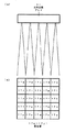
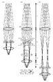
図11に、レーザアレイ34から光記録媒体33までの複数ビームの光路を模式的に示す。図11の(a)、(b)、(c)は、互いに異なる状態を示しており、それぞれにおいて、コリメータレンズ38、開口40a〜40iのうちいずれか一つ、対物レンズ42a〜42iのうちいずれか一つのみが示されている。レーザアレイ34、光記録媒体33はそれぞれ図の上部、下部に位置している。レーザアレイ34では5つのビーム43a〜43eが生成される。ここで、コリメータレンズ38、対物レンズ42a〜42iの焦点距離をそれぞれfc、foとすると、レーザアレイ34からコリメータレンズ38までの光路長はfc、対物レンズ42a〜42iから光記録媒体33までの光路長はfoである。また、開口40a〜40iはそれぞれ対物レンズ42a〜42iの前側焦点位置に設けられているため、開口40a〜40iから対物レンズ42a〜42iまでの光路長はfoである。
FIG. 11 schematically shows a plurality of beam optical paths from the
図11の(b)は、コリメータレンズ38の後側焦点位置と対物レンズ42a〜42iの前側焦点位置とが一致している状態、すなわちコリメータレンズ38から開口40a〜40iまでの光路長がfcである状態を示している。このとき、開口40a〜40iの位置において、ビーム43a〜43eの光軸は一点で交わる。このため、開口40a〜40iの開口直径をdとすると、開口40a〜40iを透過したビーム43a〜43eの直径はいずれもdとなる。従って、対物レンズ42a〜42iのビーム43a〜43eに対する開口数はいずれもd/2foとなる。 FIG. 11B shows a state in which the rear focal position of the collimator lens 38 and the front focal positions of the objective lenses 42a to 42i coincide, that is, the optical path length from the collimator lens 38 to the openings 40a to 40i is fc. It shows a certain state. At this time, at the positions of the openings 40a to 40i, the optical axes of the beams 43a to 43e intersect at one point. For this reason, if the opening diameter of the openings 40a to 40i is d, the diameters of the beams 43a to 43e transmitted through the openings 40a to 40i are all d. Accordingly, the numerical apertures of the objective lenses 42a to 42i with respect to the beams 43a to 43e are all d / 2fo.
図11の(a)は、コリメータレンズ38の後側焦点位置が対物レンズ42a〜42iの前側焦点位置に対して対物レンズ42a〜42iの側へずれている状態、すなわちコリメータレンズ38から開口40a〜40iまでの光路長がfcより短い状態を示している。このとき、開口40a〜40iの位置において、ビーム43a、43bの光軸はビーム43cの光軸に対して図の左側へずれ、ビーム43d、43eの光軸はビーム43cの光軸に対して図の右側へずれる。このため、開口40a〜40iの開口直径をdとすると、開口40a〜40iを透過したビーム43cの直径はdとなるが、ビーム43a、43bは開口40a〜40iで図の左側の部分が蹴られ、ビーム43d、43eは開口40a〜40iで図の右側の部分が蹴られるため、開口40a〜40iを透過したビーム43a、43b、43d、43eの直径はdより小さくなる。従って、対物レンズ42a〜42iのビーム43cに対する開口数はd/2foとなるが、ビーム43a、43b、43d、43eに対する開口数はd/2foより小さくなる。 11A shows a state in which the rear focal position of the collimator lens 38 is shifted toward the objective lenses 42a to 42i with respect to the front focal positions of the objective lenses 42a to 42i, that is, from the collimator lens 38 to the openings 40a to 40a. The optical path length up to 40i is shorter than fc. At this time, at the positions of the openings 40a to 40i, the optical axes of the beams 43a and 43b are shifted to the left in the drawing with respect to the optical axis of the beam 43c, and the optical axes of the beams 43d and 43e are illustrated with respect to the optical axis of the beam 43c. To the right. For this reason, if the opening diameter of the openings 40a to 40i is d, the diameter of the beam 43c transmitted through the openings 40a to 40i is d, but the beams 43a and 43b are kicked by the openings 40a to 40i on the left side of the figure. Since the beams 43d and 43e are kicked at the right side of the drawing by the openings 40a to 40i, the diameters of the beams 43a, 43b, 43d and 43e transmitted through the openings 40a to 40i are smaller than d. Accordingly, the numerical aperture for the beam 43c of the objective lenses 42a to 42i is d / 2fo, but the numerical aperture for the beams 43a, 43b, 43d, and 43e is smaller than d / 2fo.
図11の(c)は、コリメータレンズ38の後側焦点位置が対物レンズ42a〜42iの前側焦点位置に対してコリメータレンズ38の側へずれている状態、すなわちコリメータレンズ38から開口40a〜40iまでの光路長がfcより長い状態を示している。このとき、開口40a〜40iの位置において、ビーム43a、43bの光軸はビーム43cの光軸に対して図の右側へずれ、ビーム43d、43eの光軸はビーム43cの光軸に対して図の左側へずれる。このため、開口40a〜40iの開口直径をdとすると、開口40a〜40iを透過したビーム43cの直径はdとなるが、ビーム43a、43bは開口40a〜40iで図の右側の部分が蹴られ、ビーム43d、43eは開口40a〜40iで図の左側の部分が蹴られるため、開口40a〜40iを透過したビーム43a、43b、43d、43eの直径はdより小さくなる。従って、対物レンズ42a〜42iのビーム43cに対する開口数はd/2foとなるが、ビーム43a、43b、43d、43eに対する開口数はd/2foより小さくなる。 FIG. 11C shows a state in which the rear focal position of the collimator lens 38 is shifted toward the collimator lens 38 with respect to the front focal position of the objective lenses 42a to 42i, that is, from the collimator lens 38 to the openings 40a to 40i. The optical path length of is longer than fc. At this time, at the positions of the openings 40a to 40i, the optical axes of the beams 43a and 43b are shifted to the right in the drawing with respect to the optical axis of the beam 43c, and the optical axes of the beams 43d and 43e are illustrated with respect to the optical axis of the beam 43c. Shift to the left side of Therefore, if the opening diameter of the openings 40a to 40i is d, the diameter of the beam 43c transmitted through the openings 40a to 40i is d, but the beams 43a and 43b are kicked at the right side of the figure by the openings 40a to 40i. Since the beams 43d and 43e are kicked at the left side of the drawing by the openings 40a to 40i, the diameters of the beams 43a, 43b, 43d and 43e transmitted through the openings 40a to 40i are smaller than d. Accordingly, the numerical aperture for the beam 43c of the objective lenses 42a to 42i is d / 2fo, but the numerical aperture for the beams 43a, 43b, 43d, and 43e is smaller than d / 2fo.
ここで、図10に示す参考例の光学ユニットにおいて、コリメータレンズ38から開口41e[光学ユニットの上面から見て、3×3マトリックス配列の中央部に位置する開口]までの光路長がfcであるとする。このとき、コリメータレンズ38から開口41c[光学ユニットの上面から見て、3×3マトリックス配列の右上部に位置する開口]、41g[光学ユニットの上面から見て、3×3マトリックス配列の左下部に位置する開口]までの光路長はfcである。すなわち、対物レンズ42c、42e、42gが選択された場合のレーザアレイ34から光記録媒体33までの複数ビームの光路は図11(b)に示す通りである。従って、対物レンズ42c、42e、42gが選択された場合、対物レンズ42c、42e、42gのビーム43a〜43eに対する開口数はいずれもd/2foとなる。これに対し、コリメータレンズ38から開口41a、41b、41d[光学ユニットの上面から見て、それぞれ3×3マトリックス配列の左上部、中央上部、左中央部に位置する開口]までの光路長はfcより短く、コリメータレンズ38から開口41f、41h、41i[光学ユニットの上面から見て、それぞれ3×3マトリックス配列の右中央部、中央下部、右下部に位置する開口]までの光路長はfcより長い。すなわち、対物レンズ42a、42b、42dが選択された場合のレーザアレイ34から光記録媒体33までの複数ビームの光路は図11(a)に示す通りであり、対物レンズ42f、42h、42iが選択された場合のレーザアレイ34から光記録媒体33までの複数ビームの光路は図11(c)に示す通りである。従って、対物レンズ42a、42b、42d、42f、42h、42iが選択された場合、それらのビーム43cに対する開口数はd/2foとなるが、ビーム43a、43b、43d、43eに対する開口数はd/2foより小さくなる。
Here, in the optical unit of the reference example shown in FIG. 10, the optical path length from the collimator lens 38 to the opening 41e [the opening located at the center of the 3 × 3 matrix arrangement when viewed from the top surface of the optical unit] is fc. And At this time, the aperture 41c from the collimator lens 38 [opening located at the upper right portion of the 3 × 3 matrix arrangement when viewed from the upper surface of the optical unit], 41 g [lower left portion of the 3 × 3 matrix arrangement when viewed from the upper surface of the optical unit] The optical path length to the opening located at fc is fc. That is, the optical paths of a plurality of beams from the
上述のように、対物レンズの開口数が小さくなると、対物レンズにより光記録媒体内に形成される集光スポットの径が大きくなり、記録時の感度の低下および再生時の分解能の低下が生じるため、光記録媒体に対する情報記録再生の品質が低下する。 As described above, when the numerical aperture of the objective lens is reduced, the diameter of the focused spot formed in the optical recording medium by the objective lens is increased, resulting in lower sensitivity during recording and lower resolution during reproduction. Therefore, the quality of information recording / reproduction with respect to the optical recording medium is deteriorated.
以上の参考例を参照し、以下、本発明の実施形態を説明する。 Hereinafter, embodiments of the present invention will be described with reference to the above reference examples.
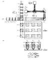
図1に、本発明の光学ユニットの一実施形態を示す。本実施形態は、光記録媒体に対し、複数の対物レンズを選択的に用いると共に、複数のビームを用いて並列に情報の記録再生を行う光学ユニットの実施の形態である。図の(a)、(b)はそれぞれ上面図、側面図である。光記録媒体2はカード状である。光学ユニットは、複数のビームを生成するレーザアレイ3と、複数のビームを受光する光検出器アレイ4と、選択的に用いられる9個の対物レンズ11a〜11iとを有する。ここで、レーザアレイ3は光源部であり、光検出器アレイ4は光検出部である。
FIG. 1 shows an embodiment of the optical unit of the present invention. This embodiment is an embodiment of an optical unit that selectively uses a plurality of objective lenses with respect to an optical recording medium and records and reproduces information in parallel using a plurality of beams. (A), (b) of a figure is a top view and a side view, respectively. The
対物レンズ11a〜11iは、光記録媒体2から所要距離隔てられて3×3のマトリックス状に配列されており、それぞれ光路切替素子8c、光路切替素子8d、ミラー6d、光路切替素子8e、光路切替素子8f、ミラー6e、光路切替素子8g、光路切替素子8h、ミラー6fの下に位置している。対物レンズ11a〜11iの上には、それぞれ開口9a〜9i、1/4波長板10a〜10iが設けられている。開口9a〜9iはそれぞれ対物レンズ11a〜11iの前側焦点位置に設けられている。光学ユニットの上面から見て、光記録媒体2の左上部、中央上部、右上部、左中央部、中央部、右中央部、左下部、中央下部、右下部に対して情報の記録再生を行う場合、それぞれ対物レンズ11a〜11iが選択される。
The objective lenses 11a to 11i are arranged in a 3 × 3 matrix at a required distance from the
ここで、対物レンズ11a〜11iは、3×3マトリックス配列の2方向に関して、同一のピッチで正方格子状に配列されている。また、光路切替素子8a、光路切替素子8c、光路切替素子8d、ミラー6d、光路切替素子8b、光路切替素子8e、光路切替素子8f、ミラー6e、ミラー6c、光路切替素子8g、光路切替素子8h、ミラー6fも、上記2方向に関して、同一のピッチで正方格子状に配列されている。 Here, the objective lenses 11a to 11i are arranged in a square lattice pattern at the same pitch in the two directions of the 3 × 3 matrix arrangement. The optical path switching element 8a, the optical path switching element 8c, the optical path switching element 8d, the mirror 6d, the optical path switching element 8b, the optical path switching element 8e, the optical path switching element 8f, the mirror 6e, the mirror 6c, the optical path switching element 8g, and the optical path switching element 8h. The mirrors 6f are also arranged in a square lattice at the same pitch in the two directions.
例えば、光記録媒体2の面積が60mm×60mmであり、光記録媒体2の面内の2方向(対物レンズ11a〜11iのマトリックス配列の配列方向)における対物レンズ11a〜11iの配列ピッチが20mmであるとする。このとき、対物レンズ11a〜11iのそれぞれにより光記録媒体2内に形成される集光スポットが、光記録媒体2のデータ領域の一部である20mm×20mmの範囲内を走査すれば良い。このため、光記録媒体2を、光記録媒体2の面内の2方向へ20mm×20mmの範囲内で移動させれば良い。従って、光記録媒体2を移動させるための機構を小型化することができる。
For example, the area of the
ミラー6c〜6f、光路切替素子8a〜8hは、対物レンズ11a〜11iのうちいずれか一つの対物レンズを選択したとき、レーザアレイ3で生成された複数のビームが選択対物レンズを介して光記録媒体2へ導かれ、光記録媒体2で反射された複数のビームが選択対物レンズを介して光検出器アレイ4へ導かれるように、レーザアレイ3から対物レンズ11a〜11iまでの複数の光路(往路光路)および対物レンズ11a〜11iから光検出器アレイ4までの複数の光路(復路光路)を切り替える。光路切替素子8a〜8hは電気的に駆動され、入射光を透過させるか反射するかを切り替え可能である。ここで、ミラー6c〜6f、光路切替素子8a〜8hは光路切替部を構成する。
When any one of the objective lenses 11a to 11i is selected, the mirrors 6c to 6f and the optical path switching elements 8a to 8h optically record a plurality of beams generated by the
偏光ビームスプリッタ5b、1/4波長板10j、10k、可変ミラー12a〜12h、ミラー13a、13bは、対物レンズ11a〜11iのうちどの対物レンズを選択しても、レーザアレイ3から選択対物レンズまでの往路(往路光路)の光路長および選択対物レンズから光検出器アレイ4までの復路(復路光路)の光路長のそれぞれが実質的に一定になる(すなわち全ての対物レンズに関して均一化する)ように、往路の光路長および復路の光路長を補正する。可変ミラー12a〜12hは電気的に駆動され、入射光を透過させるか反射するかを切り替え可能である。ここで、偏光ビームスプリッタ5b、1/4波長板10j、10k、可変ミラー12a〜12h、ミラー13a、13bは光路長補正部を構成する。光路長補正部は、往路の光路長を補正する往路用光路長補正部と復路の光路長を補正する復路用光路長補正部とを有する。1/4波長板10j、可変ミラー12a〜12d、ミラー13aが往路用光路長補正部を構成し、1/4波長板10k、可変ミラー12e〜12h、ミラー13bが復路用光路長補正部を構成する。
The polarizing beam splitter 5b, the quarter-
レーザアレイ3で生成された複数のビームは、偏光ビームスプリッタ5aへP偏光として入射してほぼ100%が透過し、ミラー6a、6bで反射され、コリメータレンズ7を透過して発散光から平行光へ変換され、光路長補正部、光路切替部を経た後、開口9a〜9iのうちいずれか一つを透過し、1/4波長板10a〜10iのうちいずれか一つを透過して直線偏光から円偏光へ変換され、対物レンズ11a〜11iのうちいずれか一つを透過して平行光から収束光へ変換され、光記録媒体2内に集光される。光記録媒体2で反射された複数のビームは、対物レンズ11a〜11iのうちいずれか一つを逆向きに透過して発散光から平行光へ変換され、1/4波長板10a〜10iのうちいずれか一つを透過して円偏光から直線偏光へ変換され、開口9a〜9iのうちいずれか一つを透過し、光路切替部、光路長補正部を経た後、コリメータレンズ7を逆向きに透過して平行光から収束光へ変換され、ミラー6b、6aで反射され、偏光ビームスプリッタ5aへS偏光として入射してほぼ100%が反射され、光検出器アレイ4で受光される。
The plurality of beams generated by the
対物レンズ11aが選択された場合、光路切替素子8a、8cは入射光を反射する。また、可変ミラー12a〜12hは入射光を透過させる。レーザアレイ3で生成された複数のビームは偏光ビームスプリッタ5bへP偏光として入射してほぼ100%が透過し、1/4波長板10jを透過して直線偏光から円偏光へ変換され、可変ミラー12a〜12dを透過し、ミラー13aで反射され、可変ミラー12d〜12aを透過し、1/4波長板10jを透過して円偏光から直線偏光へ変換され、偏光ビームスプリッタ5bへS偏光として入射してほぼ100%が反射される。これらの複数のビームは光路切替素子8a、8cで反射され、対物レンズ11aを介して光記録媒体2へ導かれる。
When the objective lens 11a is selected, the optical path switching elements 8a and 8c reflect incident light. Further, the variable mirrors 12a to 12h transmit incident light. The plurality of beams generated by the
光記録媒体2で反射された複数のビームは対物レンズ11aを介し、光路切替素子8c、8aで反射される。これらの複数のビームは偏光ビームスプリッタ5bへP偏光として入射してほぼ100%が透過し、1/4波長板10kを透過して直線偏光から円偏光へ変換され、可変ミラー12e〜12hを透過し、ミラー13bで反射され、可変ミラー12h〜12eを透過し、1/4波長板10kを透過して円偏光から直線偏光へ変換され、偏光ビームスプリッタ5bへS偏光として入射してほぼ100%が反射され、光検出器アレイ4へ導かれる。
The plurality of beams reflected by the
対物レンズ11bが選択された場合、光路切替素子8cは入射光を透過させ、光路切替素子8a、8dは入射光を反射する。また、可変ミラー12a〜12c、12e〜12gは入射光を透過させ、可変ミラー12d、12hは入射光を反射する。レーザアレイ3で生成された複数のビームは偏光ビームスプリッタ5bへP偏光として入射してほぼ100%が透過し、1/4波長板10jを透過して直線偏光から円偏光へ変換され、可変ミラー12a〜12cを透過し、可変ミラー12dで反射され、可変ミラー12c〜12aを透過し、1/4波長板10jを透過して円偏光から直線偏光へ変換され、偏光ビームスプリッタ5bへS偏光として入射してほぼ100%が反射される。これらの複数のビームは光路切替素子8aで反射され、光路切替素子8cを透過し、光路切替素子8dで反射され、対物レンズ11bを介して光記録媒体2へ導かれる。
When the objective lens 11b is selected, the optical path switching element 8c transmits incident light, and the optical path switching elements 8a and 8d reflect incident light. The variable mirrors 12a to 12c and 12e to 12g transmit incident light, and the variable mirrors 12d and 12h reflect incident light. The plurality of beams generated by the
光記録媒体2で反射された複数のビームは対物レンズ11bを介し、光路切替素子8dで反射され、光路切替素子8cを透過し、光路切替素子8aで反射される。これらの複数のビームは偏光ビームスプリッタ5bへP偏光として入射してほぼ100%が透過し、1/4波長板10kを透過して直線偏光から円偏光へ変換され、可変ミラー12e〜12gを透過し、可変ミラー12hで反射され、可変ミラー12g〜12eを透過し、1/4波長板10kを透過して円偏光から直線偏光へ変換され、偏光ビームスプリッタ5bへS偏光として入射してほぼ100%が反射され、光検出器アレイ4へ導かれる。
The plurality of beams reflected by the
対物レンズ11cが選択された場合、光路切替素子8c、8dは入射光を透過させ、光路切替素子8aは入射光を反射する。また、可変ミラー12a、12b、12e、12fは入射光を透過させ、可変ミラー12c、12gは入射光を反射する。レーザアレイ3で生成された複数のビームは偏光ビームスプリッタ5bへP偏光として入射してほぼ100%が透過し、1/4波長板10jを透過して直線偏光から円偏光へ変換され、可変ミラー12a、12bを透過し、可変ミラー12cで反射され、可変ミラー12b、12aを透過し、1/4波長板10jを透過して円偏光から直線偏光へ変換され、偏光ビームスプリッタ5bへS偏光として入射してほぼ100%が反射される。これらの複数のビームは光路切替素子8aで反射され、光路切替素子8c、8dを透過し、ミラー6dで反射され、対物レンズ11cを介して光記録媒体2へ導かれる。
When the objective lens 11c is selected, the optical path switching elements 8c and 8d transmit incident light, and the optical path switching element 8a reflects incident light. The variable mirrors 12a, 12b, 12e, and 12f transmit incident light, and the variable mirrors 12c and 12g reflect incident light. The plurality of beams generated by the
光記録媒体2で反射された複数のビームは対物レンズ11cを介し、ミラー6dで反射され、光路切替素子8d、8cを透過し、光路切替素子8aで反射される。これらの複数のビームは偏光ビームスプリッタ5bへP偏光として入射してほぼ100%が透過し、1/4波長板10kを透過して直線偏光から円偏光へ変換され、可変ミラー12e、12fを透過し、可変ミラー12gで反射され、可変ミラー12f、12eを透過し、1/4波長板10kを透過して円偏光から直線偏光へ変換され、偏光ビームスプリッタ5bへS偏光として入射してほぼ100%が反射され、光検出器アレイ4へ導かれる。
The plurality of beams reflected by the
対物レンズ11dが選択された場合、光路切替素子8aは入射光を透過させ、光路切替素子8b、8eは入射光を反射する。また、可変ミラー12a〜12c、12e〜12gは入射光を透過させ、可変ミラー12d、12hは入射光を反射する。レーザアレイ3で生成された複数のビームは偏光ビームスプリッタ5bへP偏光として入射してほぼ100%が透過し、1/4波長板10jを透過して直線偏光から円偏光へ変換され、可変ミラー12a〜12cを透過し、可変ミラー12dで反射され、可変ミラー12c〜12aを透過し、1/4波長板10jを透過して円偏光から直線偏光へ変換され、偏光ビームスプリッタ5bへS偏光として入射してほぼ100%が反射される。これらの複数のビームは光路切替素子8aを透過し、光路切替素子8b、8eで反射され、対物レンズ11dを介して光記録媒体2へ導かれる。
When the objective lens 11d is selected, the optical path switching element 8a transmits the incident light, and the optical path switching elements 8b and 8e reflect the incident light. The variable mirrors 12a to 12c and 12e to 12g transmit incident light, and the variable mirrors 12d and 12h reflect incident light. The plurality of beams generated by the
光記録媒体2で反射された複数のビームは対物レンズ11dを介し、光路切替素子8e、8bで反射され、光路切替素子8aを透過する。これらの複数のビームは偏光ビームスプリッタ5bへP偏光として入射してほぼ100%が透過し、1/4波長板10kを透過して直線偏光から円偏光へ変換され、可変ミラー12e〜12gを透過し、可変ミラー12hで反射され、可変ミラー12g〜12eを透過し、1/4波長板10kを透過して円偏光から直線偏光へ変換され、偏光ビームスプリッタ5bへS偏光として入射してほぼ100%が反射され、光検出器アレイ4へ導かれる。
The plurality of beams reflected by the
対物レンズ11eが選択された場合、光路切替素子8a、8eは入射光を透過させ、光路切替素子8b、8fは入射光を反射する。また、可変ミラー12a、12b、12e、12fは入射光を透過させ、可変ミラー12c、12gは入射光を反射する。レーザアレイ3で生成された複数のビームは偏光ビームスプリッタ5bへP偏光として入射してほぼ100%が透過し、1/4波長板10jを透過して直線偏光から円偏光へ変換され、可変ミラー12a、12bを透過し、可変ミラー12cで反射され、可変ミラー12b、12aを透過し、1/4波長板10jを透過して円偏光から直線偏光へ変換され、偏光ビームスプリッタ5bへS偏光として入射してほぼ100%が反射される。これらの複数のビームは光路切替素子8aを透過し、光路切替素子8bで反射され、光路切替素子8eを透過し、光路切替素子8fで反射され、対物レンズ11eを介して光記録媒体2へ導かれる。
When the objective lens 11e is selected, the optical path switching elements 8a and 8e transmit incident light, and the optical path switching elements 8b and 8f reflect incident light. The variable mirrors 12a, 12b, 12e, and 12f transmit incident light, and the variable mirrors 12c and 12g reflect incident light. The plurality of beams generated by the
光記録媒体2で反射された複数のビームは対物レンズ11eを介し、光路切替素子8fで反射され、光路切替素子8eを透過し、光路切替素子8bで反射され、光路切替素子8aを透過する。これらの複数のビームは偏光ビームスプリッタ5bへP偏光として入射してほぼ100%が透過し、1/4波長板10kを透過して直線偏光から円偏光へ変換され、可変ミラー12e、12fを透過し、可変ミラー12gで反射され、可変ミラー12f、12eを透過し、1/4波長板10kを透過して円偏光から直線偏光へ変換され、偏光ビームスプリッタ5bへS偏光として入射してほぼ100%が反射され、光検出器アレイ4へ導かれる。
The plurality of beams reflected by the
対物レンズ11fが選択された場合、光路切替素子8a、8e、8fは入射光を透過させ、光路切替素子8bは入射光を反射する。また、可変ミラー12a、12eは入射光を透過させ、可変ミラー12b、12fは入射光を反射する。レーザアレイ3で生成された複数のビームは偏光ビームスプリッタ5bへP偏光として入射してほぼ100%が透過し、1/4波長板10jを透過して直線偏光から円偏光へ変換され、可変ミラー12aを透過し、可変ミラー12bで反射され、可変ミラー12aを透過し、1/4波長板10jを透過して円偏光から直線偏光へ変換され、偏光ビームスプリッタ5bへS偏光として入射してほぼ100%が反射される。これらの複数のビームは光路切替素子8aを透過し、光路切替素子8bで反射され、光路切替素子8e、8fを透過し、ミラー6eで反射され、対物レンズ11fを介して光記録媒体2へ導かれる。
When the objective lens 11f is selected, the optical path switching elements 8a, 8e, and 8f transmit incident light, and the optical path switching element 8b reflects incident light. The variable mirrors 12a and 12e transmit incident light, and the variable mirrors 12b and 12f reflect incident light. The plurality of beams generated by the
光記録媒体2で反射された複数のビームは対物レンズ11fを介し、ミラー6eで反射され、光路切替素子8f、8eを透過し、光路切替素子8bで反射され、光路切替素子8aを透過する。これらの複数のビームは偏光ビームスプリッタ5bへP偏光として入射してほぼ100%が透過し、1/4波長板10kを透過して直線偏光から円偏光へ変換され、可変ミラー12eを透過し、可変ミラー12fで反射され、可変ミラー12eを透過し、1/4波長板10kを透過して円偏光から直線偏光へ変換され、偏光ビームスプリッタ5bへS偏光として入射してほぼ100%が反射され、光検出器アレイ4へ導かれる。
The plurality of beams reflected by the
対物レンズ11gが選択された場合、光路切替素子8a、8bは入射光を透過させ、光路切替素子8gは入射光を反射する。また、可変ミラー12a、12b、12e、12fは入射光を透過させ、可変ミラー12c、12gは入射光を反射する。レーザアレイ3で生成された複数のビームは偏光ビームスプリッタ5bへP偏光として入射してほぼ100%が透過し、1/4波長板10jを透過して直線偏光から円偏光へ変換され、可変ミラー12a、12bを透過し、可変ミラー12cで反射され、可変ミラー12b、12aを透過し、1/4波長板10jを透過して円偏光から直線偏光へ変換され、偏光ビームスプリッタ5bへS偏光として入射してほぼ100%が反射される。これらの複数のビームは光路切替素子8a、8bを透過し、ミラー6c、光路切替素子8gで反射され、対物レンズ11gを介して光記録媒体2へ導かれる。
When the objective lens 11g is selected, the optical path switching elements 8a and 8b transmit incident light, and the optical path switching element 8g reflects incident light. The variable mirrors 12a, 12b, 12e, and 12f transmit incident light, and the variable mirrors 12c and 12g reflect incident light. The plurality of beams generated by the
光記録媒体2で反射された複数のビームは対物レンズ11gを介し、光路切替素子8g、ミラー6cで反射され、光路切替素子8b、8aを透過する。これらの複数のビームは偏光ビームスプリッタ5bへP偏光として入射してほぼ100%が透過し、1/4波長板10kを透過して直線偏光から円偏光へ変換され、可変ミラー12e、12fを透過し、可変ミラー12gで反射され、可変ミラー12f、12eを透過し、1/4波長板10kを透過して円偏光から直線偏光へ変換され、偏光ビームスプリッタ5bへS偏光として入射してほぼ100%が反射され、光検出器アレイ4へ導かれる。
The plurality of beams reflected by the
対物レンズ11hが選択された場合、光路切替素子8a、8b、8gは入射光を透過させ、光路切替素子8hは入射光を反射する。また、可変ミラー12a、12eは入射光を透過させ、可変ミラー12b、12fは入射光を反射する。レーザアレイ3で生成された複数のビームは偏光ビームスプリッタ5bへP偏光として入射してほぼ100%が透過し、1/4波長板10jを透過して直線偏光から円偏光へ変換され、可変ミラー12aを透過し、可変ミラー12bで反射され、可変ミラー12aを透過し、1/4波長板10jを透過して円偏光から直線偏光へ変換され、偏光ビームスプリッタ5bへS偏光として入射してほぼ100%が反射される。これらの複数のビームは光路切替素子8a、8bを透過し、ミラー6cで反射され、光路切替素子8gを透過し、光路切替素子8hで反射され、対物レンズ11hを介して光記録媒体2へ導かれる。
When the objective lens 11h is selected, the optical path switching elements 8a, 8b, and 8g transmit incident light, and the optical path switching element 8h reflects incident light. The variable mirrors 12a and 12e transmit incident light, and the variable mirrors 12b and 12f reflect incident light. The plurality of beams generated by the
光記録媒体2で反射された複数のビームは対物レンズ11hを介し、光路切替素子8hで反射され、光路切替素子8gを透過し、ミラー6cで反射され、光路切替素子8b、8aを透過する。これらの複数のビームは偏光ビームスプリッタ5bへP偏光として入射してほぼ100%が透過し、1/4波長板10kを透過して直線偏光から円偏光へ変換され、可変ミラー12eを透過し、可変ミラー12fで反射され、可変ミラー12eを透過し、1/4波長板10kを透過して円偏光から直線偏光へ変換され、偏光ビームスプリッタ5bへS偏光として入射してほぼ100%が反射され、光検出器アレイ4へ導かれる。
The plurality of beams reflected by the
対物レンズ11iが選択された場合、光路切替素子8a、8b、8g、8hは入射光を透過させる。また、可変ミラー12a、12eは入射光を反射する。レーザアレイ3で生成された複数のビームは偏光ビームスプリッタ5bへP偏光として入射してほぼ100%が透過し、1/4波長板10jを透過して直線偏光から円偏光へ変換され、可変ミラー12aで反射され、1/4波長板10jを透過して円偏光から直線偏光へ変換され、偏光ビームスプリッタ5bへS偏光として入射してほぼ100%が反射される。これらの複数のビームは光路切替素子8a、8bを透過し、ミラー6cで反射され、光路切替素子8g、8hを透過し、ミラー6fで反射され、対物レンズ11iを介して光記録媒体2へ導かれる。
When the objective lens 11i is selected, the optical path switching elements 8a, 8b, 8g, and 8h transmit incident light. The variable mirrors 12a and 12e reflect incident light. The plurality of beams generated by the
光記録媒体2で反射された複数のビームは対物レンズ11iを介し、ミラー6fで反射され、光路切替素子8h、8gを透過し、ミラー6cで反射され、光路切替素子8b、8aを透過する。これらの複数のビームは偏光ビームスプリッタ5bへP偏光として入射してほぼ100%が透過し、1/4波長板10kを透過して直線偏光から円偏光へ変換され、可変ミラー12eで反射され、1/4波長板10kを透過して円偏光から直線偏光へ変換され、偏光ビームスプリッタ5bへS偏光として入射してほぼ100%が反射され、光検出器アレイ4へ導かれる。
The plurality of beams reflected by the
可変ミラー12a〜12d、ミラー13aの配列ピッチおよび可変ミラー12e〜12h、ミラー13bの配列ピッチは、いずれも光記録媒体2の面内の2方向における対物レンズ11a〜11iの配列ピッチの半分に設定されている。これにより、対物レンズ11a〜11iのうちどの対物レンズを選択する場合であっても、レーザアレイ3から選択された対物レンズまでの往路の光路長および選択された対物レンズから光検出器アレイ4までの復路の光路長を均一化し実質的に一定にすることができる。
The arrangement pitch of the variable mirrors 12 a to 12 d and the mirror 13 a and the arrangement pitch of the variable mirrors 12 e to 12 h and the
ここで、コリメータレンズ7、対物レンズ11a〜11iの焦点距離をそれぞれfc、foとすると、レーザアレイ3からコリメータレンズ7までの光路長はfc、対物レンズ11a〜11iから光記録媒体2までの光路長はfoである。また、開口9a〜9iはそれぞれ対物レンズ11a〜11iの前側焦点位置に設けられているため、開口9a〜9iから対物レンズ11a〜11iまでの光路長はfoである。光路切替素子および可変ミラーを前述のように動作させることで、対物レンズ11a〜11iのうちどの対物レンズが選択されても、コリメータレンズ7の後側焦点位置と対物レンズ11a〜11iの前側焦点位置とを一致させる、すなわちコリメータレンズ7から開口9a〜9iまでの光路長をfcとすることができる。すなわち、対物レンズ11a〜11iのうちどの対物レンズが選択された場合も、レーザアレイ3から光記録媒体2までの複数ビームの光路は図11(b)に示すものと同じになり、開口9a〜9iの位置において、レーザアレイ3で生成される複数のビームの光軸は一点で交わる。このため、開口9a〜9iの直径をdとすると、開口9a〜9iを透過した複数のビームの直径はいずれもdとなる。従って、対物レンズ11a〜11iのうちどの対物レンズが選択された場合も、対物レンズ11a〜11iの複数のビームに対する開口数はいずれもd/2foとなり、複数の光ビームに対する対物レンズ開口数の均一化が図られ、全てのビームに対する開口数が常に実質的に一定となる。
Here, if the focal lengths of the
対物レンズの開口数が常に実質的に一定であると、対物レンズにより光記録媒体内に形成される集光スポットの径が常に実質的に一定であり、記録時の感度の低下および再生時の分解能の低下が生じないため、光記録媒体に対する情報記録再生の品質が向上し、光記録媒体に対して正しく情報の記録再生を行うことができる。 When the numerical aperture of the objective lens is always substantially constant, the diameter of the focused spot formed in the optical recording medium by the objective lens is always substantially constant. Since the resolution does not decrease, the quality of information recording / reproducing with respect to the optical recording medium is improved, and information can be correctly recorded / reproduced with respect to the optical recording medium.
図2にレーザアレイ3の構成を示す。図2の(a)、(b)はそれぞれ側面図、上面図である。レーザアレイ3は5行5列に配列された25個の発光部14a〜14yを有し、25個のビームを生成する。発光部14a〜14yのそれぞれからは対応するビームが発散光として出射する。レーザアレイ3の面内の2方向における発光部14a〜14yの配列ピッチは例えば50μmである。光記録媒体2への情報の記録時には、発光部14a〜14yのそれぞれから出射するビームは、ビットデータ“1”を記録する際には高いパワー(例えば100mW)を有しており、ビットデータ“0”を記録する際には低いパワー(例えば50mW)を有している。一方、光記録媒体2からの情報の再生時には、発光部14a〜14yのそれぞれから出射するビームは一定のパワー(例えば10mW)を有している。なお、光源部としては、レーザアレイ3の代わりに単一のレーザと空間光変調器とを組み合わせて複数ビームを作成するようにしたものを用いることも可能である。
FIG. 2 shows the configuration of the
図3に光記録媒体2の構成および光記録媒体2内の集光スポットを示す。図の(a)、(b)はそれぞれ側面図、上面図である。光記録媒体2は2枚の基板の間に記録層15が挟まれた構成である。記録層15の材料としては相変化材料、有機色素材料等が用いられる。レーザアレイ3で生成された25個のビームは対物レンズ11a〜11iにより光記録媒体2内の記録層15上に集光され、5行5列に配列された25個の集光点16a〜16yに25個の集光スポットを形成する。集光点16a〜16yに形成される集光スポットは、それぞれレーザアレイ3の発光部14a〜14yから出射したビームに対応している。ここでfc/fo=50であるとすると、光記録媒体2の面内の2方向における集光点16a〜16yの配列ピッチは例えば1μmとなる。
FIG. 3 shows the configuration of the
光記録媒体2への情報の記録時には、レーザアレイ3から光記録媒体2までの光学系の効率が例えば10%であるとすると、集光点16a〜16yのそれぞれに形成される集光スポットは、ビットデータ“1”を記録する際には高いパワー(例えば10mW)を有しており、ビットデータ“0”を記録する際には低いパワー(例えば5mW)を有している。光記録媒体2の記録層15には、高いパワーが照射された場合はビットデータ“1”に対応する記録マークが形成され、低いパワーが照射された場合はビットデータ“0”に対応する記録マークが形成される。一方、光記録媒体2からの情報の再生時には、レーザアレイ3から光記録媒体2までの光学系の効率が例えば10%であるとすると、集光点16a〜16yのそれぞれに形成される集光スポットは一定のパワー(例えば1mW)を有している。光記録媒体2の記録層15は25個のビームを反射する。ビットデータ“1”に対応する記録マークの反射率は例えば2%であり、ビットデータ“0”に対応する記録マークの反射率は例えば20%である。このとき、集光点16a〜16yのそれぞれで反射されるビームは、ビットデータ“1”を再生する際には低いパワー(例えば20μW)を有しており、ビットデータ“0”を再生する際には高いパワー(例えば200μW)を有している。
When recording information on the
図4に光検出器アレイ4の構成を示す。図の(a)、(b)はそれぞれ側面図、上面図である。光検出器アレイ4は5行5列に配列された25個の受光部17a〜17yを有し、25個のビームを受光する。受光部17a〜17yのそれぞれへは対応するビームが収束光として入射する。受光部17a〜17yで受光されるビームは、それぞれ光記録媒体2の記録層15上の集光点16a〜16yで反射されたビームに対応している。光検出器アレイ4の面内の2方向における受光部17a〜17yの配列ピッチは例えば50μmである。光記録媒体2からの情報の再生時には、光記録媒体2から光検出器アレイ4までの光学系の効率が例えば50%であるとすると、受光部17a〜17yのそれぞれへ入射するビームは、ビットデータ“1”を再生する際には低いパワー(例えば10μW)を有しており、ビットデータ“0”を再生する際には高いパワー(例えば100μW)を有している。
FIG. 4 shows the configuration of the
このように、光学ユニットに25個のビームを生成するレーザアレイ3と25個のビームを受光する光検出器アレイ4とを設け、25個のビームを用いて光記録媒体2に対して並列に(すなわち同時並行で)情報の記録再生を行うことにより、光記録媒体2に対する情報の記録再生の速度を25倍に向上させることができる。
As described above, the optical unit is provided with the
図5に光路切替素子8a〜8hの構成を示す。光路切替素子8a〜8hは、プリズム18aとプリズム18bとの間に、交互に積層された高分子層19aと液晶層20aとが挟まれた構成である。ここで、高分子層19aと液晶層20aとは液晶ブラッグミラーを構成する。プリズム18a、18bの液晶ブラッグミラー側の面には、液晶ブラッグミラーに交流電圧を印加するための透明電極が形成されている。光路切替素子8a〜8hは、液晶ブラッグミラーへ印加される電圧に応じて、図の左側から入射した光を図の右側へ透過させる機能と、図の左側から入射した光を図の下側へ反射する機能との間で、その機能が切り替わる。 FIG. 5 shows the configuration of the optical path switching elements 8a to 8h. The optical path switching elements 8a to 8h are configured such that alternately stacked polymer layers 19a and liquid crystal layers 20a are sandwiched between the prisms 18a and 18b. Here, the polymer layer 19a and the liquid crystal layer 20a constitute a liquid crystal Bragg mirror. Transparent electrodes for applying an AC voltage to the liquid crystal Bragg mirror are formed on the surfaces of the prisms 18a and 18b on the liquid crystal Bragg mirror side. The optical path switching elements 8a to 8h have a function of transmitting light incident from the left side of the figure to the right side of the figure according to a voltage applied to the liquid crystal Bragg mirror, and light incident from the left side of the figure to the lower side of the figure. The function switches between the reflecting function.
液晶ブラッグミラーはネマチック液晶層から作製される。ネマチック液晶は一軸の屈折率異方性を有しており、光学軸に平行な方向の偏光成分(異常光成分)に対する屈折率をne、光学軸に垂直な方向の偏光成分(常光成分)に対する屈折率をnoとすると、ne>noである。液晶ブラッグミラーの作製時には、ネマチック液晶層の表面側、裏面側からそれぞれ平行光を垂直に入射させ、両者を干渉させてネマチック液晶層の内部に定在波を形成する。このとき、定在波の腹の部分(光強度が強い部分)ではネマチック液晶が重合して高分子層19aとなり、定在波の節の部分(光強度が弱い部分)ではネマチック液晶がそのまま液晶層20aとなる。 The liquid crystal Bragg mirror is made from a nematic liquid crystal layer. Nematic liquid crystal has uniaxial refractive index anisotropy, ne is the refractive index for the polarization component (abnormal light component) in the direction parallel to the optical axis, and it is for the polarization component (normal light component) in the direction perpendicular to the optical axis. If the refractive index is no, ne> no. At the time of manufacturing the liquid crystal Bragg mirror, parallel light is vertically incident from the front side and the back side of the nematic liquid crystal layer, and both are interfered to form a standing wave inside the nematic liquid crystal layer. At this time, the nematic liquid crystal is polymerized in the antinode portion of the standing wave (the portion where the light intensity is strong) to form a polymer layer 19a, and the nematic liquid crystal is the liquid crystal as it is in the node portion of the standing wave (the portion where the light intensity is weak). It becomes the layer 20a.
ここで、高分子層19a、液晶層20aの屈折率をそれぞれnH、nLとする。液晶ブラッグミラーに交流電圧を印加しない場合、高分子層19a、液晶層20aにおけるネマチック液晶は、いずれも光学軸の方向が面内でランダムな方向になるように配向している。このとき、nH、nLはnH=nL=[(2no2+ne2)/3]1/2で与えられる。一方、液晶ブラッグミラーに交流電圧を印加した場合、高分子層19aにおけるネマチック液晶は光学軸の方向が面内でランダムな方向になるように配向したままであるが、液晶層20aにおけるネマチック液晶は光学軸の方向が厚さ方向になるように配向する。このとき、nH、nLはそれぞれnH=[(2no2+ne2)/3]1/2、nL=noで与えられる。 Here, the refractive indexes of the polymer layer 19a and the liquid crystal layer 20a are nH and nL, respectively. When no AC voltage is applied to the liquid crystal Bragg mirror, the nematic liquid crystals in the polymer layer 19a and the liquid crystal layer 20a are both aligned such that the direction of the optical axis is random in the plane. At this time, nH and nL are given by nH = nL = [(2no 2 + ne 2 ) / 3] 1/2 . On the other hand, when an AC voltage is applied to the liquid crystal Bragg mirror, the nematic liquid crystal in the polymer layer 19a remains aligned so that the direction of the optical axis is a random direction in the plane, but the nematic liquid crystal in the liquid crystal layer 20a is The orientation is such that the direction of the optical axis is the thickness direction. At this time, nH and nL are given by nH = [(2no 2 + ne 2 ) / 3] 1/2 and nL = no, respectively.
液晶ブラッグミラーへの入射光の設計波長をλ、入射角をθとし、高分子層19aと液晶層20aとから成る多層構造の周期をpとすると、液晶ブラッグミラーが良好に機能するためにはp=(λ/4nH+λ/4nL)×cosθとする必要がある。例えば、λ=400nm、θ=45°、ne=1.73、no=1.53であるとすると、nH=1.60、nL=1.53となるためp=90nmとなる。高分子層19aと液晶層20aとから成る多層構造の層数は例えば201である。このとき、液晶ブラッグミラーの厚さは約9.0μmとなる。また、液晶層20aにおけるネマチック液晶を光学軸の方向が厚さ方向になるように配向させるために、液晶ブラッグミラーに印加する交流電圧の実効値は140V程度となる。 If the design wavelength of incident light to the liquid crystal Bragg mirror is λ, the incident angle is θ, and the period of the multilayer structure composed of the polymer layer 19a and the liquid crystal layer 20a is p, in order for the liquid crystal Bragg mirror to function well It is necessary that p = (λ / 4nH + λ / 4nL) × cos θ. For example, if λ = 400 nm, θ = 45 °, ne = 1.73, and no = 1.53, then nH = 1.60 and nL = 1.53, so p = 90 nm. The number of layers in the multilayer structure composed of the polymer layer 19a and the liquid crystal layer 20a is, for example, 201. At this time, the thickness of the liquid crystal Bragg mirror is about 9.0 μm. Further, in order to align the nematic liquid crystal in the liquid crystal layer 20a so that the direction of the optical axis is the thickness direction, the effective value of the AC voltage applied to the liquid crystal Bragg mirror is about 140V.
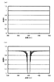
図6に、上記の条件における、光路切替素子8a〜8hへの入射光の波長と光路切替素子8a〜8hの透過率との関係の計算例を示す。図6の(a)は液晶ブラッグミラーに交流電圧を印加しない場合の計算例であり、図6の(b)は液晶ブラッグミラーに交流電圧を印加した場合の計算例である。また、図中の実線、点線はそれぞれP偏光成分、S偏光成分に対する計算例を表している。液晶ブラッグミラーに交流電圧を印加しない場合、図6の(a)に示すように、波長400nmの近傍においては、光路切替素子8a〜8hへの入射光はP偏光成分、S偏光成分ともほぼ100%が透過する。一方、液晶ブラッグミラーに交流電圧を印加した場合、図6の(b)に示すように、波長400nmの近傍においては、光路切替素子8a〜8hへの入射光はP偏光成分、S偏光成分ともほぼ100%が反射される。 FIG. 6 shows a calculation example of the relationship between the wavelength of light incident on the optical path switching elements 8a to 8h and the transmittance of the optical path switching elements 8a to 8h under the above conditions. FIG. 6A is a calculation example when no AC voltage is applied to the liquid crystal Bragg mirror, and FIG. 6B is a calculation example when an AC voltage is applied to the liquid crystal Bragg mirror. In addition, the solid line and the dotted line in the figure represent calculation examples for the P-polarized component and the S-polarized component, respectively. In the case where no AC voltage is applied to the liquid crystal Bragg mirror, as shown in FIG. 6A, in the vicinity of the wavelength of 400 nm, the incident light to the optical path switching elements 8a to 8h is almost 100 for both the P-polarized component and the S-polarized component. % Is transmitted. On the other hand, when an AC voltage is applied to the liquid crystal Bragg mirror, as shown in FIG. 6B, in the vicinity of the wavelength of 400 nm, the incident light to the optical path switching elements 8a to 8h is both P-polarized component and S-polarized component. Almost 100% is reflected.
図7に可変ミラー12a〜12hの構成を示す。可変ミラー12a〜12hは、基板21aと基板21bとの間に、交互に積層された高分子層19bと液晶層20bとが挟まれた構成である。ここで、高分子層19bと液晶層20bとは液晶ブラッグミラーを構成する。基板21a、21bの液晶ブラッグミラー側の面には、液晶ブラッグミラーに交流電圧を印加するための透明電極が形成されている。可変ミラー12a〜12hは、液晶ブラッグミラーへ印加される電圧に応じて、図の上側から入射した光を図の下側へ透過させる機能と、図の上側から入射した光を図の上側へ反射する機能との間で、その機能が切り替わる。
FIG. 7 shows the configuration of the variable mirrors 12a to 12h. The variable mirrors 12a to 12h are configured such that alternately stacked polymer layers 19b and liquid crystal layers 20b are sandwiched between a
液晶ブラッグミラーはネマチック液晶層から作製される。ネマチック液晶は一軸の屈折率異方性を有しており、光学軸に平行な方向の偏光成分(異常光成分)に対する屈折率をne、光学軸に垂直な方向の偏光成分(常光成分)に対する屈折率をnoとすると、ne>noである。液晶ブラッグミラーの作製時には、ネマチック液晶層の表面側、裏面側からそれぞれ平行光を垂直に入射させ、両者を干渉させてネマチック液晶層の内部に定在波を形成する。このとき、定在波の腹の部分(光強度が強い部分)ではネマチック液晶が重合して高分子層19bとなり、定在波の節の部分(光強度が弱い部分)ではネマチック液晶がそのまま液晶層20bとなる。 The liquid crystal Bragg mirror is made from a nematic liquid crystal layer. Nematic liquid crystal has uniaxial refractive index anisotropy, ne is the refractive index for the polarization component (abnormal light component) in the direction parallel to the optical axis, and it is for the polarization component (normal light component) in the direction perpendicular to the optical axis. If the refractive index is no, ne> no. At the time of manufacturing the liquid crystal Bragg mirror, parallel light is vertically incident from the front side and the back side of the nematic liquid crystal layer, and both are interfered to form a standing wave inside the nematic liquid crystal layer. At this time, the nematic liquid crystal is polymerized at the antinode portion of the standing wave (the portion where the light intensity is strong) to form a polymer layer 19b, and the nematic liquid crystal is the liquid crystal as it is at the node portion of the standing wave (the portion where the light intensity is weak). It becomes the layer 20b.
ここで、高分子層19b、液晶層20bの屈折率をそれぞれnH、nLとする。液晶ブラッグミラーに交流電圧を印加しない場合、高分子層19b、液晶層20bにおけるネマチック液晶は、いずれも光学軸の方向が面内でランダムな方向になるように配向している。このとき、nH、nLはnH=nL=[(2no2+ne2)/3]1/2で与えられる。一方、液晶ブラッグミラーに交流電圧を印加した場合、高分子層19bにおけるネマチック液晶は光学軸の方向が面内でランダムな方向になるように配向したままであるが、液晶層20bにおけるネマチック液晶は光学軸の方向が厚さ方向になるように配向する。このとき、nH、nLはそれぞれnH=[(2no2+ne2)/3]1/2、nL=noで与えられる。 Here, the refractive indexes of the polymer layer 19b and the liquid crystal layer 20b are nH and nL, respectively. When no AC voltage is applied to the liquid crystal Bragg mirror, the nematic liquid crystals in the polymer layer 19b and the liquid crystal layer 20b are both aligned so that the direction of the optical axis is a random direction in the plane. At this time, nH and nL are given by nH = nL = [(2no 2 + ne 2 ) / 3] 1/2 . On the other hand, when an AC voltage is applied to the liquid crystal Bragg mirror, the nematic liquid crystal in the polymer layer 19b remains aligned so that the direction of the optical axis is random in the plane, but the nematic liquid crystal in the liquid crystal layer 20b is The orientation is such that the direction of the optical axis is the thickness direction. At this time, nH and nL are given by nH = [(2no 2 + ne 2 ) / 3] 1/2 and nL = no, respectively.
液晶ブラッグミラーへの入射光の設計波長をλ、入射角をθとし、高分子層19bと液晶層20bとから成る多層構造の周期をpとすると、液晶ブラッグミラーが良好に機能するためにはp=(λ/4nH+λ/4nL)×cosθとする必要がある。例えば、λ=400nm、θ=0°、ne=1.73、no=1.53であるとすると、nH=1.60、nL=1.53となるためp=128nmとなる。高分子層19bと液晶層20bとから成る多層構造の層数は例えば201である。このとき、液晶ブラッグミラーの厚さは約12.8μmとなる。また、液晶層20bにおけるネマチック液晶を光学軸の方向が厚さ方向になるように配向させるために、液晶ブラッグミラーに印加する交流電圧の実効値は200V程度となる。 If the design wavelength of incident light to the liquid crystal Bragg mirror is λ, the incident angle is θ, and the period of the multilayer structure composed of the polymer layer 19b and the liquid crystal layer 20b is p, the liquid crystal Bragg mirror functions well. It is necessary that p = (λ / 4nH + λ / 4nL) × cos θ. For example, if λ = 400 nm, θ = 0 °, ne = 1.73, and no = 1.53, then nH = 1.60 and nL = 1.53, so p = 128 nm. The number of layers in the multilayer structure composed of the polymer layer 19b and the liquid crystal layer 20b is 201, for example. At this time, the thickness of the liquid crystal Bragg mirror is about 12.8 μm. Further, in order to align the nematic liquid crystal in the liquid crystal layer 20b so that the direction of the optical axis is the thickness direction, the effective value of the AC voltage applied to the liquid crystal Bragg mirror is about 200V.
図8に、上記の条件における、可変ミラー12a〜12hへの入射光の波長と可変ミラー12a〜12hの透過率との関係の計算例を示す。図8の(a)は液晶ブラッグミラーに交流電圧を印加しない場合の計算例であり、図8の(b)は液晶ブラッグミラーに交流電圧を印加した場合の計算例である。液晶ブラッグミラーに交流電圧を印加しない場合、図8の(a)に示すように、波長400nmの近傍においては、可変ミラー12a〜12hへの入射光はほぼ100%が透過する。一方、液晶ブラッグミラーに交流電圧を印加した場合、図8の(b)に示すように、波長400nmの近傍においては、可変ミラー12a〜12hへの入射光はほぼ100%が反射される。 FIG. 8 shows a calculation example of the relationship between the wavelength of light incident on the variable mirrors 12a to 12h and the transmittance of the variable mirrors 12a to 12h under the above conditions. FIG. 8A is a calculation example when no AC voltage is applied to the liquid crystal Bragg mirror, and FIG. 8B is a calculation example when an AC voltage is applied to the liquid crystal Bragg mirror. When no AC voltage is applied to the liquid crystal Bragg mirror, as shown in FIG. 8A, almost 100% of incident light to the variable mirrors 12a to 12h is transmitted in the vicinity of the wavelength of 400 nm. On the other hand, when an AC voltage is applied to the liquid crystal Bragg mirror, as shown in FIG. 8B, almost 100% of the incident light to the variable mirrors 12a to 12h is reflected in the vicinity of the wavelength of 400 nm.
図9に、本発明の光学的情報記録再生装置一実施形態を示す。本実施形態の光学的情報記録再生装置において、光学ユニット1は、図1に示す本発明の光学ユニットの実施形態のものと同一である。光記録媒体2はポジショナ22に搭載されている。変調回路24から記録信号生成回路25を経てレーザアレイ駆動回路26までの回路(記録用回路)、増幅回路27から再生信号処理回路28を経て復調回路29までの回路(再生用回路)、光路切替部駆動回路である光路切替素子駆動回路30、光路長補正部駆動回路である可変ミラー駆動回路31、およびポジショナ駆動回路32は、いずれもコントローラ(制御回路)23により制御される。
FIG. 9 shows an embodiment of the optical information recording / reproducing apparatus of the present invention. In the optical information recording / reproducing apparatus of this embodiment, the
ポジショナ駆動回路32は、光記録媒体2への情報の記録時および光記録媒体2からの情報の再生時に、光記録媒体2を、光記録媒体2の記録層15上の集光点16a〜16yの位置に対して光記録媒体2の面内の2方向へ移動させるために、図示しないモータへ電流を供給して、光記録媒体2が搭載されているポジショナ22を光記録媒体2の面内の2方向へ移動させる。
The positioner drive circuit 32 converts the
変調回路24は、光記録媒体2への情報の記録時に、記録データとして外部から入力された信号を変調規則に従って変調する。記録信号生成回路25は、変調回路24で変調された信号に基づいて、光学ユニット1内のレーザアレイ3を駆動するための記録信号を生成する。レーザアレイ駆動回路26は、光記録媒体2への情報の記録時には、記録信号生成回路25で生成された記録信号に基づいて、レーザアレイ3が有する発光部14a〜14yのそれぞれへ記録信号に応じた電流を供給してレーザアレイ3を駆動する。また、レーザアレイ駆動回路26は、光記録媒体2からの情報の再生時には、レーザアレイ3が有する発光部14a〜14yのそれぞれへ一定の電流を供給してレーザアレイ3を駆動する。
The modulation circuit 24 modulates a signal input from the outside as recording data according to a modulation rule when information is recorded on the
増幅回路27は、光記録媒体2からの情報の再生時に、光学ユニット1内の光検出器アレイ4が有する受光部17a〜17yのそれぞれから出力される電圧信号を増幅する。再生信号処理回路28は、増幅回路27で増幅された電圧信号に基づいて、光記録媒体2に記録された情報の再生信号の生成、波形等化、2値化を行う。復調回路29は、再生信号処理回路28で2値化された信号を復調規則に従って復調し、再生データとして外部へ出力する。
The amplifying
光路切替素子駆動回路30は、光記録媒体2への情報の記録時および光記録媒体2からの情報の再生時に、光学ユニット1内の光路切替素子8a〜8hのそれぞれが含む液晶ブラッグミラーに交流電圧を印加しないか印加するかを切り替えることにより、光路切替素子8a〜8hのそれぞれが入射光を透過させるか反射するかを切り替える。これにより、光路切替素子8a〜8hは、ミラー6c〜6fと協同して、対物レンズ11a〜11iのうちいずれか一つの対物レンズを選択したとき、レーザアレイ3で生成された複数のビームが選択された対物レンズを介して光記録媒体2へ導かれ、光記録媒体2で反射された複数のビームが選択された対物レンズを介して光検出器アレイ4へ導かれるように、レーザアレイ3から対物レンズ11a〜11iまでの複数の光路の一部である偏光ビームスプリッタ5bから対物レンズ11a〜11iまでの複数の光路、および対物レンズ11a〜11iから光検出器アレイ4までの複数の光路の一部である対物レンズ11a〜11iから偏光ビームスプリッタ5bまでの複数の光路、を切り替える。
The optical path switching
可変ミラー駆動回路31は、光記録媒体2への情報の記録時および光記録媒体2からの情報の再生時に、光学ユニット1内の可変ミラー12a〜12hのそれぞれが含む液晶ブラッグミラーに交流電圧を印加しないか印加するかを切り替えることにより、可変ミラー12a〜12hのそれぞれが入射光を透過させるか反射するかを切り替える。これにより、可変ミラー12a〜12hは、偏光ビームスプリッタ5b、1/4波長板10j、10k、ミラー13a、13bと協同して、対物レンズ11a〜11iのうちどの対物レンズを選択しても、レーザアレイ3から選択された対物レンズまでの往路の光路長および選択された対物レンズから光検出器アレイ4までの復路の光路長が一定になるように、往路の光路長および復路の光路長を補正する。すなわち、全対物レンズ11a〜11iに関して、その選択の際の往路光路長および復路光路長が均一化されている。
The variable
図12に、以上のような動作のためのコントローラ23の制御フローの一例を示す。ここで、光記録媒体2は、光学ユニット1により一時に形成される上記集光点16a〜16yを含む領域ごとに記録領域番号が指定されており、便宜上、第1番目の記録領域から第M番目[Mは整数]の記録領域まで順次記録再生(記録および再生のうちの少なくとも一方)を行うものとする。また、光学ユニット1内の複数の対物レンズには番号が付されており、便宜上、第1番目の対物レンズから第N番目[Nは2以上の整数]の対物レンズまで順次使用されるものとする。
FIG. 12 shows an example of the control flow of the
先ず、ステップ1(St1)において、コントローラ23の内蔵メモリの光記録媒体領域番号m(1≦m≦M[Mは整数])を1にセットする。次いで、ステップ2(St2)において、m番目の光記録媒体領域を選択する処理を行い、ステップ3(St3)において、mがM+1かどうかを確認する。m≠M+1の時は、次いで、ステップ4(St4)において、ポジショナ駆動回路32に、上記のようにポジショナ22を移動させてm番目の光記録媒体領域と光学ユニット1とを対応配置するよう制御する信号を入力する。次いで、ステップ5(St5)において、内蔵メモリの対物レンズ番号n(1≦n≦N[Nは2以上の整数])を1にセットする。次いで、ステップ6(St6)において、n番目の対物レンズを選択する処理を行い、ステップ7(St7)において、nがN+1かどうかを確認する。n≠N+1の時は、次いで、ステップ8(St8)において、光路切替素子駆動回路30および可変ミラー駆動回路31に、上記のように選択対物レンズに応じて光路切替素子8a〜8hおよび可変ミラー12a〜12hを動作させるよう制御する信号を入力する。次いで、ステップ9(St9)において、上記記録用回路および再生用回路のうちの少なくとも一方に、情報の記録および再生のうちの少なくとも一方を実行させる制御信号を入力する。これにより、m番目の光記録媒体領域に対してn番目の対物レンズを用いて記録再生がなされる。
First, in step 1 (St1), the optical recording medium area number m (1 ≦ m ≦ M [M is an integer]) of the built-in memory of the
次に、ステップ10(St10)において、内蔵メモリの対物レンズ番号nの値を1つ増加させてSt7へと戻る。St7において、n=N+1の時はメモリの光記録媒体領域番号mの値を1つ増加させてSt3へと戻る。St3において、m=M+1の時は終了する。 Next, in step 10 (St10), the value of the objective lens number n in the built-in memory is incremented by 1, and the process returns to St7. In St7, when n = N + 1, the value of the optical recording medium area number m in the memory is incremented by 1, and the process returns to St3. In St3, the process ends when m = M + 1.
以上の実施形態は、光記録媒体に対して光記録媒体の面内の2方向に2次元的に情報の記録再生を行う2次元記録再生用の光学ユニットおよび光学的情報記録再生装置の実施形態である。しかし、本発明は、それに限定されるものではなく、光記録媒体に対して光記録媒体の面内の2方向および厚さ方向に3次元的に情報の記録再生を行う3次元記録再生用の光学ユニットおよび光学的情報記録再生装置にも適用することができる。3次元記録再生の方式としてはマイクロホログラム方式、2光子吸収方式等がある。マイクロホログラム方式による3次元記録再生用の光学ユニットおよび光学的情報記録再生装置においては、光記録媒体の記録層内の同一の位置(面内2方向に関して同一の位置)に対向して集光する2つのビームが用いられる。従って、本発明をマイクロホログラム方式による3次元記録再生用の光学ユニットおよび光学的情報記録再生装置に適用する場合、対向して集光する2つのビームのそれぞれの光路中に光路切替部および光路長補正部が設けられる。 The above-described embodiments are embodiments of an optical unit for two-dimensional recording / reproducing and an optical information recording / reproducing apparatus for recording / reproducing information two-dimensionally with respect to the optical recording medium in two directions in the plane of the optical recording medium. It is. However, the present invention is not limited to this, and is intended for three-dimensional recording / reproduction in which information is recorded / reproduced three-dimensionally in two directions in the plane of the optical recording medium and in the thickness direction with respect to the optical recording medium. The present invention can also be applied to an optical unit and an optical information recording / reproducing apparatus. As a three-dimensional recording / reproducing method, there are a micro-hologram method, a two-photon absorption method, and the like. In the optical unit and the optical information recording / reproducing apparatus for three-dimensional recording / reproducing by the micro-hologram method, the light is condensed facing the same position (the same position in two in-plane directions) in the recording layer of the optical recording medium. Two beams are used. Therefore, when the present invention is applied to an optical unit for three-dimensional recording / reproducing and an optical information recording / reproducing apparatus using a micro-hologram method, an optical path switching unit and an optical path length are included in each of the optical paths of the two beams condensing oppositely. A correction unit is provided.
1 光学ユニット
2 光記録媒体
3 レーザアレイ
4 光検出器アレイ
5a、5b 偏光ビームスプリッタ
6a〜6f ミラー
7 コリメータレンズ
8a〜8h 光路切替素子
9a〜9i 開口
10a〜10k 1/4波長板
11a〜11i 対物レンズ
12a〜12h 可変ミラー
13a、13b ミラー
14a〜14y 発光部
15 記録層
16a〜16y 集光点
17a〜17y 受光部
18a、18b プリズム
19a、19b 高分子層
20a、20b 液晶層
21a、21b 基板
22 ポジショナ
23 コントローラ
24 変調回路
25 記録信号生成回路
26 レーザアレイ駆動回路
27 増幅回路
28 再生信号処理回路
29 復調回路
30 光路切替素子駆動回路
31 可変ミラー駆動回路
32 ポジショナ駆動回路
33 光記録媒体
34 レーザアレイ
35 光検出器アレイ
36 偏光ビームスプリッタ
37a〜37g ミラー
38 コリメータレンズ
39a〜39h 光路切替素子
40a〜40i 開口
41a〜41i 1/4波長板
42a〜42i 対物レンズ
43a〜43e ビーム
DESCRIPTION OF
Claims (11)
前記光学ユニットは、複数のビームを生成する光源部と、複数のビームを受光する光検出部と、複数の対物レンズと、前記光源部から前記複数の対物レンズまでの複数の往路光路および前記複数の対物レンズから前記光検出部までの複数の復路光路のそれぞれを切り替える光路切替部と、前記往路光路の光路長および前記復路光路の光路長のそれぞれを補正する光路長補正部とを有しており、
前記光路切替部は、前記光源部で生成された複数のビームが前記複数の対物レンズのうちの選択された対物レンズを介して前記光記録媒体へ導かれ、該光記録媒体で反射された複数のビームが前記選択された対物レンズを介して前記光検出部へ導かれるように、前記往路光路および前記復路光路を切り替え、
前記光路長補正部は、前記往路光路の光路長および前記復路光路の光路長のそれぞれを前記複数の対物レンズの全てに対して実質的に一定にするように、前記選択された対物レンズに対応して前記往路光路の光路長および前記復路光路の光路長を補正することを特徴とする光学ユニット。 An optical unit that uses a plurality of beams to perform recording and reproduction in parallel with an optical recording medium,
The optical unit includes: a light source unit that generates a plurality of beams; a light detection unit that receives a plurality of beams; a plurality of objective lenses; a plurality of forward optical paths from the light source unit to the plurality of objective lenses; An optical path switching unit that switches each of a plurality of return path optical paths from the objective lens to the light detection unit, and an optical path length correction unit that corrects each of the optical path length of the forward path optical path and the optical path length of the return path optical path. And
The optical path switching unit is configured to guide a plurality of beams generated by the light source unit to the optical recording medium through a selected objective lens among the plurality of objective lenses, and to reflect the plurality of beams reflected by the optical recording medium. Switching the forward optical path and the return optical path so that the beam is guided to the light detection unit through the selected objective lens,
The optical path length correction unit corresponds to the selected objective lens so as to make each of the optical path length of the forward path optical path and the optical path length of the return path optical path substantially constant with respect to all of the plurality of objective lenses. And correcting the optical path length of the forward optical path and the optical path length of the backward optical path.
Priority Applications (1)
| Application Number | Priority Date | Filing Date | Title |
|---|---|---|---|
| JP2009050460A JP2010205346A (en) | 2009-03-04 | 2009-03-04 | Optical unit and optical information recording/reproducing device |
Applications Claiming Priority (1)
| Application Number | Priority Date | Filing Date | Title |
|---|---|---|---|
| JP2009050460A JP2010205346A (en) | 2009-03-04 | 2009-03-04 | Optical unit and optical information recording/reproducing device |
Publications (1)
| Publication Number | Publication Date |
|---|---|
| JP2010205346A true JP2010205346A (en) | 2010-09-16 |
Family
ID=42966678
Family Applications (1)
| Application Number | Title | Priority Date | Filing Date |
|---|---|---|---|
| JP2009050460A Withdrawn JP2010205346A (en) | 2009-03-04 | 2009-03-04 | Optical unit and optical information recording/reproducing device |
Country Status (1)
| Country | Link |
|---|---|
| JP (1) | JP2010205346A (en) |
Cited By (1)
| Publication number | Priority date | Publication date | Assignee | Title |
|---|---|---|---|---|
| JP2023527859A (en) * | 2020-05-29 | 2023-06-30 | 華為技術有限公司 | Data reading and writing device and data reading and writing method |
-
2009
- 2009-03-04 JP JP2009050460A patent/JP2010205346A/en not_active Withdrawn
Cited By (4)
| Publication number | Priority date | Publication date | Assignee | Title |
|---|---|---|---|---|
| JP2023527859A (en) * | 2020-05-29 | 2023-06-30 | 華為技術有限公司 | Data reading and writing device and data reading and writing method |
| EP4152324A4 (en) * | 2020-05-29 | 2023-11-15 | Huawei Technologies Co., Ltd. | Data reading and writing devices and data reading and writing methods |
| US12100435B2 (en) | 2020-05-29 | 2024-09-24 | Huawei Technologies Co., Ltd. | Data reading and writing apparatuses and data reading and writing methods |
| JP7703576B2 (en) | 2020-05-29 | 2025-07-07 | 華為技術有限公司 | Data writing device and data writing method |
Similar Documents
| Publication | Publication Date | Title |
|---|---|---|
| JP4859095B2 (en) | Extraction optical system, optical pickup device, and optical disc device | |
| CN110415732B (en) | A radial servo device for super-resolution optical disc and its servo control method | |
| JPH05234125A (en) | Recording and/or reproducing device for optical recording tape | |
| EP2223298A2 (en) | Apparatus for recording/reproducing holographic information | |
| JP2000195097A (en) | Read or write apparatus to optical recording medium having different information carrier layers | |
| CN101546571B (en) | Optical disc device and focus control method | |
| CN104160446A (en) | Optical storage device with direct read after write | |
| JP4284209B2 (en) | Reproducing apparatus, recording / reproducing apparatus, and reproducing method | |
| JP2010205346A (en) | Optical unit and optical information recording/reproducing device | |
| CN101320571B (en) | Recording device, reproducing device, recording method, reproducing method and recording medium | |
| JP5780932B2 (en) | Optical information recording / reproducing apparatus, optical information recording apparatus | |
| JP5447985B2 (en) | Optical head device and optical information recording / reproducing device | |
| EP1961004A2 (en) | Optical data carrier, and method for reading/recording data therein | |
| JPWO2008132994A1 (en) | Optical recording medium, optical head device, and optical information recording / reproducing device | |
| JP5239946B2 (en) | Optical unit and optical information recording / reproducing apparatus | |
| JP5240098B2 (en) | Optical unit and optical information recording / reproducing apparatus | |
| CN114495991A (en) | Data reading and writing system and method | |
| JP2005257885A (en) | Recording / playback device | |
| JPWO2009048032A1 (en) | Optical information recording / reproducing apparatus and optical head apparatus | |
| JP5233706B2 (en) | POSITION ERROR SIGNAL DETECTING DEVICE AND METHOD, AND OPTICAL INFORMATION RECORDING / REPRODUCING DEVICE AND METHOD | |
| WO2010004906A1 (en) | Optical pickup device | |
| JP2004022116A (en) | Initializing method for phase change optical disk having constitution of multi-layer recording layer, and initializing device | |
| JP2010250902A (en) | Optical unit and optical information recording and reproducing device | |
| JP2005276354A (en) | Recording / playback device | |
| JP2010118092A (en) | Optical head device, optical information recording/reproducing device, error signal generation method, and focus position adjusting method |
Legal Events
| Date | Code | Title | Description |
|---|---|---|---|
| RD03 | Notification of appointment of power of attorney |
Free format text: JAPANESE INTERMEDIATE CODE: A7423 Effective date: 20100715 |
|
| RD04 | Notification of resignation of power of attorney |
Free format text: JAPANESE INTERMEDIATE CODE: A7424 Effective date: 20100715 |
|
| A300 | Withdrawal of application because of no request for examination |
Free format text: JAPANESE INTERMEDIATE CODE: A300 Effective date: 20120605 |