JP2010203602A - Continuously variable transmission using one-way planetary gear - Google Patents
Continuously variable transmission using one-way planetary gear Download PDFInfo
- Publication number
- JP2010203602A JP2010203602A JP2009072767A JP2009072767A JP2010203602A JP 2010203602 A JP2010203602 A JP 2010203602A JP 2009072767 A JP2009072767 A JP 2009072767A JP 2009072767 A JP2009072767 A JP 2009072767A JP 2010203602 A JP2010203602 A JP 2010203602A
- Authority
- JP
- Japan
- Prior art keywords
- planetary gear
- drive shaft
- main body
- body frame
- gear
- Prior art date
- Legal status (The legal status is an assumption and is not a legal conclusion. Google has not performed a legal analysis and makes no representation as to the accuracy of the status listed.)
- Pending
Links
Images


Abstract
Description
本発明は、ワンウェイクラッチと遊星歯車を備えた無段変速装置に関する。The present invention relates to a continuously variable transmission including a one-way clutch and a planetary gear.
従来の無段変速装置は、回転体の半径を連続的に変化させて、その外周の動きを摩擦力により、他の回転体に直接又はベルトで伝える方法が一般的である。本来、独立した部材間で、低速や高負荷でも確実に駆動力を伝達する為には、歯車のように一定のピッチを持った凹凸の噛合いが必要となる。しかし回転体の円周に凹凸を設けると、その円周長は凹凸のピッチの倍数に規定されて、回転体の半径を無段階に変化させることができない為、従来の一般的な無段変速装置は回転体の円周に凹凸を設けず、摩擦力で伝達していた。A conventional continuously variable transmission generally has a method in which the radius of a rotating body is continuously changed, and the movement of the outer periphery thereof is transmitted to another rotating body directly or with a belt by a frictional force. Originally, in order to reliably transmit a driving force between independent members even at a low speed or a high load, it is necessary to engage uneven portions having a constant pitch like a gear. However, if unevenness is provided on the circumference of the rotating body, the circumferential length is defined as a multiple of the pitch of the unevenness, and the radius of the rotating body cannot be changed continuously. The device was not provided with irregularities on the circumference of the rotating body, but transmitted by frictional force.
一定のピッチの凹凸を持った歯車の噛合いによる駆動力の伝達方法は、簡単確実であるが段階的な変速しかできず、段数を増やしても変速操作中は駆動力の伝達が途切れる欠点があり、スムーズな加速ができない。一方、一定のピッチの凹凸を持たない摩擦力による伝達方法は、無段階に変速でき、変速操作中も駆動力の伝達は途切れず、スムーズな加速ができるが、低速や高負荷での伝達に難があり、複雑で重く、摩擦による損失が大きかった。The driving force transmission method by meshing gears with a constant pitch unevenness is simple and reliable, but it can only perform stepwise shifting, and even if the number of steps is increased, transmission of driving force is interrupted during shifting operation. There is no smooth acceleration. On the other hand, the transmission method using the frictional force with no pitch unevenness can change the speed steplessly, the transmission of the driving force is not interrupted even during the shifting operation, it can be smoothly accelerated, but it can be transmitted at low speed and high load It was difficult, complicated and heavy, and the loss due to friction was great.
本発明は、機構の簡単な歯車で伝達しながら無段階に変速し、低速や高負荷でも確実に駆動力を伝達できる、安価、小型、軽量な無段変速装置の提供を目的とするものである。対象は主に高級志向と、踏力の弱いユーザー、及び最近普及しつつある電動アシスト向けの自転車を想定し、さらに変速制御を駆動力の負荷に連動させることで、運転中の変速操作からも開放される自動無段変速装置の基礎となることを目指す。An object of the present invention is to provide an inexpensive, small, and lightweight continuously variable transmission that can transmit continuously with a simple gear of a mechanism and can transmit a driving force reliably even at low speeds and high loads. is there. The target is mainly for luxury-oriented users with weak pedaling force, and bicycles for electric assist that are becoming popular recently, and by shifting the shift control in conjunction with the load of the driving force, it is also released from the shift operation during driving It aims to become the basis of the automatic continuously variable transmission.
以下に解決手段を述べる。本発明の基本は、駆動軸と出力軸にそれぞれ歯車を取り付け、チェーンを掛け渡して駆動力を伝達する機構である。まず、変速の為、駆動側の回転半径を無段階に変化させる手段として、駆動軸に大きな歯車を一つ固着する代わりに、駆動軸の周囲に小さな遊星歯車を複数個配し、各々の遊星歯車の駆動軸からの距離を制御することで、歯車が噛合う方法で駆動側回転体の回転半径を無段階に変化させることができる。次に、遊星歯車の公転半径の変化に伴う遊星歯車相互の間隔の変化に対応する手段として、遊星歯車をワンウェイクラッチで順方向にのみ自転自在に支持すれば、一箇所の遊星歯車が基準となって、他の遊星歯車は順方向に自由自転して、順次チェーンを送ることで、遊星歯車相互の間隔の変化にも対応ができる。しかし、回転を続ける為には、各々の遊星歯車は、駆動軸を中心とした公転軌道上の、出力歯車側の下方で、一旦チェーンから離脱し、上方で再度チェーンと噛合う必要がある。この遊星歯車がチェーンから離れている所で、ピッチの倍数と無段階に変化する円周の差、すなわち、一定のピッチの凹凸を持つ歯車による噛合いと無段変速の両立という根本的課題を解決する必要がある。具体的には、遊星歯車がチェーンから離脱する時は、トルクが掛かっているとチェーンから外れにくい為、トルクが掛からない状態にし、再度チェーンと噛合う時は、相互のピッチを合わせて噛合わせる為の追加機構が必要となる。本発明の最大の特徴は、遊星歯車に一方向の回転のみを連係させた梃子をカムで正、逆回転させることで、遊星歯車の自転速度に周期的変化を与える機構である。この機構により、チェーンとの離脱と噛合いの位置で、遊星歯車の自転速度とチェーンの移動速度の間に相対速度差を発生させて、この課題を解決している。The solving means will be described below. The basis of the present invention is a mechanism for transmitting a driving force by attaching a gear to each of a drive shaft and an output shaft and spanning a chain. First, instead of fixing one large gear to the drive shaft as a means to change the rotation radius on the drive side in a stepless manner for shifting, a plurality of small planetary gears are arranged around the drive shaft. By controlling the distance of the gear from the drive shaft, the rotation radius of the drive side rotating body can be changed steplessly by a method in which the gear meshes. Next, if the planetary gear is supported by the one-way clutch so as to be able to rotate only in the forward direction as a means to cope with the change in the spacing between the planetary gears due to the change in the revolution radius of the planetary gear, one planetary gear is the reference. Thus, the other planetary gears can freely rotate in the forward direction, and the chain can be sequentially fed to cope with changes in the spacing between the planetary gears. However, in order to continue the rotation, each planetary gear needs to be temporarily detached from the chain below the output gear side on the revolution track centered on the drive shaft and meshed with the chain again above. When the planetary gear is away from the chain, it solves the fundamental problem of the difference between the multiple of the pitch and the steplessly changing circumference, that is, the meshing of the gear with a constant pitch irregularity and the continuously variable transmission. There is a need to. Specifically, when the planetary gear is detached from the chain, it is difficult for it to come off the chain if torque is applied. Additional mechanism is required. The greatest feature of the present invention is a mechanism that periodically changes the rotation speed of the planetary gear by rotating the insulator, which is linked to the planetary gear only in one direction, with the cam in the normal and reverse directions. This mechanism solves this problem by generating a relative speed difference between the rotational speed of the planetary gear and the moving speed of the chain at the position of separation and engagement with the chain.
まず、各部材の位置関係の説明の為、駆動軸を観察者の手前から奥に向けて配置し、駆動軸と駆動軸に固着された回転板は一体となって時計方向に回転し、回転板上に、時計方向に自転自在に支持された、3つの遊星歯車が、回転板と伴に駆動軸の周囲を時計方向に公転しつつ、チェーンを引いて、駆動軸の左方所要位置に配された出力歯車に回転を伝達するものとする。ここで、自転とは、回転体自体の軸周りの回転を言い、公転とは、回転体の外にある軸の周囲を回転体自体が周回することを言う。以下、請求項に沿って説明する。First, in order to explain the positional relationship of each member, the drive shaft is arranged from the front of the observer toward the back, and the drive shaft and the rotating plate fixed to the drive shaft rotate together in the clockwise direction to rotate. Three planetary gears supported on the plate so as to rotate in the clockwise direction revolve around the drive shaft in the clockwise direction together with the rotating plate, pull the chain and move it to the required position on the left side of the drive shaft. It is assumed that rotation is transmitted to the arranged output gear. Here, autorotation refers to rotation around the axis of the rotating body itself, and revolution refers to rotation of the rotating body itself around an axis outside the rotating body. Hereinafter, it demonstrates along a claim.
請求項1の手段は、本体フレームに出力軸を回転自在に装着し、出力軸に出力歯車を固着し、本体フレームの、出力歯車の右方向所要位置に、円板カムを装着し、本体フレームの、円板カムの中心から左に偏心した位置に、駆動軸を回転自在に装着し、駆動軸にアーム角度制御板を相対回転制御可能に装着し、本体フレームにアーム角度制御板の相対回転制御機構を設け、駆動軸に回転板を固着し、回転板上の駆動軸から等距離の位置に、駆動軸と平行かつ相互が等間隔に3本のアーム軸を設け、各々のアーム軸にアームの一端を軸回りに回転可能に装着し、各々のアーム上の一点と、対向するアーム角度制御板上の点を、アーム角度制御リンクで連結し、アームの他端に駆動軸と平行に遊星歯車軸を設け、遊星歯車軸に遊星歯車を自転自在に装着し、遊星歯車ハブにワンウェイクラッチのインナーレースを、アウターレースに対して時計方向に回転自在な向きで固着し、ワンウェイクラッチのアウターレースに、梃子の一端の作用点部分を固着し、梃子の他端の力点部分が、円板カムの外周を摺動するよう、アームと梃子をカム追従バネで連結し、出力歯車と少なくとも2つの遊星歯車をチェーンで係合したものである。これは、遊星歯車の公転半径の変化が、梃子とカムが摺動できる範囲に限定されるが、最も部品点数の少ない手段である。According to a first aspect of the present invention, an output shaft is rotatably mounted on the main body frame, an output gear is fixed to the output shaft, a disc cam is mounted at a required position in the right direction of the output gear of the main body frame, The drive shaft is rotatably mounted at a position eccentric to the left from the center of the disk cam, the arm angle control plate is mounted on the drive shaft so as to be capable of relative rotation control, and the arm angle control plate is rotated relative to the main body frame. A control mechanism is provided, a rotary plate is fixed to the drive shaft, and three arm shafts are provided at equal distances from the drive shaft on the rotary plate in parallel with the drive shaft and at equal intervals. One end of the arm is rotatably mounted around the axis, one point on each arm and the point on the opposite arm angle control plate are connected by an arm angle control link, and the other end of the arm is parallel to the drive shaft A planetary gear shaft is provided, and the planetary gear can freely rotate on the planetary gear shaft. Attach the inner race of the one-way clutch to the planetary gear hub so that it can rotate clockwise with respect to the outer race, and fix the action point at one end of the insulator to the outer race of the one-way clutch. The arm and the insulator are connected by a cam follower spring so that the force point portion at the other end slides on the outer periphery of the disc cam, and the output gear and at least two planetary gears are engaged by a chain. This is the means with the smallest number of parts, although the change in the revolution radius of the planetary gear is limited to the range in which the insulator and the cam can slide.
又、前記の変形として、梃子の一端の作用点部分を、ワンウェイクラッチのアウターレースに固着するのではなく、アーム軸に、軸回りに回転可能に装着し、ワンウェイクラッチのアウターレースに、第一梃子連動リンクの一端を固着し、第一梃子連動リンクの他端と、梃子上の一点とを第二梃子連動リンクで連結することもできる。この変形は、途中に梃子連動リンクが介在して、パンタグラフで梃子の回転を遊星歯車に連係するものである。遊星歯車にワンウェイクラッチ機構を介して梃子を連係する原理は同じであるが、連動リンクが作るパンタグラフの介在により、遊星歯車の公転半径の変化がカムと梃子の位置に制限されない為、部品点数は増えるがより大きな変速比を得られる利点がある。又、パンタグラフは平行である必要は無く、四節リンクの形状によって必要な回転を発生させることができる。又、リンクで連係する代わりに歯車やチェーンで回転を連携させても良い。Further, as a modification of the above, the action point portion of one end of the insulator is not fixed to the outer race of the one-way clutch, but is attached to the arm shaft so as to be rotatable around the axis, and the first race is attached to the outer race of the one-way clutch. One end of the lever interlocking link can be fixed, and the other end of the first lever interlocking link and one point on the insulator can be connected by the second lever interlocking link. In this modification, an insulator interlocking link is interposed in the middle, and the rotation of the insulator is linked to the planetary gear by a pantograph. The principle of associating the planetary gear with the lever via the one-way clutch mechanism is the same, but the change in the revolution radius of the planetary gear is not limited by the position of the cam and lever due to the pantograph made by the interlocking link, so the number of parts is Although it increases, there is an advantage that a larger gear ratio can be obtained. Further, the pantograph does not need to be parallel, and the necessary rotation can be generated by the shape of the four-bar link. Further, instead of linking with a link, rotation may be linked with a gear or a chain.
請求項2の手段は、カムや梃子や遊星歯車等、請求項1で駆動軸周囲に設けたものと同じ機構を、出力歯車の代わりに出力軸にも設けて、双方の遊星歯車の公転半径を反比例するよう制御するものである。これは、駆動側と出力側の公転半径の変化が反比例する為、部品点数は増えるが大きな変速比を得られる利点がある。According to a second aspect of the present invention, the same mechanism as that provided around the drive shaft in the first aspect is provided on the output shaft instead of the output gear, such as a cam, an insulator, and a planetary gear. Is controlled to be inversely proportional. This is advantageous in that a large gear ratio can be obtained although the number of parts increases because the change in revolution radius of the drive side and the output side is inversely proportional.
請求項3の手段は、本体フレームに、カムに換えてクランク軸を設け、梃子の一端の力点部分とクランク軸をクランクで連結したものである。これは、請求項1の手段にある梃子とカムのすべり対偶を回転クランクに置換えたものである。同様にクランクの長さが遊星歯車の公転半径の変化を制限する欠点があり、その制限はカムの方式にやや劣るが、部品点数が少なく、動作が確実で摩擦が少ない方法である。さらに、前記の遊星歯車と梃子の間に第一、第二梃子連動リンクを介在させる変形や、請求項2と同じく請求項4の手段として、駆動軸周囲に設けた機構を出力軸に設ける変形も同様に可能である。According to a third aspect of the present invention, the main body frame is provided with a crankshaft instead of the cam, and the power point portion at one end of the lever and the crankshaft are connected by the crank. This is obtained by replacing the sliding pair of the insulator and the cam in the means of
請求項5の手段は、請求項3,4の手段のクランクの長さを伸縮制御自在としたものである。通常、クランクとは、一端を中心として他端がその周囲を回る一本のリンク部材であるが、ここで言う伸縮制御可能なクランクとは、その長さが伸縮制御可能なもので、クランクの長さが遊星歯車の公転半径の変化を制限することへの対策である。クランクで作り出す梃子の回転をパンタグラフで連携する請求項1の変形である。具体的には、請求項3でクランク軸と梃子の力点部分を連結していた一本のクランクに、第二梃子連動リンクを連結して延長し、その両端の長さを持つ一本の仮想クランクとし、その連結角度の変化により、その長さを制御する。実際には梃子が二つのクランクの連結部とアーム軸を連結しているのでアーム角度に連動して制御される。回転板とアームで連係された駆動軸と遊星歯車軸も同じく一本の伸縮制御可能な仮想クランクと見れば、そこで作られた四角形は四節回転両クランク機構となり、一対の伸縮制御可能なリンクで連係された、本体フレームは基底リンクであり、梃子は回転しながら周回する遊動リンクと見なすことができる。According to a fifth aspect of the present invention, the length of the crank of the third and fourth aspects can be freely controlled. Normally, a crank is a single link member that has one end as its center and the other end around its periphery, but the crank that can be expanded and contracted here refers to a crank whose length can be controlled to expand and contract. The length is a measure to limit the change in the revolution radius of the planetary gear. The modification of
請求項6の手段は、ワンウェイクラッチ機構に、さらに爪掛けはずしガイドを設けたものである。梃子の半時計方向の回転が一定角度を超えた時、アウターレースに支持されている爪が、この爪掛けはずしガイドに乗り上げて強制的にインナーレースの爪車から外れ、ワンウェイクラッチの機能が停止し、遊星歯車が両方向回転自在となり、チェーンとの噛合いがよりスムーズになる追加機構である。回転角度が一定角度以下に戻れば、爪は爪掛けはずしガイドから外れて、ワンウェイクラッチ機能も元に戻る。According to a sixth aspect of the present invention, the one-way clutch mechanism is further provided with a claw release guide. When the counterclockwise rotation of the insulator exceeds a certain angle, the pawls supported by the outer race ride on the pawl guide and forcibly disengage from the inner race pawl wheel, and the one-way clutch stops functioning. In addition, the planetary gear can rotate in both directions, and the meshing with the chain is smoother. If the rotation angle returns to a certain angle or less, the pawls come off the guides and the one-way clutch function is restored.
請求項7の手段は、遊星歯車の公転半径の制御を、駆動軸の負荷に連係させるもので、変速操作の必要のない、常に一定の駆動力で駆動できる自動無段変速を実現できる。According to the seventh aspect of the invention, the control of the revolution radius of the planetary gear is linked to the load of the drive shaft, and an automatic continuously variable transmission that can be driven with a constant driving force without the need for a shifting operation can be realized.
請求項8の手段は、遊星歯車軸を、駆動軸に直交し遊星歯車の中心を通る直線を回転軸として少々回転させ、遊星歯車軸を駆動軸に対して角度を持たせたものである。基本の機構では、全ての遊星歯車は同一平面にある為、その直径までしか接近できないが、これにより、隣り合う遊星歯車は、その歯と歯が駆動軸の延長方向に食い違って、より接近させることができ、変速範囲が広がる。又、この時、歯面は遊星歯車軸に対して逆に角度を持たせることで、はすば歯車のような形状となり、噛合う部分では、遊星歯車軸の角度を歯面の角度が打ち消し、歯面はチェーンのピンと疑似平行となり噛合いが安定する。According to the eighth aspect of the present invention, the planetary gear shaft is slightly rotated with a straight line passing through the center of the planetary gear orthogonal to the drive shaft as a rotation shaft, and the planetary gear shaft is angled with respect to the drive shaft. In the basic mechanism, all the planetary gears are in the same plane, so they can only approach to their diameter, but this makes adjacent planetary gears closer to each other, with their teeth shifting in the extension direction of the drive shaft. Can be widened. At this time, the tooth surface has an opposite angle with respect to the planetary gear shaft, so that it has a shape like a helical gear. In the meshing part, the angle of the planetary gear shaft cancels the angle of the planetary gear shaft. The tooth surface becomes quasi-parallel to the pin of the chain and the meshing is stabilized.
以下に、上記解決手段の作用を説明する。上記解決手段は、基本的に2つの機構から成り立っている。1つは、駆動軸の周囲に、時計方向に自転自在に支持された複数個の遊星歯車である。その駆動軸からの距離、つまり遊星歯車の公転半径は制御機構によって制御されるもので、それにより駆動側回転体の半径と円周長が変化する、無段変速の基礎となる機構である。制御方法の例として、駆動軸に相対回転可能に取り付けられたアーム角度制御板を回転板に対して相対的に回転させることで実現しているが、遊星歯車の公転半径の制御は駆動軸と遊星歯車の間隔が制御できればどのような機構でもよく、基本的に周知の機構であり、詳細は省略する。又、遊星歯車の公転半径の制御方法を駆動軸の負荷に連係させることで自動無段変速装置とすることもできる、又、連係させた上で更にその負荷連係係数を運転者が制御可能とすることもできる。尚、公転半径の変化と共に、遊星歯車相互間の間隔も変化するが、遊星歯車は時計方向に自転自在に支持されている為、チェーンが噛合ったまま、駆動中、停止中を問わず無理なく公転半径を変化させることができる。The operation of the above solution will be described below. The above solution basically consists of two mechanisms. One is a plurality of planetary gears supported around the drive shaft so as to be rotatable in the clockwise direction. The distance from the drive shaft, that is, the revolution radius of the planetary gear, is controlled by a control mechanism, whereby the radius and the circumferential length of the drive side rotating body are changed, and this is a mechanism that is the basis of continuously variable transmission. As an example of the control method, it is realized by rotating an arm angle control plate attached to the drive shaft so as to be relatively rotatable, but the revolution radius of the planetary gear is controlled by the drive shaft. Any mechanism can be used as long as the distance between the planetary gears can be controlled, which is basically a well-known mechanism and will not be described in detail. In addition, it is possible to make an automatic continuously variable transmission by linking the control method of the revolution radius of the planetary gear to the load of the drive shaft, and further, the driver can control the load linkage coefficient after linking. You can also As the revolution radius changes, the spacing between the planetary gears also changes. However, the planetary gears are supported so as to rotate freely in the clockwise direction, so it is impossible to drive or stop while the chain is engaged. Without changing the revolution radius.
他の1つが、本発明の大きな特徴である、駆動軸の周囲を遊星歯車と伴に公転しながらカム又はクランクにより正、逆回転する梃子であり、その回転がワンウェイクラッチを介することで遊星歯車の自転に強制送りと自由戻しの作用をする機構である。カム又はクランク軸が駆動軸の右に偏心している為、遊星歯車の公転軌道上での自転速度は、駆動軸を中心にして、その右方向で最も速く、左方向で最も遅く、上方向で加速中、下方向で減速中となる。結果、複数の遊星歯車が同じチェーンに噛合っているが、駆動軸の右方向に位置する相対自転速度の速い遊星歯車だけがチェーンを引いて駆動力を伝達する。駆動軸の回転と伴に、その駆動力を伝達している遊星歯車が自転速度を減速しながら、右方向から下方向に向けて移動する時、次の遊星歯車が自転速度を増速しながら、上方向から右方向に移動して駆動力を伝達する役割を引き継ぐ、これを繰り返して駆動力を伝達する。相対自転速度の最も速い遊星歯車がチェーンの移動速度を決定する為、その他の位置にある遊星歯車の自転速度は、チェーンの移動速度より相対的に遅くなる。結果、駆動軸の左側下方では遊星歯車はチェーンに追い越されながら自由回転しつつ無理なくチェーンから外れ、左側上方ではチェーンが遊星歯車を追越しながら接近、接触し、遊星歯車はその歯がチェーンに押されて時計方向に自由回転しつつ、位相の合う位置で噛合う。この機構により、遊星歯車とチェーンの自由な離脱と位相を合わせて噛合うという課題を解決している。The other one is a lever which is a major feature of the present invention and revolves around the drive shaft together with the planetary gear while rotating forward and backward by a cam or a crank, and the rotation of the planetary gear through a one-way clutch. It is a mechanism that acts as a forced feed and a free return on the rotation of the. Since the cam or crankshaft is eccentric to the right of the drive shaft, the rotation speed of the planetary gear on the revolution orbit is the fastest in the right direction around the drive shaft, the slowest in the left direction, and in the upward direction. During acceleration, the vehicle is decelerating downward. As a result, a plurality of planetary gears mesh with the same chain, but only the planetary gear with a high relative rotation speed located in the right direction of the drive shaft pulls the chain and transmits the driving force. Along with the rotation of the drive shaft, when the planetary gear transmitting the driving force decelerates the rotation speed and moves downward from the right direction, the next planetary gear increases the rotation speed. Then, it moves from the upper direction to the right to take over the role of transmitting the driving force, and this is repeated to transmit the driving force. Since the planet gear having the fastest relative rotation speed determines the movement speed of the chain, the rotation speed of the planet gears at other positions is relatively slower than the movement speed of the chain. As a result, the planetary gear is free to rotate and freely disengages from the chain while passing over the chain below the drive shaft, while the chain approaches and contacts the planetary gear while passing over the planetary gear at the upper left. Then, while freely rotating in the clockwise direction, meshing is performed at a phase-matching position. This mechanism solves the problem of meshing the planetary gear and the chain in free phase and in phase.
以上、上記二つの機構を組み合わせた機構で、遊星歯車の公転半径を制御すれば、無段階に変速できる、さらに変速の制御を駆動力の負荷、具体的にはそれに伴うチェーンのテンション等に連係させれば、常に一定の駆動力で駆動できる自動無段変速装置となる。負荷を検出して公転半径を制御する方法は機械式でも電動でも良い、更にバネのテンションを変える等の方法で、負荷への連動係数を、運転中に手動で調整して、駆動側の負荷を自由に選択することもできるが、基本的に周知の機構であり、詳細は省略する。As described above, by controlling the revolution radius of the planetary gear with a combination of the above two mechanisms, it is possible to change the speed steplessly. Further, the control of the shift is linked to the load of the driving force, specifically the accompanying chain tension, etc. If it does, it will become an automatic continuously variable transmission which can always drive with a fixed driving force. The method of detecting the load and controlling the revolution radius may be mechanical or electric, and by changing the spring tension, etc., and manually adjusting the interlocking coefficient to the load during operation, the load on the drive side Can be freely selected, but is basically a well-known mechanism and will not be described in detail.
本発明は、以上に説明した原理に基づくものであれば、個別の機構は上記方法には限定されるものではない。以下に代替方法や、より望ましい機構について補足する。The present invention is not limited to the above method as long as the present invention is based on the principle described above. The following supplements alternative methods and more desirable mechanisms.
遊星歯車の公転半径の制御方法については、アーム角度制御板を回転板に対して相対回転させることでアームの角度を制御しているが、アーム軸と回転板の組み合わせ以外にも、駆動軸と遊星歯車軸の距離を可変できる機構であれば良く、遊星歯車の回転軸がそれを支持するスライダーと伴に回転板上でスライドバネと拮抗するまでスライドする等の機構でも良い。又、向い合う一対の円錐車の間に遊星歯車を置き、円錐車の間隔を調整する等、各種の方法がある。又、回転板と各々のアームの間にアーム角度制御バネを取り付けて、チェーンの負荷によりアーム先端に支持された遊星歯車が引かれ、その負荷がアーム角度制御バネの反発力とつり合うまでアームが半時計方向に回転し、遊星歯車が駆動軸に近づく機構とすることで自動無段変速装置とすることもできる。この時、アーム角度制御板を自由回転する状態で併用すれば、各アームが同じ動作をし、併用しなければ個別動作となる。アームと回転板を連結するアーム角度制御バネは、図面上ではアーム軸を中心としたコイルバネで表現しているが、遊星歯車軸と駆動軸の距離にその反発力が比例して、負荷が変化しても駆動軸に掛ける力をほぼ一定に維持できれば良く、他の機構でも良い。又、その反発力は一定でも良いが、段階的、または連続的に可変可能な構造とすることで、より広い要求に応えることができる。その反発力変更は、停止時に設定する方法が安価であるが、運転中に、この機構の外部からワイヤー等を使って変化させる方法も可能であり、それにより運転中に自由に負荷を選ぶことができる、その動力は手動でも電動でも良い。As for the control method of the revolution radius of the planetary gear, the arm angle is controlled by rotating the arm angle control plate relative to the rotating plate, but in addition to the combination of the arm shaft and the rotating plate, the driving shaft and Any mechanism may be used as long as the distance between the planetary gear shafts is variable, and a mechanism may be used in which the rotating shaft of the planetary gear slides on the rotating plate until it antagonizes with the slide spring together with the slider supporting the planetary gear shaft. There are various methods such as placing a planetary gear between a pair of conical wheels facing each other and adjusting the interval between the conical wheels. Also, an arm angle control spring is attached between the rotating plate and each arm, and the planetary gear supported at the tip of the arm is pulled by the load of the chain, and the arm moves until the load balances with the repulsive force of the arm angle control spring. An automatic continuously variable transmission can be obtained by rotating in a counterclockwise direction and using a mechanism in which the planetary gear approaches the drive shaft. At this time, if the arm angle control plates are used together in a freely rotating state, the respective arms perform the same operation, and if they are not used together, individual operations are performed. The arm angle control spring that connects the arm and the rotating plate is represented by a coil spring centered on the arm axis in the drawing, but the load changes as the repulsive force is proportional to the distance between the planetary gear shaft and the drive shaft. However, it is sufficient if the force applied to the drive shaft can be maintained almost constant, and other mechanisms may be used. Further, the repulsive force may be constant, but a wider range of requirements can be met by adopting a structure that can be changed stepwise or continuously. The repulsive force can be changed at a low cost by the method of stopping, but it is also possible to change the repulsive force by using a wire etc. from outside this mechanism during operation, so that the load can be freely selected during operation. The power can be either manual or electric.
アームの角度の制御については、道路上では負荷の変動もあり、自転車のクランクに掛かる人間の踏力も一定しないので、急激な公転半径の変化をさせないために、アームにアブソーバを取り付けることもできる。又、遊星歯車の公転半径を駆動軸の負荷に連動させた上で、アーム角度制御板の回転でアームの角度を一律に変える方法以外にも、各リンクを独立させ、1つ前のアームの傾きがストッパーを介して次のアームの傾きの範囲を限定する機構とすることもできる、半径の縮小、拡大の両方向にストッパーを設け、前のアームが基準となって次のアームの動きに一定幅の制限を設けて、急激な変動を防ぐ方法である。Regarding the control of the arm angle, there is a load fluctuation on the road, and the human pedaling force applied to the crank of the bicycle is not constant. Therefore, an absorber can be attached to the arm in order to prevent a sudden change in the revolution radius. In addition to the method in which the revolution radius of the planetary gear is linked to the load of the drive shaft and the angle of the arm is uniformly changed by the rotation of the arm angle control plate, each link is made independent and the arm of the previous arm is A mechanism that limits the range of inclination of the next arm via a stopper can be provided with stoppers in both the radius reduction and expansion directions, and the movement of the next arm is constant based on the previous arm. This is a method of preventing sudden fluctuation by setting a width limit.
ワンウェイクラッチ機構については、種類を問わないが、ここでは簡単で大きな力を伝達できるラチェットによるものを想定している。同軸のインナーレースとアウターレースの組み合わせから成り、インナーレースの外周には爪車が形成されており、アウターレースの内側には、爪が揺動自在に支持され、バネでインナーレースの爪車に押し付けられているものである。チェーンに噛合っている全ての遊星歯車のワンウェイクラッチがロックする位置にあるわけではなく、負荷がかかると、最もロックに近い位置にあるワンウェイクラッチがロックして、その遊星歯車がチェーンを引いて駆動力を伝える。通常は梃子の回転により、駆動軸の上方向から右方向かけて公転中に徐々にロックされていき、そこから駆動軸の下方向に向かって徐々にロックが外れていく。遊星歯車の自転速度に変化を持たせる為、カムやクランクで作り出す、所要の位置での梃子の必要最小回転角度は、チェーンと位相を合わせる為の、遊星歯車の歯の半ピッチ分と、ラチェットの最大バックラッシュを合計した角度以上となる。又、遊星歯車ハブとワンウェイクラッチのインナーレース、ワンウェイクラッチのアウターレースと梃子の作用点部分等を一体構造とすることも可能である。又、遊星歯車の歯をそのままワンウェイクラッチの爪車とすることも可能であり、ワンウェイクラッチは機構として介在すれば良く、独立した部材である必要は無い。The one-way clutch mechanism may be of any type, but here, it is assumed that the one-way clutch mechanism is a ratchet that is simple and can transmit a large force. Consists of a combination of a coaxial inner race and outer race. A claw wheel is formed on the outer circumference of the inner race, and the claw is supported on the inner side of the outer race so that it can swing freely. It is what is being pressed. The one-way clutches of all the planetary gears meshed with the chain are not in the locked position.When a load is applied, the one-way clutch closest to the lock is locked and the planetary gear pulls the chain. Tell the driving force. Normally, due to the rotation of the lever, it is gradually locked during the revolution from the upper direction to the right direction of the drive shaft, and then gradually unlocked from there toward the lower direction of the drive shaft. In order to change the rotation speed of the planetary gear, the minimum required rotation angle of the lever at the required position created by the cam or crank is the half pitch of the planetary gear teeth to match the phase with the chain, and the ratchet More than the sum of the maximum backlash. Further, the planetary gear hub and the inner race of the one-way clutch, the outer race of the one-way clutch and the action point portion of the lever can be integrated. It is also possible to use the teeth of the planetary gear as it is as a one-way clutch claw wheel, and the one-way clutch may be interposed as a mechanism and does not need to be an independent member.
梃子及びカムについては、その摺動面に1つ又は複数のころを回転自在に装着することで、梃子とカムとの摺動摩擦を減らすことができる。又、カムは必要な挙動を得られるよう、非対称な形状にすることもできるが、単純な円形にする、さらに、カムの外周に自転自在な回転リングを装着する等の方法で、摺動摩擦を減らすこともできる。又、カムの偏心方向は梃子の挙動から決定されるもので右方向には限らない、カムを本体フレームに固着せず、遊星歯車の公転半径の変化に連動して偏心方向を変化させて適切な挙動をさせることもできる、又、梃子とカムの関係はバネによる追従でも良いし、確動カムでも良い。又、梃子のカムに接する面の形状もその挙動から決定されるもので平面に限らない。About a lever and a cam, the sliding friction of a lever and a cam can be reduced by mounting | wearing the sliding surface with one or several rollers rotatably. In addition, the cam can be asymmetrical so that the required behavior can be obtained. However, the cam can be made to have a simple circular shape, and a sliding ring can be applied to the outer periphery of the cam. It can also be reduced. Also, the eccentric direction of the cam is determined by the behavior of the insulator and is not limited to the right direction. The cam is not fixed to the main body frame, and the eccentric direction is changed in conjunction with the change in the revolution radius of the planetary gear. The relationship between the insulator and the cam may be a follow-up by a spring or a positive cam. Further, the shape of the surface in contact with the insulator cam is also determined by its behavior and is not limited to a flat surface.
遊星歯車については、その数は3つに限定されるものではない、梃子を交互に2列でカムに接するよう配する、又は、遊星歯車軸を駆動軸に対して傾ける等の方法で、遊星歯車の数を増やせば、部品点数は増えるが、より安定した駆動ができる、又、各遊星歯車を結んだ形が多角形であり、その公転半径も変化する為、チェーンテンショナーが必要である。
又、遊星歯車間に補完する部材を配して、多角形の形をより円形に近づけることもできる。
又、遊星歯車がチェーンに噛合う時に、チェーンをスムーズに遊星歯車に導くよう、本体フレームにチェーンガイドを設けるか、直径が遊星歯車より大きく、先端が開いたチェーンガイド円板を遊星歯車の両面に配することもできる。尚、遊星歯車軸は、必ずしも梃子の作用点部分を軸回りに回転自在に支持する軸と同軸でなくても良く、支持する軸より端部寄りに遊星歯車軸を配すれば、遊星歯車自体を公転半径方向に揺動させ、回転に加え、公転半径方向への動きでチェーンを送ることができる。単に梃子の中央部に遊星歯車軸を設ける方法もあるが、一例としては梃子自体を遊星歯車軸と一体にすることもできる。又、遊星歯車の位置や自転速度の変化によりチェーンの送りが一定速度でない為、駆動軸と回転板を固着せず、バネなどの緩衝材を介在させ駆動軸の負荷を均一化することもできる。The number of planetary gears is not limited to three. The planetary gears may be arranged in such a manner that the levers are alternately arranged in two rows so as to contact the cam, or the planetary gear shaft is tilted with respect to the drive shaft. If the number of gears is increased, the number of parts increases, but more stable driving is possible, and the shape of connecting the planetary gears is a polygon, and the revolution radius also changes, so a chain tensioner is necessary.
Further, a complementary member can be arranged between the planetary gears to make the polygonal shape closer to a circle.
In order to guide the chain smoothly to the planetary gear when the planetary gear is engaged with the chain, a chain guide is provided on the main body frame, or a chain guide disk having a diameter larger than that of the planetary gear and having an open end is attached to both sides of the planetary gear. Can also be arranged. Note that the planetary gear shaft does not necessarily have to be coaxial with the shaft that supports the action point portion of the lever so as to be rotatable about the axis. If the planetary gear shaft is arranged closer to the end than the supporting shaft, the planetary gear itself Can be swung in the revolving radial direction, and in addition to rotation, the chain can be fed by movement in the revolving radial direction. There is also a method in which the planetary gear shaft is simply provided at the center of the insulator, but as an example, the insulator itself can be integrated with the planetary gear shaft. In addition, since the chain feed is not constant due to changes in the position of the planetary gear and the rotation speed, the drive shaft and the rotating plate are not fixed, and a shock absorber such as a spring can be interposed to equalize the load on the drive shaft. .
遊星歯車軸等、ワンウェイクラッチを支持する部材に、ワンウェイクラッチの爪を外す、爪掛けはずしガイドを設けることが望ましい。これは梃子が反時計方向に一定以上の角度まで回転した時に、アウターレースに装着されているワンウェイクラッチの爪が、このガイドに乗り上げて強制的にインナーレースから外されるもので、これによって一定角度以上の回転では遊星歯車は両方向回転自在となる。これは遊星歯車の公転半径が縮小中に遊星歯車がチェーンと噛合う場合だけは梃子で作り出す速度差が遊星歯車間の間隔の縮小に打ち消されてスムーズな噛合いが機能しない為、それを補う追加機構である。単純な構造としては、遊星歯車軸にワンウェイクラッチを介して遊星歯車を取り付け、一定角度を境に、梃子の正、逆回転で爪掛けはずしガイドを解除、作動させるだけの方法もある。It is desirable that a member for supporting the one-way clutch, such as a planetary gear shaft, is provided with a claw release guide for removing the one-way clutch claw. This means that when the lever rotates counterclockwise to a certain angle or more, the claws of the one-way clutch mounted on the outer race ride on this guide and are forcibly removed from the inner race. When the rotation is greater than the angle, the planetary gear is rotatable in both directions. This is because the difference in speed created by the insulator is canceled out by the reduction in the spacing between the planetary gears and smooth meshing does not function only when the planetary gears mesh with the chain while the revolution radius of the planetary gears is shrinking. It is an additional mechanism. As a simple structure, there is also a method in which the planetary gear is attached to the planetary gear shaft via a one-way clutch, and the guide for releasing the claw is released and operated by forward and reverse rotation of the lever at a certain angle.
出力歯車を半径の異なる数枚の並列歯車にして切り替える、又は出力軸に内装変速装置を設ける等、出力軸側に既存の変速機構を持たせることで、より幅の広い変速域を実現できる、又、出力歯車の位置にも本機構を置いて、本機構2式をチェーンで係合し、互いの遊星歯車の公転半径を反比例するよう制御してもより幅の広い変速域を実現できる。By changing the output gear to several parallel gears with different radii, or by providing an existing transmission mechanism on the output shaft side, such as providing an internal transmission on the output shaft, a wider shift range can be realized, Also, even if this mechanism is also placed at the position of the output gear, the two mechanisms are engaged with a chain, and the revolution radius of each planetary gear is controlled to be inversely proportional, a wider speed change range can be realized.
上記の如く、本発明のワンウェイ遊星歯車による無段変速装置は、チェーンと歯車の噛合いという簡単な構造で、無段階に変速して、低速や高負荷でも確実に駆動力を伝達することができる。これを自転車に応用すれば、チェーンホイールと互換できる駆動側ギアユニットとして供給するだけで、大きな改造を伴わず、常に最適な負荷で運転できる自転車となる。又、後輪のフリーホイールは不要となる。As described above, the continuously variable transmission using the one-way planetary gear according to the present invention has a simple structure in which the chain and the gear mesh with each other, and can continuously transmit the driving force even at low speeds and high loads by shifting continuously. it can. If this is applied to a bicycle, it will be a bicycle that can always be driven with an optimal load without major modifications, simply by supplying it as a drive-side gear unit compatible with a chain wheel. Further, the rear wheel free wheel is not required.
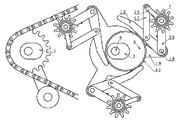
原理説明の為、図では部品の形状や部品相互間の距離を一部簡略化、誇張してあり、周知の技術については省略してある。図1において、出力軸2を支持する本体フレーム1と、駆動軸6とカム5を支持する本体フレーム1は連続した一体のフレームである。基本構成としては、本体フレーム1にチェーンテンショナー4を、揺動可能かつバネ等によって半時計方向にテンションを掛けて装着し、本体フレーム1に出力軸2を回転自在に装着し、出力軸2に出力歯車3を固着し、本体フレーム1の出力歯車3の右方向所要位置に、カム5を固着し、カム5の中心より左に偏心した位置に駆動軸6を回転自在に装着し、駆動軸6にアーム角度制御板21を相対回転制御可能に装着し、駆動軸6に回転板18を固着し、回転板18の中心から等距離かつ相互が等間隔な3箇所の位置に駆動軸6と平行にアーム軸19を設け、その各々にアーム20の一端を軸周りに回転可能に装着し、アーム20上の一点と対向するアーム角度制御板21上の点をアーム角度制御リンク22で連結し、アーム20の他端に駆動軸6と平行に遊星歯車軸9を設け、その各々に遊星歯車7を自転自在に装着し、遊星歯車ハブ8にワンウェイクラッチ10のインナーレース11を時計方向に回転自在な向きで固着し、ワンウェイクラッチ10のアウターレース12に梃子13の一端の作用点部分を固着し、梃子13上の一点とアーム20上の一点をカム追従バネ24で連結し、遊星歯車7と出力歯車3にチェーン14を掛け渡す。図1では省略してあるが、アーム角度制御板21と回転板18の間には図11に示すようなアーム角度制御機構を設け、遊星歯車軸9には図9に示すような爪掛けはずしガイド31を設ける。For the purpose of explaining the principle, in the drawing, the shape of parts and the distance between parts are partially simplified and exaggerated, and well-known techniques are omitted. In FIG. 1, the
以下、図1により、その作用を説明する。上記構成において、駆動軸6に時計方向に駆動力を掛けると、遊星歯車7が駆動軸6、回転板18と伴にその周囲を公転して、噛合っているチェーン14を引いて出力歯車3を回転させ、駆動力を伝達する。ここで、通常は回転板18と一体回転しているアーム角度制御板21を、回転板18に対して相対回転させると、アーム角度制御リンク22により、アーム20がアーム軸19の軸周りに回転し、駆動軸6と遊星歯車7の距離つまり遊星歯車7の公転半径が変化して、無段階に変速しながら駆動力を伝達する。梃子13は遊星歯車7に随って駆動軸6の周囲を公転するが、カム5が駆動軸6より右方向に偏心している為、右側の梃子13は、カム5に接近して、時計方向に回転し、ワンウェイクラッチ10を介して遊星歯車7を時計方向に自転させ、その自転と駆動軸6を中心とした公転の合成速度でチェーン14が引かれる。左側下と左側上の梃子13は、カム5から遠ざかり、反時計方向に回転して、ワンウェイクラッチ10のアウターレース12を反時計方向に回転させる。その結果、左側下の遊星歯車7にはトルクが掛からず、チェーン14からスムーズに外れ、左側上の遊星歯車7は、チェーン14に接近して、相対的に速度の速いチェーン14に歯を押されて自由回転しながらピッチが合う位置で噛合う。以上の動作で連続回転し、無段階に変速し、駆動力を伝達する。The operation will be described below with reference to FIG. In the above configuration, when a driving force is applied to the driving
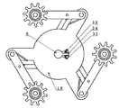
以下、他の図について説明する。図3は、アーム角度制御板21とアーム角度制御リンク22とアーム20の位置関係を示している、相対回転させる機構は周知の為、省略してあるが、図11はその機構の一例である、アーム角度制御板21と回転板18にはそれぞれクラウンギア36,37が固着されており、中間には両クラウンギア38が回転自在に支持されており、アーム角度制御板クラウンギア36は両クラウンギア38に、位置が固定されて回転自在に支持された固定ピニオンギア39で連係されており、回転板クラウンギア37は、移動可能で回転自在に支持された移動ピニオンギア40で両クラウンギア38に連係されている。この状態で移動ピニオンギア40を駆動軸6周りに移動すれば、回転板18とアーム角度制御板21は相対回転する。図4は、カム5をクランク15に置き換え、梃子13の一端とクランク軸41をクランク15で連結した場合の正面図である、実際に自転車に応用する場合は駆動軸6が手前方向に貫通する為、クランク軸41は駆動軸6を内に取り込む直径となる。図5、6はクランク15とカム5のそれぞれの方式で、遊星歯車7と梃子13の間に第一、第二梃子連動リンク16、17を介在させる、つまり梃子13に発生した回転をパンタグラフで伝達及び増幅する機構であり、部品点数は増えるが、梃子13とカム5の摺動や、クランク15の長さに制限されず公転半径の変化を大きくできることを示している。図7は公転半径の変化をスライダー25で実現する方法であり、スライド方向が駆動軸6からの放射方向に対しやや傾斜していることで、駆動負荷がスライド方向への力となってスライダーバネ26の反発力と均衡している。図8はアーム20への追加機構の例で、上はチェーンガイド円板32を取付けた場合の、手前の円板を省略してある部分図であり、下はアブソーバ27で急激な動きを抑制するもの、右はアーム20の位置がストッパー28に連動して次のアーム20の動きを制限する機構の例をそれぞれ示している。尚、図4以降は、アーム角度制御板21を使用せず、アーム20にアーム角度制御バネ23を配して、その角度が駆動軸6の負荷に比例して自動的に変動する機構としているが、図面の簡略化が目的で、機能相互に必然性は無い。但し、アーム角度制御板21を使用する場合でもこのアーム角度制御バネ23は駆動力によるアーム20の回転力を打ち消して、アーム角度制御板21の回転を助ける働きがある。尚、チェーン14は一部省略してある。図9は、爪掛けはずしガイド31が遊星歯車軸9に固着されており、遊星歯車7は、駆動軸6の左上の位置でチェーン14に再度噛合ったところである、この位置では、梃子13とそれに固着されたアウターレース12が半時計方向に大きく回転しており、ワンウェイクラッチ10の爪30が、爪掛けはずしガイド31に乗り上げ、インナーレース11の爪車44から強制的に外されて、インナーレース11に固着された遊星歯車7を両方向回転自在にしている、その為、この位置では遊星歯車7とチェーン14の相対速度差に関わらず遊星歯車7はチェーン14に追従して噛合う。その後、駆動軸6の上方向から右方向への遊星歯車7の公転に伴って梃子13が時計方向に回転し、爪30は爪掛けはずしガイド31から外れてインナーレース11の爪車44に接触し、元の機能に復帰する。爪掛けはずしガイド31は以上の機能であれば、他の形態でも良い。図10は、駆動軸6と回転板18を固着せず、キー溝35の中で、キー34と回転板18の間に緩衝材33を介在させた場合の原理図である。図12は遊星歯車軸9を駆動軸6に対してやや角度を持たせることで、遊星歯車間の距離をより詰めることができることを示している、図では省略してあるが、歯面は、はすば歯車状となっており、チェーン14のピンとは疑似平行に噛合う。又、チェーン14のピンを円筒形でなく、紡錘形にすることでも噛合いがスムーズになる。図13は、梃子の回転軸と遊星歯車軸を同軸にしない方法で、かつ、梃子と遊星歯車軸を一体化した例である。図14は対向する円錐車45の間隙を変速梃子46で調整することで遊星歯車7の公転半径を制御する機構の例である。Other figures will be described below. FIG. 3 shows the positional relationship among the arm
1 本体フレーム
2 出力軸
3 出力歯車
4 チェーンテンショナー
5 カム
6 駆動軸
7 遊星歯車
8 遊星歯車ハブ
9 遊星歯車軸
10 ワンウェイクラッチ
11 インナーレース
12 アウターレース
13 梃子
14 チェーン
15 クランク
16 第一梃子連動リンク
17 第二梃子連動リンク
18 回転板
19 アーム軸
20 アーム
21 アーム角度制御板
22 アーム角度制御リンク
23 アーム角度制御バネ
24 カム追従バネ
25 スライダー
26 スライダーバネ
27 アブソーバ
28 ストッパー
29 ころ
30 爪
31 爪掛けはずしガイド
32 チェーンガイド円板
33 緩衝材
34 キー
35 キー溝
36 アーム角度制御板クラウンギア
37 回転板クラウンギア
38 両クラウンギア
39 固定ピニオンギア
40 移動ピニオンギア
41 クランク軸
42 回転リング
43 梃子作用点軸
44 爪車
45 円錐車
46 変速梃子DESCRIPTION OF
Claims (8)
Priority Applications (1)
| Application Number | Priority Date | Filing Date | Title |
|---|---|---|---|
| JP2009072767A JP2010203602A (en) | 2009-03-01 | 2009-03-01 | Continuously variable transmission using one-way planetary gear |
Applications Claiming Priority (1)
| Application Number | Priority Date | Filing Date | Title |
|---|---|---|---|
| JP2009072767A JP2010203602A (en) | 2009-03-01 | 2009-03-01 | Continuously variable transmission using one-way planetary gear |
Publications (1)
| Publication Number | Publication Date |
|---|---|
| JP2010203602A true JP2010203602A (en) | 2010-09-16 |
Family
ID=42965275
Family Applications (1)
| Application Number | Title | Priority Date | Filing Date |
|---|---|---|---|
| JP2009072767A Pending JP2010203602A (en) | 2009-03-01 | 2009-03-01 | Continuously variable transmission using one-way planetary gear |
Country Status (1)
| Country | Link |
|---|---|
| JP (1) | JP2010203602A (en) |
Cited By (3)
| Publication number | Priority date | Publication date | Assignee | Title |
|---|---|---|---|---|
| CN103527735A (en) * | 2013-11-04 | 2014-01-22 | 苏州建莱机械工程技术有限公司 | Planet intermittent synchronizing mechanism |
| CN106609824A (en) * | 2015-10-26 | 2017-05-03 | 刘运武 | Lever-type energy-saving variable-speed motor |
| JP2017516709A (en) * | 2015-04-01 | 2017-06-22 | スーンビ カンパニー リミテッド | Drone-type life-saving equipment dropping device |
-
2009
- 2009-03-01 JP JP2009072767A patent/JP2010203602A/en active Pending
Cited By (3)
| Publication number | Priority date | Publication date | Assignee | Title |
|---|---|---|---|---|
| CN103527735A (en) * | 2013-11-04 | 2014-01-22 | 苏州建莱机械工程技术有限公司 | Planet intermittent synchronizing mechanism |
| JP2017516709A (en) * | 2015-04-01 | 2017-06-22 | スーンビ カンパニー リミテッド | Drone-type life-saving equipment dropping device |
| CN106609824A (en) * | 2015-10-26 | 2017-05-03 | 刘运武 | Lever-type energy-saving variable-speed motor |
Similar Documents
| Publication | Publication Date | Title |
|---|---|---|
| KR102433297B1 (en) | Continuously variable transmission | |
| JP4582607B2 (en) | Electrical machine | |
| ES2793488T3 (en) | Shift device and drive unit | |
| EP3650329B1 (en) | Hub gear | |
| EP2586694A1 (en) | Electrically assisted bicycle | |
| TW200302796A (en) | Transmission for vehicle | |
| CZ303289B6 (en) | Bicycle internal transmission device and method of power transmission in such a device | |
| JP2010203602A (en) | Continuously variable transmission using one-way planetary gear | |
| WO2014201938A1 (en) | Flexibly engaged continuously variable transmission gearbox | |
| WO2006107152A1 (en) | Speed change hub for bicycle | |
| US10605321B2 (en) | Transmission with a torsion spring and method for operating a transmission | |
| KR102147025B1 (en) | Nonstep variable speed gear for bike | |
| US10167055B2 (en) | Variably expanding chain transmission | |
| WO2006135213A1 (en) | Speed change hub for bicycle | |
| CN108138926A (en) | Three fast motorcycle gear boxes | |
| US20170349237A1 (en) | An automatic transmission system where gear engagement is determined by the angular velocity of the driven wheel | |
| CN203439221U (en) | Front chain wheel disc mechanism of automatic speed-changing bicycle | |
| KR101889307B1 (en) | continuously variable transmission | |
| EP2205892B1 (en) | Transmission | |
| WO2014120031A1 (en) | Variable ratio transmission element and system comprising the variable ratio transmission element | |
| US20050096162A1 (en) | Continuously variable transmission, and a transfer case including a continuously variable transmission | |
| WO1996001205A1 (en) | An infinitely variable transmission for a bicycle | |
| KR20110112146A (en) | Automatic multi-speed changing system for a bicycle | |
| KR20140109188A (en) | Bicycles transmission | |
| WO2018178898A1 (en) | Automatic transmission for bicycles |