JP2010201733A - Drill bit - Google Patents
Drill bit Download PDFInfo
- Publication number
- JP2010201733A JP2010201733A JP2009048596A JP2009048596A JP2010201733A JP 2010201733 A JP2010201733 A JP 2010201733A JP 2009048596 A JP2009048596 A JP 2009048596A JP 2009048596 A JP2009048596 A JP 2009048596A JP 2010201733 A JP2010201733 A JP 2010201733A
- Authority
- JP
- Japan
- Prior art keywords
- bit
- tip
- dust suction
- drill bit
- dust
- Prior art date
- Legal status (The legal status is an assumption and is not a legal conclusion. Google has not performed a legal analysis and makes no representation as to the accuracy of the status listed.)
- Pending
Links
Images


Abstract
Description
本発明は、コンクリートや石材等に穿孔作業をおこなうドリルビットに関し、さらに詳しくはアンカーボルト穴の穿孔に好適なドリルビットに関する。 The present invention relates to a drill bit for drilling a concrete or stone material, and more particularly to a drill bit suitable for drilling an anchor bolt hole.
従来より、コンクリートや石材等に対して穿孔作業をおこなう場合、穿孔工具として、ドリルビットが使用される。 Conventionally, when drilling a concrete or stone material, a drill bit is used as a drilling tool.
そして、かかるドリルビットは、コンクリート面への所謂「アンカーボルト穴」の穿孔に使用される場合がある。
かかる「アンカーボルト穴」は、その穴内に植設される金属製のアンカーボルトに所定の強固な耐引き抜き力を得るため、穴内に存在する切削屑等を可及的に除去しておく必要がある。
このため、前記「アンカーボルト穴」の穿孔作業の後に、集塵機等を使用して、穴内の切削屑等を取り除く、所謂「塵芥除去作業」が必要となる。つまり、アンカーボルトを前記アンカーボルト穴に植設する前に、該穴内に付着等する前記切削屑を可及的に取り除いておくことが求められる。
Such drill bits may be used for drilling so-called “anchor bolt holes” in concrete surfaces.
Such an “anchor bolt hole” needs to remove as much as possible cutting chips and the like existing in the hole in order to obtain a predetermined strong pull-out force to the metal anchor bolt implanted in the hole. is there.
For this reason, a so-called “dust removal operation” is required after the drilling operation of the “anchor bolt hole”, by using a dust collector or the like to remove the cutting waste in the hole. That is, before the anchor bolt is implanted in the anchor bolt hole, it is required to remove as much as possible the cutting waste adhering to the hole.
そこで、従来の場合には、ドリルビットで穿孔した後に、集塵機を使用して、基端が吸引機の吸引口に接続された清掃ノズルの先端をアンカーボルト穴に挿入して、該穴内の切削屑や他の塵芥等を吸引して除去していた。この種の集塵機として、例えば、本出願人が提供する集塵機がある(特許文献1)
また、穿孔作業の際に、先端で発生する切粉等を穿孔作業と同時に回収するために、ドリルビット先端の中心に吸塵穴を形成したドリルビットが使用される場合がある。かかる吸塵穴を備えたドリルビットは、ドリルビット先端の切刃部が2箇所、つまり切刃部が180度の間隔をおいて配置されたものであった。つまり、かかるドリルビットは、ビットシャフト部の中央に、切刃部の幅より径の大きい吸塵穴を設け、かかる吸塵穴の先端の開口の一部を、前記切刃部と切刃部の間の部分から先端方に臨ませた形態を有するものであった(特許文献2)。
Therefore, in the conventional case, after drilling with a drill bit, the tip of the cleaning nozzle whose base end is connected to the suction port of the suction device is inserted into the anchor bolt hole using a dust collector, and the cutting in the hole is performed. Scraps and other dust were removed by suction. As this type of dust collector, for example, there is a dust collector provided by the present applicant (Patent Document 1).
In addition, in order to collect chips and the like generated at the tip during the drilling operation at the same time as the drilling operation, a drill bit in which a dust suction hole is formed at the center of the drill bit tip may be used. The drill bit provided with such a dust suction hole has two cutting blade portions at the tip of the drill bit, that is, the cutting blade portions are arranged at an interval of 180 degrees. That is, in such a drill bit, a dust suction hole having a diameter larger than the width of the cutting blade portion is provided in the center of the bit shaft portion, and a part of the opening at the tip of the dust suction hole is provided between the cutting blade portion and the cutting blade portion. It had the form which faced the tip side from the part (patent document 2).
しかしながら、切刃部を3箇所以上設けた形態のドリルビットの場合に、前記構成を採用することはできない。つまり、各切刃部と切刃部の間から吸塵穴の先端の開口が部分的にせよ先端方に露呈させるほど大きな径の当該吸塵穴をビットシャフト部に形成すると、該ビットシャフト部の径方向の肉厚が薄くなって、剛性が低下する懸念がある。特に、かかるドリルビットの場合には、軸方向に適宜間隔で衝撃力を付与しながら回転させて穿孔をおこなうため、前記肉厚が薄くなると、強度的に問題が生じる。
また、切刃部を先端に具備するビット先端部の基端に、ビットシャフト部を一体に溶着した形態のドリルビットの場合には、前記吸塵穴の径を前述の如く単純に一義的に大きくすると、ビット先端部とビットシャフト部との間の接合面積(溶着面積)が小さくなって、接合強度が不足し、長期間の使用に耐え得ないものとなる懸念がある。
However, in the case of a drill bit having three or more cutting edge portions, the above configuration cannot be adopted. In other words, if the dust suction hole having a diameter large enough to expose the tip end of the dust suction hole partially or between the cutting blade part to the tip side is formed in the bit shaft part, the diameter of the bit shaft part There is a concern that the thickness in the direction becomes thin and the rigidity decreases. In particular, in the case of such a drill bit, since the drilling is performed by rotating while applying an impact force at an appropriate interval in the axial direction, a problem arises in strength when the thickness is reduced.
Further, in the case of a drill bit in which the bit shaft portion is integrally welded to the base end of the bit tip portion having the cutting edge portion at the tip, the diameter of the dust suction hole is simply and uniquely increased as described above. Then, there is a concern that the bonding area (welding area) between the bit tip portion and the bit shaft portion becomes small, the bonding strength is insufficient, and the long-term use cannot be endured.
一方、前記問題点を解決すべく、前記吸塵穴の径を小径にすると、該吸塵穴の先端への露呈開口面積が不足し、吸塵効果が低いものとなってしまう。 On the other hand, if the diameter of the dust suction hole is made small in order to solve the above problems, the exposed opening area to the tip of the dust suction hole is insufficient, and the dust suction effect is low.
本発明は、このような状況に鑑みておこなわれたもので、前記相矛盾する技術的課題を解決したドリルビットを提供することを目的とする。 The present invention has been made in view of such circumstances, and an object of the present invention is to provide a drill bit that solves the technical problems that contradict each other.
本発明にかかるドリルビットは、先端に少なくとも3つ以上の切刃部が周方向に離間して配置され、これら各切刃部に形成されるすくい面と逃げ面の接合稜線を切刃となす形態のビット先端部と、このビット先端部の基端面に、一体に回転するよう先端面が溶着されたビットシャフト部とを有するドリルビットにおいて、
前記ビットシャフト部にその長手方向に延びる吸塵通路を備えるとともに、
前記ビット先端部の、底面視において前記すくい面とその回転方向前方に位置する切刃部の逃げ面とが接合する各境界の外径方に先端が開口し、基端が前記吸塵通路に連通するべく、前記長手方向に対して交角を有するように、それぞれ形成された吸塵補助通路を、該ビットシャフト部の前記吸塵通路の吸込み上流方に備えていることを特徴とする。
In the drill bit according to the present invention, at least three or more cutting blade portions are spaced apart from each other in the circumferential direction at the tip, and the joining ridge line between the rake face and the flank surface formed on each cutting blade portion serves as the cutting edge. In a drill bit having a bit tip portion of the form and a bit shaft portion having a tip surface welded so as to rotate integrally with the base end surface of the bit tip portion,
The bit shaft portion is provided with a dust suction passage extending in the longitudinal direction thereof,
The tip end of the bit has an opening on the outer diameter side of each boundary where the rake face and the flank face of the cutting edge located forward in the rotational direction in bottom view are joined, and the base end communicates with the dust suction passage. Therefore, the dust suction auxiliary passages formed so as to have an intersection angle with respect to the longitudinal direction are provided upstream of the suction of the dust suction passages of the bit shaft portion.
しかして、このように構成され本発明にかかるドリルビットによれば、前記切刃部で穿設されて切削屑となった粉塵は、各切刃部のすくい面とその回転方向前方に位置する切刃部の逃げ面の間にそれぞれ形成された前記吸塵補助通路の各先端の開口から当該吸塵補助通路を通って、前記吸塵通路に吸引されることになる。特に、各切刃部のすくい面の回転方向前方に前記吸塵補助通路の前記開口が存在するため、すくい面ですくい取られ飛散した状態となっている塵芥等を効果的に吸引することができる。
このため、切削によって発生したコンクリート等の粉塵は、該ドリルビットによって穿孔された穿設穴から外部に拡散することなく吸塵通路に効率的に吸塵される。従って、前記吸塵通路の基端側をホース等を介して集塵機の吸引口に接続しておけば、穿孔後の穿設穴内には粉塵等は殆ど存在せず、従って、穿孔終了後にそのままの状態でアンカーボルトを植設することが可能となる。
Thus, according to the drill bit configured as described above, the dust that has been drilled by the cutting edge portion to become cutting waste is located on the rake face of each cutting edge portion and in the front in the rotation direction thereof. From the opening at each end of the dust suction auxiliary passage formed between the flank faces of the cutting edge portion, the dust suction passage is sucked into the dust suction passage. In particular, since the opening of the dust suction auxiliary passage exists in front of the rake face of each cutting edge portion in the rotational direction, it is possible to effectively suck dust that has been scooped and scattered by the rake face. .
For this reason, dust such as concrete generated by cutting is efficiently sucked into the dust suction passage without diffusing outside from the drilled hole drilled by the drill bit. Therefore, if the base end side of the dust suction passage is connected to the suction port of the dust collector via a hose or the like, there will be almost no dust in the drilled hole after drilling, and therefore the state as it is after drilling is completed. It becomes possible to plant anchor bolts.
また、前述のように、前記吸塵補助通路の先端が底面視において前記すくい面とその回転方向前方に位置する切刃部の逃げ面とが接合する各境界の外径方に開口するように設けられているため、前記ビット先端部とビットシャフト部とは、該ビット先端部の基端面と該ビットシャフト部の先端面とが比較的大きな面積で接触させることが可能となる。このため、前記ビット先端部とビットシャフト部とは、これらの溶着面を大きくとることができ、この結果、強固に溶着することが可能となる。 Further, as described above, the tip of the dust suction auxiliary passage is provided so as to open to the outer diameter side of each boundary where the rake face and the flank face of the cutting edge portion positioned forward in the rotation direction join in the bottom view. Therefore, the base end surface of the bit front end portion and the front end surface of the bit shaft portion can be brought into contact with each other with a relatively large area. For this reason, the said bit front-end | tip part and a bit shaft part can take these welding surfaces large, As a result, it becomes possible to weld firmly.
また、前記ドリルビットにおいて、前記吸塵通路を前記ビットシャフト部の先端面に、任意の適宜面積を有して貫通させた構成とすると、製造工程において該吸塵通路の加工が容易におこなえると共に、前記ビット先端部との接触面積が適度に減じられた構成を得ることができ、かかる場合に、接続すべき二つの部材の接触部分で発生する電気抵抗で生じる熱によって溶着させる形態の接合手法を採用する場合には、ビット先端部とビットシャフト部との接触面積を適度に小さくすることができるため、電気溶着時に両者を接合・挟着させる絶対圧力値を低くでき、従って、小さな能力の溶着設備でもって溶着を実施することが可能となる。しかも、前記ビット先端部とビットシャフト部との間に作用する回転トルクは、これらの外径領域に位置する溶着部分で受けることになるため、前述のように両者の接触面積が比較的小さくとも、接合部分に必要な回転トルク伝達性能を得ることができる。 Further, in the drill bit, when the dust suction passage is configured to penetrate the tip end surface of the bit shaft portion with any appropriate area, the dust suction passage can be easily processed in the manufacturing process, and It is possible to obtain a configuration in which the contact area with the bit tip is moderately reduced. In such a case, a bonding method is adopted in which welding is performed by heat generated by electrical resistance generated at the contact portion of the two members to be connected. In this case, the contact area between the bit tip and the bit shaft can be appropriately reduced, so that the absolute pressure value for joining and clamping the two during electric welding can be lowered, and therefore the welding equipment with small capacity Thus, welding can be performed. Moreover, since the rotational torque acting between the bit tip portion and the bit shaft portion is received by the welded portion located in these outer diameter regions, as described above, even if the contact area between them is relatively small. The rotational torque transmission performance required for the joint portion can be obtained.
また、前記ドリルビットにおいて、前記ビット先端部の基端面と、前記ビットシャフト部の先端面とを、共にフラットな面で構成すると、該ビット先端部とビットシャフト部とを、共に、シンプルな構造にすることができ、製造時の加工が容易となる。 Further, in the drill bit, when the base end surface of the bit tip portion and the tip surface of the bit shaft portion are both configured as flat surfaces, the bit tip portion and the bit shaft portion are both simple structures. It becomes easy to process at the time of manufacture.
また、前記ドリルビットにおいて、前記ビット先端部の基端面に凹凸を形成するとともに、前記ビットシャフト部の先端面に前記凹凸を補完するような形態の凹凸を形成した構成とすると、該ビット先端部とビットシャフト部との接触面積が増加するとともに、該凹凸同士の係合により、穿孔加工時にドリルビットに作用する回転方向の応力(回転トルク)を効果的に受容することができる。このため、大きな回転トルクに対しても耐えうる構造となる。 Further, in the drill bit, when the concave and convex portions are formed on the base end surface of the bit distal end portion and the concave and convex portions are formed on the distal end surface of the bit shaft portion, the bit distal end portion is formed. The contact area between the bit shaft portion and the bit shaft portion is increased, and the engagement of the projections and depressions allows the stress in the rotating direction (rotational torque) acting on the drill bit during drilling to be effectively received. For this reason, it becomes a structure which can endure a big rotational torque.
前述のように構成された本発明によると、先端に3つ以上の切刃部を備えたドリルビットにおいて、穿孔作業時に、ドリルビット先端部において高い吸塵性能を奏し、且つ、耐久性に優れた、しかも、高い回転トルクを伝達できるドリルビットとなる。 According to the present invention configured as described above, a drill bit having three or more cutting blades at the tip exhibits high dust absorption performance at the tip of the drill bit and has excellent durability during drilling operations. And it becomes a drill bit which can transmit high rotational torque.
[実施例]
以下、本発明の実施例を図面を参照しながらより具体的に説明する。
[Example]
Hereinafter, embodiments of the present invention will be described more specifically with reference to the drawings.
(実施例1)
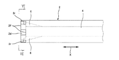
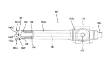
図2に示すように、本実施例にかかるドリルビット1は、大別して、ビットシャフト部2と、その先端方に一体に設けられるビット先端部3を具備している。
Example 1
As shown in FIG. 2, the
前記ビットシャフト部2は、基端部に電動ドリル装置10(図14参照)のチャック部分10c(図14参照)に取着される断面が正8角形状のシャンク部2Aと、その先端方に形成される断面が円形で外径が部位によって異なるシャフト主部2Bとを具備している。
そして、前記シャフト主部2Bは、先端部分から中央部位よりやや基端方まで延びる同一径からなるシャフト先端部2aと、その基端方に隣接し前記シャフト先端部2aよりやや太径の回転支持部2bと、さらにその基端方に隣接し前記シャンク部2Bに基端が一体に連結された部位によって径が変化する延設部2cとを有する。
前記シャンク先端部2aは、円形状の横断面の中心に、図4に図示するように、このドリルビット1の長手方向X(図2のX矢印方向参照)に延びる吸塵通路4を具備している。
図4に図示するように、この吸塵通路4の基端は、前記回転支持部2bに形成されている円形横断面を径方向に貫く吸塵接続通路5に接続されている。
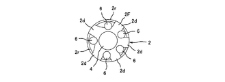
一方、前記吸塵通路4の先端は、図5,図6に示すように、このビットシャフト部2の先端面2Fまで延設されて、該先端面2Fに開口している。また、図6に図示するように、このビットシャフト部2の先端面2Fに開口している前記吸塵通路4の外径方には、該吸塵通路4に対して離間して周囲から取り囲むように、複数(この実施例では、切刃部の数に合わせて5つ)の吸塵補助通路6の先端の開口が形成されている。そして、この吸塵補助通路6は、図4あるいは図5に図示するように、前記長手方向Xに対して交角を有するように前記吸塵通路4に向かって延設され、これらの吸塵補助通路6の各基端は前記吸塵通路4に連接されている。
また、このビットシャフト部2の先端面2Fには、この実施例の場合、図5,図6に図示するように、外周縁部において先端方に突出した円筒状の外周壁部2rが形成されており、且つ、この外周壁部2rには、前記ビット先端部3に形成されている切刃部3c(図1,図3参照)と干渉する部位に、該干渉しないように、切り欠き2dが設けられて、全体の形状が概略クラウン状の形態に形成されている。
The
The shaft main portion 2B includes a shaft
The
As shown in FIG. 4, the base end of the
On the other hand, as shown in FIGS. 5 and 6, the tip of the
Further, in this embodiment, as shown in FIGS. 5 and 6, a cylindrical outer
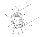
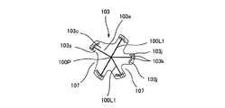
前記ビット先端部3は、図1,図3あるいは図7に図示するように、先端に少なくとも3つ以上の切刃部3cが周方向に形成されている。この実施例の場合には、5つの切刃部3cが周方向に外径部分が互いに離間して、底面視における概略の形態が「星形」に形成されている。また、図3あるいは図7に図示するように、各切刃部3c間の周方向における間隔は、5つのうちの、互いに隣接する3つの切刃部3cは90度の間隔をもって配置されており、また互いに隣接する4つの切刃部3c(図3において左半分に位置する切刃部3c)は、互いに60度の間隔をもって配置されている。
そして、各切刃部3cは、回転方向R(図3の矢印R参照)前方にすくい面3sと回転方向R後方に逃げ面3eを備えている。各切刃部3cのすくい面3sと逃げ面3eの接合稜線L1によって切刃が形成されている。
また、各切刃部3cの切刃の内径端は、このドリルビット1の回転中心O1で各接合して、尖頭状のチゼルポイントPを形成している。
そして、図7に図示するように、前記一つの切刃部3cの逃げ面3eとその回転方向後方に位置する切刃部3cのすくい面3sの間には、底面視において、略三角形状の隙間7が形成されている。従って、この実施例の場合には、5つの各切刃部3cの各間に、それぞれ1つの前記隙間7が形成されている。
図3に図示するように、前記隙間7が形成されている各位置に、つまり、各逃げ面3eとすくい面3sの境界の外径方には、前記ビットシャフト部2の吸塵補助通路6の先端が開口している。正確には、該吸塵補助通路6の全断面積のうちの殆どの部分(この実施例では略95%程度の部分)がこの隙間7に開口している。
As shown in FIG. 1, FIG. 3, or FIG. 7, the
Each
Further, the inner diameter end of the cutting edge of each
As shown in FIG. 7, the bottom face view has a substantially triangular shape between the
As shown in FIG. 3, at each position where the
また、前記ビット先端部4は前記ビットシャフト部2に対して、該ビット先端部4の各切刃部3cが該ビットシャフト部2の前記切り欠き2dに挿入されるように配置される。つまり、前記ビットシャフト部3の先端面3F(この実施例では先端面3Fのうちの外周壁部2r)に前記切り欠き2dによって凹凸が形成され、前記ビット先端部4の基端面(この実施例では切刃部3cの底面)に該切刃部3cと隙間7とによって凹凸が形成されているが、図1に明らかに示されるように、これらビット先端部4とビットシャフト部2の各凹凸が互いに補完するように、即ち噛合するような状態で、該ビット先端部4の基端面がビットシャフト部2の先端面に一体状に接合されている。
Further, the
そして、この実施例では、前記接合は、電気抵抗による発熱によって両者が溶着される形態の接続手法(溶着手法)によっておこなわれている。もちろん、電気抵抗による溶着に代えて、他の溶着手法、例えば、ろう付け溶接によって接合してもよく、あるいはレーザ光を用いた溶着等であってもよい。あるいは前記接合は接着剤によっておこなわれてもよい。 And in this Example, the said joining is performed by the connection method (welding method) of the form with which both are welded by the heat_generation | fever by electrical resistance. Of course, instead of welding by electric resistance, other welding methods such as brazing welding may be used, or welding using laser light may be used. Alternatively, the joining may be performed with an adhesive.
ところで、図1,図3に図示するように、前記切刃部3cの外径端部且つ先端部にすくい角および逃げ角がその内径方の部分に比べて鈍角になった補強切刃部3kが形成され、穿孔作業時の衝撃に対して外径端部が欠落することがないように構成し、耐久性が向上するように構成されている。そして、前記補強切刃面3kの周方向において隣接して、すくい角および逃げ角がより鋭角になった調整面部3jが形成されている。
By the way, as shown in FIGS. 1 and 3, the reinforcing
前述のように構成された本実施例にかかるドリルビット1によれば、図14に図示するように、前記シャンク部2Aを、回転と軸方向(長手方向に一致)の振動動作を付与することができる電気ドリル装置(振動型電動ドリル装置)10のチャック部分10cに取着されて、被穿孔物、例えば、コンクリートに穿孔する際に、以下のように作用する。つまり、
図14に図示するように、前記ドリルビット1の回転支持部2bに配置され回転しない支持ホルダー12の吸引口を、吸引装置13の吸引口13aにホース14を介して接続した状態で、該電気ドリル装置10のスイッチ10aを操作してONにする。この動作によって、前記電気ドリル装置10は、前記ドリルビット1に回転動作と軸方向の振動動作を付与し、該ドリルビット1は、被穿孔物に対して穿孔する。この穿孔によって、切り屑等の塵芥が穿孔されている穴内に発生するが、かかる塵芥は、前記吸塵補助通路6の先端の開口から効果的に吸塵される。特に、各切刃部3cのすくい面3sの回転方向R前方に前記吸塵補助通路6の先端の開口が存在するため、該すくい面3sですくい取られた塵芥等を効果的に前記開口から吸引することができる。また、前記塵芥等の吸引は、前記吸塵補助通路6の吸引作用によって実行される。そして、本発明にかかる実施例1の場合には、前記塵芥等の吸引に際して、前記先端面2Fの周囲が、円筒状の外周壁部2rで囲まれているため、吸引ダクトの役目を果たして、切刃部3cで切削された切削屑は、前記吸塵補助通路6の先端の開口から、効果的に吸い込まれることになる。
According to the
As shown in FIG. 14, the suction port of the
このため、図15に図示するように、穿孔作業によって穿設穴16内に発生したコンクリート等の塵芥(粉塵)は、穿設穴16から外部に拡散することなく、前記吸塵補助通路6から吸塵通路4、吸塵接続通路5、ホース14を経て吸引装置13へ、効率的に吸塵される。
For this reason, as shown in FIG. 15, dust (dust) such as concrete generated in the
従って、穿設後の穿設穴16内には粉塵等は存在せず、従って、穿孔終了後にそのままの状態でアンカーボルト(図示せず)を植設することが可能となる。
Accordingly, there is no dust or the like in the drilled
(実施例2)
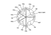
ところで、本発明にかかるドリルビットとしては、前記構成に代えて図8〜図13に図示するような構成のドリルビットであってもよい。つまり、
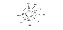
図8〜図13に図示するドリルビット101の場合には、ビットシャフト部102の先端面102Fが、図11,図12に図示するようにフラットな面で構成されており、かかる先端面102Fにビット先端部3の基端面がフラットに面接合するような状態で、接合されている。
その他の点では、前記実施例1と同じ構成を有するため、図1〜図7に示した実施例1の対応する構成に付された参照符号に100を加えた参照符号を、図8〜図13に示す実施例2にかかるドリルビットに付して、その詳細な説明を省略する。
(Example 2)
By the way, as a drill bit concerning this invention, it may replace with the said structure and the drill bit of a structure as illustrated in FIGS. 8-13 may be sufficient. That means
In the case of the
In other respects, since it has the same configuration as that of the first embodiment, the reference numeral added to the corresponding reference numeral of the first embodiment shown in FIGS. Detailed description of the drill bit according to the second embodiment shown in FIG.
そして、このように構成されたドリルビット101の場合には、基本的な作用としては、前述した実施例1の場合と同じであるが、前記ビットシャフト部102の先端部分の構成が平面で構成されているため、シンプルにすることができ、該ドリルビット101の製造がより容易となる点で優れている。
In the case of the
前記実施例1および実施例2にかかるドリルビット1,101の場合にも、前述のように、前記吸塵通路4,104あるいは前記吸塵補助通路6の前記先端面2F,102Fへの開口面積を調整することによって、つまり、開口面積をゼロに近い数値から所定の大きさ(具体的には該吸塵通路4,104あるいは吸塵補助通路6,106の基端方の面積)まで所定の面積に調整することによって、サイズの異なるドリルビットを製造する際に、前記電気抵抗による溶着に必要な単位面積当たりの押圧力に合致させることができる。換言すれば、電気抵抗による溶着装置の押圧能力が低い場合には、前記ビット先端部の基端面とビットシャフト部2の先端面の面積との接合面積を、該ビットシャフト部2の先端面の面積を小さくすることによって、単位面積当たり必要な押圧力を確保して、適正に溶着することが可能となる。
Also in the case of the
本発明は、前記実施例で説明した内容に限定されるものでなく、本発明の基本的な技術思想から逸脱することなく、種々変更して実施することが可能であることは言うまでもない。 It goes without saying that the present invention is not limited to the contents described in the above embodiments, and can be implemented with various modifications without departing from the basic technical idea of the present invention.
本発明にかかるドリルビットは、コンクリートや石材又はタイル等の穿孔対象物に対して穿孔する際等に使用することができる。 The drill bit according to the present invention can be used when drilling a drilling object such as concrete, stone, or tile.
1…ドリルビット
2…ビットシャフト部
2F…先端面
3…ビット先端部
3c…切刃部
3e…逃げ面
3s…すくい面
4…吸塵通路
6…吸塵補助通路
L1…接合稜線
X…長手方向
DESCRIPTION OF
Claims (4)
前記ビットシャフト部にその長手方向に延びる吸塵通路を備えるとともに、
前記ビット先端部の、底面視において前記すくい面とその回転方向前方に位置する切刃部の逃げ面とが接合する各境界の外径方に先端が開口し、基端が前記吸塵通路に連通するべく、前記長手方向に対して交角を有するように、それぞれ形成された吸塵補助通路を、該ビットシャフト部の前記吸塵通路の吸込み上流方に備えていることを特徴とするドリルビット。 At least three or more cutting blade portions are arranged at the tip end in the circumferential direction, and the bit tip portion is configured so that the joining edge line of the rake face and the flank face formed on each cutting edge portion serves as a cutting edge. In a drill bit having a bit shaft portion with a distal end surface welded so as to rotate integrally with a base end surface of the bit distal end portion,
The bit shaft portion is provided with a dust suction passage extending in the longitudinal direction thereof,
The tip end of the bit has an opening on the outer diameter side of each boundary where the rake face and the flank face of the cutting edge located forward in the rotational direction in bottom view are joined, and the base end communicates with the dust suction passage. Therefore, a drill bit characterized in that dust suction auxiliary passages formed so as to have an intersection angle with respect to the longitudinal direction are provided upstream of suction of the dust suction passage of the bit shaft portion.
Priority Applications (1)
| Application Number | Priority Date | Filing Date | Title |
|---|---|---|---|
| JP2009048596A JP2010201733A (en) | 2009-03-02 | 2009-03-02 | Drill bit |
Applications Claiming Priority (1)
| Application Number | Priority Date | Filing Date | Title |
|---|---|---|---|
| JP2009048596A JP2010201733A (en) | 2009-03-02 | 2009-03-02 | Drill bit |
Publications (1)
| Publication Number | Publication Date |
|---|---|
| JP2010201733A true JP2010201733A (en) | 2010-09-16 |
Family
ID=42963718
Family Applications (1)
| Application Number | Title | Priority Date | Filing Date |
|---|---|---|---|
| JP2009048596A Pending JP2010201733A (en) | 2009-03-02 | 2009-03-02 | Drill bit |
Country Status (1)
| Country | Link |
|---|---|
| JP (1) | JP2010201733A (en) |
Cited By (4)
| Publication number | Priority date | Publication date | Assignee | Title |
|---|---|---|---|---|
| WO2011145270A1 (en) * | 2010-05-21 | 2011-11-24 | 株式会社ミヤナガ | Drill bit |
| WO2014129119A1 (en) * | 2013-02-19 | 2014-08-28 | Fsテクニカル株式会社 | Diameter-expanding drill bit |
| WO2016129268A1 (en) * | 2015-02-13 | 2016-08-18 | 株式会社ミヤナガ | Dust suction drill and dust suction unit |
| JP2020525675A (en) * | 2017-06-27 | 2020-08-27 | ヒルティ アクチエンゲゼルシャフト | Drills for rock chiseling |
-
2009
- 2009-03-02 JP JP2009048596A patent/JP2010201733A/en active Pending
Cited By (12)
| Publication number | Priority date | Publication date | Assignee | Title |
|---|---|---|---|---|
| WO2011145270A1 (en) * | 2010-05-21 | 2011-11-24 | 株式会社ミヤナガ | Drill bit |
| JP5271450B2 (en) * | 2010-05-21 | 2013-08-21 | 株式会社ミヤナガ | Drill bit |
| US9162371B2 (en) | 2010-05-21 | 2015-10-20 | Kabushiki Kaisha Mayanaga | Drill bit |
| WO2014129119A1 (en) * | 2013-02-19 | 2014-08-28 | Fsテクニカル株式会社 | Diameter-expanding drill bit |
| EP2839941A4 (en) * | 2013-02-19 | 2016-01-27 | Fs Technical Corp | Diameter-expanding drill bit |
| JP6022670B2 (en) * | 2013-02-19 | 2016-11-09 | Fsテクニカル株式会社 | Drill bit for diameter expansion |
| US9573238B2 (en) | 2013-02-19 | 2017-02-21 | Fs Technical Corporation | Diameter expansion drill bit |
| WO2016129268A1 (en) * | 2015-02-13 | 2016-08-18 | 株式会社ミヤナガ | Dust suction drill and dust suction unit |
| JPWO2016129268A1 (en) * | 2015-02-13 | 2017-11-24 | 株式会社ミヤナガ | Dust-absorbing drill and dust-absorbing unit |
| US10335980B2 (en) | 2015-02-13 | 2019-07-02 | Kabushiki Kaisha Miyanaga | Dust suction drill and dust suction unit |
| JP2020525675A (en) * | 2017-06-27 | 2020-08-27 | ヒルティ アクチエンゲゼルシャフト | Drills for rock chiseling |
| US11691204B2 (en) | 2017-06-27 | 2023-07-04 | Hilti Aktlengesellschaft | Drill for chiseling stone |
Similar Documents
| Publication | Publication Date | Title |
|---|---|---|
| WO2016129268A1 (en) | Dust suction drill and dust suction unit | |
| JP5271450B2 (en) | Drill bit | |
| JP2010201733A (en) | Drill bit | |
| JP2006239826A (en) | Drill head | |
| JP2009255202A (en) | Drill head for cutting deep hole | |
| JP2015112732A (en) | Drill bit | |
| JP2007136643A (en) | Core drill | |
| KR20110128694A (en) | Drill bit | |
| JP2009178787A (en) | Drill, cutting insert for drill, and cutting method | |
| JP4856766B2 (en) | Core drill | |
| JP2005212487A (en) | Core drill | |
| JP2008062620A (en) | Drill bit | |
| WO2014162709A1 (en) | Rebar drill | |
| JP4233575B2 (en) | Core cutter | |
| JP2010214688A (en) | Core bit for drill | |
| JP3940716B2 (en) | Large-diameter woodworking cone | |
| JP6924214B2 (en) | Core drill bit | |
| JP5142911B2 (en) | Auxiliary attachment for chip discharge | |
| JP2006180866A (en) | Rotary cutter for bush cutter | |
| TWI598199B (en) | Vacuum type drilling device and its manufacturing method | |
| JPH05162010A (en) | Drill | |
| JP2010194679A (en) | Core drill | |
| KR200412093Y1 (en) | Drill for culture | |
| JP2522758Y2 (en) | Gun drill | |
| JPH09272007A (en) | Cutter for drilling and drilling tool with cutter for drilling |