JP2010197937A - Optical sheet, optical sheet laminated body, and back light device - Google Patents
Optical sheet, optical sheet laminated body, and back light device Download PDFInfo
- Publication number
- JP2010197937A JP2010197937A JP2009045532A JP2009045532A JP2010197937A JP 2010197937 A JP2010197937 A JP 2010197937A JP 2009045532 A JP2009045532 A JP 2009045532A JP 2009045532 A JP2009045532 A JP 2009045532A JP 2010197937 A JP2010197937 A JP 2010197937A
- Authority
- JP
- Japan
- Prior art keywords
- claw
- sheet
- optical sheet
- protruding
- protrusion
- Prior art date
- Legal status (The legal status is an assumption and is not a legal conclusion. Google has not performed a legal analysis and makes no representation as to the accuracy of the status listed.)
- Pending
Links
- 230000003287 optical effect Effects 0.000 title claims abstract description 51
- 210000000078 claw Anatomy 0.000 claims abstract description 121
- 230000002093 peripheral effect Effects 0.000 claims abstract description 7
- 238000009792 diffusion process Methods 0.000 description 23
- 239000004973 liquid crystal related substance Substances 0.000 description 20
- 230000005484 gravity Effects 0.000 description 6
- 229920003023 plastic Polymers 0.000 description 3
- 239000000088 plastic resin Substances 0.000 description 3
- 238000005401 electroluminescence Methods 0.000 description 2
- NIXOWILDQLNWCW-UHFFFAOYSA-N acrylic acid group Chemical group C(C=C)(=O)O NIXOWILDQLNWCW-UHFFFAOYSA-N 0.000 description 1
- 230000003247 decreasing effect Effects 0.000 description 1
- 238000010438 heat treatment Methods 0.000 description 1
- 238000003780 insertion Methods 0.000 description 1
- 230000037431 insertion Effects 0.000 description 1
- 238000004519 manufacturing process Methods 0.000 description 1
- 239000000463 material Substances 0.000 description 1
- 239000002184 metal Substances 0.000 description 1
- 238000000034 method Methods 0.000 description 1
- 239000002985 plastic film Substances 0.000 description 1
- 239000011347 resin Substances 0.000 description 1
- 229920005989 resin Polymers 0.000 description 1
Images


Landscapes
- Liquid Crystal (AREA)
- Planar Illumination Modules (AREA)
- Optical Elements Other Than Lenses (AREA)
- Securing Globes, Refractors, Reflectors Or The Like (AREA)
Abstract
【課題】光学シートおよびケースを大型化することなく、光学シートをケースから外れにくくする。
【解決手段】シート本体410と、シート本体の周縁41a内側から外側に向かう外方向に、シート本体の周縁から突出した突出部411aと、シート本体の周縁に沿う方向に突出部から突出した爪411bと、を備えており、突出部411aの突端から爪411bの突端まで成す辺が、突出部411aの突端から爪411bの突端に向かってシート本体410の周縁に漸近するよう傾斜している。
【選択図】図4An optical sheet and a case are prevented from being detached from the case without increasing the size of the optical sheet and the case.
SOLUTION: A sheet main body 410, a protrusion 411a protruding from the periphery of the sheet main body in an outward direction from the inside to the outside of the sheet main body 41a, and a claw 411b protruding from the protrusion in a direction along the periphery of the sheet main body. The side formed from the protruding end of the protruding portion 411a to the protruding end of the claw 411b is inclined so as to approach the peripheral edge of the sheet main body 410 from the protruding end of the protruding portion 411a toward the protruding end of the claw 411b.
[Selection] Figure 4
Description
本発明は、液晶表示装置等に用いられる光学シート、光学シート積層体及びバックライト装置に関する。 The present invention relates to an optical sheet, an optical sheet laminate, and a backlight device used for a liquid crystal display device and the like.
従来の液晶表示装置等の電子機器においては、フレキシブル配線基板等のシート部材を、ケースに設けたフックによってケースに固定していた。具体的には、背面ケースの上面に垂直に立設する支柱部と、支柱部の上端から水平方向に突出する鉤部とからなるフックをケースに設けると共に、シート部材に支柱部の断面とほぼ等しい形状の係止孔を形成し、係止孔にフックを通して引っ掛けることで、シート部材がケースから外れないようにしていた(特許文献1参照)。 In a conventional electronic device such as a liquid crystal display device, a sheet member such as a flexible wiring board is fixed to the case by a hook provided on the case. Specifically, the case is provided with a hook made up of a support column that stands vertically on the upper surface of the back case and a flange that protrudes in the horizontal direction from the upper end of the support column. An equal-shaped locking hole is formed and hooked through the locking hole so that the sheet member does not come off the case (see Patent Document 1).
ところで、バックライトを構成する光学シートは、周縁部のごく一部を除いてほぼ全面が表示領域となっている。このような光学シートに係止孔を設けようとすれば、係止孔を形成するためのスペースを表示領域の外側に大きく設ける必要があり、光学シートが大型化してしまう。
そこで、本発明が解決しようとする課題は、光学シートを大型化することなく、光学シートをケースから外れにくくすることである。
By the way, almost the entire surface of the optical sheet constituting the backlight is a display area except for a small part of the peripheral edge. If it is going to provide a locking hole in such an optical sheet, it will be necessary to provide the space for forming a locking hole largely outside a display area, and an optical sheet will enlarge.
Therefore, the problem to be solved by the present invention is to make it difficult to remove the optical sheet from the case without increasing the size of the optical sheet.
以上の課題を解決するため、本発明の一の態様によれば、
シート本体と、前記シート本体の周縁内側から外側に向かう外方向に、前記シート本体の周縁から突出した突出部と、前記シート本体の周縁に沿う方向に前記突出部から突出した爪と、を備えていることを特徴とする光学シートが提供される。
In order to solve the above problems, according to one aspect of the present invention,
A sheet body, a protrusion projecting from the periphery of the sheet body in an outward direction from the inner periphery to the outside of the sheet body, and a claw projecting from the protrusion in a direction along the periphery of the sheet body. An optical sheet is provided.
好ましくは、前記突出部の突端から前記爪の突端まで成す辺が、前記突出部の突端から前記爪の突端に向かって前記シート本体の周縁に漸近するよう傾斜する。
好ましくは、前記シート本体の形状は四角形であり、前記突出部は第1の爪が形成された第1の突出部及び第2の爪が形成された第2の突出部を備え、前記第1の突出部は前記シート本体の何れか一辺に設けられ、前記第2の突出部はその辺の対辺に設けられる。
好ましくは、前記シート本体の形状は正方形又は長方形であり、前記第1の突出部及び前記第2の突出部は、前記シート本体の中心に関してほぼ点対称となる位置に配置される。
好ましくは、光学シートと、更に他の光学シートが積層されていることを特徴とする光学シート積層体が提供される。
好ましくは、光学シート積層体において、前記他の光学シートは爪を持たず、前記突出部から突出した前記爪を備えた前記光学シートは前記他の光学シートの上面に積層される。
Preferably, a side formed from the protruding end of the protruding portion to the protruding end of the claw is inclined so as to approach the peripheral edge of the sheet main body from the protruding end of the protruding portion toward the protruding end of the claw.
Preferably, the shape of the sheet body is a quadrangle, and the protrusion includes a first protrusion formed with a first claw and a second protrusion formed with a second claw, The protruding portion is provided on one side of the sheet body, and the second protruding portion is provided on the opposite side of the side.
Preferably, the shape of the sheet main body is a square or a rectangle, and the first protrusion and the second protrusion are arranged at positions that are substantially point-symmetric with respect to the center of the sheet main body.
Preferably, an optical sheet laminate is provided in which an optical sheet and another optical sheet are laminated.
Preferably, in the optical sheet laminate, the other optical sheet does not have a claw, and the optical sheet including the claw protruding from the protruding portion is stacked on an upper surface of the other optical sheet.
本発明の他の態様によれば、
面発光装置と、前記面発光装置の上に載せられたシート本体と、前記シート本体の周縁内側から外側に向かう外方向に、前記シート本体の周縁から突出した突出部と、前記シート本体の周縁に沿う方向に前記突出部から突出した爪と、前記突出部及び前記爪が挿入される孔が形成され、前記孔に前記突出部及び前記爪が挿入されることによって前記シート本体を支持する支持部を備えることを特徴とするバックライト装置が提供される。
According to another aspect of the invention,
A surface light emitting device; a sheet main body placed on the surface light emitting device; a protrusion projecting from the peripheral edge of the sheet main body in an outward direction from the inner periphery to the outer periphery of the sheet main body; A nail projecting from the projecting portion in a direction along the direction, a hole into which the projecting portion and the nail are inserted, and a support for supporting the sheet body by inserting the projecting portion and the nail into the hole There is provided a backlight device comprising a unit.
本発明によれば、シート本体から突出させた突出部及び爪によって、光学シートを支持するので、光学シートの表示領域以外のスペースを最小限に抑えることができる。また、突出部及び爪を支持部に空けた孔に通し、爪を支持部の外側に引っ掛けることにより、光学シートをはずれにくくすることができる。 According to the present invention, since the optical sheet is supported by the projecting portion and the claw that are projected from the sheet main body, the space other than the display area of the optical sheet can be minimized. Further, the optical sheet can be made difficult to come off by passing the protruding portion and the claw through the hole formed in the support portion and hooking the claw on the outside of the support portion.
以下に、本発明を実施するための好ましい形態について図面を用いて説明する。但し、以下に述べる実施形態には、本発明を実施するために技術的に好ましい種々の限定が付されているが、発明の範囲を以下の実施形態及び図示例に限定するものではない。 Hereinafter, preferred embodiments for carrying out the present invention will be described with reference to the drawings. However, although various technically preferable limitations for implementing the present invention are given to the embodiments described below, the scope of the invention is not limited to the following embodiments and illustrated examples.
<第1の実施の形態>
まず、液晶表示装置1の構成について説明する。
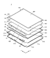
図1は、液晶表示装置1の分解斜視図である。この液晶表示装置1は、表示部ユニット2、上ケース23、下ケース24及びバックライト装置3を備える。
表示部ユニット2は、長方形又は正方形の板状をした液晶ディスプレイパネル21と、液晶ディスプレイパネル21の矩形状表示領域の周囲部から延びる帯状のFPC(Flexible Printed Circuit)22と、を有する。液晶ディスプレイパネル21は、液晶ディスプレイパネル21の表示領域とほぼ同形状の開口23aが形成された上ケース23と、同じく表示領域とほぼ同形状の開口24aが形成された下ケース24とによって挟まれている。液晶ディスプレイパネル21の表示領域が開口23a及び開口24aから露出している。FPC22の突端部は図示しない制御装置に接続されている。また、液晶ディスプレイパネル21の背面には、バックライト装置3が取り付けられ、バックライト装置3を発光させると、その光が液晶ディスプレイパネル21の表示領域を透過して画像が映し出されるようになっている。
<First Embodiment>
First, the configuration of the liquid
FIG. 1 is an exploded perspective view of the liquid
The
図2は、バックライト装置3の分解斜視図である。このバックライト装置3は、液晶ディスプレイパネル21の表示領域に光を照射するものである。バックライト装置3は、下から順に、ベース板31、反射シート32、LEDユニット33、導光板34、遮光テープ35、光学シート41〜43を備えている。
FIG. 2 is an exploded perspective view of the
ベース板31は、バックライト装置3の底部となる長方形又は正方形をした金属製の板状部材である。ベース板31の周囲には、支持部となる支持壁31aがベース板31の4辺に沿って立てた状態でそれぞれ設けられている。そして、ベース板31のある一辺に設けられた支持壁31aには孔311(図3に図示)及び313が形成されている。また、その辺の対辺に設けられた支持壁31aには孔312及び孔314が形成されている。孔312は、他の孔311、313、314よりも幅広に設けられ、孔311、313及び314の幅は互いに等しい。
The
反射シート32は、ベース板31の上面に敷かれ、導光板34の下面から洩れた光を反射させるものである。反射シート32としては、表面に金属蒸着反射層を有するプラスチックシート等を用いる。
The
LEDユニット33は、反射シート32の上面端部に取り付けられる光源である。
The
導光板34は、反射シート32の上面かつLEDユニット33の側方に取り付けられ、LEDユニット33から点状や線状で入射される光を、面状の光へと変換して液晶ディスプレイパネル21の表示領域へと向けて射出するものである。導光板34にはアクリル等の透明樹脂系材料が用いられ、表面には光を反射・拡散させるための細かな凹凸が多数形成されている。導光板34の側部は、LEDユニットの形状とほぼ同じ形状に切り欠かれている。
なお、LEDユニット33及び導光板34の代わりに、有機エレクトロルミネッセンス素子、無機エレクトロルミネッセンス素子といった面発光素子を拡散シート41の下に設けてもよい。また、LEDを2次元的に複数配列した面発光装置を用いることもできる。
The
In addition, instead of the
遮光テープ35は、LEDユニット33の上面に貼り付けられ、LEDユニット33から射出される光を導光板34にのみ向けるようにするものである。遮光テープ35は、光を透過しない薄い部材を用いる。
The
ここで、バックライト装置3に取り付けられる各光学シートについて具体的に説明する。図4は、光学シート41〜43を示す正面図である。バックライト装置3は、3種類の機能が異なる光学シート41〜43、すなわち、拡散シート41、レンズシート42、レンズシート43を備える。
Here, each optical sheet attached to the
拡散シート41は、導光板34の上面に配置され、導光板34から面状に射出された光を更に拡散させて、レンズシート42へ射出する光の輝度を均一にするものである。拡散シート41は透明なプラスチック樹脂でできており、拡散シート41のシート本体410は長方形又は正方形をしている。シート本体410の表面には光を拡散させるための細かな突起が多数形成されている。シート本体410の辺410aには、辺410aの内側から外側に向かう外方向に突出する突出部411a及び突出部413aが形成されている。また、辺410aの対辺である辺410bには、辺410aの内側から外側に向かう外方向に突出する突出部412a及び突出部414aが形成されている。突出部411a〜414aは何れも矩形をしている。また、突出部412aは、他の突出部411a、413a、414aよりも幅広に設けられ、突出部411a、413a、414aの幅は互いに等しい。突出部411aと突出部414aは、シート本体410の重心に関して点対象の位置にあり、突出部412aと突出部413aは、シート本体410の重心に関して点対象の位置にある。突出部411a〜414aは、ベース板31の孔311〜314の位置に合わせて形成されている。
The
また、突出部411aの突端には、辺410aに沿う方向に突出する台形の爪411b、及び爪411bの突出方向の反対方向に突出する第2の爪である爪411cが形成されている。そして、突出部411a先端の一辺と、爪411b、411c一辺は連続した直線を成している。このため、突出部411aと爪411b、411cを合わせた形状は、図4に示すような略T字型となっている。爪411bの突端から爪411cの突端までの距離は、孔311の横幅よりも長くなっている。
他の突出部412a〜414aにも突出部411aと同様に爪412b〜414b及び爪412c〜414cが形成されている。
Further, a
レンズシート42は、拡散シート41の上面に積層され、拡散シート41から射出される拡散光の指向性を高めるものである。レンズシート42は、拡散シート41は透明なプラスチック樹脂でできており、レンズシート42のシート本体420は、シート本体410とほぼ同形状の長方形又は正方形をしている。シート本体420の上面を拡大すると、図5に示すように、三角柱を複数本密に並べたようなプリズムパターン42aが形成されている。シート本体420の辺420aには、辺420aの内側から外側に向かう外方向に突出する突出部421a及び突出部423aが形成されている。また、辺420aの対辺である辺420bには、辺420aの内側から外側に向かう外方向に突出する突出部422a及び突出部424aが形成されている。突出部421a〜424aは何れも矩形をしている。また、突出部422aは、他の突出部421a、423a、424aよりも幅広に設けられ、突出部421a、423a、424aの幅は互いに等しい。突出部421aと突出部424aは、シート本体420の重心に関して点対象の位置にあり、突出部422aと突出部423aは、シート本体420の重心に関して点対象の位置にある。突出部421a〜424aも、ベース板31の孔311〜314の位置に合わせて形成されている。
The
また、突出部421aの突端には、辺420aに沿う方向に突出する台形の爪421b、及び爪421bの突出方向の反対方向に突出する第2の爪である爪421cが形成されている。そして、突出部421a先端の一辺と、爪421b、421c一辺は連続した直線を成している。このため、突出部421aと爪421b、421cを合わせた形状は、図4に示すような略T字型となっている。爪421bの突端から爪421cの突端までの距離は、孔311の横幅よりも長くなっている。
他の突出部422a〜424aにも突出部421aと同様に爪422b〜424b及び爪422c〜424cが形成されている。
In addition, a
レンズシート43は、レンズシート42の上面に積層され、レンズシート42と同様に、拡散シート41から射出される拡散光の指向性を高めるものである。レンズシート43は透明なプラスチック樹脂でできており、レンズシート43のシート本体430は、シート本体410とほぼ同形状の長方形又は正方形をしている。シート本体430の上面を拡大すると、図5に示すように、三角柱を複数本密に並べたようなプリズムパターン43aが形成されている。シート本体430の辺430aには、辺430aの内側から外側に向かう外方向に突出する突出部431a及び突出部433aが形成されている。また、辺430aの対辺である辺430bには、辺430aの内側から外側に向かう外方向に突出する突出部432a及び突出部434aが形成されている。突出部431a〜434aは何れも矩形をしている。また、突出部432aは、他の突出部434a、433a、434aよりも幅広に設けられ、突出部434a、423a、424aの幅は互いに等しい。突出部434aと突出部434aは、シート本体430の重心に関して点対象の位置にあり、突出部432aと突出部433aは、シート本体430の重心に関して点対象の位置にある。突出部431a〜434aも、ベース板31の孔311〜314の位置に合わせて形成されている。
The
また、突出部431aの突端には、辺430aに沿う方向に突出する台形の爪431b、及び爪431bの突出方向の反対方向に突出する第2の爪である爪431cが形成されている。そして、突出部431a先端の一辺と、爪431b、431c一辺は連続した直線を成している。このため、突出部431aと爪431b、431cを合わせた形状は、図4に示すような略T字型となっている。爪431bの突端から爪431cの突端までの距離は、孔311の横幅よりも長くなっている。
他の突出部432a〜434aにも突出部431aと同様に爪432b〜434b及び爪432c〜434cが形成されている。
Further, a
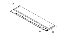
ベース板31に、反射シート32、LEDユニット33及び導光板34が組み込まれ、LEDユニット33が導光板34の側部に取り付けられると、図6に示すようにLEDユニット33が導光板34の切り欠きに収まり、面発光装置36が出来上がる。
When the
図7は、組み立て後のバックライト装置3を示す背面図である。また、図8は、図7における孔311と突出部411aの係合状態を拡大して示す背面図である。面発光装置36の上に拡散シート41、レンズシート42及びレンズシート43が取り付けられると、図8に示すように、各突出部411a、421a、431aが孔311に挿入されると共に、支持壁31aが、爪411b〜431b及び411c〜431cと辺410a〜430aとの間に介在する。そして、図8に示すように、爪411b〜431b及び411c〜431cが孔311の周囲に、支持壁31aの外側から引っかかる。
同様に、突出部412a〜432aが孔312に、突出部413a〜433aが孔313に、突出部414a〜434aが孔314にそれぞれ挿入されると共に、支持壁31aが、爪412b〜432b及び412c〜432cと辺410a〜430aとの間、爪413b〜433b及び413c〜433cと辺410a〜430aとの間、爪414b〜434b及び414c〜434cと辺410a〜430aとの間に介在する。そして、爪412b〜432b及び412c〜432cが孔312の周囲に、爪413b〜433b及び413c〜433cが孔313の周囲に、爪414b〜434b及び414c〜434cが孔314の周囲に、支持壁31aの外側からそれぞれ引っかかる。
また、レンズシート42、43がベース板31に取り付けられると、図5に示すように、プリズムパターン42aと43aとが互いに直交する。このようにしてバックライト装置3が構成されている。
FIG. 7 is a rear view showing the
Similarly, the
When the
次に、バックライト装置3が液晶ディスプレイパネル21の表示領域に光を照射する仕組みを説明する。
LEDユニット33を発光させると、その光は導光板34へ入射する。入射光は、導光板34の内部で反射を繰り返し、導光板34の上面全体が面発光して拡散シート41へと射出される。一部の光は、導光板34の下面へと洩れるが、導光板34の下面に取り付けられている反射シート32によって反射されるので、再び導光板34を透過して、拡散シート41へと射出される。
拡散シート41に入射した光は拡散されて、様々な方向を向く光となってレンズシート42へと射出される。
拡散シート41から射出された光は、レンズシート42の下面へ入射する。すると、拡散光はプリズムパターン42aで屈折し、拡散光からX方向の成分が除かれて射出される。
レンズシート42の上面から射出された光は、次にレンズシート43の下面へ入射する。すると、光はプリズムパターン43aで屈折し、光からY方向の成分が除かれて射出される。このようにして、拡散シート41から射出された拡散光は、XY平面に垂直な方向に指向性が高められた光となって液晶ディスプレイパネル21の表示領域へと射出される。
Next, a mechanism in which the
When the
The light incident on the
The light emitted from the
The light emitted from the upper surface of the
次に、バックライト装置3の製造方法について説明する。
まず、ベース板31の上面に、反射シート32を敷き、反射シート32の上に導光板34を載せる。そして導光板34の側部にLEDユニット33を取り付け、LEDユニットの上面に遮光テープ35貼り付ける。このようして面発光装置36が出来上がる。
Next, a method for manufacturing the
First, the
面発光装置36の組み立て後、導光板34の上に拡散シート41を取り付ける。まず、爪411b及び爪411cを左右から指で挟みこむようにして押し、爪411b、爪411c及び突出部411aをたわませる。そして、爪411bの突端から爪411cの突端までの距離を孔311の横幅よりも短くした状態で、突出部411a及び爪411b、411cを孔311に通す。孔311に挿入された爪411b、爪411c及び突出部411aは、再び平面状に戻り、爪411bの突端から爪411cの突端までの距離が、孔311の横幅よりも長くなる。こうして、爪411b及び爪411cが孔311の周囲に支持壁31aの外側から引っかかる。
取り付けの際は、他の突出部411a、413a、414aよりも幅広に形成されている突出部412aが目印となり、前後左右及び裏表を間違えることなく拡散シート41をベース板31に取り付けることができる。
After the surface
At the time of attachment, the
爪411b及び爪411cによって突出部411aを支持壁31a係止させたら、突出部412a〜414aも、突出部411aと同様にして孔312〜314に挿入し、爪412b〜414b及び412c〜414cを孔312〜314の周囲に引っかける。こうして拡散シート41の全ての突出部411a〜414aが支持壁31aに係止され、拡散シート41のベース板31への取り付けが完了する。
When the
拡散シート41の取り付け後、拡散シート41の上にレンズシート42を、拡散シート41と同様にしてベース板31に取り付け、レンズシート42の上にレンズシート43を拡散シート41と同様にして取り付ける。このようにしてバックライト装置3が出来上がる。
After the
一方、表示部ユニット2に、上ケース23及び下ケース24を組み付け、それにバックライト装置3を組み付ける。このようにして液晶表示装置1が完成する。
On the other hand, the
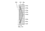
<第2の実施の形態>
図9は、突出部511aが孔311に係合している状態を拡大して示す背面図である。本実施形態の第1の実施形態との相違点は突出部及び爪の形状である。その他の構成は全て第1の実施形態で用いたものと同様である。
シート本体510の辺510aには、辺510aの内側から外側に向かう外方向に突出する突出部511aが形成されている。突出部511aは五角形をしている。
突出部511aの突端には、辺510aに沿う方向に突出する三角形の爪511b、及び爪511bの突出方向の反対方向に突出する第2の爪である爪511cが形成されている。そして、突端511dから突端511eまで成す辺511g、及び突端511dから突端511fまで成す辺511hが、突端511dから突端511e、511fに向かって辺510aに漸近するよう傾斜している。このため、突出部511aと爪511b、511cを合わせた形状は、図9に示すような略矢印型となっている。突端511eから突端511fまでの距離は、孔311の横幅よりも長くなっている。
そして、突出部511aが支持壁31aの孔311に挿入されると共に、支持壁31aが爪511b、511cと辺510aの間に介在している。そして、爪511b及び511cが孔311の周囲に、支持壁31aの外側から引っかかっている。
<Second Embodiment>
FIG. 9 is an enlarged rear view showing a state in which the protruding
On the
At the protruding end of the protruding
The
突出部511aを支持壁31aの孔311に挿入する際、まず、爪511b及び爪511cを左右から指で挟みこむようにして押し、爪511b、爪511c及び突出部511aをたわませる。そして、爪511bの突端511eから爪511cの突端511fまでの距離を孔311の横幅よりも短くした状態で、突出部511a及び爪511b、511cを孔311に通す。孔311に挿入された爪511b、爪511c及び突出部511aは、再び平面状に戻り、爪511bの突端511eから爪511cの突端511fまでの距離が、孔311の横幅よりも長くなる。こうして、爪511b及び爪511cが孔311の周囲に支持壁31aの外側から引っかかる。上記のように突出部511aの突端511dから爪の突端511e、511fまで成す辺511g、511hが、突出部511aの突端511dから爪の突端511e、511fに向かって前記シート本体510の周縁に漸近するよう傾斜する形状であることは、突端511dから挿入しやすく、引っかかりも良くなる。
When the protruding
<第3の実施の形態>
図10は、突出部611aが孔311に係合している状態を拡大して示す背面図である。本実施形態の第1、第2の実施形態との相違点は、突出部及び爪の形状と、爪の数である。その他の構成は全て第1、第2の実施形態で用いたものと同様である。
シート本体610の辺610aには、辺610aの内側から外側に向かう外方向に突出する突出部611aが形成されている。突出部611aは台形をしている。
突出部611aの突端には、辺610aに沿う方向に突出する三角形の爪611bが形成されている。そして、突端611cから突端611dまで成す辺611eが、突端611cから突端611dに向かって辺610aに漸近するよう傾斜している。このため、突出部511aと爪511bを合わせた形状は、図10に示すような略鉤爪型となっている。突端611dから辺611fまでの距離は、孔311の横幅よりも長くなっている。
そして、突出部611aが支持壁31aの孔311に挿入されると共に、支持壁31aが爪611bと辺610aの間に介在した状態となっている。そして、爪611bが孔311の周囲に、支持壁31aの外側から引っかかっている。
<Third Embodiment>
FIG. 10 is an enlarged rear view showing a state in which the protruding
On the
A
The
突出部611aを支持壁31aの孔311に挿入する際、まず、爪611b及び辺611fを左右から指で挟みこむようにして押し、爪611b、辺611f及び突出部611aをたわませる。そして、爪611bの突端611dから辺611fまでの距離を孔311の横幅よりも短くした状態で、突出部611a及び爪611bを孔311に通す。孔311に挿入された爪611b及び突出部611aは、再び平面状に戻り、爪611bの突端611dから辺611fまでの距離が、孔311の横幅よりも長くなる。こうして、爪611bが孔311の周囲に支持壁31aの外側から引っかかる。上記のように突出部611aの突端611cから爪の突端611dまで成す辺611eが、突出部611aの突端611cから爪の突端611dに向かって前記シート本体610の周縁に漸近するよう傾斜する形状であることは、突端611cから挿入しやすく、引っかかりも良くなる。また、爪の数を減らすことで光学シートに設けられる表示領域以外のスペースを最小限に抑えることができる。
When inserting the protruding
なお、各シート本体に形成される突出部は必ずしも4つずつである必要はなく、形成する数を増減させてもよい。また、対辺にそれぞれ設けられる突出部の数が必ずしも同数である必要もない。
また、爪を全ての突出部に設ける必要はなく、例えば、シート本体の中心に関して点対称の位置にある2つの突出部にのみ設けるようにしてもよい。例えば、突出部411〜431の一箇所のみを接合することとしてもよい。また、突出部411〜431及び各シート本体の中心に関して突出部411〜431と点対称となる突出部414〜434の2箇所のみ、又は突出部412〜432と点対称となる突出部413〜433の2箇所のみを接合するようにしてもよい。このように2箇所で接合しておけば各光学シート410〜430をケースから外れにくくすることができる。
また、ケースに取り付ける光学シートは拡散シートと2枚のレンズシートを合わせた3枚である必要は無く、装置によって使用する光学シートの種類を変更したり、使用する枚数を変更したりしてもよい。
また、全ての光学シートに爪を設ける必要は無く、一番上に取り付けられる光学シートにのみ設けることとしてもよい。
また、爪はあらかじめ設けずにおいて、ケースに突出部を通した後、突出部を加熱して延ばす等して爪を形成するようにしてもよい。
また、本実施形態では、突出部の一箇所のみを幅広に形成することで、前後左右及び裏表を間違えることなく光学シート積層体を確実にケースに取り付けるための目印としたが、これに限らず、突出部一箇所のみ切れ込みが入っている等、形状が異なれば良い。
Note that the number of protrusions formed on each sheet body is not necessarily four, and the number formed may be increased or decreased. Further, the number of protrusions provided on the opposite sides is not necessarily the same.
Further, it is not necessary to provide the claws on all the protrusions, and for example, the claws may be provided only on the two protrusions located in point symmetry with respect to the center of the sheet main body. For example, it is good also as joining only one place of the protrusion parts 411-431. Further, only two portions of the protruding
The optical sheet attached to the case does not need to be three sheets including the diffusion sheet and the two lens sheets. Even if the type of the optical sheet to be used is changed or the number of sheets to be used is changed depending on the apparatus. Good.
Moreover, it is not necessary to provide a nail | claw in all the optical sheets, and it is good also as providing only in the optical sheet attached to the top.
Alternatively, the claws may be formed by passing the projections through the case and then extending the projections by heating, without providing the claws in advance.
Further, in the present embodiment, only one portion of the projecting portion is formed wide so that the optical sheet laminate can be securely attached to the case without making a mistake in the front, back, left, and back, but the present invention is not limited thereto. It is sufficient that the shape is different, for example, the protrusion is cut only at one place.
本実施形態によれば、爪によって光学シートを孔の外側からケースに引っ掛けるので、光学シートに設けられる表示領域以外のスペースを最小限に抑え、ケースの大きさをほぼシート本体と同じ大きさにした状態であっても、光学シートをケースからはずれにくくすることができる。
また、突出部の突端から爪の突端まで成す辺を、突出部の突端から爪の突端に向かってシート本体の周縁に漸近するよう傾斜させることで、突出部及び爪を孔に差し込みやすくなる。
According to the present embodiment, since the optical sheet is hooked on the case from the outside of the hole by the nail, the space other than the display area provided in the optical sheet is minimized, and the size of the case is substantially the same size as the sheet body. Even in such a state, the optical sheet can be hardly detached from the case.
Further, by tilting the side formed from the protruding end of the protruding portion to the protruding end of the claw so as to approach the peripheral edge of the sheet main body from the protruding end of the protruding portion toward the protruding end of the claw, the protruding portion and the claw can be easily inserted into the hole.
1 液晶表示装置
2 表示部ユニット
21 液晶ディスプレイパネル
3 バックライト装置
31a 支持壁(支持部)
311〜314 孔
32 反射シート
33 LEDユニット
34 導光板
35 遮光テープ
36 面発光装置
41 拡散シート(光学シート)
410 シート本体
411a〜414a 突出部
411b〜414b 爪
411c〜414c 爪(第2の爪)
42、43 レンズシート(光学シート)
420、430 シート本体
421〜424a、431〜434a 突出部
421b〜424b、431a〜434b 爪
421c〜424c、431b〜434c 爪(第2の爪)
42a、43a プリズムパターン
510 シート本体
511a 突出部
511b 爪
511c 爪(第2の爪)
511d〜511f 突端
511g、511h 辺
610 シート本体
611a 突出部
611b 爪
611c、611d 突端
611e、611f 辺
DESCRIPTION OF
311 to 314
410
42, 43 Lens sheet (optical sheet)
420, 430 Sheet main body 421-424a, 431-
42a,
511d to 511f
Claims (7)
前記シート本体の周縁内側から外側に向かう外方向に、前記シート本体の周縁から突出した突出部と、
前記シート本体の周縁に沿う方向に前記突出部から突出した爪と、を備えていることを特徴とする光学シート。 The seat body,
A projecting portion projecting from the periphery of the seat body in an outward direction from the periphery of the seat body toward the outside;
An optical sheet comprising: a claw projecting from the projecting portion in a direction along the periphery of the sheet main body.
前記突出部は第1の爪が形成された第1の突出部及び第2の爪が形成された第2の突出部を備え、前記第1の突出部は前記シート本体の何れか一辺に設けられ、前記第2の突出部はその辺の対辺に設けられることを特徴とする請求項1又は2に記載の光学シート。 The shape of the seat body is a rectangle,
The protrusion includes a first protrusion formed with a first claw and a second protrusion formed with a second claw, and the first protrusion is provided on one side of the sheet body. The optical sheet according to claim 1, wherein the second projecting portion is provided on the opposite side of the side.
前記他の光学シートは爪を持たず、
前記突出部から突出した前記爪を備えた前記光学シートは前記他の光学シートの上面に積層されることを特徴とする光学シート積層体。 In the optical sheet laminate according to claim 5,
The other optical sheet does not have a nail,
The optical sheet laminate, wherein the optical sheet including the claw protruding from the protruding portion is stacked on an upper surface of the other optical sheet.
前記面発光装置の上に載せられたシート本体と、
前記シート本体の周縁内側から外側に向かう外方向に、前記シート本体の周縁から突出した突出部と、
前記シート本体の周縁に沿う方向に前記突出部から突出した爪と、
前記突出部及び前記爪が挿入される孔が形成され、前記孔に前記突出部及び前記爪が挿入されることによって前記シート本体を支持する支持部を備えることを特徴とするバックライト装置。 A surface emitting device;
A sheet body placed on the surface emitting device;
A projecting portion projecting from the periphery of the seat body in an outward direction from the periphery of the seat body toward the outside;
A claw protruding from the protruding portion in a direction along the periphery of the sheet body,
A backlight device comprising a hole into which the protruding portion and the claw are inserted, and a support portion that supports the sheet body by inserting the protruding portion and the claw into the hole.
Priority Applications (1)
| Application Number | Priority Date | Filing Date | Title |
|---|---|---|---|
| JP2009045532A JP2010197937A (en) | 2009-02-27 | 2009-02-27 | Optical sheet, optical sheet laminated body, and back light device |
Applications Claiming Priority (1)
| Application Number | Priority Date | Filing Date | Title |
|---|---|---|---|
| JP2009045532A JP2010197937A (en) | 2009-02-27 | 2009-02-27 | Optical sheet, optical sheet laminated body, and back light device |
Publications (2)
| Publication Number | Publication Date |
|---|---|
| JP2010197937A true JP2010197937A (en) | 2010-09-09 |
| JP2010197937A5 JP2010197937A5 (en) | 2011-11-17 |
Family
ID=42822684
Family Applications (1)
| Application Number | Title | Priority Date | Filing Date |
|---|---|---|---|
| JP2009045532A Pending JP2010197937A (en) | 2009-02-27 | 2009-02-27 | Optical sheet, optical sheet laminated body, and back light device |
Country Status (1)
| Country | Link |
|---|---|
| JP (1) | JP2010197937A (en) |
Cited By (1)
| Publication number | Priority date | Publication date | Assignee | Title |
|---|---|---|---|---|
| WO2017017792A1 (en) * | 2015-07-28 | 2017-02-02 | 堺ディスプレイプロダクト株式会社 | Display device |
Citations (5)
| Publication number | Priority date | Publication date | Assignee | Title |
|---|---|---|---|---|
| JPH10300933A (en) * | 1997-04-22 | 1998-11-13 | Dainippon Printing Co Ltd | Diffusion hologram optical element |
| JP2004185033A (en) * | 1996-06-25 | 2004-07-02 | Seiko Epson Corp | Polarization exchange element, polarization illumination device, and display device and projection display device using the same |
| JP2004198691A (en) * | 2002-12-18 | 2004-07-15 | Canon Inc | Optical unit for projection display |
| JP2006004751A (en) * | 2004-06-17 | 2006-01-05 | Sharp Corp | Optical sheet, backlight unit, and flat panel type display device |
| JP2007187781A (en) * | 2006-01-12 | 2007-07-26 | Sumitomo Chemical Co Ltd | Manufacturing method of optical film product |
-
2009
- 2009-02-27 JP JP2009045532A patent/JP2010197937A/en active Pending
Patent Citations (5)
| Publication number | Priority date | Publication date | Assignee | Title |
|---|---|---|---|---|
| JP2004185033A (en) * | 1996-06-25 | 2004-07-02 | Seiko Epson Corp | Polarization exchange element, polarization illumination device, and display device and projection display device using the same |
| JPH10300933A (en) * | 1997-04-22 | 1998-11-13 | Dainippon Printing Co Ltd | Diffusion hologram optical element |
| JP2004198691A (en) * | 2002-12-18 | 2004-07-15 | Canon Inc | Optical unit for projection display |
| JP2006004751A (en) * | 2004-06-17 | 2006-01-05 | Sharp Corp | Optical sheet, backlight unit, and flat panel type display device |
| JP2007187781A (en) * | 2006-01-12 | 2007-07-26 | Sumitomo Chemical Co Ltd | Manufacturing method of optical film product |
Cited By (3)
| Publication number | Priority date | Publication date | Assignee | Title |
|---|---|---|---|---|
| WO2017017792A1 (en) * | 2015-07-28 | 2017-02-02 | 堺ディスプレイプロダクト株式会社 | Display device |
| JPWO2017017792A1 (en) * | 2015-07-28 | 2018-06-28 | 堺ディスプレイプロダクト株式会社 | Display device |
| US10345646B2 (en) | 2015-07-28 | 2019-07-09 | Sakai Display Products Corporation | Display apparatus |
Similar Documents
| Publication | Publication Date | Title |
|---|---|---|
| JP5762835B2 (en) | Backlight unit and display device including the same | |
| JP5150889B2 (en) | Backlight unit and display device | |
| EP1975653A1 (en) | Backlight assembly, display apparatus having the same and method for manufacturing the same | |
| JP5535786B2 (en) | Backlight unit and liquid crystal display device | |
| JP2010040434A (en) | Surface light source device | |
| JP2009199971A (en) | Lighting device | |
| KR20160022420A (en) | Display device | |
| US8982299B2 (en) | Light emitting device comprising a plurality of fixing members disposed at different sides of a bottom cover | |
| JPWO2009130955A1 (en) | Electronic package, display device, and electronic device | |
| US10488582B2 (en) | Planar illumination apparatus | |
| JP4134072B2 (en) | Backlight unit | |
| JP2010272262A (en) | Planar illuminating device | |
| JP2019160688A (en) | Lighting device and display device including the same | |
| JP5317364B2 (en) | Backlight unit and display device | |
| CN107272257B (en) | Display device | |
| JP7303390B2 (en) | Planar lighting device | |
| WO2015025394A1 (en) | Illumination device and display device | |
| JP2010197937A (en) | Optical sheet, optical sheet laminated body, and back light device | |
| CN100514137C (en) | Display and backlight module thereof | |
| JP5386514B2 (en) | Optical assembly and display device | |
| JP2013152862A (en) | Lighting device and display device having the same | |
| JP5665623B2 (en) | Surface light unit | |
| JP2013152863A (en) | Lighting device and display device having the same | |
| KR102102909B1 (en) | Backlight unit | |
| JP2021057104A (en) | Illuminating device and display device |
Legal Events
| Date | Code | Title | Description |
|---|---|---|---|
| A521 | Written amendment |
Free format text: JAPANESE INTERMEDIATE CODE: A523 Effective date: 20110929 |
|
| A621 | Written request for application examination |
Free format text: JAPANESE INTERMEDIATE CODE: A621 Effective date: 20110929 |
|
| RD02 | Notification of acceptance of power of attorney |
Free format text: JAPANESE INTERMEDIATE CODE: A7422 Effective date: 20110929 |
|
| A977 | Report on retrieval |
Free format text: JAPANESE INTERMEDIATE CODE: A971007 Effective date: 20120711 |
|
| A131 | Notification of reasons for refusal |
Free format text: JAPANESE INTERMEDIATE CODE: A131 Effective date: 20120807 |
|
| A521 | Written amendment |
Free format text: JAPANESE INTERMEDIATE CODE: A523 Effective date: 20121004 |
|
| A131 | Notification of reasons for refusal |
Free format text: JAPANESE INTERMEDIATE CODE: A131 Effective date: 20130423 |
|
| A521 | Written amendment |
Free format text: JAPANESE INTERMEDIATE CODE: A523 Effective date: 20130621 |
|
| A131 | Notification of reasons for refusal |
Free format text: JAPANESE INTERMEDIATE CODE: A131 Effective date: 20130820 |
|
| A02 | Decision of refusal |
Free format text: JAPANESE INTERMEDIATE CODE: A02 Effective date: 20140225 |