JP2010191663A - Network management system - Google Patents
Network management system Download PDFInfo
- Publication number
- JP2010191663A JP2010191663A JP2009035088A JP2009035088A JP2010191663A JP 2010191663 A JP2010191663 A JP 2010191663A JP 2009035088 A JP2009035088 A JP 2009035088A JP 2009035088 A JP2009035088 A JP 2009035088A JP 2010191663 A JP2010191663 A JP 2010191663A
- Authority
- JP
- Japan
- Prior art keywords
- server
- network
- information
- change notification
- state change
- Prior art date
- Legal status (The legal status is an assumption and is not a legal conclusion. Google has not performed a legal analysis and makes no representation as to the accuracy of the status listed.)
- Pending
Links
- 230000005540 biological transmission Effects 0.000 claims 6
- 238000000034 method Methods 0.000 claims 5
- 238000004891 communication Methods 0.000 claims 3
Images


Landscapes
- Computer And Data Communications (AREA)
- Data Exchanges In Wide-Area Networks (AREA)
Abstract
Description
本発明は、ネットワーク管理システムに関し、特に、ネットワーク管理サーバ(以下、「サーバ」と記す)と複数台のクライアントでネットワーク機器を管理するネットワーク管理システムに関する。 The present invention relates to a network management system, and more particularly to a network management system that manages network devices with a network management server (hereinafter referred to as “server”) and a plurality of clients.
従来、ネットワーク管理システムでは、管理すべきネットワーク機器のエラー情報等の状態変化通知はサーバへ通知され、サーバにおいて一元管理していた。しかし、管理台数などが多くなってくるに従い、サーバやネットワークの負荷が重くなる問題が出てきた。 Conventionally, in a network management system, a status change notification such as error information of a network device to be managed is notified to a server and is centrally managed in the server. However, as the number of managed units increases, there has been a problem that the load on servers and networks becomes heavy.
ネットワーク機器情報が多くなりネットワークの負荷が重くなった場合に、ネットワーク機器内部にネットワーク機器情報を保存する方法(特許文献1)や、サーバとネットワーク機器間で保持する方法(特許文献2)が知られている。しかし、これらの技術は、ネットワーク機器とサーバ間の処理に対応するものであり、サーバと協働してネットワーク機器を管理するクライアント端末が増えた場合に対応するものではない。更に、ネットワーク機器情報は、ネットワーク機器やサーバとネットワーク機器間で一時的に保持されるため、サーバへ直ちに届かないのでリアルタイム性が損なわれ、サーバが正しく情報を判断できない場合が想定される。 A method for storing network device information inside the network device (Patent Document 1) and a method for storing it between the server and the network device (Patent Document 2) when the network device information increases and the load on the network becomes heavy is known. It has been. However, these technologies correspond to processing between network devices and servers, and do not correspond to the case where the number of client terminals that manage network devices in cooperation with servers increases. Furthermore, since the network device information is temporarily held between the network device or the server and the network device, it does not reach the server immediately, so the real-time property is impaired, and the server cannot correctly determine the information.
また、ネットワーク上のサービスを利用するクライアント端末が増えた場合に対応する技術であるが、サーバの提供サービス性能や通信性能の監視を行い、サーバ等における障害や性能低下の程度情報を取得し、より応答性の高い代替サービスへ切り替える方法(特許文献3)も公知である。しかし、この技術も、サーバと協働してネットワーク機器を管理するクライアント端末が増えた場合に対応するものではない。更に、代替サービス提供サーバが必要であるし、これを使用した場合には、サーバ1台で集中管理できないための時間ロスが予想され、必要な情報がクライアントへ適時に届かないという問題もある。 In addition, it is a technology that corresponds to the case where the number of client terminals that use services on the network increases, but it monitors the service performance and communication performance provided by the server, acquires information on the degree of failure and performance degradation in the server, etc. A method of switching to an alternative service with higher response (Patent Document 3) is also known. However, this technique also does not correspond to the case where the number of client terminals that manage network devices in cooperation with servers increases. Furthermore, an alternative service providing server is necessary, and when this server is used, there is a problem that time loss due to the fact that one server cannot perform centralized management is expected, and necessary information cannot be delivered to the client in a timely manner.
解決しようとする問題点は、サーバと協働してネットワーク機器を管理するクライアント端末が増えた場合、簡単な構成ではネットワーク機器情報のリアルタイム性が損なわれるという点である。 The problem to be solved is that when the number of client terminals that manage network devices in cooperation with a server increases, the real-time property of the network device information is lost with a simple configuration.
本発明は、サーバと協働してネットワーク機器を管理するクライアント端末が増えた場合、簡単な構成でネットワーク機器情報のリアルタイム性を確保するため、ネットワーク機器からの状態変化通知の発生頻度と優先度を元にサーバとクライアント間の情報の送信経路を切り替えることを最も主要な特徴とする。 When the number of client terminals that manage network devices in cooperation with a server increases, the present invention ensures the real-time property of network device information with a simple configuration. The main feature is to switch the transmission route of information between the server and the client based on the above.
本発明のネットワーク管理システムは、ネットワーク機器からの状態変化通知が増えてサーバの処理負荷が高いと判断した場合に、クライアントへの転送処理を一部クライアントに処理を移すため、サーバ側の処理を軽減できるという利点がある。但し、サーバの処理負荷が低くても、優先度の高い状態変化通知であれば、サーバから直接に全クライアントへ状態変化通知を送信する扱いとすることにより、サーバとクライアント間で同期をとることができる。 In the network management system of the present invention, when it is determined that the state change notification from the network device increases and the processing load on the server is high, the processing on the server side is transferred to a part of the transfer processing to the client. There is an advantage that it can be reduced. However, even if the processing load on the server is low, if the status change notification has a high priority, the server and the client can be synchronized by treating the server to send the status change notification directly to all clients. Can do.
ネットワークを管理するサーバはネットワーク機器情報を保持している。ネットワーク機器でエラー等が発生し機器の状態が変わった場合には、サーバに状態変化通知がネットワーク機器から送信される。サーバは状態変化通知を受けると、ネットワーク機器情報を更新し、また、サーバと協働してネットワークを管理するクライアントに対し必要に応じてネットワーク機器の状態変化通知を送信する。クライアントが複数台ある場合は、管理処理を同様に行うために全クライアントに通知が届く必要がある。 A server that manages the network holds network device information. When an error or the like occurs in the network device and the device state changes, a state change notification is transmitted from the network device to the server. When the server receives the state change notification, the server updates the network device information, and transmits a network device state change notification to the client managing the network in cooperation with the server as necessary. When there are a plurality of clients, it is necessary to notify all clients in order to perform the management process in the same manner.
本発明は、ネットワーク機器からの通知の発生頻度と通知内容の優先度によってサーバからクライアントへの通知処理を通知の態様を変えることにより、ネットワーク機器とサーバとクライアント間でネットワーク機器情報の同期性を損なわずにサーバの負荷を軽減するという目的を簡単な構成で実現した。 The present invention improves the synchronization of network device information between the network device, the server, and the client by changing the manner of notification in the notification processing from the server to the client according to the frequency of occurrence of notification from the network device and the priority of the notification content. The objective of reducing the load on the server without losing it was realized with a simple configuration.
図1は、本発明が適用されるネットワーク管理システムの一例を示す。このネットワーク管理システムは、SNMP(Simple Network Management Protcol)などのプロトコルを使用し、サーバ101にマネージャ111、ネットワーク機器105,106,107にエージェント115,116,117を有し、マネージャ111とエージェント115,116,117との間で相互に通信しながらネットワーク104の管理を行っている。
FIG. 1 shows an example of a network management system to which the present invention is applied. This network management system uses a protocol such as SNMP (Simple Network Management Protocol), the
ネットワーク機器105,106,107には、エージェント115,116,117が取得したネットワーク機器状態を保持している管理情報ベース(MIB)125,126,127を有し、サーバ101も管理情報ベース125,126,127と同内容のネットワーク機器情報121を一時保存している。このようにして、管理情報ベース125,126,127を元に、サーバ101とネットワーク機器105,106,107はネットワーク機器状態を共有している。
The
ネットワーク機器の管理ため、サーバ101側のネットワーク機器情報121と、ネットワーク機器105,106,107側の管理情報ベース125,126,127の内容は同じ状態を維持する必要がある。そのため、マネージャ111からエージェント115,116,117に対し情報取得や設定を要求するRequestを出し、その応答としてResponseがエージェント115,116,117からマネージャ111へ送出されて情報伝達がされている。また、エージェント115,116,117がエラーを検出した場合などには、自発的に状態変化通知としてサーバ101に対してTrapが送信される。Request-Responseの制御はサーバ101主体で動作しており、Trapはネットワーク機器105,106,107主体で送信されている。
In order to manage the network devices, the contents of the
ところで、管理対象となるネットワーク機器が多くなり、また、ネットワーク管理を複数の拠点で行うなどの必要性が出てきた場合は、各拠点に管理用のクライアント102,103を設置してサーバ101と接続したネットワーク管理システムを構築する。この場合、主体的にはサーバ101がネットワークを管理し、その一部管理機能であるマネージャ112,113とネットワーク機器情報121の内の一部の情報であるネットワーク機器情報122,123をクライアント102,103に持たせる。サーバ101がネットワーク機器情報121を更新する場合には、必要に応じてクライアント102,103に更新情報を送信し、ネットワーク機器情報122,123も更新される。
By the way, if there are more network devices to be managed and there is a need to perform network management at multiple bases,
ネットワーク機器が増加するのに伴い、管理情報量も増えてサーバとクライアント間の情報量が増大し、また、管理用クライアントの接続台数が増えてきて、その制御もサーバ101の負荷になってくる。特に、Trapによる状態変化通知の制御は、管理するネットワーク機器が増えてデータ量が増大してくると、1つのTrapに対しサーバ101からクライアントの接続台数分の送信が必要となりサーバ101の処理負荷となってくる。
As the number of network devices increases, the amount of management information increases, the amount of information between the server and clients increases, the number of connected management clients increases, and the control of this increases the load on the
そこで、ネットワーク機器とサーバとクライアントの間のネットワーク機器情報の同期性をなるべく損なわずにサーバの負荷を軽減する方法として本発明を提案したものである。特に、サーバと協働してネットワークを管理するクライアント台数が増えてきた場合のサーバ負荷を簡単な構成により軽減することを眼目とする。 Therefore, the present invention has been proposed as a method for reducing the load on the server without losing the synchronization of the network device information among the network device, the server, and the client as much as possible. In particular, the objective is to reduce the server load when the number of clients managing the network in cooperation with the server increases with a simple configuration.
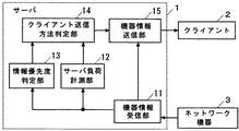
図2は、本発明の一実施例としてのサーバ1を示している。このブロック図は、図1におけるマネージャ111の詳細を示している。また、図面の煩雑化を回避するために、ネットワーク機器およびクライアントは1つだけ示している。ネットワーク機器3から状態変化通知が出されると、サーバ1内の機器情報受信部11で受信し、ネットワーク機器情報121(図2では図示省略)の更新などを行う。
FIG. 2 shows a
サーバ負荷計測部12は、機器情報受信部11から状態変化通知が発生したことを通知され、単位時間当たりの状態変化通知の発生頻度を計測し、これをサーバ1の負荷状態とする。サーバ負荷計測部12は、タイマ機能を内蔵し単位時間当たり(たとえば件/秒)の状態変化通知をカウントし続ける。計測されたカウントは、閾値を超えるような場合は高負荷状態と判断される。例えば、10件/秒を閾値とすると、12件/秒の状態変化通知が来た場合には高負荷状態と判断され、7件/秒の場合は低負荷状態と判断する。この閾値はサーバ1のCPU性能などの処理能力などによって決定する。
The server
情報優先度判定部13は、機器情報受信部11から状態変化通知の種別を受け、その内容に従って、ネットワーク機器3で発生している状態の重要度を判定し、処理優先度を決定する。クライアント送信方法判定部14は、サーバ1の負荷状態と処理優先度を元にクライアント2に対する転送有無を決定する。機器情報送信部15は、送信指示情報を状態変化通知に付加した機器情報を作成し、クライアント送信方法判定部14に従って送信する。送信は、転送無なら全クライアントに対して(図3)、転送有ならクライアント1台のみに対して(図4)行なう。
The information
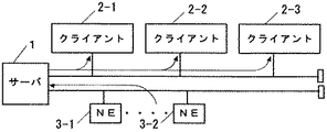
図3は状態変化通知の流れを表しており、サーバ1の負荷が軽いときや、優先度の高い状態変化通知が発生したときのものになる。ネットワーク機器3-1,3-2で状態変化通知が発生した場合、通知を受けたサーバ1から全てのクライアント2-1,2-2,2-3へ直接に状態変化通知を送信している。
FIG. 3 shows the flow of state change notification, which is when the load on the
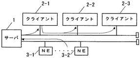
これに対し、図4はサーバ1の負荷が重く、且つ優先度の低い状態変化通知が発生したときの状態変化通知の流れを表している。ネットワーク機器3-1,3-2で状態変化通知が発生した場合、通知を受けたサーバ1はクライアント3-1に対して、状態変化通知と他のクライアントへ状態変化通知を転送する指示とを行う。クライアント3-1はサーバ1の指示により状態変化通知を他のクライアント2-2,2-3に転送する。
On the other hand, FIG. 4 shows a flow of state change notification when a load on the
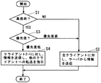
図5はクライアント送信方法判定部14における判定の手順を示すフローチャートである。サーバ1の負荷状態を判定し(図5のステップS1)、負荷が軽いようであれば全クライアント2-1,2-2,2-3に対しサーバ1から情報を送信(図3)すると決定する(ステップS2)。負荷が重い場合は情報の優先度を判定する(ステップS3)。その結果、優先度が高い場合は全クライアント2-1,2-2,2-3に対しサーバ1から情報を送信(図3)すると決定する(ステップS2)。一方、優先度が低い場合はクライアント2-1に対しのみ情報を通知し、他のクライアント2-2,2-3へは転送(図4)と決定する(ステップS4)。この決定を元に、機器情報送信部15は、クライアント送信方法判定部14で決定したクライアントへの転送情報を状態変化通知に付加した機器情報を作成し、送信方法判定部14での決定に従って、全クライアント2-1,2-2,2-3またはクライアント2-1のみに機器情報を送信する。
FIG. 5 is a flowchart showing a determination procedure in the client transmission
図6は、クライアント2-1の詳細を示すブロック図である。図6において、クライアント2-1は、他のクライアント2-2,2-3の通知先アドレス25を保持しておく。通知先アドレス25は、サーバ1から登録することで、システム構成の変更時にも対応できる。ネットワーク通信制御部21は、サーバ1から送信されてくる状態変化通知をネットワーク機器情報管理部22へ送る。ネットワーク情報管理部22は、状態変化通知に従って、ネットワーク機器の状態を記憶しているネットワーク機器情報24(図1の122,123と同じ)を更新する。
FIG. 6 is a block diagram showing details of the client 2-1. In FIG. 6, the client 2-1 holds the
また、ネットワーク情報管理部22は、状態変化通知に付加されている転送情報に従い、他クライアント2-2,2-3へ通知する必要がある場合は、クライアント制御部23へ状態変化通知を受け渡す。クライアント送信制御部23は他クライアントの通知先アドレス25を元に状態変化通知の転送処理を行って、その結果をネットワーク通信制御部21に伝える。ネットワーク通信制御部21は通知先アドレス25として登録されている全てのクライアント2-2,2-3に対して状態変化通知の転送を行う。
Further, the network
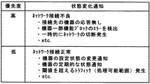
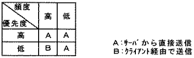
図7は、状態変化通知の具体例を優先度別に表示する。例えば、ネットワーク接続状況で分類すると、図7で分類されるようにネットワークの接続不良が起こっている状況を優先度が高いと判断し、ネットワークが接続を続けている状況は優先度が低いと判断することができる。このような状態変化通知の種類で優先度を決定するようにテーブル化しておけば、情報優先度判定部13は、このテーブルによって優先度を判定することができる。図8は、頻度と優先度を2段階に分けた送信方法の判定をまとめて表示する。図8に表示するAとBの判定がクライアント送信方法判定部14において行なわれる。
FIG. 7 displays specific examples of state change notifications by priority. For example, when classified according to the network connection status, it is determined that the network connection failure occurs as shown in FIG. 7 as high priority, and the network connection status is determined as low priority. can do. If the table is formed so that the priority is determined based on the type of state change notification, the information
以上詳述したように、サーバ1が受信する機器情報を元にクライアント2へ送信する機器情報を適切に制御することで、サーバ1の処理負荷を軽減することが可能になる。
As described above in detail, it is possible to reduce the processing load on the
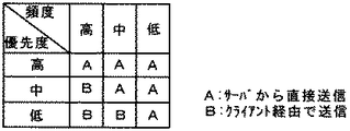
実施例1では発生頻度及び優先度を2段階に分けているが、発生頻度や優先度に関しさらに多段階に分けて送信方法の判定を行うことも考えられる。多段階に分けて判断することで、より適切にサーバ負荷を軽減することができる。頻度と優先度を3段階に分けて送信方法を判定する場合の例が図9になる。 In the first embodiment, the occurrence frequency and the priority are divided into two stages, but it is also conceivable to determine the transmission method in more stages with respect to the occurrence frequency and the priority. By making decisions in multiple stages, the server load can be reduced more appropriately. FIG. 9 shows an example in which the transmission method is determined by dividing the frequency and priority into three stages.
また、実施例1と実施例2では、クライアント1台に対し、他のクライアントへの状態変化通知の転送を指示しているがクライアントをグループ分けし、クライアント複数台に対し転送指示することも考えられる。多段階に分けた発生頻度と優先度を元にクライアントのグループ分けをフレキシブルに制御することもできる。 In the first and second embodiments, one client is instructed to transfer a state change notification to another client. However, it is also possible to divide clients into groups and instruct transfer to a plurality of clients. It is done. Client grouping can be flexibly controlled based on the occurrence frequency and priority divided into multiple stages.
1 サーバ
2 クライアント
3 ネットワーク機器
11 機器情報受信部
12 サーバ負荷計測部
13 情報優先度判別部
14 クライアント送信方法判定部
15 機器情報送信部
21 ネットワーク通信制御部
22 ネットワーク機器情報管理部
23 クライアント送信制御部
24 ネットワーク機器情報
25 通知先アドレス
2-1〜2-3 クライアント
3-1〜3-2 ネットワーク機器
101 サーバ
102,103 クライアント
104 ネットワーク
105〜107 ネットワーク機器
111〜113 マネージャ
115〜117 エージェント
121〜123 ネットワーク機器情報
125〜127 管理情報ベース
1
11 Device information receiver
12 Server load measurement section
13 Information priority discriminator
14 Client transmission method judgment part
15 Device information transmitter
21 Network communication control unit
22 Network Device Information Management Department
23 Client transmission controller
24 Network device information
25 Notification address
2-1 to 2-3 clients
3-1 to 3-2 Network equipment
101 servers
102,103 clients
104 network
105-107 network equipment
111-113 manager
115-117 agents
121-123 Network device information
125 to 127 Management information base
Claims (5)
前記サーバは、前記ネットワーク機器から各機器の状態を示すネットワーク機器状態情報を受信した場合に、その発生頻度と優先度を元に、前記ネットワーク機器状態情報を全クライアントに直接送信するか、または一部クライアントにのみ送信し他のクライアントへの転送を指示するかを判断することを特徴とするネットワーク管理システム。 Providing a plurality of clients for managing network devices in cooperation with the server under the control of the server;
When the server receives network device status information indicating the status of each device from the network device, the server directly transmits the network device status information to all clients based on the occurrence frequency and priority. A network management system for determining whether to transmit only to a client and instruct transfer to another client.
前記サーバは、ネットワーク機器情報を保持しており、
前記ネットワーク機器から状態変化通知を受信し前記ネットワーク機器情報の更新を行う機器情報受信部と、
前記機器情報受信部から状態変化通知が発生したことを通知されると、単位時間当たりの状態変化通知の発生頻度を計測るサーバ負荷計測部と、
機器情報受信部から状態変化通知の種別を受け、その内容に従って当該ネットワーク機器で発生している状態の重要度を判定し、処理優先度を決定する情報優先度判定部と、
前記発生頻度と前記処理優先度を元に一部のクライアントに対する転送有無を決定するクライアント送信方法判定部と、
前記転送無なら全クライアントへ前記状態変化通知を送信し、また前記転送有なら該転送情報を前記状態変化通知に付加した機器情報を作成し前記一部のクライアントへ送信する機器情報送信部を有することを特徴とするネットワーク管理システム。 In a network management system in which the server and a plurality of clients cooperate to manage network devices under the control of the server,
The server holds network device information,
A device information receiving unit that receives a state change notification from the network device and updates the network device information;
When notified from the device information receiving unit that a state change notification has occurred, a server load measuring unit that measures the frequency of occurrence of a state change notification per unit time; and
An information priority determination unit that receives the type of state change notification from the device information reception unit, determines the importance of the state occurring in the network device according to the content, and determines the processing priority;
A client transmission method determination unit that determines whether to transfer to some clients based on the occurrence frequency and the processing priority;
If there is no transfer, the device includes a device information transmission unit that transmits the state change notification to all clients, and if the transfer is present, creates device information with the transfer information added to the state change notification and transmits the device information to some of the clients. A network management system characterized by that.
前記サーバから送信されてくる状態変化通知を受信し、また前記転送情報に従い前記他のクライアントへ送信するネットワーク通信制御部と、
前記他のクライアントの通知先アドレスを元に状態変化通知の転送処理を行って前記ネットワーク通信制御部にクライアント送信制御部と、
前記ネットワーク通信制御部からの状態変化通知に従って前記ネットワーク機器情報を更新し、また前記転送情報に従い前記クライアント送信制御部へ状態変化通知を受け渡すネットワーク情報管理部を有することを特徴とする請求項2〜4に記載のネットワーク管理システム。 The some clients hold the network device information and notification addresses of other clients,
A network communication control unit for receiving a state change notification transmitted from the server and transmitting to the other client according to the transfer information;
Based on the notification destination address of the other client, the state change notification is transferred to the network communication control unit and the client transmission control unit,
3. The network information management unit according to claim 2, further comprising a network information management unit that updates the network device information according to a state change notification from the network communication control unit, and delivers a state change notification to the client transmission control unit according to the transfer information. The network management system according to -4.
Priority Applications (1)
| Application Number | Priority Date | Filing Date | Title |
|---|---|---|---|
| JP2009035088A JP2010191663A (en) | 2009-02-18 | 2009-02-18 | Network management system |
Applications Claiming Priority (1)
| Application Number | Priority Date | Filing Date | Title |
|---|---|---|---|
| JP2009035088A JP2010191663A (en) | 2009-02-18 | 2009-02-18 | Network management system |
Publications (1)
| Publication Number | Publication Date |
|---|---|
| JP2010191663A true JP2010191663A (en) | 2010-09-02 |
Family
ID=42817648
Family Applications (1)
| Application Number | Title | Priority Date | Filing Date |
|---|---|---|---|
| JP2009035088A Pending JP2010191663A (en) | 2009-02-18 | 2009-02-18 | Network management system |
Country Status (1)
| Country | Link |
|---|---|
| JP (1) | JP2010191663A (en) |
Cited By (2)
| Publication number | Priority date | Publication date | Assignee | Title |
|---|---|---|---|---|
| JP2021039430A (en) * | 2019-08-30 | 2021-03-11 | 富士ゼロックス株式会社 | Process display system, display terminal, process control apparatus and process display program |
| CN114740799A (en) * | 2022-04-07 | 2022-07-12 | 浙江兴达讯软件股份有限公司 | Remote monitoring method and acquisition box |
-
2009
- 2009-02-18 JP JP2009035088A patent/JP2010191663A/en active Pending
Cited By (4)
| Publication number | Priority date | Publication date | Assignee | Title |
|---|---|---|---|---|
| JP2021039430A (en) * | 2019-08-30 | 2021-03-11 | 富士ゼロックス株式会社 | Process display system, display terminal, process control apparatus and process display program |
| US11536961B2 (en) | 2019-08-30 | 2022-12-27 | Fujifilm Business Innovation Corp. | Process display system, display terminal, process management apparatus, and non-transitory computer readable medium |
| JP7379949B2 (en) | 2019-08-30 | 2023-11-15 | 富士フイルムビジネスイノベーション株式会社 | Process display system, display terminal, process control device, and process display program |
| CN114740799A (en) * | 2022-04-07 | 2022-07-12 | 浙江兴达讯软件股份有限公司 | Remote monitoring method and acquisition box |
Similar Documents
| Publication | Publication Date | Title |
|---|---|---|
| CN110912723B (en) | Communication method and device | |
| RU2651149C2 (en) | Sdn-controller, data processing center system and the routed connection method | |
| US8243594B1 (en) | Coordinated control of multiple parallel links or link aggregations | |
| CN103618621B (en) | A kind of software defined network SDN method of automatic configuration, equipment and system | |
| US8180882B2 (en) | Distributed messaging system and method for sharing network status data | |
| CN104468236B (en) | SDN controllers cluster, SDN switch and its connection control method | |
| JP6532526B2 (en) | Network control method and device | |
| EP3016316A1 (en) | Network control method and apparatus | |
| JP5464266B2 (en) | Communication system and network management method | |
| US8462636B2 (en) | Systems and methods for communication of management traffic over link aggregation group interface for a network element with distributed architecture | |
| WO2019214810A1 (en) | Management & orchestration aided transparent of 3gpp network into tsn bases industrial network | |
| CN109391503B (en) | A network slice management method and device | |
| US20130007252A1 (en) | Operations, administrations and management proxy and a method for handling operations, administrations and management messages | |
| CN106411585A (en) | Server switching method, adapter, server and scheduling device | |
| US20210083980A1 (en) | Network Traffic Throughput Forecasting | |
| US9866456B2 (en) | System and method for network health and management | |
| US10938877B2 (en) | Optimizing data transmission parameters of a proprietary network | |
| JP5574944B2 (en) | Radio relay apparatus and radio relay method | |
| RU2616880C1 (en) | Method and device for switching interface | |
| KR20040067943A (en) | Communication system and terminal | |
| KR101478944B1 (en) | Switch migration method for software-defined-networks with a plurality of controllers | |
| CN103517155A (en) | Flow dynamic control method and device based on monitor service | |
| JP2010191663A (en) | Network management system | |
| CN108667640A (en) | Communication method and equipment, network access system | |
| CN101860484A (en) | Dynamic Adjustment Method and Network Equipment of Switching Ring |