JP2010186643A - Residual capacity calculation device, vehicle having the same, and residual capacity calculation method - Google Patents
Residual capacity calculation device, vehicle having the same, and residual capacity calculation method Download PDFInfo
- Publication number
- JP2010186643A JP2010186643A JP2009030082A JP2009030082A JP2010186643A JP 2010186643 A JP2010186643 A JP 2010186643A JP 2009030082 A JP2009030082 A JP 2009030082A JP 2009030082 A JP2009030082 A JP 2009030082A JP 2010186643 A JP2010186643 A JP 2010186643A
- Authority
- JP
- Japan
- Prior art keywords
- storage device
- power storage
- remaining capacity
- power
- charged
- Prior art date
- Legal status (The legal status is an assumption and is not a legal conclusion. Google has not performed a legal analysis and makes no representation as to the accuracy of the status listed.)
- Granted
Links
Images


Classifications
-
- Y—GENERAL TAGGING OF NEW TECHNOLOGICAL DEVELOPMENTS; GENERAL TAGGING OF CROSS-SECTIONAL TECHNOLOGIES SPANNING OVER SEVERAL SECTIONS OF THE IPC; TECHNICAL SUBJECTS COVERED BY FORMER USPC CROSS-REFERENCE ART COLLECTIONS [XRACs] AND DIGESTS
- Y02—TECHNOLOGIES OR APPLICATIONS FOR MITIGATION OR ADAPTATION AGAINST CLIMATE CHANGE
- Y02E—REDUCTION OF GREENHOUSE GAS [GHG] EMISSIONS, RELATED TO ENERGY GENERATION, TRANSMISSION OR DISTRIBUTION
- Y02E60/00—Enabling technologies; Technologies with a potential or indirect contribution to GHG emissions mitigation
- Y02E60/10—Energy storage using batteries
-
- Y—GENERAL TAGGING OF NEW TECHNOLOGICAL DEVELOPMENTS; GENERAL TAGGING OF CROSS-SECTIONAL TECHNOLOGIES SPANNING OVER SEVERAL SECTIONS OF THE IPC; TECHNICAL SUBJECTS COVERED BY FORMER USPC CROSS-REFERENCE ART COLLECTIONS [XRACs] AND DIGESTS
- Y02—TECHNOLOGIES OR APPLICATIONS FOR MITIGATION OR ADAPTATION AGAINST CLIMATE CHANGE
- Y02T—CLIMATE CHANGE MITIGATION TECHNOLOGIES RELATED TO TRANSPORTATION
- Y02T10/00—Road transport of goods or passengers
- Y02T10/60—Other road transportation technologies with climate change mitigation effect
- Y02T10/62—Hybrid vehicles
Abstract
Description
この発明は、再充電可能な蓄電装置の充電状態を示す残存容量を算出する残存容量算出装置およびそれを備える車両ならびに残存容量算出方法に関する。 The present invention relates to a remaining capacity calculation device that calculates a remaining capacity indicating a charge state of a rechargeable power storage device, a vehicle including the remaining capacity calculation method, and a remaining capacity calculation method.
特許第4078847号公報(特許文献1)は、二次電池の残存容量を算出する残存容量算出装置を開示する。この残存容量算出装置においては、エンジンのクランキング開始時期には、残存容量の算出に用いられる補正量をクランキング開始時期に該当しないときに比べて増大可能なように、補正量の算出に用いられる補正ゲインが決定される。 Japanese Patent No. 4078847 (Patent Document 1) discloses a remaining capacity calculation device for calculating the remaining capacity of a secondary battery. In this remaining capacity calculation device, at the cranking start time of the engine, it is used for calculating the correction amount so that the correction amount used for calculating the remaining capacity can be increased compared to when the cranking start time does not fall. The correction gain to be determined is determined.
この残存容量算出装置によれば、車両システム停止中の二次電池の自己放電に起因して実際値から乖離した残存容量の計算値を実際値に速やかに収束させ、精度の高い残存容量を算出することができる(特許文献1参照)。 According to this remaining capacity calculation device, the calculated remaining capacity deviating from the actual value due to the self-discharge of the secondary battery when the vehicle system is stopped is quickly converged to the actual value, and the remaining capacity is calculated with high accuracy. (See Patent Document 1).
残存容量が低下すると、二次電池の過放電を防止するために、二次電池からの放電電力が制限される。ここで、残存容量が低下しているか否かは、残存容量の計算値に基づいて判断されるが、この計算値の精度が低いと、残存容量の計算値以上に実際値が低下している場合には過放電が発生し得る。すなわち、残存容量が低下しているときほど、残存容量の計算値を実際値に速やかに収束させることが要求される。上記公報では、この点についての考慮はなされていない。 When the remaining capacity decreases, the discharge power from the secondary battery is limited in order to prevent overdischarge of the secondary battery. Here, whether or not the remaining capacity is reduced is determined based on the calculated value of the remaining capacity, but if the accuracy of this calculated value is low, the actual value is lower than the calculated value of the remaining capacity. In some cases, overdischarge can occur. That is, as the remaining capacity decreases, it is required to quickly converge the calculated value of the remaining capacity to the actual value. The above publication does not consider this point.
また、残存容量の計算値を実際値に速やかに収束させるために、残存容量が低下しているか否かに拘わらず、残存容量を算出するための補正量を常時大きくすることも考えられる。しかしながら、補正量を常時大きくすることは、計算値の不安定化を招き、ひいては推定精度の低下を招く可能性がある。 Further, in order to quickly converge the calculated value of the remaining capacity to the actual value, it is conceivable to always increase the correction amount for calculating the remaining capacity regardless of whether or not the remaining capacity is lowered. However, constantly increasing the correction amount may cause the calculation value to become unstable, which may lead to a decrease in estimation accuracy.
この発明は、上記課題を解決するためになされたものであり、その目的は、残存容量推定精度の低下を防止しつつ蓄電装置の過放電を防止可能な残存容量算出装置およびそれを備える車両を提供することである。 The present invention has been made to solve the above problems, and an object of the present invention is to provide a remaining capacity calculation device capable of preventing overdischarge of a power storage device while preventing a decrease in remaining capacity estimation accuracy, and a vehicle including the same. Is to provide.
また、この発明の別の目的は、残存容量推定精度の低下を防止しつつ蓄電装置の過放電を防止可能な残存容量算出方法を提供することである。 Another object of the present invention is to provide a remaining capacity calculation method capable of preventing overdischarge of a power storage device while preventing a decrease in remaining capacity estimation accuracy.
この発明によれば、残存容量算出装置は、再充電可能な蓄電装置の充電状態を示す残存容量を算出する残存容量算出装置であって、第1および第2の推定値算出部と、充電履歴判定部と、算出部と、補正ゲイン設定部とを備える。第1の推定値算出部は、蓄電装置の充放電電流の積算値に基づいて残存容量の第1の推定値を算出する。第2の推定値算出部は、蓄電装置の電圧を用いて算出される蓄電装置の起電力に基づいて残存容量の第2の推定値を算出する。充電履歴判定部は、予め定められた所定期間における蓄電装置の充電の有無を判定する。算出部は、第1の推定値と第2の推定値との差分値および補正ゲインに基づいて算出される補正量により第1の推定値を補正することによって残存容量を算出する。補正ゲイン設定部は、充電履歴判定部によって蓄電装置の充電が無かったものと判定されたとき、その判定がなされていない場合よりも補正量を増大可能なように補正ゲインを設定する。 According to the present invention, the remaining capacity calculating device is a remaining capacity calculating device that calculates a remaining capacity indicating a charging state of a rechargeable power storage device, the first and second estimated value calculating units, a charging history A determination unit, a calculation unit, and a correction gain setting unit are provided. The first estimated value calculation unit calculates a first estimated value of the remaining capacity based on the integrated value of the charge / discharge current of the power storage device. The second estimated value calculation unit calculates a second estimated value of the remaining capacity based on the electromotive force of the power storage device calculated using the voltage of the power storage device. The charge history determination unit determines whether or not the power storage device is charged in a predetermined period. The calculation unit calculates the remaining capacity by correcting the first estimated value with a correction amount calculated based on a difference value between the first estimated value and the second estimated value and a correction gain. The correction gain setting unit sets the correction gain such that when the charging history determination unit determines that the power storage device has not been charged, the correction amount can be increased as compared with the case where the determination is not made.
好ましくは、残存容量算出装置は、異常検知部をさらに備える。異常検知部は、蓄電装置を充電する充電システムの異常を検知する。そして、充電履歴判定部は、異常検知部によって充電システムの異常が検知されたとき、蓄電装置の充電が無かったものと判定する。 Preferably, the remaining capacity calculation device further includes an abnormality detection unit. The abnormality detection unit detects an abnormality in the charging system that charges the power storage device. Then, the charging history determination unit determines that the power storage device has not been charged when an abnormality of the charging system is detected by the abnormality detection unit.
さらに好ましくは、充電システムは、内燃機関と、発電装置とを含む。発電装置は、内燃機関が発生する運動エネルギーを用いて発電し、その発電された電力を蓄電装置へ供給可能である。異常検知部は、内燃機関および発電装置の異常を検知する。そして、充電履歴判定部は、異常検知部によって内燃機関および発電装置の少なくとも一方の異常が検知されたとき、蓄電装置の充電が無かったものと判定する。 More preferably, the charging system includes an internal combustion engine and a power generation device. The power generation device can generate electric power using kinetic energy generated by the internal combustion engine, and supply the generated electric power to the power storage device. The abnormality detection unit detects an abnormality in the internal combustion engine and the power generation device. The charging history determination unit determines that the power storage device has not been charged when the abnormality detection unit detects an abnormality in at least one of the internal combustion engine and the power generation device.
好ましくは、充電履歴判定部は、当該残存容量算出装置が搭載されるシステムの起動時に判定を実施する。そして、所定期間は、システムの前回起動期間である。 Preferably, the charge history determination unit performs the determination at the time of starting the system in which the remaining capacity calculation device is mounted. The predetermined period is the previous activation period of the system.
また、この発明によれば、車両は、上述したいずれかの残存容量算出装置を備える。
また、この発明によれば、残存容量算出方法は、再充電可能な蓄電装置の充電状態を示す残存容量を算出する残存容量算出方法であって、蓄電装置の充放電電流の積算値に基づいて残存容量の第1の推定値を算出するステップと、蓄電装置の電圧を用いて算出される蓄電装置の起電力に基づいて残存容量の第2の推定値を算出するステップと、予め定められた所定期間における蓄電装置の充電の有無を判定するステップと、第1の推定値と第2の推定値との差分値および補正ゲインに基づいて算出される補正量により第1の推定値を補正することによって残存容量を算出するステップと、所定期間において蓄電装置の充電が無かったものと判定されたとき、その判定がなされていない場合よりも補正量を増大可能なように補正ゲインを設定するステップとを備える。
According to the present invention, the vehicle includes any one of the remaining capacity calculation devices described above.
According to the present invention, the remaining capacity calculation method is a remaining capacity calculation method for calculating a remaining capacity indicating a charge state of a rechargeable power storage device, and is based on an integrated value of charge / discharge currents of the power storage device. A step of calculating a first estimated value of the remaining capacity, a step of calculating a second estimated value of the remaining capacity based on the electromotive force of the power storage device calculated using the voltage of the power storage device, and a predetermined amount The first estimated value is corrected by a step of determining whether or not the power storage device is charged in a predetermined period, a correction value calculated based on a difference value between the first estimated value and the second estimated value, and a correction gain. Accordingly, the correction gain is set so that the amount of correction can be increased when it is determined that the power storage device has not been charged in a predetermined period, and when the determination is made that the determination has not been made. And a step.
好ましくは、蓄電装置を充電する充電システムの異常が検知されたとき、蓄電装置の充電の有無を判定するステップにおいて、蓄電装置の充電が無かったものと判定される。 Preferably, when an abnormality of the charging system for charging the power storage device is detected, it is determined that the power storage device has not been charged in the step of determining whether the power storage device is charged.
さらに好ましくは、充電システムは、内燃機関と、発電装置とを含む。発電装置は、内燃機関が発生する運動エネルギーを用いて発電し、その発電された電力を蓄電装置へ供給可能である。そして、内燃機関および発電装置の少なくとも一方の異常が検知されたとき、蓄電装置の充電の有無を判定するステップにおいて、蓄電装置の充電が無かったものと判定される。 More preferably, the charging system includes an internal combustion engine and a power generation device. The power generation device can generate electric power using kinetic energy generated by the internal combustion engine, and supply the generated electric power to the power storage device. When an abnormality in at least one of the internal combustion engine and the power generation device is detected, it is determined in the step of determining whether or not the power storage device is charged, that the power storage device is not charged.
好ましくは、蓄電装置の充電の有無を判定するステップにおいて、当該残存容量算出方法が適用されるシステムの起動時に判定が実施される。そして、所定期間は、システムの前回起動期間である。 Preferably, in the step of determining whether or not the power storage device is charged, the determination is performed when the system to which the remaining capacity calculation method is applied is started. The predetermined period is the previous activation period of the system.
この残存容量算出装置およびそれを備える車両ならびに残存容量算出方法においては、所定期間において蓄電装置の充電が無かったものと判定されると、蓄電装置の充電が行なわれていないことにより残存容量の低下のおそれがあるものと判断され、上記の判定がなされていない場合よりも補正量を増大可能なように補正ゲインが設定される。所定期間において蓄電装置の充電は有ったと判定された場合には、補正量を増大可能なような補正ゲインの設定は行なわれない。 In the remaining capacity calculating device, the vehicle including the remaining capacity calculating method, and the remaining capacity calculating method, if it is determined that the power storage device has not been charged in a predetermined period, the remaining capacity is reduced because the power storage device is not charged. The correction gain is set so that the correction amount can be increased as compared with the case where the above determination is not made. When it is determined that the power storage device has been charged in the predetermined period, the correction gain that can increase the correction amount is not set.
したがって、この残存容量算出装置およびそれを備える車両ならびに残存容量算出方法によれば、残存容量推定精度の低下を防止しつつ蓄電装置の過放電を防止することができる。 Therefore, according to the remaining capacity calculation device, the vehicle including the remaining capacity calculation method, and the remaining capacity calculation method, it is possible to prevent overdischarge of the power storage device while preventing a decrease in remaining capacity estimation accuracy.
以下、本発明の実施の形態について、図面を参照しながら詳細に説明する。なお、図中同一または相当部分には同一符号を付してその説明は繰返さない。 Hereinafter, embodiments of the present invention will be described in detail with reference to the drawings. In the drawings, the same or corresponding parts are denoted by the same reference numerals and description thereof will not be repeated.
図1は、この発明の実施の形態による残存容量算出装置が搭載される車両の全体ブロック図である。図1を参照して、車両100は、蓄電装置6と、コンバータ8と、平滑コンデンサCと、インバータ20−1,20−2と、モータジェネレータMG1,MG2と、エンジン22と、動力分割装置24と、駆動輪26とを備える。また、車両100は、電池ECU(Electronic Control Unit)30と、MG−ECU32と、電流センサ10と、電圧センサ12,18とをさらに備える。
FIG. 1 is an overall block diagram of a vehicle equipped with a remaining capacity calculation device according to an embodiment of the present invention. Referring to FIG. 1,
蓄電装置6は、再充電可能な直流電源であり、たとえば、リチウムイオン電池やニッケル水素電池などの二次電池から成る。蓄電装置6は、正極線PLおよび負極線NLを介してコンバータ8に接続される。 The power storage device 6 is a rechargeable DC power source, and is composed of, for example, a secondary battery such as a lithium ion battery or a nickel hydride battery. Power storage device 6 is connected to converter 8 through positive electrode line PL and negative electrode line NL.
電流センサ10は、蓄電装置6に対して入出力される電流Ibを検出し、その検出値を電池ECU30およびMG−ECU32へ出力する。なお、電流センサ10は、蓄電装置6から出力される電流(放電電流)を正値として検出し、蓄電装置6に入力される電流(充電電流)を負値として検出する。また、図1では、電流センサ10が正極線PLの電流を検出する場合が示されているが、電流センサ10は、負極線NLの電流を検出してもよい。電圧センサ12は、正極線PLと負極線NLとの間の電圧すなわち蓄電装置6の電圧Vbを検出し、その検出値を電池ECU30およびMG−ECU32へ出力する。
コンバータ8は、蓄電装置6と主正母線MPLおよび主負母線MNLとの間に設けられ、MG−ECU32からの駆動信号PWCに基づいて、蓄電装置6と主正母線MPLおよび主負母線MNLとの間で電圧変換を行なう。コンバータ8は、たとえば、昇降圧型のチョッパ回路から成る。平滑コンデンサCは、主正母線MPLと主負母線MNLとの間に接続され、主正母線MPLおよび主負母線MNLに含まれる電力変動成分を低減する。電圧センサ18は、主正母線MPLと主負母線MNLとの間の電圧Vhを検出し、その検出値をMG−ECU32へ出力する。
インバータ20−1,20−2は、主正母線MPLおよび主負母線MNLに互いに並列して接続される。そして、インバータ20−1,20−2は、主正母線MPLおよび主負母線MNLから供給される駆動電力(直流電力)を交流電力に変換してそれぞれモータジェネレータMG1,MG2へ出力する。また、インバータ20−1,20−2は、それぞれモータジェネレータMG1,MG2が発電する交流電力を直流電力に変換して回生電力として主正母線MPLおよび主負母線MNLへ出力する。インバータ20−1,20−2は、たとえば、三相ブリッジ回路から成る。 Inverters 20-1 and 20-2 are connected in parallel to main positive bus MPL and main negative bus MNL. Inverters 20-1 and 20-2 convert drive power (DC power) supplied from main positive bus MPL and main negative bus MNL into AC power and output the AC power to motor generators MG1 and MG2, respectively. Inverters 20-1 and 20-2 convert AC power generated by motor generators MG1 and MG2 into DC power, respectively, and output the power as regenerative power to main positive bus MPL and main negative bus MNL. Inverters 20-1 and 20-2 are formed of, for example, a three-phase bridge circuit.
モータジェネレータMG1,MG2は、三相交流電動機であり、たとえば三相交流同期電動機から成る。モータジェネレータMG1は、エンジン22が発生する運動エネルギーを用いて発電し、その発電した電力をインバータ20−1へ出力する。また、モータジェネレータMG1は、インバータ20−1から受ける三相交流電力によって駆動力を発生し、エンジン22の始動を行なう。モータジェネレータMG2は、インバータ20−2から受ける三相交流電力によって車両の駆動トルクを発生する。モータジェネレータMG2によって発生された駆動トルクは、駆動輪26へ伝達される。また、モータジェネレータMG2は、車両の制動時、駆動輪26から受ける車両の運動エネルギーを用いて発電し、その発電した電力をインバータ20−2へ出力する。
Motor generators MG1 and MG2 are three-phase AC motors, for example, three-phase AC synchronous motors. Motor generator MG1 generates electric power using kinetic energy generated by
動力分割装置24は、エンジン22とモータジェネレータMG1,MG2とに結合されてこれらの間で動力を分配する。たとえば、動力分割装置24として、サンギヤ、プラネタリキャリヤおよびリングギヤの3つの回転軸を有する遊星歯車を用いることができる。この3つの回転軸がエンジン22およびモータジェネレータMG1,MG2の各回転軸にそれぞれ接続される。たとえば、モータジェネレータMG1のロータを中空としてその中心にエンジン22のクランク軸を通すことで動力分割装置24にエンジン22とモータジェネレータMG1,MG2とを機械的に接続することができる。
Power split
エンジン22が発生する動力は、動力分割装置24によって駆動輪26とモータジェネレータMG1とに分配される。すなわち、エンジン22は、駆動輪26を駆動するとともにモータジェネレータMG1を駆動する動力源として車両100に組込まれる。また、モータジェネレータMG1は、エンジン22によって駆動される発電機として動作し、かつ、エンジン22の始動を行ない得る電動機として動作するものとして車両100に組込まれ、モータジェネレータMG2は、駆動輪26を駆動する動力源として車両100に組込まれる。
The power generated by the
MG−ECU32は、モータジェネレータMG1の発生トルクおよび回転数が目標値に一致するように駆動信号PWI1を生成し、その生成した駆動信号PWI1をインバータ20−1へ出力する。また、MG−ECU32は、モータジェネレータMG2の発生トルクおよび回転数が目標値に一致するように駆動信号PWI2を生成し、その生成した駆動信号PWI2をインバータ20−2へ出力する。さらに、MG−ECU32は、コンバータ8を駆動するための駆動信号PWCを生成し、その生成した駆動信号PWCをコンバータ8へ出力する。
MG-
また、さらに、MG−ECU32は、エンジン22、モータジェネレータMG1、インバータ20−1およびコンバータ8から成る充電システムにおいて異常を検知すると、電池ECU30へ出力される異常検知フラグABNLを活性化する。詳しくは、MG−ECU32は、モータジェネレータMG1、インバータ20−1およびコンバータ8の少なくとも一つにおいて異常を検知すると、異常検知フラグABNLを活性化する。
Further, MG-
電池ECU30は、車両100の起動/停止状態を示すイグニッション信号IGを受け、MG−ECU32から異常検知フラグABNLを受ける。また、電池ECU30は、電流センサ10から電流Ibの検出値を受け、電圧センサ12から電圧Vbの検出値を受ける。そして、電池ECU30は、これらの各信号に基づいて、後述の方法により、蓄電装置6の充電状態を示す残存容量を算出する。なお、残存容量は、たとえば満充電状態を100%として百分率で示される。以下では、残存容量を「SOC(State Of Charge)」とも称する。
また、電池ECU30は、蓄電装置6のSOCに基づいて、蓄電装置6の放電電力(kW)を制限するための放電電力制限値Wout、および蓄電装置6の充電電力(kW)を制限するための充電電力制限値Winを設定する。
図2は、図1に示した電池ECU30により設定される放電電力制限値Woutおよび充電電力制限値Winを示した図である。図2を参照して、横軸は、蓄電装置6のSOC(%)を示し、縦軸は、蓄電装置6の充放電電力(kW)を示す。なお、電力が正値であることは放電電力を示し、電力が負値であることは充電電力を示す。
FIG. 2 is a diagram showing discharge power limit value Wout and charge power limit value Win set by
図2に示されるように、SOCが所定値を下回ると、蓄電装置6の過放電を防止するために放電電力制限値Woutが絞られる。なお、SOCが所定値を超えると、蓄電装置6の過充電を防止するために充電電力制限値Winが絞られる。 As shown in FIG. 2, when SOC falls below a predetermined value, discharge power limit value Wout is reduced to prevent overdischarge of power storage device 6. When SOC exceeds a predetermined value, charging power limit value Win is reduced in order to prevent overcharging of power storage device 6.
そして、この放電電力制限値Woutおよび充電電力制限値Winを超えないように、蓄電装置6の充放電が制御される。 Charging / discharging of power storage device 6 is controlled so as not to exceed discharge power limit value Wout and charge power limit value Win.
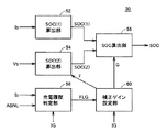
図3は、図1に示した電池ECU30の機能ブロック図である。なお、この図3では、電池ECU30の機能のうち、SOCの算出に関する部分が示される。図3を参照して、電池ECU30は、SOC(1)算出部52と、SOC(2)算出部54と、SOC算出部56と、充電履歴判定部58と、補正ゲイン設定部60とを含む。
FIG. 3 is a functional block diagram of
SOC(1)算出部52は、蓄電装置6の充放電電流を示す電流Ibの積算値を算出する。そして、SOC(1)算出部52は、その算出された電流積算値に基づいて、SOCの第1の推定値SOC(1)を算出する。
The SOC (1)
SOC(2)算出部54は、蓄電装置6の電圧Vbを用いて蓄電装置6の起電力を算出し、その算出された起電力に基づいて、SOCの第2の推定値SOC(2)を算出する。詳しくは、SOC(2)算出部54は、まず、第1の起電力V(1)を次式によって算出する。
SOC (2)
V(1)=Vb−分極電圧−内部抵抗電圧低下 …(1)
なお、分極電圧および内部抵抗電圧低下は、たとえば電流Ibに基づいて算出される。
V (1) = Vb−polarization voltage−internal resistance voltage drop (1)
The polarization voltage and the internal resistance voltage drop are calculated based on the current Ib, for example.
次いで、SOC(2)算出部54は、第1の起電力V(1)を減衰処理した第2の起電力V(2)を次式によって算出する。
Next, the SOC (2)
V(2)=V(0)+{T/τ×(V(1)−V(0))} …(2)
ここで、Tは演算周期であり、V(0)は前回演算時に算出された起電力V(2)である。また、τは時定数であり、後述の補正ゲイン設定部60により設定される。
V (2) = V (0) + {T / τ × (V (1) −V (0))} (2)
Here, T is the calculation cycle, and V (0) is the electromotive force V (2) calculated during the previous calculation. Further, τ is a time constant and is set by a correction
そして、SOC(2)算出部54は、蓄電装置6の起電力とSOCとの関係を示す予め準備された起電力−SOCマップを用いて、第2の起電力V(2)に基づいて第2の推定値SOC(2)を算出する。
Then, the SOC (2) calculating
SOC算出部56は、SOC(1)算出部52により算出された第1の推定値SOC(1)とSOC(2)算出部54により算出された第2の推定値SOC(2)との差分値ΔSOCに、補正ゲイン設定部60により設定される補正ゲインGを乗算して補正量Cを算出する。そして、SOC算出部56は、その算出された補正量Cを第1の推定値SOC(1)に加算することにより、最終的なSOCを算出する。
The
充電履歴判定部58は、車両システムが起動されてから停止するまでの1トリップ中における蓄電装置6の充電の有無(充電履歴)を判定する。たとえば、充電履歴判定部58は、電流Ibの検出値を用いて1トリップ中の充電電流を積算し、その積算値が所定値よりも小さいとき、蓄電装置6の充電が無かったものと判定する。なお、車両システムの起動/停止は、イグニッション信号IGに基づいて判断される。
The charge
充電履歴判定部58は、蓄電装置6の充電が無かったものと判定すると(充電履歴無し)、補正ゲイン設定部60へ出力される充電履歴フラグFLGをOFFにする。一方、蓄電装置6の充電が有ったものと判定されると(充電履歴有り)、充電履歴判定部58は、充電履歴フラグFLGをONにする。
When charging
なお、充電履歴判定部58は、車両システムの起動中、充電有無の判定を実施し、車両システムの停止時、充電履歴フラグFLGを不揮発性のメモリ等に記憶する。そして、次回システムの起動時、記憶された充電履歴フラグFLGを読出して補正ゲイン設定部60へ出力する。
The charging
なお、MG−ECU32からの異常検知フラグABNLが活性化されている場合、すなわち蓄電装置6の充電システムの異常が検知されている場合、蓄電装置6の充電が不可能であると判断し、充電履歴フラグFLGをOFFしてもよい。すなわち、充電履歴フラグFLGは、充電電流の積算値に基づき充電が実際に行なわれていないときにOFFしてもよいし、異常検知フラグABNLに基づき充電不可能と判断できるときにOFFしてもよい。
When abnormality detection flag ABNL from MG-
補正ゲイン設定部60は、SOC算出部56においてSOCの算出に用いられる補正ゲインGを設定する。ここで、補正ゲイン設定部60は、通常は補正ゲインGとしてG1を設定する。一方、補正ゲイン設定部60は、車両システムの起動時、充電履歴判定部58から受ける充電履歴フラグFLGがOFFであると、G1よりも大きいG2を補正ゲインGとして設定する。なお、車両システムの起動は、イグニッション信号IGに基づいて判定される。
The correction
なお、補正ゲイン設定部60は、SOC(2)算出部54において用いられる時定数τも設定する。補正ゲイン設定部60は、通常は時定数τとしてτ1を設定する。一方、補正ゲイン設定部60は、車両システムの起動時に充電履歴フラグFLGがOFFのとき、τ1よりも小さいτ2を時定数τとして設定する。
The correction
図4は、SOCの算出手順を示すフローチャートである。なお、このフローチャートに示される処理手順は、一定時間毎または所定の条件が成立する毎に実行される。 FIG. 4 is a flowchart showing the SOC calculation procedure. Note that the processing procedure shown in this flowchart is executed at regular time intervals or whenever a predetermined condition is satisfied.
図4を参照して、電池ECU30は、電流センサ10によって検出される蓄電装置6の電流Ibを用いて、上述の手法により第1の推定値SOC(1)を算出する(ステップS10)。
Referring to FIG. 4,
次いで、電池ECU30は、SOCを算出するための補正パラメータ(補正ゲインG、時定数τ)を設定する補正ゲイン設定処理を実行する(ステップS20)。なお、この補正ゲイン設定処理はサブルーチン化され、詳細は後ほど説明する。
Next, the
次いで、電池ECU30は、上述の(1)式を用いて、電圧センサ12によって検出される蓄電装置6の電圧Vbを用いて第1の起電力V(1)を算出する(ステップS30)。さらに次いで、電池ECU30は、上述の(2)式を用いて、ステップS20において設定された時定数τおよびステップS30において算出された第1の起電力V(1)に基づいて第2の起電力V(2)を算出する(ステップS40)。そして、電池ECU30は、予め準備された起電力−SOCマップを用いて、ステップS40において算出された第2の起電力V(2)に基づいて第2の推定値SOC(2)を算出する(ステップS50)。
Next, the
続いて、電池ECU30は、ステップS10において算出された第1の推定値SOC(1)と、ステップS50において算出された第2の推定値SOC(2)との差分値ΔSOCを算出する(ステップS60)。さらに、電池ECU30は、その算出された差分値ΔSOCに、ステップS20において設定された補正ゲインGを乗算することによって、補正量Cを算出する(ステップS70)。
Subsequently, the
そして、電池ECU30は、ステップS10において算出された第1の推定値SOC(1)に、ステップS70において算出された補正量Cを加算することによって、最終的なSOCを算出する(ステップS80)。
Then, the
図5は、図4に示した補正ゲイン設定処理の手順を示すフローチャートである。なお、このフローチャートに示される処理手順は、図4に示したメインルーチンから呼出されて実行される。 FIG. 5 is a flowchart showing the procedure of the correction gain setting process shown in FIG. The processing procedure shown in this flowchart is called and executed from the main routine shown in FIG.
図5を参照して、電池ECU30は、車両システムが起動してから所定時間が経過したか否かを判定する(ステップS110)。車両システムの起動後所定時間が経過しているときは(ステップS110においてYES)、電池ECU30は、ステップS130へ処理を移行し、補正ゲインGにG(1)を設定し、時定数τにτ(1)を設定する(ステップS130)。
Referring to FIG. 5,
ステップS110において、車両システムが起動してから所定時間が経過していないと判定されると(ステップS110においてNO)、電池ECU30は、充電履歴フラグFLGがOFFであるか否かを判定する(ステップS120)。上述のように、この充電履歴フラグFLGは、前回のトリップにおける蓄電装置6の充電の有無を示すフラグである。なお、充電履歴フラグFLGは、蓄電装置6を充電する充電システム(エンジン22、モータジェネレータMG1、インバータ20−1、コンバータ8等)の異常に起因して蓄電装置6の充電が不可能であることを示すものであってもよい。
If it is determined in step S110 that the predetermined time has not elapsed since the vehicle system was activated (NO in step S110),
そして、充電履歴フラグFLGがOFFのとき(ステップS120においてYES)、電池ECU30は、補正ゲインGにG(2)(>G(1))を設定し、時定数τにτ(2)(<τ(1))を設定する(ステップS140)。一方、充電履歴フラグFLGがONのときは(ステップS120においてNO)、ステップS130へ処理が移行され、補正ゲインGおよび時定数τにそれぞれG(1),τ(1)が設定される。
When charging history flag FLG is OFF (YES in step S120),
図6は、SOCの時間的変化を示した図である。なお、比較のため、従来のSOCの時間的変化を図7に示す。図6を参照して、時刻t1において、車両システムが起動される。このとき、充電履歴フラグFLGがOFFしているので、SOCを算出するための補正量が増大可能なように補正パラメータが設定される。具体的には、補正ゲインGにG(2)(>G(1))が設定され、時定数τにτ(2)(<τ(1))が設定される。これにより、低下している実績値から乖離していた計算値が真値へ速やかに収束する。一方、図7に示される従来手法では、計算値の真値への収束が遅く、蓄電装置6が過放電になる可能性がある。 FIG. 6 is a diagram showing a change in SOC over time. For comparison, FIG. 7 shows a temporal change in the conventional SOC. Referring to FIG. 6, the vehicle system is activated at time t1. At this time, since the charging history flag FLG is OFF, the correction parameter is set so that the correction amount for calculating the SOC can be increased. Specifically, G (2) (> G (1)) is set as the correction gain G, and τ (2) (<τ (1)) is set as the time constant τ. As a result, the calculated value deviating from the decreasing actual value quickly converges to the true value. On the other hand, in the conventional method shown in FIG. 7, the convergence of the calculated value to the true value is slow, and the power storage device 6 may be overdischarged.
なお、時刻t1から所定時間T経過後の時刻t2において、補正パラメータは通常の値に戻される。すなわち、補正ゲインGにG(1)が設定され、時定数τにτ(1)が設定される。 Note that the correction parameter is returned to a normal value at time t2 after a predetermined time T has elapsed from time t1. That is, G (1) is set for the correction gain G, and τ (1) is set for the time constant τ.
以上のように、この実施の形態においては、車両システムの起動時、前回トリップにおいて蓄電装置6の充電が無かったものと判定され、あるいは充電システムの異常により蓄電装置6の充電が不可能であると判定されると、蓄電装置6の充電が行なわれていないことによりSOCの低下のおそれがあるものと判断され、上記の判定がなされていない場合よりも補正量Cを増大可能なように補正パラメータ(補正ゲインG、時定数τ)が設定される。したがって、この実施の形態によれば、SOC推定精度の低下を防止しつつ蓄電装置6の過放電を防止することができる。 As described above, in this embodiment, when the vehicle system is started, it is determined that the power storage device 6 has not been charged in the previous trip, or the power storage device 6 cannot be charged due to an abnormality in the charging system. If it is determined that the power storage device 6 is not charged, it is determined that there is a risk of a decrease in SOC, and the correction amount C is corrected so that the correction amount C can be increased as compared with the case where the above determination is not performed. Parameters (correction gain G, time constant τ) are set. Therefore, according to this embodiment, overdischarge of power storage device 6 can be prevented while preventing a decrease in SOC estimation accuracy.
なお、上記の実施の形態においては、電池ECU30とMG−ECU32とを別個に構成するものとしたが、電池ECU30とMG−ECU32とを一つのECUで構成してもよい。
In the above embodiment, the
また、上記においては、車両100は、動力分割装置24によりエンジン22の動力を分割して駆動輪26とモータジェネレータMG1とに伝達可能なシリーズ/パラレル型のハイブリッド自動車として説明したが、この発明は、その他の形式のハイブリッド自動車にも適用可能である。たとえば、モータジェネレータMG1を駆動するためにのみエンジン22を用い、モータジェネレータMG2でのみ車両の駆動力を発生する、いわゆるシリーズ型のハイブリッド自動車や、エンジン22が生成した運動エネルギーのうち回生エネルギーのみが電気エネルギーとして回収されるハイブリッド自動車、エンジンを主動力として必要に応じてモータがアシストするモータアシスト型のハイブリッド自動車などにもこの発明は適用可能である。
In the above description,
また、この発明は、エンジン22を備えずに電力のみで走行する電気自動車や、電源として蓄電装置に加えて燃料電池をさらに備える燃料電池車にも適用可能である。さらに、この発明は、コンバータ8を備えないシステムにも適用可能である。
The present invention is also applicable to an electric vehicle that does not include the
なお、上記において、SOC(1)算出部52は、この発明における「第1の推定値算出部」に対応し、SOC(2)算出部54は、この発明における「第2の推定値算出部」に対応する。また、SOC算出部56は、この発明における「算出部」に対応し、MG−ECU32は、この発明における「異常検知部」に対応する。
In the above description, the SOC (1) calculating
今回開示された実施の形態は、すべての点で例示であって制限的なものではないと考えられるべきである。本発明の範囲は、上記した実施の形態の説明ではなくて特許請求の範囲によって示され、特許請求の範囲と均等の意味および範囲内でのすべての変更が含まれることが意図される。 The embodiment disclosed this time should be considered as illustrative in all points and not restrictive. The scope of the present invention is shown not by the above description of the embodiments but by the scope of claims for patent, and is intended to include meanings equivalent to the scope of claims for patent and all modifications within the scope.
6 蓄電装置、8 コンバータ、10 電流センサ、12,18 電圧センサ、20−1,20−2 インバータ、22 エンジン、24 動力分割装置、26 駆動輪、30 電池ECU、32 MG−ECU、52 SOC(1)算出部、54 SOC(2)算出部、56 SOC算出部、58 充電履歴判定部、60 補正ゲイン設定部、100 車両、PL 正極線、NL 負極線、MPL 主正母線、MNL 主負母線、C 平滑コンデンサ、MG1,MG2 モータジェネレータ。 6 power storage device, 8 converter, 10 current sensor, 12, 18 voltage sensor, 20-1, 20-2 inverter, 22 engine, 24 power split device, 26 driving wheel, 30 battery ECU, 32 MG-ECU, 52 SOC ( 1) calculation unit, 54 SOC (2) calculation unit, 56 SOC calculation unit, 58 charge history determination unit, 60 correction gain setting unit, 100 vehicle, PL positive line, NL negative line, MPL main positive bus, MNL main negative bus , C Smoothing capacitor, MG1, MG2 Motor generator.
Claims (9)
前記蓄電装置の充放電電流の積算値に基づいて前記残存容量の第1の推定値を算出する第1の推定値算出部と、
前記蓄電装置の電圧を用いて算出される前記蓄電装置の起電力に基づいて前記残存容量の第2の推定値を算出する第2の推定値算出部と、
予め定められた所定期間における前記蓄電装置の充電の有無を判定する充電履歴判定部と、
前記第1の推定値と前記第2の推定値との差分値および補正ゲインに基づいて算出される補正量により前記第1の推定値を補正することによって前記残存容量を算出する算出部と、
前記充電履歴判定部によって前記蓄電装置の充電が無かったものと判定されたとき、その判定がなされていない場合よりも前記補正量を増大可能なように前記補正ゲインを設定する補正ゲイン設定部とを備える残存容量算出装置。 A remaining capacity calculation device for calculating a remaining capacity indicating a charge state of a rechargeable power storage device,
A first estimated value calculating unit that calculates a first estimated value of the remaining capacity based on an integrated value of the charge / discharge current of the power storage device;
A second estimated value calculation unit that calculates a second estimated value of the remaining capacity based on the electromotive force of the power storage device calculated using the voltage of the power storage device;
A charge history determination unit that determines whether or not the power storage device is charged in a predetermined period of time;
A calculating unit that calculates the remaining capacity by correcting the first estimated value by a correction amount calculated based on a difference value and a correction gain between the first estimated value and the second estimated value;
A correction gain setting unit that sets the correction gain so that the correction amount can be increased when the charge history determination unit determines that the power storage device has not been charged, compared to a case where the determination is not made; A remaining capacity calculation device.
前記充電履歴判定部は、前記異常検知部によって前記充電システムの異常が検知されたとき、前記蓄電装置の充電が無かったものと判定する、請求項1に記載の残存容量算出装置。 Further comprising an abnormality detection unit for detecting an abnormality of a charging system for charging the power storage device;
The remaining capacity calculation device according to claim 1, wherein the charging history determination unit determines that the power storage device has not been charged when an abnormality of the charging system is detected by the abnormality detection unit.
内燃機関と、
前記内燃機関が発生する運動エネルギーを用いて発電し、その発電された電力を前記蓄電装置へ供給可能な発電装置とを含み、
前記異常検知部は、前記内燃機関および前記発電装置の異常を検知し、
前記充電履歴判定部は、前記異常検知部によって前記内燃機関および前記発電装置の少なくとも一方の異常が検知されたとき、前記蓄電装置の充電が無かったものと判定する、請求項2に記載の残存容量算出装置。 The charging system includes:
An internal combustion engine;
A power generator that generates power using kinetic energy generated by the internal combustion engine, and that can supply the generated power to the power storage device,
The abnormality detection unit detects an abnormality in the internal combustion engine and the power generation device,
The remaining charge according to claim 2, wherein the charge history determination unit determines that the power storage device has not been charged when an abnormality of at least one of the internal combustion engine and the power generation device is detected by the abnormality detection unit. Capacity calculation device.
前記所定期間は、前記システムの前回起動期間である、請求項1に記載の残存容量算出装置。 The charging history determination unit performs the determination at the time of starting the system in which the remaining capacity calculation device is mounted,
The remaining capacity calculation apparatus according to claim 1, wherein the predetermined period is a previous activation period of the system.
前記蓄電装置の充放電電流の積算値に基づいて前記残存容量の第1の推定値を算出するステップと、
前記蓄電装置の電圧を用いて算出される前記蓄電装置の起電力に基づいて前記残存容量の第2の推定値を算出するステップと、
予め定められた所定期間における前記蓄電装置の充電の有無を判定するステップと、
前記第1の推定値と前記第2の推定値との差分値および補正ゲインに基づいて算出される補正量により前記第1の推定値を補正することによって前記残存容量を算出するステップと、
前記所定期間において前記蓄電装置の充電が無かったものと判定されたとき、その判定がなされていない場合よりも前記補正量を増大可能なように前記補正ゲインを設定するステップとを備える残存容量算出方法。 A remaining capacity calculation method for calculating a remaining capacity indicating a charging state of a rechargeable power storage device,
Calculating a first estimated value of the remaining capacity based on an integrated value of charge / discharge current of the power storage device;
Calculating a second estimated value of the remaining capacity based on the electromotive force of the power storage device calculated using the voltage of the power storage device;
Determining whether or not the power storage device is charged during a predetermined period;
Calculating the remaining capacity by correcting the first estimated value by a correction amount calculated based on a difference value between the first estimated value and the second estimated value and a correction gain;
When it is determined that the power storage device is not charged in the predetermined period, the remaining capacity calculation includes a step of setting the correction gain so that the correction amount can be increased as compared with a case where the determination is not performed. Method.
内燃機関と、
前記内燃機関が発生する運動エネルギーを用いて発電し、その発電された電力を前記蓄電装置へ供給可能な発電装置とを含み、
前記内燃機関および前記発電装置の少なくとも一方の異常が検知されたとき、前記蓄電装置の充電の有無を判定するステップにおいて、前記蓄電装置の充電が無かったものと判定される、請求項7に記載の残存容量算出方法。 The charging system includes:
An internal combustion engine;
A power generator that generates power using kinetic energy generated by the internal combustion engine, and that can supply the generated power to the power storage device,
8. The method according to claim 7, wherein when the abnormality of at least one of the internal combustion engine and the power generation device is detected, in the step of determining whether or not the power storage device is charged, it is determined that the power storage device is not charged. Remaining capacity calculation method.
前記所定期間は、前記システムの前回起動期間である、請求項6に記載の残存容量算出方法。 In the step of determining whether or not the power storage device is charged, determination is performed at the time of starting the system to which the remaining capacity calculation method is applied,
The remaining capacity calculation method according to claim 6, wherein the predetermined period is a previous activation period of the system.
Priority Applications (1)
| Application Number | Priority Date | Filing Date | Title |
|---|---|---|---|
| JP2009030082A JP5310054B2 (en) | 2009-02-12 | 2009-02-12 | Remaining capacity calculation device, vehicle equipped with the same, and remaining capacity calculation method |
Applications Claiming Priority (1)
| Application Number | Priority Date | Filing Date | Title |
|---|---|---|---|
| JP2009030082A JP5310054B2 (en) | 2009-02-12 | 2009-02-12 | Remaining capacity calculation device, vehicle equipped with the same, and remaining capacity calculation method |
Publications (2)
| Publication Number | Publication Date |
|---|---|
| JP2010186643A true JP2010186643A (en) | 2010-08-26 |
| JP5310054B2 JP5310054B2 (en) | 2013-10-09 |
Family
ID=42767179
Family Applications (1)
| Application Number | Title | Priority Date | Filing Date |
|---|---|---|---|
| JP2009030082A Expired - Fee Related JP5310054B2 (en) | 2009-02-12 | 2009-02-12 | Remaining capacity calculation device, vehicle equipped with the same, and remaining capacity calculation method |
Country Status (1)
| Country | Link |
|---|---|
| JP (1) | JP5310054B2 (en) |
Cited By (1)
| Publication number | Priority date | Publication date | Assignee | Title |
|---|---|---|---|---|
| US9606186B2 (en) | 2014-09-05 | 2017-03-28 | Hyundai Motor Company | System for managing a battery and method thereof |
Citations (4)
| Publication number | Priority date | Publication date | Assignee | Title |
|---|---|---|---|---|
| JPH11346444A (en) * | 1998-06-02 | 1999-12-14 | Toyota Motor Corp | Estimating method of battery charged condition |
| JP2003149307A (en) * | 2001-11-16 | 2003-05-21 | Toyota Motor Corp | Method for calculating battery remaining capacity |
| JP2003243045A (en) * | 2002-02-21 | 2003-08-29 | Toyota Motor Corp | Method and device for calculating residual capacity |
| JP2006058114A (en) * | 2004-08-19 | 2006-03-02 | Toyota Motor Corp | Control system, estimation system, residual-capacity estimating system for battery using the same, and residual-capacity estimation method |
-
2009
- 2009-02-12 JP JP2009030082A patent/JP5310054B2/en not_active Expired - Fee Related
Patent Citations (4)
| Publication number | Priority date | Publication date | Assignee | Title |
|---|---|---|---|---|
| JPH11346444A (en) * | 1998-06-02 | 1999-12-14 | Toyota Motor Corp | Estimating method of battery charged condition |
| JP2003149307A (en) * | 2001-11-16 | 2003-05-21 | Toyota Motor Corp | Method for calculating battery remaining capacity |
| JP2003243045A (en) * | 2002-02-21 | 2003-08-29 | Toyota Motor Corp | Method and device for calculating residual capacity |
| JP2006058114A (en) * | 2004-08-19 | 2006-03-02 | Toyota Motor Corp | Control system, estimation system, residual-capacity estimating system for battery using the same, and residual-capacity estimation method |
Cited By (1)
| Publication number | Priority date | Publication date | Assignee | Title |
|---|---|---|---|---|
| US9606186B2 (en) | 2014-09-05 | 2017-03-28 | Hyundai Motor Company | System for managing a battery and method thereof |
Also Published As
| Publication number | Publication date |
|---|---|
| JP5310054B2 (en) | 2013-10-09 |
Similar Documents
| Publication | Publication Date | Title |
|---|---|---|
| US9073541B2 (en) | Power source system for vehicle, vehicle, and vehicle control method | |
| US9007028B2 (en) | Control device for electric power storage device and vehicle equipped with the same | |
| US8543271B2 (en) | Power supply system for electrically powered vehicle, and method for controlling the same | |
| US8222862B2 (en) | Electrically powered vehicle | |
| US9608468B2 (en) | Charge control apparatus and charge control method | |
| JP5772839B2 (en) | Vehicle power supply system and vehicle equipped with the same | |
| US8742718B2 (en) | Charging apparatus for vehicle | |
| US8368354B2 (en) | Charge control device for vehicle and electric powered vehicle provided with same | |
| JP5413507B2 (en) | VEHICLE CONTROL DEVICE AND VEHICLE CONTROL METHOD | |
| JP5245780B2 (en) | vehicle | |
| JP2008220080A (en) | Electric vehicle, charged state estimating method, and computer-readable storage medium recording program for making computer excute charged state estimating method | |
| JP6812898B2 (en) | Vehicle charging system | |
| JP6344336B2 (en) | Battery system | |
| JP2011072067A (en) | Power supply system for vehicle and electric vehicle equipped with the same | |
| JP5783129B2 (en) | Electric vehicle | |
| JP2004320877A (en) | Power device for drive unit and automobile equipped with the same, and control method of power device | |
| JP2008278561A (en) | Electric apparatus and control method thereof | |
| JP5741189B2 (en) | VEHICLE CHARGE CONTROL DEVICE AND CHARGE CONTROL METHOD | |
| JP2013072862A (en) | Vehicle, and vehicle control method | |
| JP2016129103A (en) | Power storage system | |
| JP5310054B2 (en) | Remaining capacity calculation device, vehicle equipped with the same, and remaining capacity calculation method | |
| JP2010104094A (en) | Electric vehicle and control method thereof | |
| JP5621873B2 (en) | Vehicle power supply system | |
| WO2014171453A1 (en) | Vehicle power supply system | |
| JP5402838B2 (en) | Power supply device and vehicle |
Legal Events
| Date | Code | Title | Description |
|---|---|---|---|
| A621 | Written request for application examination |
Free format text: JAPANESE INTERMEDIATE CODE: A621 Effective date: 20110921 |
|
| TRDD | Decision of grant or rejection written | ||
| A01 | Written decision to grant a patent or to grant a registration (utility model) |
Free format text: JAPANESE INTERMEDIATE CODE: A01 Effective date: 20130604 |
|
| A61 | First payment of annual fees (during grant procedure) |
Free format text: JAPANESE INTERMEDIATE CODE: A61 Effective date: 20130617 |
|
| R151 | Written notification of patent or utility model registration |
Ref document number: 5310054 Country of ref document: JP Free format text: JAPANESE INTERMEDIATE CODE: R151 |
|
| LAPS | Cancellation because of no payment of annual fees |