JP2010159613A5 - - Google Patents

Download PDF

Info

Publication number
JP2010159613A5
JP2010159613A5 JP2009004140A JP2009004140A JP2010159613A5 JP 2010159613 A5 JP2010159613 A5 JP 2010159613A5 JP 2009004140 A JP2009004140 A JP 2009004140A JP 2009004140 A JP2009004140 A JP 2009004140A JP 2010159613 A5 JP2010159613 A5 JP 2010159613A5
Authority
JP
Japan
Prior art keywords
view
lock
door
push
pull type
Prior art date
Legal status (The legal status is an assumption and is not a legal conclusion. Google has not performed a legal analysis and makes no representation as to the accuracy of the status listed.)
Granted
Application number
JP2009004140A
Other languages
Japanese (ja)
Other versions
JP5390199B2 (en
JP2010159613A (en
Filing date
Publication date
Application filed filed Critical
Priority to JP2009004140A priority Critical patent/JP5390199B2/en
Priority claimed from JP2009004140A external-priority patent/JP5390199B2/en
Publication of JP2010159613A publication Critical patent/JP2010159613A/en
Publication of JP2010159613A5 publication Critical patent/JP2010159613A5/ja
Application granted granted Critical
Publication of JP5390199B2 publication Critical patent/JP5390199B2/en
Active legal-status Critical Current
Anticipated expiration legal-status Critical

Links

Images

Description

扉の開放端側から見た本発明の実施例1のプッシュ・プル式の扉錠の側面図である。It is a side view of the push-pull type door lock of Example 1 of this invention seen from the open end side of the door. 図1の一部を断面で示した拡大平面図である。It is the enlarged plan view which showed a part of FIG. 1 in the cross section. 室内側ハンドルの押し操作によりラッチ錠のラッチボルトを後退させて少し開扉した状態を示した実施例1の斜視図である。It is the perspective view of Example 1 which showed the state which retracted the latch bolt of the latch lock by pushing operation of the indoor side handle, and opened a little. 実施例1におけるプッシュ・プル式の扉錠の構成部品を扉に取り付ける場合の分解斜視図である。It is a disassembled perspective view in the case of attaching the components of the push-pull type door lock in Example 1 to a door. 錠箱の裏面側に座をネジで固定する状態を示した部分断面図である。It is the fragmentary sectional view which showed the state which fixes a seat to the back surface side of a lock box with a screw. 
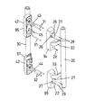
枠に受体を組付ける一例を示した分解斜視図である。It is the disassembled perspective view which showed an example which attaches a receiving body to a frame. 図6において、枠のネジ穴にネジを螺合して受体を枠に固定した状態を示した部分断面図である。In FIG. 6, it is the fragmentary sectional view which showed the state which screwed the screw | thread in the screw hole of the frame and fixed the receiving body to the frame. 既存のラッチ錠及び本締錠を錠箱に収納した本発明の実施例2の要部を断面した平面図である。It is the top view which carried out the cross section of the principal part of Example 2 of this invention which accommodated the existing latch lock and this lock in the lock box. 実施例2におけるプッシュ・プル式の扉錠の構成部分を扉に取り付ける場合の分解斜視図である。It is a disassembled perspective view in the case of attaching the component of the push-pull type door lock in Example 2 to a door. 一個のデッドボルトと一個のサムターンおよび一個のシリンダーとを備え、扉の開放端側から見た本発明の実施例3のプッシュ・プル式の扉錠の側面図である。It is a side view of the push-pull type door lock of Example 3 of this invention provided with one dead bolt, one thumb turn, and one cylinder, and it was seen from the open end side of the door. 図10の室内側ハンドルと室外側ハンドルとの分解斜視図である。FIG. 11 is an exploded perspective view of the indoor handle and the outdoor handle of FIG. 10. 枠に受孔を形成して受体を設けないようにした、図2に相当する本発明の実施例4の平面図である。It is a top view of Example 4 of this invention equivalent to FIG. 2 which formed the receiving hole in the frame so that the receiving body was not provided. 室内側ハンドルと室外側ハンドルの変形例を示す斜視図である。It is a perspective view showing a modification of an indoor side handle and an outdoor side handle.

室外側ハンドル30は、上部と下部に本締錠40操作用のシリンダー42を設けており、このシリンダー42に設けた鍵穴(図示せず)に合鍵を差し込み回動することにより、デットボルト41が錠箱1から出没するようにしてある。 The outdoor handle 30 is provided with cylinders 42 for operating the main locking 40 at the upper and lower portions. By inserting a key into a key hole (not shown) provided in the cylinder 42 and rotating, the dead bolt 41 is moved. It is designed to appear and disappear from the lock box 1.

そこで、実施例1におけるプッシュ・プル式の扉錠の取付方法の一例を、図4に基づいて以下に説明する。
なお、この実施例1のプッシュ・プル式の扉錠は、室外側から見て左吊元で外開きの扉aに取り付けているが、右吊元で外開きの扉aにも取り付けできるのは勿論であり、また各々内開きの扉にも取り付けできる。
Therefore, an example of a push-pull type door lock mounting method according to the first embodiment will be described below with reference to FIG.
Incidentally, the push-pull type Tobirajo of Example 1, but is attached to the door a of the outer opening at the left Tsumoto as viewed from the outdoor side, can be attached to the door a of the outer opening at the right hanging original Of course, it can also be attached to doors that open inward.

JP2009004140A 2009-01-10 2009-01-10 Push-pull door lock Active JP5390199B2 (en)

Priority Applications (1)

Application Number Priority Date Filing Date Title
JP2009004140A JP5390199B2 (en) 2009-01-10 2009-01-10 Push-pull door lock

Applications Claiming Priority (1)

Application Number Priority Date Filing Date Title
JP2009004140A JP5390199B2 (en) 2009-01-10 2009-01-10 Push-pull door lock

Publications (3)

Publication Number Publication Date
JP2010159613A JP2010159613A (en) 2010-07-22
JP2010159613A5 true JP2010159613A5 (en) 2012-02-16
JP5390199B2 JP5390199B2 (en) 2014-01-15

Family

ID=42576971

Family Applications (1)

Application Number Title Priority Date Filing Date
JP2009004140A Active JP5390199B2 (en) 2009-01-10 2009-01-10 Push-pull door lock

Country Status (1)

Country Link
JP (1) JP5390199B2 (en)

Families Citing this family (4)

* Cited by examiner, † Cited by third party
Publication number Priority date Publication date Assignee Title
JP5700628B2 (en) * 2010-09-27 2015-04-15 美和ロック株式会社 Imposition lock unit
JP5935250B2 (en) * 2011-07-13 2016-06-15 株式会社シブタニ Imposition push-pull lock and its mounting method
JP5886549B2 (en) * 2011-07-13 2016-03-16 株式会社ゴール Door lock
KR101642838B1 (en) 2014-07-31 2016-07-26 주식회사 밀다 Door Opening/closing Apparatus by Push, Pull or Turning on the Handle

Family Cites Families (4)

* Cited by examiner, † Cited by third party
Publication number Priority date Publication date Assignee Title
JPH03126978U (en) * 1990-04-02 1991-12-20
JPH0647538U (en) * 1992-10-12 1994-06-28 立山アルミニウム工業株式会社 Door handle
JP4159440B2 (en) * 2003-10-01 2008-10-01 株式会社ゴール Reversing latch lock
JP2005120769A (en) * 2003-10-20 2005-05-12 Miwa Lock Co Ltd Push pull lock for door

Similar Documents

Publication Publication Date Title
US7856857B2 (en) Door lock of key-driven transmission structure
JP2010159613A5 (en)
JP5390199B2 (en) Push-pull door lock
JP5937049B2 (en) Locking device
KR101277568B1 (en) Door handle
KR101246563B1 (en) Draw latch for door
JP2004052218A (en) Opening device
JP2008008035A (en) Sliding door sash
JP6633880B2 (en) Door device with electric lock
KR100948796B1 (en) Housing of Locking device for chassis door
JP6104023B2 (en) Joinery
KR100663700B1 (en) Lock apparatus for the furniture
JP5700628B2 (en) Imposition lock unit
JP5322306B2 (en) Sliding door locking device
JP2004211400A (en) Door lock
JP3209858U (en) Inner key using U-shaped door guard
CN106948686B (en) Manually operated door locking device
JP4585888B2 (en) Gate lock / door structure
JP2005307725A (en) Lock put into window frame
CN204492467U (en) For cabinet door and the safety cabinet of safety cabinet
CN201614780U (en) Vandalism lock assemble bolt
DK200800175U3 (en) Security lock t / door for locks and handles
TW202138661A (en) Door lock with which the locking operation can be performed without cooperating with other tools or screws during the assembly process thereby achieving convenient assembly
JP2012067542A5 (en)
RU116550U1 (en) CASTLE