JP2010152268A - Liquid crystal display device and projector - Google Patents
Liquid crystal display device and projector Download PDFInfo
- Publication number
- JP2010152268A JP2010152268A JP2008332977A JP2008332977A JP2010152268A JP 2010152268 A JP2010152268 A JP 2010152268A JP 2008332977 A JP2008332977 A JP 2008332977A JP 2008332977 A JP2008332977 A JP 2008332977A JP 2010152268 A JP2010152268 A JP 2010152268A
- Authority
- JP
- Japan
- Prior art keywords
- liquid crystal
- light
- display device
- optical axis
- crystal display
- Prior art date
- Legal status (The legal status is an assumption and is not a legal conclusion. Google has not performed a legal analysis and makes no representation as to the accuracy of the status listed.)
- Withdrawn
Links
Images


Classifications
-
- G—PHYSICS
- G02—OPTICS
- G02F—OPTICAL DEVICES OR ARRANGEMENTS FOR THE CONTROL OF LIGHT BY MODIFICATION OF THE OPTICAL PROPERTIES OF THE MEDIA OF THE ELEMENTS INVOLVED THEREIN; NON-LINEAR OPTICS; FREQUENCY-CHANGING OF LIGHT; OPTICAL LOGIC ELEMENTS; OPTICAL ANALOGUE/DIGITAL CONVERTERS
- G02F1/00—Devices or arrangements for the control of the intensity, colour, phase, polarisation or direction of light arriving from an independent light source, e.g. switching, gating or modulating; Non-linear optics
- G02F1/01—Devices or arrangements for the control of the intensity, colour, phase, polarisation or direction of light arriving from an independent light source, e.g. switching, gating or modulating; Non-linear optics for the control of the intensity, phase, polarisation or colour
- G02F1/13—Devices or arrangements for the control of the intensity, colour, phase, polarisation or direction of light arriving from an independent light source, e.g. switching, gating or modulating; Non-linear optics for the control of the intensity, phase, polarisation or colour based on liquid crystals, e.g. single liquid crystal display cells
- G02F1/133—Constructional arrangements; Operation of liquid crystal cells; Circuit arrangements
- G02F1/1333—Constructional arrangements; Manufacturing methods
- G02F1/1335—Structural association of cells with optical devices, e.g. polarisers or reflectors
- G02F1/13363—Birefringent elements, e.g. for optical compensation
-
- H—ELECTRICITY
- H04—ELECTRIC COMMUNICATION TECHNIQUE
- H04N—PICTORIAL COMMUNICATION, e.g. TELEVISION
- H04N9/00—Details of colour television systems
- H04N9/12—Picture reproducers
- H04N9/31—Projection devices for colour picture display, e.g. using electronic spatial light modulators [ESLM]
- H04N9/3102—Projection devices for colour picture display, e.g. using electronic spatial light modulators [ESLM] using two-dimensional electronic spatial light modulators
- H04N9/3105—Projection devices for colour picture display, e.g. using electronic spatial light modulators [ESLM] using two-dimensional electronic spatial light modulators for displaying all colours simultaneously, e.g. by using two or more electronic spatial light modulators
-
- G—PHYSICS
- G02—OPTICS
- G02F—OPTICAL DEVICES OR ARRANGEMENTS FOR THE CONTROL OF LIGHT BY MODIFICATION OF THE OPTICAL PROPERTIES OF THE MEDIA OF THE ELEMENTS INVOLVED THEREIN; NON-LINEAR OPTICS; FREQUENCY-CHANGING OF LIGHT; OPTICAL LOGIC ELEMENTS; OPTICAL ANALOGUE/DIGITAL CONVERTERS
- G02F1/00—Devices or arrangements for the control of the intensity, colour, phase, polarisation or direction of light arriving from an independent light source, e.g. switching, gating or modulating; Non-linear optics
- G02F1/01—Devices or arrangements for the control of the intensity, colour, phase, polarisation or direction of light arriving from an independent light source, e.g. switching, gating or modulating; Non-linear optics for the control of the intensity, phase, polarisation or colour
- G02F1/13—Devices or arrangements for the control of the intensity, colour, phase, polarisation or direction of light arriving from an independent light source, e.g. switching, gating or modulating; Non-linear optics for the control of the intensity, phase, polarisation or colour based on liquid crystals, e.g. single liquid crystal display cells
- G02F1/133—Constructional arrangements; Operation of liquid crystal cells; Circuit arrangements
- G02F1/1333—Constructional arrangements; Manufacturing methods
- G02F1/133308—Support structures for LCD panels, e.g. frames or bezels
- G02F1/133311—Environmental protection, e.g. against dust or humidity
-
- G—PHYSICS
- G02—OPTICS
- G02F—OPTICAL DEVICES OR ARRANGEMENTS FOR THE CONTROL OF LIGHT BY MODIFICATION OF THE OPTICAL PROPERTIES OF THE MEDIA OF THE ELEMENTS INVOLVED THEREIN; NON-LINEAR OPTICS; FREQUENCY-CHANGING OF LIGHT; OPTICAL LOGIC ELEMENTS; OPTICAL ANALOGUE/DIGITAL CONVERTERS
- G02F1/00—Devices or arrangements for the control of the intensity, colour, phase, polarisation or direction of light arriving from an independent light source, e.g. switching, gating or modulating; Non-linear optics
- G02F1/01—Devices or arrangements for the control of the intensity, colour, phase, polarisation or direction of light arriving from an independent light source, e.g. switching, gating or modulating; Non-linear optics for the control of the intensity, phase, polarisation or colour
- G02F1/13—Devices or arrangements for the control of the intensity, colour, phase, polarisation or direction of light arriving from an independent light source, e.g. switching, gating or modulating; Non-linear optics for the control of the intensity, phase, polarisation or colour based on liquid crystals, e.g. single liquid crystal display cells
- G02F1/133—Constructional arrangements; Operation of liquid crystal cells; Circuit arrangements
- G02F1/1333—Constructional arrangements; Manufacturing methods
- G02F1/1335—Structural association of cells with optical devices, e.g. polarisers or reflectors
- G02F1/133528—Polarisers
- G02F1/133531—Polarisers characterised by the arrangement of polariser or analyser axes
-
- G—PHYSICS
- G02—OPTICS
- G02F—OPTICAL DEVICES OR ARRANGEMENTS FOR THE CONTROL OF LIGHT BY MODIFICATION OF THE OPTICAL PROPERTIES OF THE MEDIA OF THE ELEMENTS INVOLVED THEREIN; NON-LINEAR OPTICS; FREQUENCY-CHANGING OF LIGHT; OPTICAL LOGIC ELEMENTS; OPTICAL ANALOGUE/DIGITAL CONVERTERS
- G02F1/00—Devices or arrangements for the control of the intensity, colour, phase, polarisation or direction of light arriving from an independent light source, e.g. switching, gating or modulating; Non-linear optics
- G02F1/01—Devices or arrangements for the control of the intensity, colour, phase, polarisation or direction of light arriving from an independent light source, e.g. switching, gating or modulating; Non-linear optics for the control of the intensity, phase, polarisation or colour
- G02F1/13—Devices or arrangements for the control of the intensity, colour, phase, polarisation or direction of light arriving from an independent light source, e.g. switching, gating or modulating; Non-linear optics for the control of the intensity, phase, polarisation or colour based on liquid crystals, e.g. single liquid crystal display cells
- G02F1/133—Constructional arrangements; Operation of liquid crystal cells; Circuit arrangements
- G02F1/1333—Constructional arrangements; Manufacturing methods
- G02F1/1335—Structural association of cells with optical devices, e.g. polarisers or reflectors
- G02F1/13363—Birefringent elements, e.g. for optical compensation
- G02F1/133635—Multifunctional compensators
-
- G—PHYSICS
- G02—OPTICS
- G02F—OPTICAL DEVICES OR ARRANGEMENTS FOR THE CONTROL OF LIGHT BY MODIFICATION OF THE OPTICAL PROPERTIES OF THE MEDIA OF THE ELEMENTS INVOLVED THEREIN; NON-LINEAR OPTICS; FREQUENCY-CHANGING OF LIGHT; OPTICAL LOGIC ELEMENTS; OPTICAL ANALOGUE/DIGITAL CONVERTERS
- G02F2202/00—Materials and properties
- G02F2202/40—Materials having a particular birefringence, retardation
-
- G—PHYSICS
- G02—OPTICS
- G02F—OPTICAL DEVICES OR ARRANGEMENTS FOR THE CONTROL OF LIGHT BY MODIFICATION OF THE OPTICAL PROPERTIES OF THE MEDIA OF THE ELEMENTS INVOLVED THEREIN; NON-LINEAR OPTICS; FREQUENCY-CHANGING OF LIGHT; OPTICAL LOGIC ELEMENTS; OPTICAL ANALOGUE/DIGITAL CONVERTERS
- G02F2413/00—Indexing scheme related to G02F1/13363, i.e. to birefringent elements, e.g. for optical compensation, characterised by the number, position, orientation or value of the compensation plates
- G02F2413/02—Number of plates being 2
Abstract
Description
本発明は、画像形成用の液晶表示装置、及び、かかる液晶表示装置を組み込んだプロジ
ェクターに関する。
The present invention relates to a liquid crystal display device for image formation and a projector incorporating such a liquid crystal display device.
プロジェクター等に組み込まれる液晶表示装置として、液晶パネルと入射偏光板と射出
偏光板とで構成されるものが存在する。このような液晶表示装置において、例えば光入射
側に配置される防塵ガラスと光射出側に配置される防塵ガラスとを水晶板からなるものと
し、水晶板の光学軸を入射面に垂直な方向に設定することが開示されている(特許文献1
参照)。同様に、光入射側に配置される防塵ガラスと光射出側に配置される防塵ガラスと
を水晶板からなるものとし、水晶板の光学軸(c軸)を送風ファンによる空気の流れ方向
に沿ったものとすることも開示されている(特許文献2参照)。
reference). Similarly, the dust-proof glass disposed on the light incident side and the dust-proof glass disposed on the light exit side are made of a crystal plate, and the optical axis (c-axis) of the crystal plate is along the air flow direction by the blower fan. It has also been disclosed (see Patent Document 2).
しかしながら、本願発明者による検討の結果、防塵ガラスを水晶板等の結晶材料に置き
換える場合、これに対向する偏光板との配置関係を考慮しなければ、表示画像のコントラ
ストが低下する場合があることが分かった。
However, as a result of the examination by the inventors of the present application, when replacing the dust-proof glass with a crystal material such as a quartz plate, the contrast of the display image may be lowered unless the arrangement relationship with the polarizing plate facing it is taken into consideration. I understood.
そこで、本発明は、防塵ガラスを水晶板等の結晶材料に置き換えた場合にも、表示画像
のコントラスト低下を抑えることができる液晶表示装置を提供することを目的とする。
Therefore, an object of the present invention is to provide a liquid crystal display device capable of suppressing a reduction in contrast of a display image even when the dustproof glass is replaced with a crystal material such as a quartz plate.
また、本発明は、上記のような液晶表示装置を組み込んだプロジェクターを提供するこ
とを目的とする。
Another object of the present invention is to provide a projector incorporating the liquid crystal display device as described above.
上記課題を解決するため、本発明に係る第1の液晶表示装置は、液晶デバイスと、液晶
デバイスの光入射側及び光射出側の少なくとも一方に配置される防塵板を有する液晶パネ
ルと、防塵板を挟んで液晶パネルに対向して配置される偏光フィルターと、を備える液晶
表示装置である。ここで、偏光フィルターの吸収軸の方向と防塵板の光学軸の方向とは直
交し、防塵板は、正の一軸性の結晶材料で形成され、システム光軸に垂直な2方向に関す
る屈折率差をΔnとし、システム光軸方向の厚みをdとし、使用する波長をλとしたとき
に、整数Nを用いて、以下の関係式
N≦Δnd/λ≦N+1/2 … (1)
を満たす。
In order to solve the above problems, a first liquid crystal display device according to the present invention includes a liquid crystal device, a liquid crystal panel having a dustproof plate disposed on at least one of a light incident side and a light emission side of the liquid crystal device, and a dustproof plate. And a polarizing filter disposed opposite to the liquid crystal panel with the electrode interposed therebetween. Here, the direction of the absorption axis of the polarizing filter and the direction of the optical axis of the dustproof plate are perpendicular to each other, and the dustproof plate is formed of a positive uniaxial crystal material and has a refractive index difference in two directions perpendicular to the system optical axis. Where Δn is the thickness in the system optical axis direction and d is the wavelength to be used, λ is the integer N, and the following relational expression N ≦ Δnd / λ ≦ N + 1/2 (1)
Meet.
上記液晶表示装置では、偏光フィルターの吸収軸の方向と正の一軸性の結晶材料で形成
された防塵板の光学軸の方向とが直交するので、システム光軸に平行な状態で入射する光
束は、偏光フィルターの通過に際して防塵板で複屈折作用を受けない。よって、正の一軸
性の結晶材料で形成された防塵板によって冷却効率を高めつつ、防塵板の屈折率異方性に
よって変調量がずれた変調光が射出される現象を抑えることができる。さらに、上記液晶
表示装置において、システム光軸に対して傾斜した状態で入射する光束は、防塵板の通過
に際して防塵板で複屈折作用を受けても、このような複屈折作用が液晶パネルで生じる複
屈折作用と相殺されると考えられる。よって、システム光軸に対して傾いた光束に対して
液晶パネルの視野角補償効果を有する変調光を得ることができるので、コントラスト比に
関する視野角特性が良好な液晶表示装置を提供することができる。
In the above liquid crystal display device, the direction of the absorption axis of the polarizing filter and the direction of the optical axis of the dustproof plate made of a positive uniaxial crystal material are orthogonal to each other. When passing through the polarizing filter, the dustproof plate does not receive birefringence. Therefore, it is possible to suppress the phenomenon in which the modulated light whose modulation amount is shifted due to the refractive index anisotropy of the dustproof plate is emitted while the cooling efficiency is improved by the dustproof plate formed of the positive uniaxial crystal material. Further, in the above liquid crystal display device, even if the light beam incident in a state inclined with respect to the system optical axis is subjected to a birefringence action at the dustproof plate when passing through the dustproof plate, such a birefringence effect occurs in the liquid crystal panel. It is thought that this cancels out the birefringence effect. Therefore, it is possible to obtain modulated light having a viewing angle compensation effect of the liquid crystal panel with respect to a light beam tilted with respect to the system optical axis, and thus it is possible to provide a liquid crystal display device with favorable viewing angle characteristics regarding the contrast ratio. .
本発明に係る第2の液晶表示装置は、液晶デバイスと、液晶デバイスの光入射側及び光
射出側の少なくとも一方に配置される防塵板を有する液晶パネルと、防塵板を挟んで液晶
パネルに対向して配置される偏光フィルターと、を備える液晶表示装置である。ここで、
偏光フィルターの吸収軸の方向と防塵板の光学軸の方向とは直交し、防塵板は、負の一軸
性の結晶材料で形成され、システム光軸に垂直な2方向に関する屈折率差をΔnとし、シ
ステム光軸方向の厚みをdとし、使用する波長をλとしたときに、整数Nを用いて、以下
の関係式
N≦Δnd/λ≦N−1/2 … (2)
を満たす。
A second liquid crystal display device according to the present invention is a liquid crystal device, a liquid crystal panel having a dustproof plate disposed on at least one of a light incident side and a light emission side of the liquid crystal device, and facing the liquid crystal panel across the dustproof plate. And a polarizing filter disposed in a liquid crystal display device. here,
The direction of the absorption axis of the polarizing filter and the direction of the optical axis of the dustproof plate are perpendicular to each other. The dustproof plate is made of a negative uniaxial crystal material, and the refractive index difference in two directions perpendicular to the system optical axis is Δn. When the thickness in the system optical axis direction is d and the wavelength to be used is λ, the integer N is used, and the following relational expression N ≦ Δnd / λ ≦ N−1 / 2 (2)
Meet.
上記液晶表示装置では、偏光フィルターの吸収軸の方向と負の一軸性の結晶材料で形成
された防塵板の光学軸の方向とが直交するので、システム光軸に平行な状態で入射する光
束は、偏光フィルターの通過に際して防塵板で複屈折作用を受けない。よって、負の一軸
性の結晶材料で形成された防塵板によって冷却効率を高めつつ、防塵板の屈折率異方性に
よって変調量がずれた変調光が射出される現象を抑えることができる。さらに、上記液晶
表示装置において、システム光軸に対して傾斜した状態で入射する光束は、防塵板の通過
に際して防塵板で複屈折作用を受けても、このような複屈折作用が液晶パネルで生じる複
屈折作用と相殺されると考えられる。よって、システム光軸に対して傾いた光束に対して
液晶パネルの視野角補償効果を有する変調光を得ることができるので、コントラスト比に
関する視野角特性が良好な液晶表示装置を提供することができる。
In the above liquid crystal display device, the direction of the absorption axis of the polarizing filter and the direction of the optical axis of the dustproof plate made of a negative uniaxial crystal material are perpendicular to each other. When passing through the polarizing filter, the dustproof plate does not receive birefringence. Therefore, it is possible to suppress the phenomenon in which the modulated light whose modulation amount is shifted due to the refractive index anisotropy of the dustproof plate is emitted while the cooling efficiency is improved by the dustproof plate formed of the negative uniaxial crystal material. Further, in the above liquid crystal display device, even if the light beam incident in a state inclined with respect to the system optical axis is subjected to a birefringence action at the dustproof plate when passing through the dustproof plate, such a birefringence effect occurs in the liquid crystal panel. It is thought that this cancels out the birefringence effect. Therefore, it is possible to obtain modulated light having a viewing angle compensation effect of the liquid crystal panel with respect to a light beam tilted with respect to the system optical axis, and thus it is possible to provide a liquid crystal display device with favorable viewing angle characteristics regarding the contrast ratio. .
また、本発明の具体的な態様又は側面によれば、上記液晶表示装置において、防塵板が
、水晶及びサファイアのいずれか一方である。この場合、防塵板による光量損失を抑えつ
つ液晶デバイスを確実に冷却することができる。
According to a specific aspect or aspect of the present invention, in the liquid crystal display device, the dustproof plate is either one of crystal and sapphire. In this case, it is possible to reliably cool the liquid crystal device while suppressing loss of light amount due to the dustproof plate.
また、本発明の別の態様では、液晶デバイスが、液晶を挟持する一対の基板と、一対の
基板のうち一方の基板上に形成される表示用電極とを有する。
In another embodiment of the present invention, the liquid crystal device includes a pair of substrates that sandwich the liquid crystal and a display electrode formed on one of the pair of substrates.
また、本発明のさらに別の態様では、液晶パネルを挟んで偏光フィルターの反対側に配
置される偏光フィルターをさらに備える。この場合、液晶パネルは、透過型の光変調装置
であり、光入射側の偏光フィルターによって、液晶パネルに入射する照明光の偏光方向が
調整されるとともに、光射出側の偏光フィルターによって、液晶パネルから射出される光
から所定の偏光方向の変調光が取り出される。
In still another aspect of the present invention, a polarizing filter is further provided on the opposite side of the polarizing filter with the liquid crystal panel interposed therebetween. In this case, the liquid crystal panel is a transmissive light modulator, and the polarization direction of the illumination light incident on the liquid crystal panel is adjusted by the light incident side polarization filter, and the light emission side polarization filter adjusts the liquid crystal panel. The modulated light having a predetermined polarization direction is extracted from the light emitted from.
上記課題を解決するため、本発明に係るプロジェクターは、照明用の光束を射出する照
明装置と、照明装置から射出された光束から複数の色光を分離して、複数の色光を各色の
光路にそれぞれ導く色分離光学系と、各色の光路上に配置される上述の液晶表示装置を有
し、複数の色光を画像情報に応じて変調する光変調部と、各色の光路上に配置される各色
の液晶表示装置からの各色の変調光を合成して射出する光合成光学系と、光合成光学系を
経て合成された変調光を投射する投射光学系とを備える。
In order to solve the above problems, a projector according to the present invention includes a lighting device that emits a light beam for illumination, and a plurality of color lights separated from the light beam emitted from the lighting device, and the plurality of color lights are respectively transmitted to the light paths of the respective colors. A color separation optical system for guiding, and the above-described liquid crystal display device arranged on the optical path of each color, a light modulation unit that modulates a plurality of color lights according to image information, and each color arranged on the optical path of each color A light combining optical system that combines and emits modulated light of each color from the liquid crystal display device, and a projection optical system that projects the modulated light combined through the light combining optical system.
上記プロジェクターでは、上述した本願の液晶表示装置を有する光変調部を備えており
、液晶表示装置の温度上昇を抑えつつコントラスト比についての視野角特性を良好なもの
とできるので、高品位の画像を投射することができる。
The projector includes a light modulation unit having the above-described liquid crystal display device of the present application, and can improve the viewing angle characteristics with respect to the contrast ratio while suppressing the temperature rise of the liquid crystal display device. Can project.
また、本発明の具体的な態様によれば、上記プロジェクターにおいて、照明装置が、偏
光方向を所定方向に揃えた照明光を射出し、各色の液晶表示装置が、偏光方向が共通の色
光を変調し、光合成光学系が、システム光軸を通ってシステム光軸に垂直な軸のまわりに
傾斜した少なくとも1つのダイクロイックミラーを有し、各色の像光を少なくとも1つの
ダイクロイックミラーの波長特性を利用して合成する。そして、光変調部が、各色の液晶
表示装置として、上記少なくとも1つのダイクロイックミラーで反射される変調光を射出
する第1タイプの液晶表示装置と、上記少なくとも1つのダイクロイックミラーを透過さ
せる変調光を射出する第2タイプの液晶表示装置とを有し、第1タイプの液晶表示装置と
第2タイプの液晶表示装置とのいずれか一方と、光合成光学系との間に、偏光方向を90
°切り換える波長板を有する。この場合、各色の液晶表示装置に入射させる偏光を揃える
ことで、すべての光路で偏光フィルター、防塵板等の特性の共通化を図ることができると
ともに、特定色の光路に選択的に配置される波長板によってダイクロイックミラーを利用
した変調光の合成を効率的なものとできる。
Further, according to a specific aspect of the present invention, in the projector, the illumination device emits illumination light whose polarization direction is aligned in a predetermined direction, and the liquid crystal display devices of each color modulate color light having a common polarization direction. However, the light combining optical system has at least one dichroic mirror inclined through an optical axis through the system optical axis and perpendicular to the system optical axis, and uses the wavelength characteristics of at least one dichroic mirror for image light of each color. To synthesize. Then, the light modulation unit, as the liquid crystal display device of each color, the first type liquid crystal display device that emits the modulated light reflected by the at least one dichroic mirror, and the modulated light that transmits the at least one dichroic mirror. A second-type liquid crystal display device that emits light, and a polarization direction of 90 is set between one of the first-type liquid crystal display device and the second-type liquid crystal display device and the photosynthesis optical system.
° Has a wave plate to switch. In this case, by aligning the polarized light incident on the liquid crystal display device of each color, it is possible to share the characteristics of the polarizing filter, the dustproof plate, etc. in all the optical paths, and selectively arrange the optical paths of the specific colors. The wave plate enables efficient synthesis of modulated light using a dichroic mirror.
〔第1実施形態〕
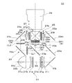
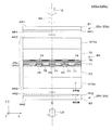
図1は、本発明に係る第1実施形態の液晶表示装置を組み込んだプロジェクターの光学
系の構成を説明する概念図である。
[First Embodiment]
FIG. 1 is a conceptual diagram illustrating the configuration of an optical system of a projector incorporating the liquid crystal display device according to the first embodiment of the invention.
本プロジェクター10は、光源光を発生する光源装置21と、光源装置21からの光源
光を青緑赤の3色に分離する色分離光学系23と、色分離光学系23から射出された各色
の照明光によって照明される光変調部25と、光変調部25から射出された各色の像光を
合成するクロスダイクロイックプリズム27と、クロスダイクロイックプリズム27を経
た像光をスクリーン(不図示)に投射する投射レンズ29とを備える。
The
以上のプロジェクター10において、光源装置21は、光源ランプ21aと、凹レンズ
21bと、一対のレンズアレイ21d,21eと、偏光変換部材21gと、重畳レンズ2
1iとを備える。このうち、光源ランプ21aは、例えば高圧水銀ランプ等であるランプ
本体22aと、光源光を回収して前方に射出させる凹面鏡22bとを備える。凹レンズ2
1bは、光源ランプ21aからの光源光を平行化する役割を有するが、例えば凹面鏡22
bが放物面鏡である場合には、省略することもできる。一対のレンズアレイ21d,21
eは、マトリクス状に配置された複数の要素レンズからなり、これらの要素レンズによっ
て凹レンズ21bを経た光源ランプ21aからの光源光を分割して個別に集光・発散させ
る。偏光変換部材21gは、詳細は省略するが、PBS及びミラーを組み込んだプリズム
アレイと、当該プリズムアレイに設けた射出面上にストライプ状に貼り付けられる波長板
アレイとを備える。この偏光変換部材21gは、レンズアレイ21eから射出した光源光
を例えば図1の紙面に水平(より具体的には、後述するクロスダイクロイックプリズム2
7の第1ダイクロミラー27aと第2ダイクロミラー27bの交線に垂直)な第1偏光方
向の直線偏光のみに変換して次段光学系に供給する。重畳レンズ21iは、偏光変換部材
21gを経た照明光を全体として適宜収束させることにより、光変調部25に設けた各色
の液晶ライトバルブ25a,25b,25cに対する重畳照明を可能にする。つまり、両
レンズアレイ21d,21eと重畳レンズ21iとを経た照明光は、以下に詳述する色分
離光学系23を通って、光変調部25に設けられた各色の液晶パネル26a,26b,2
6cを均一に重畳照明する。
In the
1i. Among these, the
1b has the role of collimating the light source light from the
If b is a parabolic mirror, it can be omitted. A pair of
e is composed of a plurality of element lenses arranged in a matrix, and these element lenses divide the light source light from the
The first
6c is uniformly superimposed and illuminated.
色分離光学系23は、第1及び第2ダイクロイックミラー23a,23bと、フィール
ドレンズ23f,23g,23hと、反射ミラー23j,23m,23n,23oとを備
え、光源装置21とともに照明装置を構成する。ここで、第1ダイクロイックミラー23
aは、青緑赤の3色のうち例えば青(B)色を透過させ、緑(G)及び赤(R)色を反射
する。また、第2ダイクロイックミラー23bは、入射した緑赤の2色のうち例えば緑(
G)色を反射し、赤(R)色を透過させる。これにより、光源光を構成するB光、G光、
及びR光は、第1、第2、及び第3光路OP1,OP2,OP3にそれぞれ導かれ、異な
る照明対象にそれぞれ入射する。具体的に説明すると、光源装置21からの光源光は、反
射ミラー23jで光路を折り曲げられて第1ダイクロイックミラー23aに入射する。こ
の第1ダイクロイックミラー23aを通過したB光は、反射ミラー23mを経て、液晶ラ
イトバルブ25aに対向するフィールドレンズ23fに入射する。また、第1ダイクロイ
ックミラー23aで反射されて第2ダイクロイックミラー23bでさらに反射されたG光
は、液晶ライトバルブ25bに対向するフィールドレンズ23gに入射する。さらに、第
2ダイクロイックミラー23bを通過したR光は、レンズLL1,LL2及び反射ミラー
23n,23oを経て、液晶ライトバルブ25cに対向するフィールドレンズ23hに入
射する。なお、各フィールドレンズ23f,23g,23hは、各液晶ライトバルブ25
a,25b,25cに入射する照明光の入射角度を調節する機能を有する。レンズLL1
,LL2及びフィールドレンズ23hは、リレー光学系を構成している。このリレー光学
系は、第1レンズLL1の像を、第2レンズLL2を介してほぼそのままフィールドレン
ズ23hに伝達する機能を有する。
The color separation
a transmits, for example, the blue (B) color among the three colors of blue, green, and red, and reflects the green (G) and red (R) colors. In addition, the second
G) Reflects color and transmits red (R) color. As a result, the B light, G light constituting the light source light,
And R light are respectively guided to the first, second, and third optical paths OP1, OP2, and OP3, and are incident on different illumination targets. More specifically, the light source light from the
It has a function of adjusting the incident angle of illumination light incident on a, 25b, and 25c. Lens LL1
, LL2 and the
光変調部25は、上記した各色用の3つの光路OP1,OP2,OP3に対応して、3
つの液晶ライトバルブ25a,25b,25cを備える。各液晶ライトバルブ25a,2
5b,25cは、入射した照明光の強度の空間分布を変調する非発光型の光変調装置であ
る。
The
Two liquid
ここで、第1光路OP1に配置されたB色用の液晶ライトバルブ25aは、液晶表示装
置を具体化したものであり、B光によって照明される液晶パネル26aと、液晶パネル2
6aの入射側に配置される偏光フィルター25eと、液晶パネル26aの射出側に配置さ
れる偏光フィルター25hとを備える。この液晶ライトバルブ25aは、色分離光学系2
3に設けたフィールドレンズ23fの後段に配置されており、第1ダイクロイックミラー
23aを透過したB光によって均一に照明される。液晶ライトバルブ25aにおいて、偏
光フィルター25eは、入射したB光について、紙面に平行な第1偏光方向の直線偏光を
選択的に透過させて液晶パネル26aに導く。ここで、第1偏光方向は、上述のようにク
ロスダイクロイックプリズム27の第1ダイクロミラー27aと第2ダイクロミラー27
bとの交線に垂直な方向(後述するX軸方向)を意味する。液晶パネル26aは、これに
入射した第1偏光方向の直線偏光を画像信号に応じて例えば部分的に紙面に垂直な第2偏
光方向の直線偏光に変換する。ここで、第2偏光方向は、クロスダイクロイックプリズム
27の第1ダイクロミラー27aと第2ダイクロミラー27bとの交線に平行な方向(後
述するY軸方向)を意味する。偏光フィルター25hは、液晶パネル26aを経て変調さ
れた第2偏光方向の直線偏光のみを選択的に透過させる。
Here, the B color liquid crystal
A
3 is arranged at the rear stage of the
It means the direction perpendicular to the line of intersection with b (X-axis direction to be described later). The
第2光路OP2に配置されたG色用の液晶ライトバルブ25bは、液晶表示装置を具体
化したものであり、G光によって照明される液晶パネル26bと、液晶パネル26bの入
射側に配置される偏光フィルター25fと、液晶パネル26aの射出側に配置される偏光
フィルター25iと、1/2波長板25pとを備える。この液晶ライトバルブ25bは、
色分離光学系23に設けたフィールドレンズ23gの後段に配置されており、第2ダイク
ロイックミラー23bで反射されたG光によって均一に照明される。液晶ライトバルブ2
5bにおいて、偏光フィルター25fは、入射したG光について、紙面に平行な第1偏光
方向の直線偏光を選択的に透過させて液晶パネル26bに導く。液晶パネル26bは、こ
れに入射した第1偏光方向の直線偏光を画像信号に応じて例えば部分的に紙面に垂直な第
2偏光方向の直線偏光に変換する。偏光フィルター25iは、液晶パネル26bを経て変
調された第2偏光方向の直線偏光のみを選択的に透過させる。1/2波長板25pは、偏
光フィルター25iを透過した第2偏光方向の直線偏光の偏光方向を90°回転させて紙
面に平行な第1偏光方向の直線偏光に切り換える。
The liquid crystal
It is arranged at the rear stage of the
In 5b, the
第3光路OP3に配置されたR色用の液晶ライトバルブ25cは、液晶表示装置を具体
化したものであり、R光によって照明される液晶パネル26cと、液晶パネル26cの入
射側に配置される偏光フィルター25gと、液晶パネル26aの射出側に配置される偏光
フィルター25jとを備える。この液晶ライトバルブ25cは、色分離光学系23に設け
たフィールドレンズ23hの後段に配置されており、第2ダイクロイックミラー23bを
透過したR光によって均一に照明される。液晶ライトバルブ25cにおいて、偏光フィル
ター25gは、入射したR光について、紙面に平行な第1偏光方向の直線偏光を選択的に
透過させて液晶パネル26cに導く。液晶パネル26cは、これに入射した第1偏光方向
の直線偏光を画像信号に応じて例えば部分的に紙面に垂直な第2偏光方向の直線偏光に変
換する。偏光フィルター25jは、液晶パネル26cを経て変調された第2偏光方向の直
線偏光のみを選択的に透過させる。
The liquid crystal
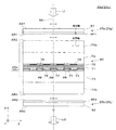
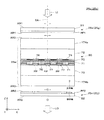
図2は、図1に示すプロジェクター10の光変調部25を構成するB光用の液晶ライト
バルブ25aの構造を説明する拡大断面図である。なお、図2において、Z軸方向は、シ
ステム光軸SAが延びる方向に対応する。また、X軸方向は、クロスダイクロイックプリ
ズム27中の第1及び第2ダイクロミラー27a,27bの交線に垂直な方向に相当し、
Y軸方向は、第1及び第2ダイクロミラー27a,27bの交線に平行な方向に相当する
ものとする。
FIG. 2 is an enlarged cross-sectional view illustrating the structure of the liquid crystal
The Y-axis direction corresponds to a direction parallel to the intersection line of the first and second
液晶ライトバルブ25aにおいて、入射側に設けた偏光フィルター25eは、基板S1
上に樹脂製の第1偏光フィルムPF1を接着したものであり、入出射面の法線がそれぞれ
システム光軸SAすなわちZ軸に平行になっている。偏光フィルター25eは、偏光素子
としての第1偏光フィルムPF1によって、X方向に沿った第1偏光方向のP偏光のみを
通過させる。つまり、偏光フィルター25eの吸収軸はY方向に延びている。ここで、第
1偏光フィルムPF1を支持する基板S1は、例えば石英ガラス製であり、X方向に沿っ
た第1偏光方向のP偏光をそのままシステム光軸SAに沿って射出させる。なお、偏光フ
ィルター25eの入射面と射出面とには、反射防止膜AR1が設けられており、迷光の発
生を防止している。
In the liquid crystal
The first polarizing film PF1 made of resin is bonded to the upper surface, and the normal lines of the incident and outgoing surfaces are parallel to the system optical axis SA, that is, the Z axis. The
一方、射出側に設けた偏光フィルター25hは、基板S2上に樹脂製の第2偏光フィル
ムPF2を接着したものであり、入出射面の法線がそれぞれシステム光軸SAすなわちZ
軸に平行になっている。偏光フィルター25hは、偏光素子としての第2偏光フィルムP
F2によってY方向に沿った第2偏光方向のS偏光のみを通過させ、P偏光(非変調光)
を吸収等により排除する。つまり、偏光フィルター25hの吸収軸はX方向に延びている
。ここで、第2偏光フィルムPF2を支持する基板S2は、例えば石英ガラス製であり、
Y方向に沿った第2偏光方向のS偏光をそのままシステム光軸SAに沿って射出させる。
なお、偏光フィルター25hの入射面と射出面とには、反射防止膜AR2が設けられてお
り、迷光の発生を防止している。
On the other hand, the
It is parallel to the axis. The
F2 allows only S-polarized light in the second polarization direction along the Y direction to pass, and P-polarized light (unmodulated light)
Are eliminated by absorption or the like. That is, the absorption axis of the
The S-polarized light in the second polarization direction along the Y direction is emitted as it is along the system optical axis SA.
An antireflection film AR2 is provided on the incident surface and the exit surface of the
以上では、第2偏光フィルムPF2の支持用の基板S2を石英ガラス製としたが、水晶
製とすることにより、第1偏光フィルムPF1よりも比較的加熱されやすい状態にある第
2偏光フィルムPF2を効率良く冷却することができる。
In the above description, the substrate S2 for supporting the second polarizing film PF2 is made of quartz glass. However, by making the substrate S2 made of quartz, the second polarizing film PF2 that is relatively easily heated than the first polarizing film PF1 is used. It can be cooled efficiently.
以上の説明から明らかなように、偏光フィルター25eを構成する第1偏光フィルムP
F1と、偏光フィルター25hを構成する第2偏光フィルムPF2とは、クロスニコルを
構成するように配置されている。これら第1及び第2偏光フィルムPF1,PF2の間に
挟まれた液晶パネル26aは、第1偏光フィルムPF1側から入射した入射光LIを入力
信号に応じて画素単位で部分的にP偏光からS偏光に変化させ、変化後の変調光を射出光
LOとして第2偏光フィルムPF2側に射出する。このように、液晶ライトバルブ25a
から射出される変調光は、後述するクロスダイクロイックプリズム27での光合成に適す
るS偏光状態の射出光LOとなっている。
As is clear from the above description, the first polarizing film P constituting the
F1 and the second polarizing film PF2 constituting the
The modulated light emitted from the light is S-polarized emitted light LO suitable for photosynthesis at a cross
両偏光フィルター25e,25h間の液晶パネル26aは、垂直配向モードで動作する
液晶(すなわち垂直配向型の液晶)で構成される液晶層71を挟んで、入射側に第1基板
72と、射出側に第2基板73とを備える。これらの基板72,73は、ともに平板状で
あり、偏光フィルター25e等と同様に、入出射面の法線がシステム光軸SAすなわちZ
軸に平行になるように配置されている。第1基板72の外側には、光透過性の入射側防塵
板74aが貼り付けられており、第2基板73の外側には、光透過性の射出側防塵板74
bが貼り付けられている。これらの防塵板74a,74bは、ともに平板状であり、偏光
フィルター25e等と同様に、入出射面の法線がシステム光軸SAすなわちZ軸に平行に
なるように配置されている。この液晶パネル26aの入射側防塵板74a側の入射面と、
射出側防塵板74b側の射出面とには、反射防止膜AR3が設けられており、迷光の発生
を防止している。
A
It is arranged to be parallel to the axis. A light transmissive incident side
b is pasted. These
An antireflection film AR3 is provided on the exit surface on the exit side dustproof
入射側防塵板74aは、正の一軸性の結晶材料、具体的には水晶製の平板であり、射出
側防塵板74bは、等方性の無機材料、具体的には石英ガラス製の平板である。入射側防
塵板74aは、これを形成する水晶の光学軸がX軸方向に延びるように切り出されたもの
である。つまり、入射側防塵板74aの光学軸は、偏光フィルター25eの吸収軸に対し
て垂直な状態になっている。
The incident-
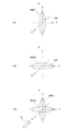
図3は、入射側防塵板74aの機能を説明する図である。図3(A)に示すように、入
射側防塵板74aを構成する水晶は、X方向に延びる光学軸OAの方向に関する屈折率が
相対的に大きな正の一軸性の屈折率楕円体RIE1に対応する光学的異方性を有する。具
体的な大小関係で説明すると、図中の各方位XYZに関する屈折率をNX,NY,NZと
して、NY=NZ<NXなる関係が成り立つ。一方、偏光フィルター25eの第1偏光フ
ィルムPF1は、例えば染料を吸着させて染色したPVA(ポリビニールアルコール)を
TAC(トリアセチルセルロース)上に貼り付けた延伸フィルムであり、その延伸方向に
吸収係数を持たせている。第1偏光フィルムPF1が吸収係数を有するということは、屈
折率に虚数部分が存在するが(NX=NZ=n,NY=n+in'、ここでn,n'は屈折
率であり、透過軸方向は100%光が透過する理想的な場合を考える)、入射側防塵板7
4aと同様に屈折率楕円体として扱うことができることを意味するので、第1偏光フィル
ムPF1すなわち偏光フィルター25eは、例えば図3(B)に示すような正の一軸性の
屈折率楕円体RIE2と同様に振る舞う。よって、液晶ライトバルブ25aに入射する入
射光LIを考えた場合、この入射光LIがシステム光軸SAすなわちZ軸に平行であれば
、図3(C)に示すように、偏光フィルター25eと入射側防塵板74aとを合成しても
、X軸方向やY軸方向に沿った光学軸が見かけ上維持される。つまり、入射側防塵板74
aが入射光LIの位相状態に作用を及ぼして偏光方向を変化させるといったことは起こら
ず、同様に偏光フィルター25eが偏光方向を変化させるといったことも起こらない。し
かしながら、液晶ライトバルブ25aに入射する入射光LIは、システム光軸SAすなわ
ちZ軸に対して傾いて入射する成分を有し、このような斜入射成分にとって、偏光フィル
ター25eの屈折率楕円体RIE2の光学軸OAと、入射側防塵板74aの屈折率楕円体
RIE1の光学軸OAとは、見かけ上90°に維持されなくなる。よって、斜入射成分に
関しては、入射側防塵板74aや偏光フィルター25eが入射光LIの位相状態に作用を
及ぼして偏光方向を変化させる。ここで、入射光LIのうち斜入射成分は、コントラスト
比の視野角特性に影響するので、入射側防塵板74aや偏光フィルター25eによる位相
作用が液晶ライトバルブ25aの視野角特性を補償することが望ましい。このため、本実
施形態では、入射側防塵板74aのシステム光軸SAに垂直な2方向に関する屈折率差を
Δn(=|NX−NY|)とし、システム光軸SA方向の厚みをdとし、使用されるB色
の波長をλとしたときに、以下の関係式
N≦Δnd/λ≦N+1/2 … (1)
(ここで、Nは整数)
を満たすようにしている。つまり、入射側防塵板74aの光学軸OA方向の位相ずれが半
波長分以下となるようにすることで、詳細は後述するが、入射側防塵板74aの屈折率異
方性によって変調量がずれた変調光が液晶ライトバルブ25aから射出される現象を抑え
ることができることを実験的に確認した。
FIG. 3 is a diagram illustrating the function of the incident-
4a, the first polarizing film PF1, that is, the
It does not occur that a affects the phase state of the incident light LI to change the polarization direction, and similarly, the
(Where N is an integer)
To meet. That is, by making the phase shift in the optical axis OA direction of the incident side dustproof
図2に戻って、液晶パネル26aにおいて、第1基板72の液晶層71側の面上には、
透明な共通電極75が設けられており、その上には、例えば配向膜76が形成されている
。一方、第2基板73の液晶層71側の面上には、マトリクス状に配置された表示用電極
としての複数の透明画素電極77と、各透明画素電極77に電気的に接続可能な配線(不
図示)と、透明画素電極77及び配線の間に介在する薄膜トランジスタ(不図示)とが設
けられており、その上には、例えば配向膜78が形成されている。ここで、第1及び第2
基板72,73と、これらに挟まれた液晶層71と、電極75,77とは、光能動素子、
すなわち入射光LIの偏光状態を入力信号に応じて変調するための液晶デバイス80とし
て機能する部分である。この液晶デバイス80を構成する各画素部分PPは、1つの透明
画素電極77と、共通電極75の一部と、両配向膜76,78の一部と、液晶層71の一
部とを含む。なお、第1基板72と共通電極75との間には、各画素部分PPを区分する
ように格子状のブラックマトリクス79が設けられている。
Returning to FIG. 2, in the
A transparent
The
That is, it is a portion that functions as a
以上の液晶デバイス80において、配向膜76,78は、電界の存在しない状態で、液
晶層71を構成する液晶性化合物をシステム光軸SAすなわちZ軸に略平行な状態に配列
させる役割を有する。ただし、Z軸に沿った方向に適度な電界を形成した場合、液晶層7
1を構成する液晶性化合物は、システム光軸SAすなわちZ軸に略平行な状態から例えば
XY面内の所定方位に向けて傾けられる。これにより、一対の偏光フィルムPF1,PF
2の間に挟まれた液晶層71をノーマリブラックモードで動作させることになり、電圧非
印加のオフ状態で最大遮光状態(光オフ状態)を確保することができる。つまり、液晶パ
ネル26aは、光オフ状態の黒表示時に、P偏光をそのまま変化させないで通過させる。
また、液晶パネル26aは、光オン状態の白表示時に、P偏光をS偏光に切替えて通過さ
せる。
In the
The liquid crystal compound constituting 1 is tilted from a state substantially parallel to the system optical axis SA, that is, the Z axis, for example, toward a predetermined direction in the XY plane. Thereby, a pair of polarizing films PF1, PF
The
Further, the
以上では、図2等に基づいてB光用の液晶ライトバルブ25aの構造及び機能を説明し
たが、R光用の液晶ライトバルブ25cも、B光用の液晶ライトバルブ25aと同様の構
造及び機能を有する。つまり、図2等に示すように、偏光フィルター25gのうち第1偏
光フィルムPF1によって、P偏光のみを選択的に透過させ、液晶パネル26cの変調に
よってP偏光からS偏光に変化させ、偏光フィルター25jによって、液晶ライトバルブ
25cから射出される変調光をS偏光状態の射出光LOとすることができる。
In the above, the structure and function of the liquid crystal
G光用の液晶ライトバルブ25bは、図4に示すように、B光用の液晶ライトバルブ2
5a等と基本的に同様の構造及び機能を有するが、光射出側に、1/2波長板25pを追
加した点が異なっている。これにより、偏光フィルター25fのうち第1偏光フィルムP
F1によって、P偏光のみを選択的に透過させ、液晶パネル26bの変調によってP偏光
からS偏光に変化させる。さらに、偏光フィルター25iによって、S偏光状態の変調光
のみを透過させ、1/2波長板25pによって、液晶ライトバルブ25bから射出される
変調光をP偏光状態の射出光LOとすることができる。
The liquid crystal
The structure and function are basically the same as those of 5a and the like, except that a half-
F1 selectively transmits only P-polarized light, and changes from P-polarized light to S-polarized light by modulation of the
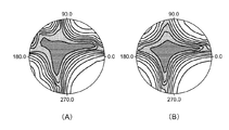
図5(A)は、本実施形態の液晶ライトバルブ25aのコントラスト比の視野角特性を
説明する図である。なお、この例では、入射側防塵板74aを形成する水晶板の厚みtを
1.1mmとしている。図において、中心からの方位及び距離が視野角の方向及び角度を
示し、コントラスト比の等高線によって視野角特性を表している。図5(A)からも明ら
かなように、本実施形態の液晶ライトバルブ25aの場合、比較的広い視野角範囲でコン
トラスト比が比較的高くなっている。図5(B)は、比較例の液晶ライトバルブのコント
ラスト比の視野角特性を説明する図である。比較例の液晶ライトバルブは、液晶ライトバ
ルブ25a等と基本的に同様の構造を有するが、入射側防塵板74aの光学軸が、偏光フ
ィルター25eの吸収軸に対して平行に配置されている。つまり、比較例の入射側防塵板
74aの光学軸はY軸方向に延びている。比較例の場合、コントラスト比の高い範囲が多
少狭くなっている。
FIG. 5A is a diagram illustrating the viewing angle characteristics of the contrast ratio of the liquid crystal
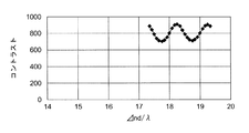
図6は、液晶ライトバルブ25a中において入射側防塵板74aの厚みを変化させた場
合のコントラスト比の変化を説明するグラフである。なお、この例では、入射側防塵板7
4aを形成する水晶板の厚みtの調整範囲を1040〜1160μmとした。グラフから
も明らかなように、入射側防塵板74aの厚みを変化させることにより、コントラスト比
が平均値800を中心として正弦的な変化で増減することがわかる。この場合の変化の周
期は、Δnd/λであり、N〜N+1/2の範囲内にピークが存在し、この範囲でコント
ラスト比が相対的に向上することがわかる。つまり、以下の関係式
N≦Δnd/λ≦N+1/2 … (1)
を満たすように、入射側防塵板74aの屈折率差Δnや厚みdを調整することで、入射側
防塵板で生じる位相差が液晶ライトバルブ25aで生じる位相差を打ち消す特性を持たせ
ることができる。これにより液晶ライトバルブ25aの視野角特性が補償され、コントラ
ストが向上する。ここで、入射側防塵板74aの働きについて考察すると、本実施形態の
ように、入射側防塵板74aの光学軸が偏光フィルター25eの吸収軸に対して垂直な状
態になっている場合、入射側防塵板74a及び偏光フィルター25eを一組とする複合光
学素子は、既に説明したようにシステム光軸SAに対して傾いて入射する斜入射成分に対
して複屈折作用を及ぼすと考えられる。つまり、入射側防塵板74a及び偏光フィルター
25eを一組とする複合光学素子は、システム光軸SAに平行な方向に光学軸を有する一
軸性の素子に似た作用を及ぼすといえる。特に、Δnd/λが関係式(1)の範囲内にあ
る場合、上記複合光学素子は見かけ上負の一軸性の作用を及ぼすと考えられる。ここで、
垂直配向型の液晶パネル26aや後述するツイストネマティック型の液晶パネルについて
は、システム光軸SAに平行な方向に光学軸を有する負の一軸性の光学素子による補償効
果があることが確かめられている。よって、関係式(1)の範囲内となるように入射側防
塵板74aの屈折率差Δnや厚みdを調整することで、液晶ライトバルブ25aのコント
ラスト比が若干上昇するものと考えられる。
FIG. 6 is a graph for explaining a change in contrast ratio when the thickness of the incident-
The adjustment range of the thickness t of the crystal plate forming 4a was 1040 to 1160 μm. As is apparent from the graph, it can be seen that the contrast ratio increases and decreases with a sinusoidal change around the
By adjusting the refractive index difference Δn and the thickness d of the incident-
The vertical alignment type
図1に戻って、クロスダイクロイックプリズム27は、光合成光学系に相当するもので
あり、4つの直角プリズムを貼り合わせた平面視略正方形状をなし、直角プリズム同士を
貼り合わせた界面には、X字状に交差する一対のダイクロミラー27a,27bが形成さ
れている。両ダイクロミラー27a,27bは、特性が異なる誘電体多層膜で形成されて
いる。すなわち、一方の第1ダイクロミラー27aはB光を反射し、他方の第2ダイクロ
ミラー27bはR光を反射する。このクロスダイクロイックプリズム27は、液晶ライト
バルブ25aからの変調後のB光を第1ダイクロミラー27aで反射して進行方向右側に
射出させ、液晶ライトバルブ25bからの変調後のG光を第1及び第2ダイクロミラー2
7a,27bを介して直進・射出させ、液晶ライトバルブ25cからの変調後のR光を第
2ダイクロミラー27bで反射して進行方向左側に射出させる。なお、既に説明したよう
に、第1及び第2ダイクロミラー27a,27bは、紙面に垂直なS偏光状態のB及びR
光を反射し、両ダイクロミラー27a,27bは、紙面に平行なP偏光状態のG光を透過
させる。これにより、クロスダイクロイックプリズム27におけるBGR光の合成効率を
高めることができ、色ムラの発生を抑えることができる。
Returning to FIG. 1, the cross
7a and 27b are used to travel straight and emit, and the modulated R light from the liquid crystal
The
投射レンズ29は、投射部又は投射光学系として、クロスダイクロイックプリズム27
で合成されたカラーの像光を、所望の倍率でスクリーン(不図示)上に投射する。つまり
、各液晶パネル26a〜26cに入力された駆動信号或いは画像信号に対応する所望の倍
率のカラー動画やカラー静止画がスクリーン上に投射される。
The
The color image light synthesized in (1) is projected onto a screen (not shown) at a desired magnification. That is, a color moving image or a color still image with a desired magnification corresponding to the drive signal or image signal input to each of the
上記プロジェクター10によれば、各色の液晶ライトバルブ25a,25b,25cに
おいて、入射側の偏光フィルター25e,25f,25gの吸収軸の方向と、正の一軸性
の結晶材料で形成された入射側防塵板74aの光学軸の方向とが直交するので、システム
光軸SAに平行な状態で入射する光束は、偏光フィルター25e,25f,25gの通過
に際して入射側防塵板74aで複屈折作用を受けない。よって、入射側防塵板74aによ
って冷却効率を高めつつ、入射側防塵板74aの屈折率異方性によって変調量がずれた変
調光が射出される現象を抑えることができる。さらに、上記液晶ライトバルブ25a,2
5b,25cにおいて、システム光軸SAに対して傾斜した状態で入射する光束は、入射
側防塵板74aで複屈折作用を受けても、液晶パネル26a,26b,26cで生じる複
屈折作用と相殺されると考えられる。よって、システム光軸SAに対して傾いた光束に対
して液晶パネル26a,26b,26cの視野角特性補償効果を有する変調光を得ること
ができ、コントラスト比に関する視野角特性が良好な液晶ライトバルブ25a,25b,
25cを提供することができる。
According to the
In 5b and 25c, the light beam incident in a state inclined with respect to the system optical axis SA is canceled by the birefringence effect generated in the
25c can be provided.
〔第2実施形態〕
以下、本発明に係る第2実施形態の変調光学系を組み込んだプロジェクターについて説
明する。第2実施形態のプロジェクターは、第1実施形態のプロジェクターを変形したも
のであり、特に説明しない部分は、第1実施形態と同様である。
[Second Embodiment]
A projector incorporating the modulation optical system according to the second embodiment of the present invention will be described below. The projector according to the second embodiment is a modification of the projector according to the first embodiment, and parts not specifically described are the same as those in the first embodiment.
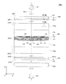
図7は、第2実施形態のプロジェクターに組み込まれるB光用の液晶ライトバルブ25
aの構造を説明する拡大断面図である。この液晶ライトバルブ25aの場合、第1基板7
2の外側には、光透過性の入射側防塵板174aが貼り付けられており、第2基板73の
外側には、光透過性の射出側防塵板174bが貼り付けられている。これらの防塵板17
4a,174bは、ともに平板状であり、偏光フィルター25e等と同様に、入出射面の
法線がシステム光軸SAすなわちZ軸に平行になるように配置されている。ここで、入射
側防塵板174aは、等方性の無機材料、具体的には石英ガラス製の平板であり、射出側
防塵板174bは、正の一軸性の結晶材料、具体的には水晶製の平板である。射出側防塵
板174bは、これを形成する水晶の光学軸がY軸方向に延びるように切り出されたもの
である。つまり、射出側防塵板174bの光学軸は、偏光フィルター25hの吸収軸に対
して垂直な状態になっている。
FIG. 7 shows a liquid crystal
It is an expanded sectional view explaining the structure of a. In the case of this liquid crystal
A light-transmitting incident-
Both 4a and 174b have a flat plate shape, and are arranged so that the normal line of the incident / exit surface is parallel to the system optical axis SA, that is, the Z axis, like the
図8(A)は、本実施形態の液晶ライトバルブ25aのコントラスト比の視野角特性を
説明する図である。なお、この例では、入射側防塵板74aを形成する水晶板の厚みtを
1.1mmとしている。図からも明らかなように、本実施形態の液晶ライトバルブ25a
の場合、比較的広い視野角範囲でコントラスト比が比較的高くなっている。図8(B)は
、比較例の液晶ライトバルブのコントラスト比の視野角特性を説明する図である。比較例
の液晶ライトバルブは、液晶ライトバルブ25a等と基本的に同様の構造を有するが、射
出側防塵板174bの光学軸が、偏光フィルター25hの吸収軸に対して平行に配置され
ている。つまり、比較例の射出側防塵板174bの光学軸はX軸方向に延びている。比較
例の場合、コントラスト比の高い範囲が多少狭くなっている。
FIG. 8A is a diagram illustrating the viewing angle characteristics of the contrast ratio of the liquid crystal
In this case, the contrast ratio is relatively high in a relatively wide viewing angle range. FIG. 8B is a diagram for explaining the viewing angle characteristics of the contrast ratio of the liquid crystal light valve of the comparative example. The liquid crystal light valve of the comparative example has basically the same structure as the liquid crystal
なお、詳細な説明を省略するが、本実施形態におけるR光用の液晶ライトバルブ25c
も、B光用の液晶ライトバルブ25aと同様の構造を有する。つまり、射出側防塵板17
4bが正の一軸性の結晶材料で形成されており、その光学軸が偏光フィルター25jの吸
収軸に対して垂直に配置される。また、本実施形態におけるG光用の液晶ライトバルブ2
5bも、B光用の液晶ライトバルブ25aと同様の構造を有する。つまり、射出側防塵板
174bが正の一軸性の結晶材料で形成されており、その光学軸が偏光フィルター25i
の吸収軸に対して垂直に配置される。ただし、偏光フィルター25iの光射出側には、1
/2波長板25pが追加される。
Although not described in detail, the liquid crystal
Has the same structure as the liquid crystal
4b is made of a positive uniaxial crystal material, and its optical axis is arranged perpendicular to the absorption axis of the
5b also has the same structure as the liquid crystal
Is arranged perpendicular to the absorption axis. However, on the light exit side of the
A / 2
〔第3実施形態〕
以下、本発明に係る第3実施形態の変調光学系を組み込んだプロジェクターについて説
明する。第3実施形態のプロジェクターは、第1実施形態のプロジェクターを変形したも
のであり、特に説明しない部分は、第1実施形態と同様である。
[Third Embodiment]
A projector incorporating the modulation optical system according to the third embodiment of the present invention will be described below. The projector according to the third embodiment is a modification of the projector according to the first embodiment, and portions not specifically described are the same as those in the first embodiment.
図9は、第3実施形態のプロジェクターに組み込まれるB光用の液晶ライトバルブ22
5aの構造を説明する拡大断面図である。この液晶ライトバルブ225aの場合、第1基
板72の外側に貼り付けられた入射側防塵板274aは、負の一軸性の結晶材料であるサ
ファイアで形成され、このサファイアの光学軸がX軸方向に延びるように切り出されたも
のである。つまり、入射側防塵板274aの光学軸は、偏光フィルター25eの吸収軸に
対して垂直な状態になっている。一方、射出側防塵板274bは、等方性の無機材料、具
体的には石英ガラス製の平板である。入射側防塵板274aや射出側防塵板274bは、
入出射面の法線がシステム光軸SAすなわちZ軸に平行になるように配置されている。
FIG. 9 shows a liquid crystal light valve 22 for B light incorporated in the projector of the third embodiment.
It is an expanded sectional view explaining the structure of 5a. In the case of the liquid
The normal line of the incident / exit surface is arranged so as to be parallel to the system optical axis SA, that is, the Z axis.
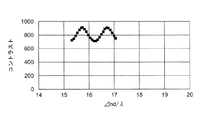
図10は、液晶ライトバルブ225a中において入射側防塵板274aの厚みを変化さ
せた場合のコントラスト比の変化を説明するグラフである。なお、この例では、入射側防
塵板74aを形成する水晶板の厚みtの調整範囲を1040〜1160μmとした。グラ
フからも明らかなように、入射側防塵板274aの厚みを変化させることにより、コント
ラスト比が平均値800を中心として正弦的な変化で増減することがわかる。この場合の
変化の周期は、Δnd/λであり、N〜N−1/2の範囲内にピークが存在し、この範囲
でコントラスト比が相対的に向上することがわかる。つまり、以下の関係式
N≦Δnd/λ≦N−1/2 … (2)
を満たすように、入射側防塵板274aの屈折率差Δnや厚みdを調整することで、入射
側防塵板で生じる位相差が液晶ライトバルブ25aで生じる位相差を打ち消す特性を持た
せることができる。これにより液晶ライトバルブ25aの視野角特性が補償され、コント
ラストが向上する。ここで、入射側防塵板274aの働きについて考察すると、本実施形
態のように、入射側防塵板274aの光学軸が偏光フィルター25eの吸収軸に対して垂
直な状態になっている場合、入射側防塵板274a及び偏光フィルター25eを一組とす
る複合光学素子は、システム光軸SAに平行な方向に光学軸を有する一軸性の素子に似た
作用を及ぼすといえる。特に、Δnd/λが関係式(2)の範囲内にある場合、上記複合
光学素子は見かけ上負の一軸性の作用を及ぼすと考えられる。ここで、垂直配向型の液晶
パネル26aについては、システム光軸SAに平行な方向に光学軸を有する負の一軸性の
光学素子による補償効果があることが確かめられている。よって、関係式(2)の範囲内
となるように入射側防塵板274aの屈折率差Δnや厚みdを調整することで、液晶ライ
トバルブ25aのコントラスト比が若干上昇するものと考えられる。
FIG. 10 is a graph for explaining a change in contrast ratio when the thickness of the incident-
By adjusting the refractive index difference Δn and the thickness d of the incident-
入射側防塵板274aが負の一軸性の結晶材料である場合、図6に示す正の一軸性の結
晶材料からなる入射側防塵板74aと比較して変化が半周期ずれる理由については、明確
でないが、吸収軸方向と入射側防塵板274aの低屈折率方向および高屈折率方向の関係
により、液晶ライトバルブ225aの視野角を補償する特性を有する複屈折特性を持たせ
るために必要な厚みが異なるからであると考えられる。
When the incident-
なお、本実施形態におけるR光用の液晶ライトバルブ225cも、B光用の液晶ライト
バルブ225aと同様の構造を有する。つまり、入射側防塵板274aが負の一軸性の結
晶材料で形成されており、その光学軸が偏光フィルター25gの吸収軸に対して垂直に配
置される(図9参照)。また、本実施形態におけるG光用の液晶ライトバルブ225bも
、B光用の液晶ライトバルブ225aと同様の構造を有する。つまり、入射側防塵板27
4aが負一軸性の結晶材料で形成されており、その光学軸が偏光フィルター25fの吸収
軸に対して垂直に配置される。ただし、偏光フィルター25iの光射出側には、1/2波
長板25pが追加される(図11参照)。
In addition, the liquid crystal
4a is made of a negative uniaxial crystal material, and its optical axis is arranged perpendicular to the absorption axis of the
〔第4実施形態〕
以下、本発明に係る第4実施形態の変調光学系を組み込んだプロジェクターについて説
明する。第4実施形態のプロジェクターは、第3実施形態のプロジェクターを変形したも
のであり、特に説明しない部分は、第3実施形態と同様である。
[Fourth Embodiment]
Hereinafter, a projector incorporating the modulation optical system according to the fourth embodiment of the invention will be described. The projector according to the fourth embodiment is a modification of the projector according to the third embodiment, and parts not specifically described are the same as those of the third embodiment.
図12は、第4実施形態のプロジェクターに組み込まれるB光用の液晶ライトバルブ2
25aの構造を説明する拡大断面図である。この液晶ライトバルブ225aの場合、第1
基板72の外側には、光透過性の入射側防塵板374aが貼り付けられており、第2基板
73の外側には、光透過性の射出側防塵板374bが貼り付けられている。これらの防塵
板374a,374bは、ともに平板状であり、偏光フィルター25e等と同様に、入出
射面の法線がシステム光軸SAすなわちZ軸に平行になるように配置されている。ここで
、入射側防塵板374aは、等方性の無機材料、具体的には石英ガラス製の平板であり、
射出側防塵板374bは、負の一軸性の結晶材料、具体的にはサファイア製の平板である
。射出側防塵板374bは、これを形成するサファイアの光学軸がY軸方向に延びるよう
に切り出されたものである。つまり、射出側防塵板374bの光学軸は、偏光フィルター
25hの吸収軸に対して垂直な状態になっている。
FIG. 12 shows a liquid crystal
It is an expanded sectional view explaining the structure of 25a. In the case of this liquid
A light transmissive incident side
The emission-
なお、詳細な説明を省略するが、本実施形態におけるR光用の液晶ライトバルブ225
cも、B光用の液晶ライトバルブ225aと同様の構造を有する。つまり、射出側防塵板
374bが負の一軸性の結晶材料で形成されており、その光学軸が偏光フィルター25j
の吸収軸に対して垂直に配置される。また、本実施形態におけるG光用の液晶ライトバル
ブ225bも、B光用の液晶ライトバルブ225aと同様の構造を有する。つまり、射出
側防塵板374bが負の一軸性の結晶材料で形成されており、その光学軸が偏光フィルタ
ー25iの吸収軸に対して垂直に配置される。ただし、偏光フィルター25iの光射出側
には、1/2波長板25pが追加される。
Although not described in detail, the liquid crystal light valve 225 for R light in this embodiment is used.
c also has the same structure as the liquid
Is arranged perpendicular to the absorption axis. The liquid crystal
〔第5実施形態〕
以下、第5実施形態の変調光学系を組み込んだプロジェクターについて説明する。第5
実施形態のプロジェクターは、第1〜第4実施形態のプロジェクターを変形したものであ
り、特に説明しない部分は、第1実施形態等と同様である。
[Fifth Embodiment]
Hereinafter, a projector incorporating the modulation optical system according to the fifth embodiment will be described. 5th
The projector according to the embodiment is a modification of the projector according to the first to fourth embodiments, and parts not specifically described are the same as those of the first embodiment.
第5実施形態のプロジェクターに組み込まれる液晶ライトバルブ25a,25b,25
c,225a,225b,225cは、ツイストネマティックモードで動作する液晶(す
なわちツイストネマティック型の液晶)で構成される液晶層71を備える。この場合、液
晶層71中の液晶性化合物の光学軸は、第1基板72から第2基板73にかけて徐々にね
じれるように配置される。つまり、第1及び第2基板72,73の内側すなわち配向膜7
6,78に隣接して液晶層71の両端側に配置される一組の液晶性化合物の光学軸は、X
Y平面上に投影した場合、互いに例えば90°のツイスト角をなす。これにより、一対の
偏光フィルムPF1,PF2の間に挟まれた液晶層71をノーマリホワイトモードで動作
させることになり、電圧非印加のオフ状態で最大透過状態(光オン状態)を確保すること
ができる。つまり、液晶パネル26aは、光オン状態の白表示時に、S偏光をP偏光に切
替えて通過させるとともに、光オフ状態の黒表示時に、P偏光をそのまま変化させないで
通過させる。
Liquid
c, 225a, 225b, and 225c each include a
The optical axes of a pair of liquid crystal compounds disposed on both end sides of the
When projected onto the Y plane, they form a twist angle of 90 °, for example. As a result, the
なお、例えば第1実施形態のプロジェクター10を変更したものでは、偏光フィルター
25e,25f,25gの吸収軸の方向と、正の一軸性の結晶材料である入射側防塵板7
4aの光学軸の方向とが直交する点に変更はない。また、第2実施形態のプロジェクター
10を変更したものでは、偏光フィルター25h,25i,25jの吸収軸の方向と、正
の一軸性の結晶である射出側防塵板174bの光学軸の方向とが直交する点に変更はない
。同様に、第3実施形態のプロジェクター10を変更したものでは、偏光フィルター25
e,25f,25gの吸収軸の方向と、負の一軸性の結晶材料である入射側防塵板274
aの光学軸の方向とが直交する点に変更はない。また、第4実施形態のプロジェクター1
0を変更したものでは、偏光フィルター25h,25i,25jの吸収軸の方向と、負の
一軸性の結晶である射出側防塵板374bの光学軸の方向とが直交する点に変更はない。
For example, when the
There is no change in the point where the direction of the optical axis 4a is orthogonal. Moreover, in the
e, 25f, 25g absorption axis direction and incident-side dustproof plate 274 which is a negative uniaxial crystal material
There is no change in the point where the direction of the optical axis a is orthogonal. Further, the
In the case where 0 is changed, there is no change in that the direction of the absorption axis of the
図13は、第1実施形態をツイストネマティック型に変更した液晶ライトバルブ25a
中において入射側防塵板74aの厚みを変化させた場合のコントラスト比の変化を説明す
るグラフである。ここで、曲線aは、偏光フィルター25eの吸収軸の方向と、入射側防
塵板74aの光学軸の方向とが直交する場合のコントラスト比の変化を示す。一方、曲線
bは、偏光フィルター25eの吸収軸の方向と、入射側防塵板74aの光学軸の方向とが
平行な場合のコントラスト比の変化を示す。
FIG. 13 shows a liquid crystal
It is a graph explaining the change of contrast ratio at the time of changing the thickness of the incident side dust-
グラフからも明らかなように、入射側防塵板74aの厚みを変化させることにより、コ
ントラスト比が正弦的な変化で増減することがわかる。この場合の変化の周期は、Δnd
であり、N〜N+1/2の範囲内にピークが存在しこの範囲でコントラスト比が相対的に
向上することがわかる。つまり、ツイストネマティック型の液晶層71を備える液晶パネ
ル26aであっても、以下の関係式
N≦Δnd/λ≦N+1/2 … (1)
を満たすように、入射側防塵板74aの屈折率差Δnや厚みdを調整することで、入射側
防塵板で生じる位相差が液晶ライトバルブ25a,225aで生じる位相差を打ち消す特
性を持たせることができる。これにより液晶ライトバルブ25a,225aの視野角特性
が補償され、コントラストが向上する。ここで、入射側防塵板74a,274aの働きに
ついて考察すると、本実施形態のように、入射側防塵板74a,274aの光学軸が偏光
フィルター25eの吸収軸に対して垂直な状態になっている場合、入射側防塵板74a,
274a及び偏光フィルター25eを一組とする複合光学素子は、システム光軸SAに平
行な方向に光学軸を有する一軸性の素子に似た作用を及ぼすといえる。特に、Δnd/λ
が関係式(1)の範囲内にある場合、上記複合光学素子は、見かけ上負の一軸性の作用を
及ぼすと考えられる。前述したように、ツイストネマティック型の液晶パネル26aにつ
いては、システム光軸SAに平行な方向に光学軸を有する負の一軸性の光学素子による補
償効果があることが確かめられている。よって、関係式(1)の範囲内となるように入射
側防塵板74aの屈折率差Δnや厚みdを調整することで、液晶ライトバルブ25a,2
25aのコントラスト比が若干上昇するものと考えられる。
As is apparent from the graph, it is understood that the contrast ratio increases or decreases with a sine change by changing the thickness of the incident-
It can be seen that there is a peak in the range of N to N + 1/2, and the contrast ratio is relatively improved in this range. That is, even in the
By adjusting the refractive index difference Δn and the thickness d of the incident-
It can be said that the composite optical element including the pair of 274a and the
Is in the range of the relational expression (1), it is considered that the composite optical element has an apparently negative uniaxial effect. As described above, it has been confirmed that the twisted nematic
It is considered that the contrast ratio of 25a is slightly increased.
以上実施形態に即して本発明を説明したが、本発明は、上記の実施形態に限られるもの
ではなく、その要旨を逸脱しない範囲において種々の態様において実施することが可能で
あり、例えば次のような変形も可能である。
Although the present invention has been described based on the above embodiments, the present invention is not limited to the above embodiments, and can be implemented in various modes without departing from the gist thereof. Such modifications are also possible.
すなわち、上記第1及び第3実施形態では、入射側防塵板74aを正又は負の一軸性結
晶とし、上記第2及び第4実施形態では、射出側防塵板74bを正又は負の一軸性結晶と
したが、入射側防塵板及び射出側防塵板の双方を正又は負の一軸性結晶とすることができ
る。
That is, in the first and third embodiments, the incident-
また、上記第1〜第5実施形態では、光学補償板を組み込んでいないが、液晶ライトバ
ルブ25a,25b,25cにおいて、例えば偏光フィルター25e,25f,25gと
、液晶パネル26a,26b,26cとの間に結晶材料からなり位相差を付与することが
できる光学補償板を挿入することができる。
In the first to fifth embodiments, an optical compensator is not incorporated. However, in the liquid
また、上記実施形態のプロジェクター10では、光源装置21を、光源ランプ21a、
一対のレンズアレイ21d,21e、偏光変換部材21g、及び重畳レンズ21iで構成
したが、レンズアレイ21d,21e等については省略することができ、光源ランプ21
aも、LED等の別光源に置き換えることができる。
In the
Although the pair of
a can also be replaced with another light source such as an LED.
上記実施形態では、3つの液晶ライトバルブ25a〜25cを用いたプロジェクター1
0の例のみを挙げたが、本発明は、2つの液晶ライトバルブを用いたプロジェクター、或
いは、4つ以上の液晶ライトバルブを用いたプロジェクターにも適用可能である。
In the above embodiment, the
Although only an example of 0 is given, the present invention is also applicable to a projector using two liquid crystal light valves or a projector using four or more liquid crystal light valves.
上記実施形態では、スクリーンを観察する方向から投射を行なうフロントタイプのプロ
ジェクターの例のみを挙げたが、本発明は、スクリーンを観察する方向とは反対側から投
射を行なうリアタイプのプロジェクターにも適用可能である。
In the above embodiment, only an example of a front type projector that projects from the direction of observing the screen is given, but the present invention is also applicable to a rear type projector that projects from the side opposite to the direction of observing the screen. Is possible.
LI…入射光、 LO…射出光、 OA…光学軸、 OP1,OP2,OP3…光路、
PF1,PF2…偏光フィルム、 S1…基板、 S2…基板、 SA…システム光軸、
10…プロジェクター、 21…光源装置、 21g…偏光変換部材、 21i…重畳
レンズ、 23…色分離光学系、 23a,23b…ダイクロイックミラー、 25…光
変調部、 25a,25b,25c,225a,225b,225c…液晶ライトバルブ
、 25e,25f,25g…偏光フィルター、 25h,25i,25j…偏光フィル
ター、 25p…波長板、 26a,26b,26c…液晶パネル、 27…クロスダイ
クロイックプリズム、 27a,27b…ダイクロミラー、 29…投射レンズ、 71
…液晶層、 72,73…基板、 74a,174a,274a,374a…入射側防塵
板、 74b,174b,274b,374b…射出側防塵板、 75,77…電極、
76,78…配向膜、 77…透明画素電極、 80…液晶デバイス
74a,74b 防塵板
LI ... incident light, LO ... emitted light, OA ... optical axis, OP1, OP2, OP3 ... optical path,
PF1, PF2 ... polarizing film, S1 ... substrate, S2 ... substrate, SA ... system optical axis,
DESCRIPTION OF
Liquid crystal layer, 72, 73 ... Substrate, 74a, 174a, 274a, 374a ... Incident side dustproof plate, 74b, 174b, 274b, 374b ... Ejection side dustproof plate, 75, 77 ... Electrode,
76, 78 ... Alignment film, 77 ... Transparent pixel electrode, 80 ...
Claims (8)
れる防塵板を有する液晶パネルと、
前記防塵板を挟んで前記液晶パネルに対向して配置される偏光フィルターと、を備える
液晶表示装置であって、
前記偏光フィルターの吸収軸の方向と前記防塵板の光学軸の方向とは直交し、
前記防塵板は、正の一軸性の結晶材料で形成され、システム光軸に垂直な2方向に関す
る屈折率差をΔnとし、システム光軸方向の厚みをdとし、使用する波長をλとしたとき
に、整数Nを用いて、以下の関係式
N≦Δnd/λ≦N+1/2
を満たす液晶表示装置。 A liquid crystal device, and a liquid crystal panel having a dustproof plate disposed on at least one of a light incident side and a light emission side of the liquid crystal device;
A polarizing filter disposed opposite to the liquid crystal panel with the dustproof plate in between, and a liquid crystal display device comprising:
The direction of the absorption axis of the polarizing filter and the direction of the optical axis of the dustproof plate are orthogonal,
The dust-proof plate is made of a positive uniaxial crystal material, and when the refractive index difference in two directions perpendicular to the system optical axis is Δn, the thickness in the system optical axis direction is d, and the wavelength to be used is λ And using the integer N, the following relational expression N ≦ Δnd / λ ≦ N + 1/2
A liquid crystal display device that satisfies the requirements.
れる防塵板を有する液晶パネルと、
前記防塵板を挟んで前記液晶パネルに対向して配置される偏光フィルターと、を備える
液晶表示装置であって、
前記偏光フィルターの吸収軸の方向と前記防塵板の光学軸の方向とは直交し、
前記防塵板は、負の一軸性の結晶材料で形成され、システム光軸に垂直な2方向に関す
る屈折率差をΔnとし、システム光軸方向の厚みをdとし、使用する波長をλとしたとき
に、整数Nを用いて、以下の関係式
N≦Δnd/λ≦N−1/2
を満たす液晶表示装置。 A liquid crystal device, and a liquid crystal panel having a dustproof plate disposed on at least one of a light incident side and a light emission side of the liquid crystal device;
A polarizing filter disposed opposite to the liquid crystal panel with the dustproof plate in between, and a liquid crystal display device comprising:
The direction of the absorption axis of the polarizing filter and the direction of the optical axis of the dustproof plate are orthogonal,
The dust-proof plate is made of a negative uniaxial crystal material, and when the refractive index difference in two directions perpendicular to the system optical axis is Δn, the thickness in the system optical axis direction is d, and the wavelength to be used is λ And using the integer N, the following relational expression N ≦ Δnd / λ ≦ N−1 / 2
A liquid crystal display device that satisfies the requirements.
板上に形成される表示用電極とを有する、請求項1から請求項4までのいずれか一項に記
載の液晶表示装置。 5. The liquid crystal device according to claim 1, wherein the liquid crystal device includes a pair of substrates sandwiching a liquid crystal layer, and a display electrode formed on one of the pair of substrates. The liquid crystal display device described.
らに備える、請求項1から請求項5までのいずれか一項に記載の液晶表示装置。 The liquid crystal display device according to any one of claims 1 to 5, further comprising a polarizing filter disposed on the opposite side of the polarizing filter with the liquid crystal panel interposed therebetween.
前記照明装置から射出された光束から複数の色光を分離して、前記複数の色光を各色の
光路にそれぞれ導く色分離光学系と、
前記各色の光路上に配置される請求項1から請求項6までのいずれか一項に記載の液晶
表示装置を有し、前記複数の色光を画像情報に応じて変調する光変調部と、
前記各色の光路上に配置される各色の液晶表示装置からの各色の変調光を合成して射出
する光合成光学系と、
前記光合成光学系を経て合成された変調光を投射する投射光学系と、
を備えるプロジェクター。 An illumination device that emits a luminous flux;
A color separation optical system that separates a plurality of color lights from a light beam emitted from the illumination device and guides the plurality of color lights to an optical path of each color;
An optical modulation unit comprising the liquid crystal display device according to any one of claims 1 to 6 disposed on the optical path of each color, and modulating the plurality of color lights according to image information;
A light combining optical system that combines and emits the modulated light of each color from the liquid crystal display device of each color arranged on the optical path of each color;
A projection optical system for projecting the modulated light synthesized through the light synthesis optical system;
A projector comprising:
前記各色の液晶表示装置は、偏光方向が共通の色光を変調し、
前記光合成光学系は、システム光軸を通ってシステム光軸に垂直な軸のまわりに傾斜し
た少なくとも1つのダイクロイックミラーを有し、各色の像光を前記少なくとも1つのダ
イクロイックミラーの波長特性を利用して合成し、
前記光変調部は、前記各色の液晶表示装置として、前記少なくとも1つのダイクロイッ
クミラーで反射される変調光を射出する第1タイプの液晶表示装置と、前記少なくとも1
つのダイクロイックミラーを透過させる変調光を射出する第2タイプの液晶表示装置とを
有し、前記第1タイプの液晶表示装置と前記第2タイプの液晶表示装置とのいずれか一方
と、前記光合成光学系との間に、偏光方向を90°切り換える波長板を有する、請求項7
に記載のプロジェクター。 The illumination device emits illumination light whose polarization direction is aligned in a predetermined direction,
Each color liquid crystal display device modulates color light having a common polarization direction,
The light combining optical system has at least one dichroic mirror inclined through an optical axis through the system optical axis and about an axis perpendicular to the system optical axis, and uses the wavelength characteristics of the at least one dichroic mirror for image light of each color. Synthesize
The light modulation unit includes a first type liquid crystal display device that emits modulated light reflected by the at least one dichroic mirror, and the at least one liquid crystal display device for each color.
A second type liquid crystal display device that emits modulated light that is transmitted through two dichroic mirrors, one of the first type liquid crystal display device and the second type liquid crystal display device, and the light combining optics A wave plate for switching the polarization direction by 90 ° is provided between the system and the system.
Projector.
Priority Applications (4)
| Application Number | Priority Date | Filing Date | Title |
|---|---|---|---|
| JP2008332977A JP2010152268A (en) | 2008-12-26 | 2008-12-26 | Liquid crystal display device and projector |
| US12/644,986 US20100165220A1 (en) | 2008-12-26 | 2009-12-22 | Liquid crystal display device and projector |
| CN2009102588498A CN101770110B (en) | 2008-12-26 | 2009-12-25 | Liquid crystal display and projector |
| US13/596,746 US20120320289A1 (en) | 2008-12-26 | 2012-08-28 | Liquid Crystal Display Device and Projector |
Applications Claiming Priority (1)
| Application Number | Priority Date | Filing Date | Title |
|---|---|---|---|
| JP2008332977A JP2010152268A (en) | 2008-12-26 | 2008-12-26 | Liquid crystal display device and projector |
Publications (2)
| Publication Number | Publication Date |
|---|---|
| JP2010152268A true JP2010152268A (en) | 2010-07-08 |
| JP2010152268A5 JP2010152268A5 (en) | 2012-01-19 |
Family
ID=42284502
Family Applications (1)
| Application Number | Title | Priority Date | Filing Date |
|---|---|---|---|
| JP2008332977A Withdrawn JP2010152268A (en) | 2008-12-26 | 2008-12-26 | Liquid crystal display device and projector |
Country Status (3)
| Country | Link |
|---|---|
| US (2) | US20100165220A1 (en) |
| JP (1) | JP2010152268A (en) |
| CN (1) | CN101770110B (en) |
Families Citing this family (6)
| Publication number | Priority date | Publication date | Assignee | Title |
|---|---|---|---|---|
| US8368824B2 (en) * | 2009-01-22 | 2013-02-05 | Seiko Epson Corporation | Liquid crystal display apparatus and projector |
| TW201504087A (en) * | 2013-07-23 | 2015-02-01 | Hon Hai Prec Ind Co Ltd | Vehicle headlamp module |
| US20180088378A1 (en) * | 2016-09-28 | 2018-03-29 | Electronics And Telecommunications Research Institute | Polarimetric-analysis-type dual liquid crystal wavelength filter module |
| CN109981934A (en) * | 2017-12-28 | 2019-07-05 | 重庆国太科技有限公司 | A kind of automatic dust removing photographic device |
| JP7266031B2 (en) * | 2018-06-05 | 2023-04-27 | ソニーセミコンダクタソリューションズ株式会社 | Liquid crystal display device and projection display device |
| JP2021033032A (en) * | 2019-08-23 | 2021-03-01 | セイコーエプソン株式会社 | projector |
Citations (5)
| Publication number | Priority date | Publication date | Assignee | Title |
|---|---|---|---|---|
| JPH10186548A (en) * | 1996-10-30 | 1998-07-14 | Seiko Epson Corp | Projection type display device |
| JPH11337919A (en) * | 1998-03-27 | 1999-12-10 | Kyocera Corp | Liquid crystal projector |
| JP2003195252A (en) * | 2001-12-26 | 2003-07-09 | Kinseki Ltd | Liquid crystal projector |
| JP2003322848A (en) * | 2002-04-30 | 2003-11-14 | Toyo Commun Equip Co Ltd | Polarizing plate, liquid crystal unit and liquid crystal projector |
| JP2004245914A (en) * | 2003-02-12 | 2004-09-02 | Kyocera Corp | Liquid crystal projector device and transparent plate used for same, and liquid crystal display panel |
Family Cites Families (12)
| Publication number | Priority date | Publication date | Assignee | Title |
|---|---|---|---|---|
| CA2005096C (en) * | 1988-12-13 | 1999-03-23 | Tokinori Agou | High light-transmissive dust-proof body and method of preparing same |
| JP2002072162A (en) * | 2000-09-01 | 2002-03-12 | Seiko Epson Corp | Liquid crystal light valve and projection type display device equipped with the same |
| JP3867597B2 (en) * | 2002-03-19 | 2007-01-10 | セイコーエプソン株式会社 | Electro-optical device, electronic apparatus, and projection display device |
| US6819464B2 (en) * | 2002-06-19 | 2004-11-16 | Seiko Epson Corporation | Optical modulator, optical device and projector |
| JP3864929B2 (en) * | 2003-04-15 | 2007-01-10 | ソニー株式会社 | Liquid crystal display device, image display device |
| JP2005037503A (en) * | 2003-07-16 | 2005-02-10 | Seiko Epson Corp | Spatial light modulation system and projector |
| JP4511275B2 (en) * | 2004-01-30 | 2010-07-28 | 三洋電機株式会社 | Projection display device |
| JP4055762B2 (en) * | 2004-05-25 | 2008-03-05 | セイコーエプソン株式会社 | Manufacturing method of electro-optical device |
| JP2006350291A (en) * | 2005-05-17 | 2006-12-28 | Seiko Epson Corp | Liquid crystal projector |
| JP4572165B2 (en) * | 2005-12-08 | 2010-10-27 | Necディスプレイソリューションズ株式会社 | Projection display |
| US8089498B2 (en) * | 2006-04-28 | 2012-01-03 | Ricoh Company, Ltd. | Surface-emission laser array, optical scanning apparatus apparatus and image forming apparatus |
| JP2008250234A (en) * | 2007-03-30 | 2008-10-16 | Fujifilm Corp | Liquid crystal display |
-
2008
- 2008-12-26 JP JP2008332977A patent/JP2010152268A/en not_active Withdrawn
-
2009
- 2009-12-22 US US12/644,986 patent/US20100165220A1/en not_active Abandoned
- 2009-12-25 CN CN2009102588498A patent/CN101770110B/en active Active
-
2012
- 2012-08-28 US US13/596,746 patent/US20120320289A1/en not_active Abandoned
Patent Citations (5)
| Publication number | Priority date | Publication date | Assignee | Title |
|---|---|---|---|---|
| JPH10186548A (en) * | 1996-10-30 | 1998-07-14 | Seiko Epson Corp | Projection type display device |
| JPH11337919A (en) * | 1998-03-27 | 1999-12-10 | Kyocera Corp | Liquid crystal projector |
| JP2003195252A (en) * | 2001-12-26 | 2003-07-09 | Kinseki Ltd | Liquid crystal projector |
| JP2003322848A (en) * | 2002-04-30 | 2003-11-14 | Toyo Commun Equip Co Ltd | Polarizing plate, liquid crystal unit and liquid crystal projector |
| JP2004245914A (en) * | 2003-02-12 | 2004-09-02 | Kyocera Corp | Liquid crystal projector device and transparent plate used for same, and liquid crystal display panel |
Also Published As
| Publication number | Publication date |
|---|---|
| US20120320289A1 (en) | 2012-12-20 |
| CN101770110A (en) | 2010-07-07 |
| CN101770110B (en) | 2011-12-14 |
| US20100165220A1 (en) | 2010-07-01 |
Similar Documents
| Publication | Publication Date | Title |
|---|---|---|
| JP4301327B2 (en) | Projector with optical device | |
| TWI432874B (en) | Projection type liquid crystal display and compensation plate | |
| JP5446591B2 (en) | projector | |
| US20060262233A1 (en) | Liquid crystal projector | |
| JPWO2007105371A1 (en) | Liquid crystal device and projector provided with the same | |
| US20120320289A1 (en) | Liquid Crystal Display Device and Projector | |
| JP2009217218A (en) | Projector | |
| JP2003270636A (en) | Liquid crystal panel, liquid crystal device, and projector using liquid crystal device | |
| US8368824B2 (en) | Liquid crystal display apparatus and projector | |
| US11256140B2 (en) | Liquid crystal display apparatus and display method | |
| JP2007304229A (en) | Optical element and projection apparatus | |
| JP2010217360A (en) | Projector | |
| JP2010169852A (en) | Liquid crystal display and projector | |
| JP2008176168A (en) | Liquid crystal device and projector provided with the same | |
| JP2010152269A (en) | Liquid crystal display device and projector | |
| JP4479846B2 (en) | Liquid crystal display device and projector | |
| JP5402261B2 (en) | Electro-optical display device and projector | |
| JP5459056B2 (en) | projector | |
| WO2021015101A1 (en) | Display device | |
| JP2008026538A (en) | Optical device and projector equipped with the same | |
| JP2008015300A (en) | Optical apparatus and projector equipped therewith | |
| JP2007264245A (en) | Image projector | |
| US8023050B2 (en) | Optical device and projector | |
| JP2010169851A (en) | Liquid crystal display and projector | |
| JP5541204B2 (en) | projector |
Legal Events
| Date | Code | Title | Description |
|---|---|---|---|
| A521 | Written amendment |
Free format text: JAPANESE INTERMEDIATE CODE: A523 Effective date: 20111125 |
|
| A621 | Written request for application examination |
Free format text: JAPANESE INTERMEDIATE CODE: A621 Effective date: 20111125 |
|
| A977 | Report on retrieval |
Free format text: JAPANESE INTERMEDIATE CODE: A971007 Effective date: 20121107 |
|
| A131 | Notification of reasons for refusal |
Free format text: JAPANESE INTERMEDIATE CODE: A131 Effective date: 20121113 |
|
| A761 | Written withdrawal of application |
Free format text: JAPANESE INTERMEDIATE CODE: A761 Effective date: 20130109 |