JP2010149733A - Head-up display - Google Patents
Head-up display Download PDFInfo
- Publication number
- JP2010149733A JP2010149733A JP2008330775A JP2008330775A JP2010149733A JP 2010149733 A JP2010149733 A JP 2010149733A JP 2008330775 A JP2008330775 A JP 2008330775A JP 2008330775 A JP2008330775 A JP 2008330775A JP 2010149733 A JP2010149733 A JP 2010149733A
- Authority
- JP
- Japan
- Prior art keywords
- width direction
- display
- vehicle width
- vehicle
- virtual image
- Prior art date
- Legal status (The legal status is an assumption and is not a legal conclusion. Google has not performed a legal analysis and makes no representation as to the accuracy of the status listed.)
- Granted
Links
- 230000008859 change Effects 0.000 abstract description 10
- 230000006866 deterioration Effects 0.000 abstract 1
- 238000000034 method Methods 0.000 description 10
- 230000008569 process Effects 0.000 description 10
- 230000005540 biological transmission Effects 0.000 description 7
- 230000006872 improvement Effects 0.000 description 7
- 238000001514 detection method Methods 0.000 description 6
- 230000004044 response Effects 0.000 description 5
- 238000010586 diagram Methods 0.000 description 4
- 230000009471 action Effects 0.000 description 3
- 230000000694 effects Effects 0.000 description 3
- 230000004308 accommodation Effects 0.000 description 2
- 230000006870 function Effects 0.000 description 2
- 230000007246 mechanism Effects 0.000 description 2
- 230000003287 optical effect Effects 0.000 description 2
- 238000005401 electroluminescence Methods 0.000 description 1
- 239000011521 glass Substances 0.000 description 1
- 210000003128 head Anatomy 0.000 description 1
- 239000004973 liquid crystal related substance Substances 0.000 description 1
- 239000002184 metal Substances 0.000 description 1
- 230000004048 modification Effects 0.000 description 1
- 238000012986 modification Methods 0.000 description 1
- 230000009467 reduction Effects 0.000 description 1
- 230000003014 reinforcing effect Effects 0.000 description 1
- 229920003002 synthetic resin Polymers 0.000 description 1
- 239000000057 synthetic resin Substances 0.000 description 1
Images


Landscapes
- Fittings On The Vehicle Exterior For Carrying Loads, And Devices For Holding Or Mounting Articles (AREA)
- Instrument Panels (AREA)
Abstract
Description
本発明は、表示源を有し、前記表示源に表示された表示情報の表示光を車両のウインドシールド側投射エリアに投射させ、前記車両のアイポイントから前記ウインドシールドを透して視認される前記車両の前景と、前記投射エリアに投射される表示情報の虚像と、を重畳視認させるヘッドアップディスプレイ装置に関するものである。 The present invention has a display source, projects display light of display information displayed on the display source onto a windshield side projection area of the vehicle, and is visually recognized through the windshield from the eyepoint of the vehicle. The present invention relates to a head-up display device that superimposes and visually recognizes a foreground of the vehicle and a virtual image of display information projected on the projection area.
近年、運転者が運転に際して求める情報の増加や多角化に伴って、情報内容(情報量は少ないが緊急度の高い情報)によっては情報を車両のウインドシールド上に虚像表示させ、それを透して視認させる車両の前景と重畳視認させる、ヘッドアップディスプレイ(HUD)装置が自動車、列車等の車両の運転席に採用されている。 In recent years, along with the increase and diversification of information required by the driver during driving, depending on the information content (information with a small amount of information but high urgency), the information is displayed as a virtual image on the windshield of the vehicle. 2. Description of the Related Art A head-up display (HUD) device that superimposes and visually recognizes a vehicle foreground is used in a driver seat of a vehicle such as an automobile or a train.
このようなHUD装置は、車両のインストルメントパネル(インパネ)内部に表示源を配置し、この表示源の画像を示す表示光を、拡大系ミラー等の反射部材によりウインドシールド、コンバイナ等の投射エリアに向けて反射させ、この表示エリア上に虚像を投射させ、それを透して視認させる車両の前景と重畳視認させる。 In such a HUD device, a display source is arranged inside an instrument panel (instrument panel) of a vehicle, and display light indicating an image of the display source is projected onto a projection area such as a windshield or a combiner by a reflecting member such as an magnifying mirror. The virtual image is projected toward the display area, a virtual image is projected on the display area, and is superimposed and visually recognized with the foreground of the vehicle to be seen through.
ところで、運転者は座高等の個人差により目の高さが異なるため、虚像を視認できる目の位置が狭い範囲に限定されるHUD装置では、前記表示光の投射方向が運転者の目に向かわないと、運転者は重畳表示された表示内容を十分に視認できない。そのため、反射部材の姿勢を調節する調節部材を設け、その調節に応じて前記表示光の投射方向を運転者の目に向かわせるように運転者自身に調節させるHUD装置が開示されている(特許文献1)。
上述したHUD装置では表示位置を運転者に合わせて上下方向に調整可能としてきたが、同一の運転者であっても、渋滞時等における運転者の姿勢の変化、ウインドシールドを透して視認する前景(虚像の背景等)の変化等によっては、従来のように車両の上下方向に調整した虚像でも視認しづらい場合が生じることが分かった。そして、運転中の運転者に対するサービス及び視認性の向上を考慮すると、そのような問題は解消したいとの要望があった。 In the HUD device described above, the display position can be adjusted in the vertical direction according to the driver, but even the same driver can visually recognize changes in the driver's posture during traffic jams, through the windshield, etc. It has been found that depending on the change in the foreground (such as the background of the virtual image), it may be difficult to visually recognize the virtual image adjusted in the vertical direction of the vehicle as in the past. And considering the improvement of service and visibility for the driver while driving, there has been a desire to solve such a problem.
よって本発明は、上述した問題点に鑑み、運転中の運転者の姿勢の変化による虚像の視認性低下を防止するヘッドアップディスプレイ装置を提供することを課題としている。 Therefore, in view of the problems described above, an object of the present invention is to provide a head-up display device that prevents a reduction in the visibility of a virtual image due to a change in the posture of a driver during driving.
上記課題を解決するため本発明によりなされた請求項1記載のヘッドアップディスプレイ装置は、表示源を有し、前記表示源に表示された表示情報の表示光を車両のウインドシールド側投射エリアに投射させ、前記車両のアイポイントから前記ウインドシールドを透して視認される前記車両の前景と、前記投射エリアに投射される表示情報の虚像と、を重畳視認させるヘッドアップディスプレイ装置において、前記投射エリア上における前記表示光の投射位置を前記車両の車幅方向に移動させる車幅方向移動手段と、前記車幅方向における前記虚像を投射すべき選択位置を検出し、その選択位置に前記虚像が移動するように前記車幅方向移動手段の移動を制御する移動制御手段と、を有することを特徴とする。 The head-up display device according to claim 1, which has been made according to the present invention to solve the above-described problem, has a display source, and projects display light of display information displayed on the display source onto a windshield side projection area of the vehicle. In the head-up display device, in which the foreground of the vehicle visually recognized through the windshield from the eye point of the vehicle and the virtual image of the display information projected on the projection area are superimposed and visually recognized, the projection area A vehicle width direction moving means for moving the projection position of the display light in the vehicle width direction of the vehicle and a selection position to project the virtual image in the vehicle width direction are detected, and the virtual image is moved to the selection position. And a movement control means for controlling the movement of the vehicle width direction moving means.
上記請求項1に記載した本発明のヘッドアップディスプレイ装置によれば、渋滞時等における運転者の姿勢の変化、ウインドシールドを透して視認する前景(虚像の背景等)によっては、車両の上下方向に調整した虚像でも、視認しづらい場合が生じた場合等に、車幅方向移動手段によって投射エリアEの車幅方向における虚像を投射すべき選択位置が検出されると、その選択位置に応じて車幅方向移動手段が移動させられることで、投射エリアの車幅方向に表示光の投射位置が選択位置に移動するため、その虚像を車幅方向に移動させることができる。 According to the head-up display device of the present invention described in claim 1 above, depending on a change in the posture of the driver during a traffic jam and the foreground (background of a virtual image) viewed through the windshield, Even when a virtual image adjusted in the direction is difficult to visually recognize, when a selection position where a virtual image in the vehicle width direction of the projection area E is to be projected is detected by the vehicle width direction moving means, the selected position depends on the selection position. By moving the vehicle width direction moving means, the projection position of the display light moves to the selected position in the vehicle width direction of the projection area, so that the virtual image can be moved in the vehicle width direction.
請求項2記載の発明は、請求項1に記載のヘッドアップディスプレイ装置において、前記表示源を収容する収容ケースを有し、前記車幅方向移動手段が、前記虚像を前記車幅方向に移動させるために、前記収容ケースを前記車幅方向に移動させる手段であることを特徴とする。 According to a second aspect of the present invention, in the head-up display device according to the first aspect, the head-up display device includes a housing case that houses the display source, and the vehicle width direction moving unit moves the virtual image in the vehicle width direction. Therefore, it is a means for moving the housing case in the vehicle width direction.
上記請求項2に記載した本発明のヘッドアップディスプレイ装置によれば、表示源を収容した収容ケースを車幅方向移動手段によって車幅方向に移動させることで、虚像を車幅方向に移動させることができる。
According to the head-up display device of the present invention described in
請求項3記載の発明は、請求項2に記載のヘッドアップディスプレイ装置において、前記表示源が、前記ウインドシールドに対向する対向部材に形成された前記車幅方向に延びるスリット状の開口部から、前記表示光を前記投射エリアに向けて出射するように前記対向部材内に設けられた表示源であり、前記対向部材の開口部から前記収容ケースの開口のみが露出するように前記開口部を遮蔽する遮蔽部材を有することを特徴とする。 According to a third aspect of the present invention, in the head-up display device according to the second aspect, the display source is formed from a slit-like opening extending in the vehicle width direction, which is formed in a facing member facing the windshield. A display source provided in the facing member so as to emit the display light toward the projection area, and the opening is shielded so that only the opening of the housing case is exposed from the opening of the facing member. It has the shielding member to do.
上記請求項3に記載した本発明のヘッドアップディスプレイ装置によれば、インストルメントパネル等の対向部材に車幅スリット状の開口部を形成しても、その開口部からは収容ケースの開口のみが露出するように遮蔽部材で隠した状態で、虚像を車幅方向に移動させることができる。 According to the head-up display device of the present invention described in the third aspect, even if the opening portion in the vehicle width slit shape is formed in the facing member such as the instrument panel, only the opening of the housing case is formed from the opening portion. The virtual image can be moved in the vehicle width direction while being hidden by the shielding member so as to be exposed.
請求項4記載の発明は、請求項1に記載のヘッドアップディスプレイ装置において、前記表示源との対向距離が変化するように前記車両の前後方向に移動される第1反射部材と、前記第1反射部材で反射した前記表示光を前記投射エリアに反射し、且つ、前記第1反射部材の前記前後方向への移動量に応じて、前記表示光が前記投射エリアの車幅方向にずれるように設けられた第2反射部材と、を有し、前記車幅方向移動手段が、前記虚像を前記車幅方向に移動させるために、前記第1反射部材を前記車両の前後方向に移動させる手段であることを特徴とする。 According to a fourth aspect of the present invention, in the head-up display device according to the first aspect, the first reflecting member that is moved in the front-rear direction of the vehicle so that the facing distance to the display source changes, and the first The display light reflected by the reflecting member is reflected to the projection area, and the display light is shifted in the vehicle width direction of the projection area according to the amount of movement of the first reflecting member in the front-rear direction. A means for moving the first reflecting member in the longitudinal direction of the vehicle in order to move the virtual image in the vehicle width direction. It is characterized by being.
上記請求項4に記載した本発明のヘッドアップディスプレイ装置によれば、第1反射部材で反射した表示光は第2反射部材で投射エリアに向けて反射する。そして、第1反射部材が車幅方向移動手段によって前後方向に移動されると、その移動量に応じて第2反射部材は表示光を投射エリアの車幅方向にずらした投射位置に向けて反射する。 According to the head-up display device of the present invention, the display light reflected by the first reflecting member is reflected by the second reflecting member toward the projection area. Then, when the first reflecting member is moved in the front-rear direction by the vehicle width direction moving means, the second reflecting member reflects the display light toward the projection position shifted in the vehicle width direction of the projection area according to the movement amount. To do.
以上説明したように請求項1に記載した本発明のヘッドアップディスプレイ装置によれば、車両の上下方向に調整した虚像でも、運転者の姿勢の変化等によって視認しづらくなった場合等に、その虚像を車幅方向に移動させて調整できるようにしたことから、同一の運転者に対する運転中の視認性の低下を防止することができる。従って、運転中の運転者に対するサービス及び視認性の向上を図ることができるため、ヘッドアップディスプレイ装置の商品価値の向上に貢献することができる。 As described above, according to the head-up display device of the present invention described in claim 1, even when a virtual image adjusted in the vertical direction of the vehicle becomes difficult to visually recognize due to a change in the posture of the driver, etc. Since the virtual image can be adjusted by moving the virtual image in the vehicle width direction, it is possible to prevent the visibility of the same driver from being deteriorated during driving. Therefore, since it is possible to improve the service and visibility for the driving driver, it is possible to contribute to the improvement of the commercial value of the head-up display device.
請求項2に記載した本発明のヘッドアップディスプレイ装置によれば、請求項1に記載の発明の効果に加え、表示源を収容した収容ケースを車幅方向に移動させるようにしたことから、表示源を移動させる必要がなく、表示光の投射エリアに至る光路の変更が必要ないため、収容ケースの大型化を防止することができる。
According to the head-up display device of the present invention described in
請求項3に記載した本発明のヘッドアップディスプレイ装置によれば、請求項2に記載の発明の効果に加え、虚像を車幅方向に移動させるために対向部材の開口部をスリット状に形成しても、遮蔽部材によって収容ケースの開口のみがウインドシールドの開口部から露出するようにしたことから、開口部を大型化することができるため、虚像の車幅方向への十分な移動量を確保することが可能となり、より一層の視認性向上に貢献することができる。
According to the head-up display device of the present invention described in
請求項4に記載した本発明のヘッドアップディスプレイ装置によれば、請求項1に記載の発明の効果に加え、第1反射部材を車両の前後方向に移動させることで、第2反射部材によって虚像を車幅方向に移動させることが可能な構成としたことから、インストルメントパネル内等の車幅方向に十分な収容スペースが確保できない場合でも、虚像の車幅方向への移動を可能とすることができる。
According to the head-up display device of the present invention described in
以下、本発明に係るヘッドアップディスプレイ装置の一実施形態を、図1乃至図8の図面を参照して以下に説明する。 Hereinafter, an embodiment of a head-up display device according to the present invention will be described with reference to the drawings of FIGS.
[実施例1]
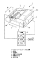
図1及び図2において、ヘッドアップディスプレイ(HUD)装置1は、表示源2と、反射部材3と、車幅方向移動手段4と、操作部5と、制御部6と、を有し、それらを収容ケース10に収容して構成している。収容ケース10は、例えば合成樹脂部材、金属部材等によって略箱状に形成されており、表示光Lを車両のウインドシールド101に向けて出射するための開口11を有している。そして、開口11は、表示源2の表示面に対応した形状(図1中では略方形状)、大きさで形成されている。
[Example 1]
1 and 2, a head-up display (HUD) device 1 includes a
HUD装置1は、図2に示すように、車両のウインドシールド(ウインドシールドガラス)101に対向する対向部材に相当するインストルメントパネル(以下、インパネともいう)102内に設けられている。 As shown in FIG. 2, the HUD device 1 is provided in an instrument panel (hereinafter also referred to as an instrument panel) 102 corresponding to a facing member that faces a windshield (windshield glass) 101 of a vehicle.
HUD装置1の表示光Lは、インパネ102の開口部103からウインドシールド101の投射エリアE上に投射された表示情報(画像等)の虚像Sとして、運転者のアイポイントEPから視認される。そして、HUD装置1は、その虚像Sと、アイポイントEPからウインドシールド101を透して視認される車両の前景とを運転者に重畳視認させる。
The display light L of the HUD device 1 is viewed from the driver's eye point EP as a virtual image S of display information (image or the like) projected on the projection area E of the
HUD装置1は、公知であるように、アイポイントEPがアイレンジER内を移動しても虚像Sが視認できることを保障するため、投射エリアEに対する表示光Lの投射位置を車両の上下方向に調整する上下方向調整機構を有している。なお、上下方向調整機構については、本発明と直接関係ないため、詳細な説明を省略するが、反射部材3における表示光Lの反射角を調整するものである。また、本実施形態では、投射エリアEをウインドシールド101の内面とした場合について説明するが、本発明はこれに限定するものではなく、公知であるコンバイナ等の表面を投射エリアEとするなど種々異なる実施形態とすることができる。
As is known, the HUD device 1 sets the projection position of the display light L with respect to the projection area E in the vertical direction of the vehicle in order to ensure that the virtual image S can be visually recognized even when the eye point EP moves within the eye range ER. It has a vertical adjustment mechanism to adjust. The vertical adjustment mechanism is not directly related to the present invention, and thus detailed description thereof is omitted, but the reflection angle of the display light L on the
表示源2は、自発光デバイス(例えば、FE〔フィールドエミッション〕ディスプレイ、蛍光表示管、EL〔エレクトロルミネッセンス〕ディスプレイ等)や、バックライト付きの液晶ディスプレイ等が用いられる。表示源2は、ウインドシールド101に対向する対向部材であるインパネ102に形成された前記車幅方向に延びるスリット状の開口部103から、表示光Lを投射エリアEに向けて出射するようにインパネ102内に設けられている。表示源2は、制御部6の制御によって要求された表示情報等を表示することで、その表示光Lを出射している。なお、表示情報の一例としては、画像データ、誘導データ、指標データ等の任意のデータを有して構成している。
As the
反射部材3は、反射ミラー、拡大ミラー等が用いられ、表示源2に表示された表示情報の表示光Lを、車両のウインドシールド101の投影エリアEに向けて反射する。つまり、表示源2と反射部材3とは、収容ケース10内で対向するように配置されている。なお、本最良の形態では、説明を簡単化するために、1つの反射部材3を設ける場合について説明するが、本発明はこれに限定するものではなく、複数の反射部材3を設けて表示光Lを複数回反射させる、反射部材3を用いずに表示光Lをウインドシールド101に直接投射するなど種々異なる実施形態とすることができる。
The reflecting
車幅方向移動手段4は、図3等に示すように、ベース部材41と、駆動部42と、伝達部43と、ガイド部44と、移動量検出部45と、を有し、それらを収容ケース10内に収容して構成している。
As shown in FIG. 3 or the like, the vehicle width direction moving means 4 includes a
ベース部材41は、板状に形成され且つ反射部材3が固定される基部41aと、該基部41aの一端側からウインドシールド101に向かって立設し且つ前記反射部材3と対向するように表示源2が固定される第1立設部41bと、該基部41aの他端側からウインドシールド101に向かって立設し且つ伝達部43が上端に形成される第2立設部41cと、を有している。
The
駆動部42は、各種モータ等が用いられ、制御部6と電気的に接続されている。駆動部42は、回動自在の出力部には歯車42aが設けられており、制御部6の制御によって歯車42aが任意の回動方向に回動する構造となっている。そして、伝達部43は、その歯車42aにとかみ合う複数の歯を有し、そのかみ合わせによって駆動部42の動力をベース部材41に伝達する構造となっている。
The
ガイド部44は、収容ケース10の底板の内面に、車両の車幅方向に延びるように設けられた複数(図1,3中では一対)のレール44aと、各レール44aに沿った移動が可能なように係合する複数の凸部44bと、を有している。そして、移動量検出部45は、可変抵抗、ホールIC、フォトセンサ等が任意に用いられ、制御部6と電気的に接続されている。移動量検出部45は、ベース部材41の移動量に応じた移動量信号を制御部6に出力する。
The
このように構成した車幅方向移動手段4は、駆動部42の出力が伝達部43を介してベース部材41に伝達されることで、ガイド部44に沿ってベース部材41が車幅方向Wにスライドすることになる。つまり、駆動部42の歯車42aの回動方向に応じて、ベース部材41を車幅方向Wにおける一方向又は他方向に移動させることができる。そして、その移動可能範囲が、虚像Sの車幅方向Wにおける移動可能範囲となる。
In the vehicle width direction moving means 4 configured in this way, the output of the
操作部5は、制御部6と電気的に接続されており、例えば車幅方向Wにおける移動方向、移動量などを運転者に選択させる複数の操作スイッチ(図示せず)を有している。操作部5は、それらの操作スイッチに対する操作に応じた操作信号を制御部6に出力する。操作部5は、車両のフロントパネル等に運転者が操作可能に設けられている。
The
制御部6は、公知であるCPU(中央処理装置)61、ROM(読み出し専用メモリー)62、及びRAM(随時書き込み読み出しメモリー)63を含むマイクロコンピュータから構成されている。ROM62は、上述した車幅方向移動手段4の車幅方向における移動等を制御するための移動制御処理プログラム等の各種データを記憶している。RAM63は、CPU61が各種の処理を実行する上において必要なデータ等が適宜記憶される。
The
また、表示源2の表示情報をウインドシールド101上の投射エリアEに投射する場合、ウインドシールド101が非平面であることから、図4(a)に示すように、投射エリアEの左側寄り又は右側寄りの虚像Sは、歪んだ形状で運転者等によって視認される。そのため、図4(b)に示すように、虚像Sの歪みを補正するための補正情報を、虚像Sの表示位置、つまり車幅方向移動手段4の移動位置に対応させてROM62等に予め複数記憶している。そして、補正情報の一例としては、虚像2を車幅方向に直線的に移動させるように、表示源2に表示する表示情報を変形させるための補正データを有するなど種々異なるデータ構造とすることができる。
In addition, when the display information of the
次に、上述したCPU61が実行する移動制御処理の一例を、図5に示すフローチャートを参照して以下に説明する。なお、この処理は、表示源2の表示開始に応じて起動され、そして、電源断、終了要求の発生等に応じて強制終了されることを前提としている。
Next, an example of the movement control process executed by the
CPU61によって上記移動制御処理プログラムが実行されると、ステップS11において、操作部5からの操作信号に基づいて、車幅方向Wの操作に対応した操作が行われたか否かが判定される。操作されていないと判定した場合(S11でN)、この判定処理を繰り返すことで、運転者等による操作を待つ。一方、操作されたと判定した場合(S11でY)、ステップS12に進む。
When the movement control processing program is executed by the
ステップS12において、操作部5からの操作信号に基づいて、車幅方向Wにおける表示情報(虚像S)を移動すべき選択位置が検出され、その移動方向、移動量等を示す選択位置情報がRAM63に記憶され、ステップS13において、その選択位置情報に基づいて駆動制御プログラムを実行することで、車幅方向移動手段4の駆動部42が制御されて収容ケース10が車幅方向Wにおける所望の選択位置まで移動され、その後ステップS14に進む。
In step S12, based on an operation signal from the
ステップS14において、ROM62に記憶された複数の補正情報の中から、上記選択位置に対応した補正情報が抽出され、該補正情報が予め定められた記憶領域にセットされることで、同時に動作している表示制御処理によって表示すべき表示情報がその補正情報に基づいて補正されて表示源2に表示され、その後ステップS11に戻り、一連の処理が繰り返される。
In step S14, the correction information corresponding to the selected position is extracted from the plurality of correction information stored in the
以上説明したように、CPU61は図5に示す移動制御処理を実行することで、CPU61が請求項中の移動制御手段として機能することになる。
As described above, the
次に、上述した構成のHUD装置1の動作(作用)の一例を、図4の図面等を参照して以下に説明する。 Next, an example of the operation (action) of the HUD device 1 configured as described above will be described below with reference to the drawing of FIG.
HUD装置1は、運転者からの要求等に応じて起動されると、表示源2に表示情報を表示することで、運転者によって所望の調整角度に調整された反射部材3で反射した表示光Lを、ウインドシールド101の投射エリアEに投射する。これにより、運転者は表示情報の虚像Sと、アイポイントEPからウインドシールド101を透して視認される車両の前景とを重畳視認する。
When the HUD device 1 is activated in response to a request from the driver, the display light is displayed on the
長時間の運転等によって運転者の姿勢が変化して、運転者による虚像Sの視認性が低下すると、運転者は虚像Sの表示位置を車幅方向Wに移動させるために、操作部5に対して所定の操作を行う。これにより、HUD装置1は、その操作から移動させるべき選択位置(表示位置)を検出し、車幅方向移動手段4を制御することで、その選択位置まで収容ケース10内で車幅方向移動手段4を車幅方向Wに移動させる。その結果、収容ケース10に収容された表示源2からの表示光Lは、投射エリアEの車幅方向Wにおける任意の方向に移動するため、虚像Sは車幅方向Wに移動することになる。よって、運転者の姿勢に適した表示位置に虚像Sが表示されるため、運転者による虚像Sの視認性を向上することができる。
When the driver's posture changes due to driving for a long time or the like and the visibility of the virtual image S by the driver is reduced, the driver moves the display position of the virtual image S in the vehicle width direction W in order to move to the
以上説明したHUD装置1によれば、車両の上下方向に調整した虚像Sでも、運転者の姿勢の変化等によって視認しづらくなった場合等に、その虚像Sを車幅方向Wに移動させて調整できるようにしたことから、同一の運転者に対する運転中の視認性の低下を防止することができる。従って、運転中の運転者に対するサービス及び視認性の向上を図ることができるため、HUD装置1の商品価値の向上に貢献することができる。 According to the HUD device 1 described above, even when the virtual image S adjusted in the vertical direction of the vehicle is difficult to visually recognize due to a change in the driver's posture, the virtual image S is moved in the vehicle width direction W. Since the adjustment can be made, it is possible to prevent the visibility of the same driver from being lowered during driving. Therefore, it is possible to improve the service and visibility for the driving driver, and thus contribute to the improvement of the commercial value of the HUD device 1.
[実施例2]
次に、上述した実施例1では、収容ケース10内の部品のみを移動させる実施形態を説明したが、実施例2では、収容ケース10を車幅方向Wに移動させる場合について説明する。なお、実施例1と共通する部分には同一の符号を付し、重複する説明は省略する。
[Example 2]
Next, in the first embodiment described above, the embodiment in which only the components in the
図7及び図8において、ヘッドアップディスプレイ(HUD)装置1は、表示源2と、反射部材3と、車幅方向移動手段4と、操作部5と、制御部6と、を有している。HUD装置1は、反射部材3を収容ケース10内に収容し、該反射部材3に上記反射光Lが投射可能なように表示源2を収容ケース10に設けている。なお、表示源2の収容ケース10に対する取り付け形態については、その外部に突出させる場合について説明するが、上述したように収容ケース10内に収容する実施形態とすることもできる。
7 and 8, the head-up display (HUD) device 1 includes a
車幅方向移動手段4は、駆動部42と、伝達部43と、ガイド部44と、移動量検出部45と、を有し、それらを収容ケース10に設けている。つまり、実施例2では、実施例1のベース部材41として収容ケース10を機能させている。
The vehicle width direction moving means 4 includes a
駆動部42は、収容ケース10の外側の所定位置に位置付けられて固定されている。伝達部43は、収容ケース10の端部上面から突出する凸部12の上端部に形成されている。また、ガイド部44は、インパネ102内の補強部材等にレール44a、また、収容ケース10の底板の外側表面に凸部44bをそれぞれ設けて構成している。
The
さらに、収容ケース10は、図7に示すように、インパネ102の開口部103から収容ケース1の開口11のみが露出するように開口部103を遮蔽し且つ収容ケース10と一体に形成された遮蔽部材12と、遮蔽部材12を車幅方向Wに移動自在に保持し且つインパネ102の開口部103の周縁に形成された保持部13と、を有している。
Further, as shown in FIG. 7, the
このように構成したHUD装置1によれば、車幅方向移動手段4の駆動部42の出力が伝達部43を介して収容ケース10に伝達されることで、ガイド部44に沿って収容ケース10が車幅方向Wにスライドすることになる。そして、収容ケース10が車幅方向Wに移動しても、遮蔽部材12も収容ケース10と共に移動するため、インパネ102の開口部103からは収容ケース10の開口11と遮蔽部材12が露出することになる。よって、インパネ102の内部が目視されることを防止できる。また、収容ケース10の移動可能範囲が、虚像Sの車幅方向Wにおける移動可能範囲となる。即ち、実施例2では、車幅方向移動手段4が虚像Sを車幅方向Wに移動させるために、収容ケース10を車幅方向Wに移動させる手段となっている。
According to the HUD device 1 configured as described above, the output of the
次に、実施例2に係る構成のHUD装置1の動作(作用)の一例を、図6及び図7を参照して以下に説明する。 Next, an example of the operation (action) of the HUD device 1 having the configuration according to the second embodiment will be described below with reference to FIGS. 6 and 7.
HUD装置1は、運転者からの要求等に応じて起動されると、表示源2に表示情報を表示することで、運転者によって所望の調整角度に調整された反射部材3で反射した表示光Lを、ウインドシールド101の投射エリアEに投射する。これにより、運転者は表示情報の虚像Sと、アイポイントEPからウインドシールド101を透して視認される車両の前景とを重畳視認する。
When the HUD device 1 is activated in response to a request from the driver, the display light is displayed on the
長時間の運転等によって運転者の姿勢が変化して、運転者による虚像Sの視認性が低下すると、運転者は虚像Sの表示位置を車幅方向Wに移動させるために、操作部5に対して所定の操作を行う。これにより、HUD装置1は、その操作から移動させるべき選択位置(表示位置)を検出し、車幅方向移動手段4を制御することで、その選択位置までインパネ102内の収容ケース10を車幅方向Wに移動させる。その結果、収容ケース10に収容された表示源2からの表示光Lは、投射エリアEの車幅方向Wにおける任意の方向に移動するため、虚像Sは車幅方向Wに移動することになる。よって、運転者の姿勢に適した表示位置に虚像Sが表示されるため、運転者による虚像Sの視認性を向上することができる。
When the driver's posture changes due to driving for a long time or the like and the visibility of the virtual image S by the driver is reduced, the driver moves the display position of the virtual image S in the vehicle width direction W in order to move to the
以上説明したHUD装置1によれば、車両の上下方向に調整した虚像Sでも、運転者の姿勢の変化等によって視認しづらくなった場合等に、その虚像Sを車幅方向Wに移動させて調整できるようにしたことから、同一の運転者に対する運転中の視認性の低下を防止することができる。従って、運転中の運転者に対するサービス及び視認性の向上を図ることができるため、HUD装置1の商品価値の向上に貢献することができる。 According to the HUD device 1 described above, even when the virtual image S adjusted in the vertical direction of the vehicle is difficult to visually recognize due to a change in the driver's posture, the virtual image S is moved in the vehicle width direction W. Since the adjustment can be made, it is possible to prevent the visibility of the same driver from being lowered during driving. Therefore, it is possible to improve the service and visibility for the driving driver, and thus contribute to the improvement of the commercial value of the HUD device 1.
また、表示源2を収容した収容ケース10を車幅方向Wに移動させるようにしたことから、表示源2を移動させる必要がなく、表示光Lの投射エリアEに至る光路の変更が必要ないため、収容ケース10の大型化を防止することができる。
In addition, since the
さらに、虚像Sを車幅方向Wに移動させるためにインパネ102の開口部103をスリット状に形成しても、遮蔽部材12によって収容ケース10の開口11のみが開口部103から露出するようにしたことから、開口部103を大型化することができるため、虚像Sの車幅方向Wへの十分な移動量を確保することが可能となり、より一層の視認性向上に貢献することができる。
Furthermore, even if the
[実施例3]
次に、インパネ102内に横幅の広いHUD装置1を収容できない、又は、インパネ102内の車幅方向WにHUD装置1を移動させるスペースを確保できない場合は、HUD装置1を以下のように構成することで対応できる。なお、実施例1,2と共通する部分には同一の符号を付し、重複する説明は省略する。
[Example 3]
Next, when the HUD device 1 having a wide width cannot be accommodated in the
図8において、ヘッドアップディスプレイ(HUD)装置1は、前記表示源2と、反射部材3と、車幅方向移動手段4と、前記操作部5と、前記制御部6と、を有し、それらを前記収容ケース10に収容して構成している。
In FIG. 8, a head-up display (HUD) device 1 includes the
反射部材3は、前記表示源2との対向距離が変化するように前記車両の前後方向Fに移動される第1反射部材31と、第1反射部材31で反射した前記表示光Lを前記投射エリアEに反射し、且つ、前記第1反射部材31の前記前後方向Fへの移動量に応じて、前記表示光Lが異なる前記投射エリアEの車幅方向Wにずれるように設けられた第2反射部材32と、を有して構成している。
The reflecting
車幅方向移動手段4は、図8に示すように、ベース部材41と、駆動部42と、ガイド部44と、前記移動量検出部45(図示せず)と、を有し、それらを収容前記ケース10内に収容して構成している。
As shown in FIG. 8, the vehicle width direction moving means 4 includes a
ベース部材41は、板状に形成されている。ベース部材41は、その上面からウインドシールド101に立設し且つ第1反射部材を固定する一対の固定部41dを有している。そして、駆動部42は、ベース部材41に固定されている。駆動部42は、各種モータ等が用いられ、前記制御部6と電気的に接続されている。駆動部42は、回動自在の出力部に歯車が設けられており、制御部6の制御によって歯車42aが任意の回動方向に回動する構造となっている。
The
ガイド部44は、ベース部材41の両側に位置付けられ、その表面には螺旋状の溝が形成されている。そして、ガイド部44と駆動部42が螺合させることで、ベース部材41を車両の前後方向Fに移動させている。
The
例えば、第1反射部材31が前後方向Fにおける前方位置P1に位置付けられた場合、第1反射部材31で反射した表示光Lは第2反射部材32の反射ポイントR1で反射し、投射エリアEの車幅方向における左寄りに投射される。そして、第1反射部材31が前後方向Fにおける中央位置P2に位置付けられた場合、第1反射部材31で反射した表示光Lは第2反射部材32の反射ポイントR2で反射し、投射エリアEの車幅方向における中央付近に投射される。そして、第1反射部材31が前後方向Fにおける後方位置P3に位置付けられた場合、第1反射部材31で反射した表示光Lは第2反射部材32の反射ポイントR3で反射し、投射エリアEの車幅方向における左寄りに投射される。
For example, when the first reflecting
このように第2反射部材32は、板状又は断面円弧状のミラー等で形成され、第1反射部材32の位置によって反射ポイントR1〜R3がずれるように、収容ケース10内に配置されている。そして、車幅方向移動手段4が、前記虚像Sを前記車幅方向Wに移動させるために、前記第1反射部材31を前記車両の前後方向Fに前記制御部6の制御によって移動させている。つまり、実施例3では、第1反射部材31の前後方向Fにおける移動可能範囲が、虚像Sの車幅方向Wにおける移動可能範囲となる。
As described above, the second reflecting
このように構成したHUD装置1によれば、車幅方向移動手段4の駆動部42の出力がガイド部44に伝達されることで、ベース部材41が車両の前後方向Fにスライドされることになる。これにより、表示源2と第1反射部材31との対向距離が変化するため、第1反射部材31で反射した表示光Lは、その対向距離に対応した第2反射部材における反射ポイントでウインドシールド102に向かって反射する。即ち、第1反射部材31を前後方向Fに移動されることで、投射エリアEの車幅方向Wに投射ポイントをずらすことができる。
According to the HUD device 1 configured as described above, the output of the
次に、実施例3に係る構成のHUD装置1の動作(作用)の一例を、図2,8等を参照して以下に説明する。 Next, an example of the operation (action) of the HUD device 1 having the configuration according to the third embodiment will be described below with reference to FIGS.
HUD装置1は、運転者からの要求等に応じて起動されると、表示源2に表示情報を表示することで、運転者によって所望の調整角度に調整された反射部材3で反射した表示光Lを、ウインドシールド101の投射エリアEに投射する。これにより、運転者は表示情報の虚像Sと、アイポイントEPからウインドシールド101を透して視認される車両の前景とを重畳視認する。
When the HUD device 1 is activated in response to a request from the driver, the display light is displayed on the
長時間の運転等によって運転者の姿勢が変化して、運転者による虚像Sの視認性が低下すると、運転者は虚像Sの表示位置を車幅方向Wに移動させるために、操作部5に対して所定の操作を行う。これにより、HUD装置1は、その操作から移動させるべき選択位置(表示位置)を検出し、車幅方向移動手段4を制御することで、その選択位置まで第1反射部材31を前後方向Fに移動させる。その結果、収容ケース10に収容された表示源2からの表示光Lは、第2反射部材32によって投射エリアEの車幅方向Wにおける任意の方向にずらされるため、虚像Sは車幅方向Wに移動することになる。よって、運転者の姿勢に適した表示位置に虚像Sが表示されるため、運転者による虚像Sの視認性を向上することができる。
When the driver's posture changes due to driving for a long time or the like and the visibility of the virtual image S by the driver is reduced, the driver moves the display position of the virtual image S in the vehicle width direction W in order to move to the
以上説明したHUD装置1によれば、車両の上下方向に調整した虚像Sでも、運転者の姿勢の変化等によって視認しづらくなった場合等に、その虚像Sを車幅方向Wに移動させて調整できるようにしたことから、同一の運転者に対する運転中の視認性の低下を防止することができる。従って、運転中の運転者に対するサービス及び視認性の向上を図ることができるため、HUD装置1の商品価値の向上に貢献することができる。 According to the HUD device 1 described above, even when the virtual image S adjusted in the vertical direction of the vehicle is difficult to visually recognize due to a change in the driver's posture, the virtual image S is moved in the vehicle width direction W. Since the adjustment can be made, it is possible to prevent the visibility of the same driver from being lowered during driving. Therefore, it is possible to improve the service and visibility for the driving driver, and thus contribute to the improvement of the commercial value of the HUD device 1.
また、第1反射部材31を車両の前後方向Fに移動させることで、第2反射部材32によって虚像Sを車幅方向Wに移動させることが可能な構成としたことから、インストルメントパネル102内の車幅方向Fに十分な収容スペースが確保できない場合でも、虚像Sの車幅方向Wへの移動を可能とすることができる。
In addition, since the first reflecting
このように上述した実施例は本発明の代表的な形態を示したに過ぎず、本発明は、実施形態に限定されるものではない。即ち、本発明の骨子を逸脱しない範囲で種々変形して実施することができる。 As described above, the above-described embodiments are merely representative forms of the present invention, and the present invention is not limited to the embodiments. That is, various modifications can be made without departing from the scope of the present invention.
1 ヘッドアップディスプレイ(HUD)装置
2 表示源
3 反射部材
4 車幅方向移動手段
5 操作部
6 制御部(選択位置検出手段、移動制御手段)
31 第1反射部材
32 第2反射部材
101 ウインドシールド
102 インストルメントパネル(対向部材)
103 開口部
W 車幅方向
DESCRIPTION OF SYMBOLS 1 Head up display (HUD)
31
103 opening W width direction
Claims (4)
前記投射エリア上における前記表示光の投射位置を前記車両の車幅方向に移動させる車幅方向移動手段と、
前記車幅方向における前記虚像を投射すべき選択位置を検出し、その選択位置に前記虚像が移動するように前記車幅方向移動手段の移動を制御する移動制御手段と、
を有することを特徴とするヘッドアップディスプレイ装置。 A foreground of the vehicle that has a display source, projects display light of display information displayed on the display source to a windshield side projection area of the vehicle, and is viewed through the windshield from the eyepoint of the vehicle And a virtual image of display information projected on the projection area, and a head-up display device that superimposes and visually recognizes,
Vehicle width direction moving means for moving the projection position of the display light on the projection area in the vehicle width direction of the vehicle;
A movement control means for detecting a selection position to project the virtual image in the vehicle width direction and controlling movement of the vehicle width direction movement means so that the virtual image moves to the selection position;
A head-up display device comprising:
前記車幅方向移動手段が、前記虚像を前記車幅方向に移動させるために、前記収容ケースを前記車幅方向に移動させる手段であることを特徴とする請求項1に記載のヘッドアップディスプレイ装置。 A storage case for storing the display source;
The head-up display device according to claim 1, wherein the vehicle width direction moving means is means for moving the housing case in the vehicle width direction in order to move the virtual image in the vehicle width direction. .
前記対向部材の開口部から前記収容ケースの開口のみが露出するように前記開口部を遮蔽する遮蔽部材を有することを特徴とする請求項2に記載のヘッドアップディスプレイ装置。 The display source is provided in the facing member so as to emit the display light toward the projection area from a slit-shaped opening extending in the vehicle width direction formed in the facing member facing the windshield. Display source,
The head-up display device according to claim 2, further comprising a shielding member that shields the opening so that only the opening of the housing case is exposed from the opening of the facing member.
前記第1反射部材で反射した前記表示光を前記投射エリアに反射し、且つ、前記第1反射部材の前記前後方向への移動量に応じて、前記表示光が前記投射エリアの車幅方向にずれるように設けられた第2反射部材と、
を有し、
前記車幅方向移動手段が、前記虚像を前記車幅方向に移動させるために、前記第1反射部材を前記車両の前後方向に移動させる手段であることを特徴とする請求項1に記載のヘッドアップディスプレイ装置。 A first reflecting member that is moved in the front-rear direction of the vehicle so that a distance to the display source changes;
The display light reflected by the first reflecting member is reflected to the projection area, and the display light is reflected in the vehicle width direction of the projection area according to the amount of movement of the first reflecting member in the front-rear direction. A second reflecting member provided to be displaced;
Have
2. The head according to claim 1, wherein the vehicle width direction moving means is means for moving the first reflecting member in the front-rear direction of the vehicle in order to move the virtual image in the vehicle width direction. Up display device.
Priority Applications (1)
| Application Number | Priority Date | Filing Date | Title |
|---|---|---|---|
| JP2008330775A JP5336169B2 (en) | 2008-12-25 | 2008-12-25 | Head-up display device |
Applications Claiming Priority (1)
| Application Number | Priority Date | Filing Date | Title |
|---|---|---|---|
| JP2008330775A JP5336169B2 (en) | 2008-12-25 | 2008-12-25 | Head-up display device |
Publications (2)
| Publication Number | Publication Date |
|---|---|
| JP2010149733A true JP2010149733A (en) | 2010-07-08 |
| JP5336169B2 JP5336169B2 (en) | 2013-11-06 |
Family
ID=42569317
Family Applications (1)
| Application Number | Title | Priority Date | Filing Date |
|---|---|---|---|
| JP2008330775A Active JP5336169B2 (en) | 2008-12-25 | 2008-12-25 | Head-up display device |
Country Status (1)
| Country | Link |
|---|---|
| JP (1) | JP5336169B2 (en) |
Cited By (6)
| Publication number | Priority date | Publication date | Assignee | Title |
|---|---|---|---|---|
| CN102555928A (en) * | 2012-01-11 | 2012-07-11 | 河南科技大学 | Novel protector for head-up display |
| JP2016075881A (en) * | 2014-10-07 | 2016-05-12 | 株式会社リコー | Image display device |
| WO2018149414A1 (en) * | 2017-02-17 | 2018-08-23 | 矽创电子股份有限公司 | Optical imaging device capable of positioning projection |
| WO2018193708A1 (en) * | 2017-04-19 | 2018-10-25 | マクセル株式会社 | Head-up display device and display control method therefor |
| WO2021015171A1 (en) * | 2019-07-25 | 2021-01-28 | 株式会社小糸製作所 | Head-up display |
| CN114816291A (en) * | 2021-01-27 | 2022-07-29 | 本田技研工业株式会社 | Head-up display control system and head-up display method |
Citations (8)
| Publication number | Priority date | Publication date | Assignee | Title |
|---|---|---|---|---|
| JPH0215524U (en) * | 1988-07-15 | 1990-01-31 | ||
| JPH0258786U (en) * | 1988-10-21 | 1990-04-26 | ||
| JPH0333726U (en) * | 1989-08-04 | 1991-04-03 | ||
| JPH0333725U (en) * | 1989-08-04 | 1991-04-03 | ||
| JPH0333727U (en) * | 1989-08-04 | 1991-04-03 | ||
| JPH0894756A (en) * | 1994-09-21 | 1996-04-12 | Nippondenso Co Ltd | Device for displaying distance between cars, and target cruise |
| JP2002019491A (en) * | 2000-07-11 | 2002-01-23 | Mazda Motor Corp | Display device of vehicle |
| JP2002052955A (en) * | 2000-08-10 | 2002-02-19 | Yazaki Corp | Display device for vehicle |
-
2008
- 2008-12-25 JP JP2008330775A patent/JP5336169B2/en active Active
Patent Citations (8)
| Publication number | Priority date | Publication date | Assignee | Title |
|---|---|---|---|---|
| JPH0215524U (en) * | 1988-07-15 | 1990-01-31 | ||
| JPH0258786U (en) * | 1988-10-21 | 1990-04-26 | ||
| JPH0333726U (en) * | 1989-08-04 | 1991-04-03 | ||
| JPH0333725U (en) * | 1989-08-04 | 1991-04-03 | ||
| JPH0333727U (en) * | 1989-08-04 | 1991-04-03 | ||
| JPH0894756A (en) * | 1994-09-21 | 1996-04-12 | Nippondenso Co Ltd | Device for displaying distance between cars, and target cruise |
| JP2002019491A (en) * | 2000-07-11 | 2002-01-23 | Mazda Motor Corp | Display device of vehicle |
| JP2002052955A (en) * | 2000-08-10 | 2002-02-19 | Yazaki Corp | Display device for vehicle |
Cited By (15)
| Publication number | Priority date | Publication date | Assignee | Title |
|---|---|---|---|---|
| CN102555928B (en) * | 2012-01-11 | 2014-03-26 | 河南科技大学 | Novel protector for head-up display |
| CN102555928A (en) * | 2012-01-11 | 2012-07-11 | 河南科技大学 | Novel protector for head-up display |
| JP2016075881A (en) * | 2014-10-07 | 2016-05-12 | 株式会社リコー | Image display device |
| JP2020510861A (en) * | 2017-02-17 | 2020-04-09 | シトロニックス テクノロジー コーポレーション | Optical imaging device with projection alignment |
| WO2018149414A1 (en) * | 2017-02-17 | 2018-08-23 | 矽创电子股份有限公司 | Optical imaging device capable of positioning projection |
| CN108459414A (en) * | 2017-02-17 | 2018-08-28 | 矽创电子股份有限公司 | The optical imaging device of tool projection positioning |
| JP7114612B2 (en) | 2017-02-17 | 2022-08-08 | シトロニックス テクノロジー コーポレーション | Optical imaging device with projection alignment |
| CN108459414B (en) * | 2017-02-17 | 2021-08-27 | 矽创电子股份有限公司 | Optical imaging device with projection positioning |
| CN110573369A (en) * | 2017-04-19 | 2019-12-13 | 麦克赛尔株式会社 | Head-up display device and display control method thereof |
| JPWO2018193708A1 (en) * | 2017-04-19 | 2019-12-19 | マクセル株式会社 | Head-up display device and display control method thereof |
| US11241960B2 (en) | 2017-04-19 | 2022-02-08 | Maxell, Ltd. | Head up display apparatus and display control method thereof |
| CN110573369B (en) * | 2017-04-19 | 2022-05-17 | 麦克赛尔株式会社 | Head-up display device and display control method thereof |
| WO2018193708A1 (en) * | 2017-04-19 | 2018-10-25 | マクセル株式会社 | Head-up display device and display control method therefor |
| WO2021015171A1 (en) * | 2019-07-25 | 2021-01-28 | 株式会社小糸製作所 | Head-up display |
| CN114816291A (en) * | 2021-01-27 | 2022-07-29 | 本田技研工业株式会社 | Head-up display control system and head-up display method |
Also Published As
| Publication number | Publication date |
|---|---|
| JP5336169B2 (en) | 2013-11-06 |
Similar Documents
| Publication | Publication Date | Title |
|---|---|---|
| JP5286243B2 (en) | Head-up display device | |
| JP6265701B2 (en) | Head-up display device | |
| JP6160398B2 (en) | Head-up display device | |
| JP6098486B2 (en) | Vehicle display device | |
| JP5336169B2 (en) | Head-up display device | |
| JP4490605B2 (en) | In-vehicle head-up display device | |
| JP6693474B2 (en) | Head up display device | |
| JP6154227B2 (en) | Display unit | |
| JP2006106254A (en) | Head-up display for vehicle | |
| JP2007086226A (en) | Head-up display apparatus | |
| JP5316430B2 (en) | Vehicular head-up display device and manufacturing method thereof | |
| US12055713B2 (en) | Head-up display system | |
| JP6209378B2 (en) | Display unit | |
| CN113741031A (en) | Vehicle-mounted display device | |
| JP2006062501A (en) | Head up display | |
| JP2007022174A (en) | On-board display system | |
| JP2006069473A (en) | Head-up display | |
| JP2006015941A (en) | Display device for vehicle | |
| JP2015112974A (en) | Head-up display | |
| JP2006248322A (en) | Display device for vehicle | |
| JPWO2019102731A1 (en) | Head-up display device | |
| JP6205158B2 (en) | Head-up display device | |
| JP6014500B2 (en) | Head-up display device | |
| JP2006065092A (en) | Head-up display | |
| JP6014501B2 (en) | Head-up display device |
Legal Events
| Date | Code | Title | Description |
|---|---|---|---|
| A621 | Written request for application examination |
Free format text: JAPANESE INTERMEDIATE CODE: A621 Effective date: 20111101 |
|
| A977 | Report on retrieval |
Free format text: JAPANESE INTERMEDIATE CODE: A971007 Effective date: 20121015 |
|
| A131 | Notification of reasons for refusal |
Free format text: JAPANESE INTERMEDIATE CODE: A131 Effective date: 20121023 |
|
| A521 | Request for written amendment filed |
Free format text: JAPANESE INTERMEDIATE CODE: A523 Effective date: 20121225 |
|
| A02 | Decision of refusal |
Free format text: JAPANESE INTERMEDIATE CODE: A02 Effective date: 20130319 |
|
| A521 | Request for written amendment filed |
Free format text: JAPANESE INTERMEDIATE CODE: A523 Effective date: 20130611 |
|
| A911 | Transfer to examiner for re-examination before appeal (zenchi) |
Free format text: JAPANESE INTERMEDIATE CODE: A911 Effective date: 20130618 |
|
| TRDD | Decision of grant or rejection written | ||
| A01 | Written decision to grant a patent or to grant a registration (utility model) |
Free format text: JAPANESE INTERMEDIATE CODE: A01 Effective date: 20130709 |
|
| A61 | First payment of annual fees (during grant procedure) |
Free format text: JAPANESE INTERMEDIATE CODE: A61 Effective date: 20130801 |
|
| R150 | Certificate of patent or registration of utility model |
Ref document number: 5336169 Country of ref document: JP Free format text: JAPANESE INTERMEDIATE CODE: R150 Free format text: JAPANESE INTERMEDIATE CODE: R150 |
|
| R250 | Receipt of annual fees |
Free format text: JAPANESE INTERMEDIATE CODE: R250 |
|
| R250 | Receipt of annual fees |
Free format text: JAPANESE INTERMEDIATE CODE: R250 |
|
| R250 | Receipt of annual fees |
Free format text: JAPANESE INTERMEDIATE CODE: R250 |
|
| R250 | Receipt of annual fees |
Free format text: JAPANESE INTERMEDIATE CODE: R250 |
|
| R250 | Receipt of annual fees |
Free format text: JAPANESE INTERMEDIATE CODE: R250 |
|
| R250 | Receipt of annual fees |
Free format text: JAPANESE INTERMEDIATE CODE: R250 |
|
| R250 | Receipt of annual fees |
Free format text: JAPANESE INTERMEDIATE CODE: R250 |
|
| S531 | Written request for registration of change of domicile |
Free format text: JAPANESE INTERMEDIATE CODE: R313531 |
|
| R350 | Written notification of registration of transfer |
Free format text: JAPANESE INTERMEDIATE CODE: R350 |
|
| R250 | Receipt of annual fees |
Free format text: JAPANESE INTERMEDIATE CODE: R250 |