JP2010147587A - Imaging device and imaging method - Google Patents
Imaging device and imaging method Download PDFInfo
- Publication number
- JP2010147587A JP2010147587A JP2008319969A JP2008319969A JP2010147587A JP 2010147587 A JP2010147587 A JP 2010147587A JP 2008319969 A JP2008319969 A JP 2008319969A JP 2008319969 A JP2008319969 A JP 2008319969A JP 2010147587 A JP2010147587 A JP 2010147587A
- Authority
- JP
- Japan
- Prior art keywords
- imaging
- image data
- image processing
- shooting
- voice
- Prior art date
- Legal status (The legal status is an assumption and is not a legal conclusion. Google has not performed a legal analysis and makes no representation as to the accuracy of the status listed.)
- Granted
Links
Images

Abstract
Description
本発明は撮像装置及び撮像方法に関し、特に、撮影時の雰囲気や臨場感を反映した画像を撮影するために用いて好適な技術に関する。 The present invention relates to an image pickup apparatus and an image pickup method, and more particularly to a technique suitable for use in taking an image reflecting an atmosphere and a sense of reality at the time of shooting.
従来、撮影時における撮影者の感情を撮影画像に反映させることを目的として、撮影者の体温、発汗、グリップ圧力等の状態を検出する感情検出センサ、及び撮影時の位置・外気温・外湿度を検出する環境検出センサを有している。そして、各々の検出センサの検出値に応じて取得画像の画像処理パラメータを変更する技術が特許文献1に開示されている。
Conventionally, an emotion detection sensor for detecting the photographer's body temperature, sweating, grip pressure, etc., and the position / external temperature / external humidity at the time of photographing for the purpose of reflecting the photographer's emotion at the time of photographing in the photographed image. Has an environment detection sensor for detecting
また、「撮影時の雰囲気」を撮影画像から感じ取れることを目的として、音声入力可能なカメラにおいて、入力された音声の音量や抑揚を分析する。そして、分析結果に応じて最適な形式の文字画像に変換し、被写体像と合成した撮影画像を取得する技術が特許文献2に開示されている。
In addition, in order to make the “atmosphere at the time of photographing” feel from a photographed image, the volume and inflection of the inputted voice are analyzed in a camera capable of voice input.
一般的に、撮像装置は、撮像光学系を介して結像された光学像を電気信号に変換して画像情報を取得し、記録媒体に記録したり、表示装置に表示したりするものである。いわば、撮影者の視覚情報を記録保存できるようにした装置である。 In general, an imaging apparatus converts an optical image formed through an imaging optical system into an electrical signal to acquire image information, and records the information on a recording medium or displays it on a display device. . In other words, it is a device that can record and store the photographer's visual information.
しかし、実際には撮影者は視覚情報のみならず、無意識にも聴覚・触覚等の他の感覚器官から得られた情報を加味し、撮影時の「映像」を記憶して保存する。このため、撮影後に時間を経過してから撮影画像を見返すと、自分の記憶に保存された「映像」とは異なるように感じることがある。 However, in reality, the photographer stores not only visual information but also information obtained from other sensory organs such as auditory and tactile sensation, and stores and stores the “video” at the time of photographing. For this reason, when the photographed image is looked back after a lapse of time after photographing, it may feel different from the “video” stored in its own memory.
これに対して、前記特許文献1にて開示されている技術では、外気温・外湿度センサにより撮影時の触覚、特に温覚・湿覚を検出し画像に反映させることができ、より臨場感のある画像を取得することができる。しかし、聴覚情報には触れられていない。
On the other hand, in the technique disclosed in
一方で、前記特許文献2にて開示されている技術では、聴覚情報を文字という形で撮影画像と合成することで、撮影時の雰囲気を演出できるようにしている。しかし、文字で表現するという形は、臨場感のある映像を記録したいという本来の撮影目的とは若干異なってしまう問題点があった。
On the other hand, in the technique disclosed in
本発明は前述の問題点に鑑み、撮影時の聴覚から得られる情感を撮影画像に表現できるようにすることを目的としている。 In view of the above-described problems, an object of the present invention is to make it possible to express a feeling obtained from hearing at the time of shooting in a shot image.
本発明の撮像装置は、被写体を撮影して静止画像データまたは動画像データを生成する撮像手段と、前記撮像手段によって生成された静止画像データまたは動画像データに所定の画像処理を施す画像処理手段と、前記撮像手段が前記被写体を撮影する時に音声信号を取得する音声入力手段と、前記音声入力手段によって取得された音声信号の特徴量を分析する音声分析処理手段と、前記画像処理手段が前記静止画像データまたは動画像データに所定の画像処理を施すために用いる画像処理パラメータを、前記音声分析処理手段によって分析された音声信号の特徴量に基づいて制御するシステム制御手段とを有することを特徴とする。 An imaging apparatus according to the present invention includes an imaging unit that captures a subject and generates still image data or moving image data, and an image processing unit that performs predetermined image processing on the still image data or moving image data generated by the imaging unit. Voice input means for acquiring a voice signal when the imaging means captures the subject, voice analysis processing means for analyzing a feature amount of the voice signal acquired by the voice input means, and the image processing means System control means for controlling an image processing parameter used for performing predetermined image processing on still image data or moving image data based on a feature amount of an audio signal analyzed by the audio analysis processing means. And
本発明の撮像方法は、被写体を撮影して静止画像データまたは動画像データを生成する撮像工程と、前記撮像工程において生成された静止画像データまたは動画像データに所定の画像処理を施す画像処理工程と、前記撮像工程において前記被写体を撮影する時に音声信号を取得する音声入力工程と、前記音声入力工程において取得された音声信号の特徴量を分析する音声分析処理工程と、前記画像処理工程において前記静止画像データまたは動画像データに所定の画像処理を施すために用いる画像処理パラメータを、前記音声分析処理工程において分析された音声信号の特徴量に基づいて制御するシステム制御工程とを有することを特徴とする。 The imaging method of the present invention includes an imaging step of capturing a subject to generate still image data or moving image data, and an image processing step of performing predetermined image processing on the still image data or moving image data generated in the imaging step. A voice input step of acquiring a voice signal when photographing the subject in the imaging step, a voice analysis processing step of analyzing a feature amount of the voice signal acquired in the voice input step, and the image processing step. A system control step of controlling image processing parameters used for performing predetermined image processing on still image data or moving image data based on a feature amount of an audio signal analyzed in the audio analysis processing step. And
本発明のコンピュータプログラムは、被写体を撮影して静止画像データまたは動画像データを生成する撮像工程と、前記撮像工程において生成された静止画像データまたは動画像データに所定の画像処理を施す画像処理工程と、前記撮像工程において前記被写体を撮影する時に音声信号を取得する音声入力工程と、前記音声入力工程において取得された音声信号の特徴量を分析する音声分析処理工程と、前記画像処理工程において前記静止画像データまたは動画像データに所定の画像処理を施すために用いる画像処理パラメータを、前記音声分析処理工程において分析された音声信号の特徴量に基づいて制御するシステム制御工程とを有する撮像方法をコンピュータに実行させることを特徴とする。 The computer program of the present invention includes an imaging process for capturing a subject to generate still image data or moving image data, and an image processing process for performing predetermined image processing on the still image data or moving image data generated in the imaging process. A voice input step of acquiring a voice signal when photographing the subject in the imaging step, a voice analysis processing step of analyzing a feature amount of the voice signal acquired in the voice input step, and the image processing step. A system control step of controlling an image processing parameter used for performing predetermined image processing on still image data or moving image data based on a feature amount of an audio signal analyzed in the audio analysis processing step; The computer is executed.
本発明によれば、撮影時の聴覚から得られる情感を撮影画像に表現することが可能となり、より臨場感のある撮影画像を得ることができる。 According to the present invention, it is possible to express a feeling obtained from hearing at the time of photographing in a photographed image, and a photographed image with a more realistic feeling can be obtained.
(第1の実施形態)
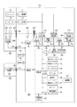
図1は、本発明の第1の実施形態の形態を示し、撮像装置の構成例を示すブロック図である。
図1において、100は撮像装置である。121はレンズユニット200より、図示されていない被写体の光学像を撮影レンズ210から、絞り211、レンズマウント102及び202、シャッター144を含む撮像光学系を介して結像された光学像を電気信号に変換する撮像素子である。
(First embodiment)
FIG. 1 is a block diagram illustrating a configuration example of an imaging apparatus according to the first exemplary embodiment of the present invention.
In FIG. 1,
122は撮像素子121から出力されるアナログ信号出力をデジタル信号に変換し、デジタルの静止画像データまたは動画像データを生成するA/D変換部である。A/D変換部122においてA/D変換されたデジタル信号は、メモリ制御部124及びシステム制御部120により制御され、メモリ127に格納される。
123は画像処理部であり、デジタル信号のデータ或いはメモリ制御部124から読み出されたデータに対して所定の画素補間処理や色変換処理を行う。画像処理部123は適応離散コサイン変換(ADCT)等により画像データを圧縮伸長する圧縮・伸長回路も備えている。
An
また、メモリ127に格納された画像を読み込んで圧縮処理或いは伸長処理を行い、処理を終えたデータをメモリ127に書き込むことも可能である。また、動画撮影モードでは、記録時に、メモリ127に取り込まれている一連の動画像データをMPEG方式等によりデータ圧縮することができる。
It is also possible to read an image stored in the
さらに、画像処理部123では、撮像した画像データを用いて所定の演算処理を行い、コントラスト、明度、彩度、ホワイトバランス、シャープネス等の画像処理を施すことができる。また、TTL(スルーザレンズ)方式のAWB(オートホワイトバランス)処理も行っている。
Further, the
124はメモリ制御部であり、A/D変換部122、画像処理部123、液晶パネル表示部125、外部着脱メモリ部131とメモリ127との間のデータの送受信を制御する。 A/D変換部122においてデジタル化されたデータが画像処理部123、メモリ制御部124を介してメモリ127に書き込まれる。或いは、A/D変換部122から出力されるデジタルデータがメモリ127に直接書き込まれる。
A memory control unit 124 controls transmission / reception of data between the A /
110は液晶ディスプレイ型の表示装置であり、液晶パネル表示部125とバックライト照明部126とから構成される。液晶パネル表示部125は、メモリ127の表示データ用格納領域へ書き込まれたメニュー画面、または外部着脱メモリ部131に格納された画像ファイルを表示することが可能である。
A liquid crystal display type display device 110 includes a liquid crystal panel display unit 125 and a
バックライト照明部126は、液晶パネル表示部125に対して背面照射する光源素子として、LED、有機EL、蛍光管等を用いて構成され、システム制御部120の指示により照明を任意に点灯或いは消灯することが可能である。また、システム制御部120により、電圧駆動方式或いはPWM駆動方式の何れかで光源素子の通電電流を制限することで、表示装置110の表示輝度を調整する調光機能を有する。
The
127は撮影した静止画像及び動画像、再生用表示のための画像及び音声ファイルを格納するためのメモリであり、所定枚数の静止画像や動画像を格納するのに十分な記憶量を備えている。なお、メモリ127はシステム制御部120の作業領域としても使用することが可能である。
128は電気的に消去・記録可能な不揮発性メモリであり、例えばフラッシュメモリやEEPROM等が用いられる。また、不揮発性メモリ128には、撮影状態の保存や、撮像装置100を制御するプログラムが格納されている。
130は接眼検出部であり、赤外発光体及び受光回路で構成されていて、一定間隔で、赤外発光体から赤外光を発光し、被検出物体で反射した赤外光を受光回路で受光し、受光した光量により規定位置に被検出物体があるかどうかを検出する。
131はコンパクトフラッシュ(登録商標)やSDカードといった記録媒体に画像ファイル記録や読み出しを行うための外部着脱メモリ部である。138は電源部であり、電池、電池検出回路、DC/DCコンバータ、通電するブロックを切り替えるスイッチ回路等により構成されており、電池の装着の有無、電池の種類、電池残量の検出を行う。また、検出結果及びシステム制御部120の指示に基づいてDC/DCコンバータを制御し、必要な電圧を必要な期間、各ブロック部へ供給する。
システム制御部120は、撮像装置100の動作状態に伴い、不要なブロックへの電源供給を停止することで、省電力へのパワーマネージメント制御を行っている。その例として、画像再生表示や、メニュー画面表示の場合、カメラ制御ブロックは動作不要のため、カメラ制御部140や測光部142、測距部143、撮像素子121、レンズユニット200、ストロボユニット300への供給電源を遮断する。
The
141は測光部142からの測光情報に基づいて、絞り211を制御するレンズ制御部203と連動しながら、シャッター144を制御するシャッター制御部である。142はAE(自動露出)処理を行うための測光部であり、本実施形態においては、被写体の周辺部の明るさを測るためにも用いられる。
すなわち、撮影レンズ210に入射した光線を、絞り211、レンズマウント202及び102、そして不図示の測光用レンズを介して、測光部142に入射させる。これにより、光学像として結像された被写体の露出状態を測定することができる。また、測光部142は、ストロボユニット300と連携することによりEF(フラッシュ調光)処理機能も有するものである。また、ストロボユニット300は、AF補助光の投光機能、フラッシュ調光機能も有する。
That is, the light beam incident on the photographing
143はAF(オートフォーカス)処理を行うための測距部であり、撮影レンズ210に入射した光線を、絞り211、レンズマウント202及び102、そして不図示の測距用ミラーを介して、測距部143に入射させる。これにより、光学像として結像された画像の合焦状態を測定することができる。上述したように、測距部143及び測光部142を専用に備える構成のため、測距部143及び測光部142を用いてAF(オートフォーカス)処理、AE(自動露出)処理、EF(フラッシュ調光)処理の各処理を行う構成となっている。
140はシャッター制御部141、測光部142、測距部143との送受通信によりカメラとしての一連の動作を制御するカメラ制御部である。カメラ制御部140は、レンズユニット200、ストロボユニット300を制御することも可能である。
A
132、133、134、135、136、及び137は、システム制御部120の各種の動作指示を入力するための操作部を構成するものである。操作部を構成するスイッチやダイアル、タッチパネル、視線検知によるポインティング、音声認識装置等の単数或いは複数の組み合わせで構成されている。
ここで、操作部を構成する操作器具の具体的な説明を行う。
再生スイッチ132は、液晶パネル表示部125に所定の画像データを表示する再生表示モード操作を行うためのスイッチである。外部着脱メモリ部131に格納された画像ファイルを再生表示する場合は、この再生スイッチ132を必ず操作する必要がある。また、すでに再生表示モードで、この操作が行われた場合には、再生表示モードから撮影モードへの切り替えができる。
Here, a specific description of the operation tool constituting the operation unit will be given.
The reproduction switch 132 is a switch for performing a reproduction display mode operation for displaying predetermined image data on the liquid crystal panel display unit 125. When the image file stored in the external
メニュースイッチ133は、 液晶パネル表示部125に各種項目一覧を表示するためのスイッチである。この表示内容としては撮影に関する状態設定、記録媒体のフォーマット、時計の設定、現像パラメータ設定、及びユーザ機能設定(カスタム機能の設定)等がある。 The menu switch 133 is a switch for displaying a list of various items on the liquid crystal panel display unit 125. The display contents include a state setting related to shooting, a recording medium format, a clock setting, a development parameter setting, and a user function setting (custom function setting).
モードダイアル134は、種々の機能撮影モードを切り替え設定するためのスイッチである。本実施形態においては、自動撮影モード、プログラム撮影モード、シャッター速度優先撮影モード、絞り優先撮影モード、マニュアル撮影モード、ポートレート撮影モード、風景撮影モード、スポーツ撮影モード、夜景撮影モード、動画モード等を設定できる。 The mode dial 134 is a switch for switching and setting various function photographing modes. In this embodiment, automatic shooting mode, program shooting mode, shutter speed priority shooting mode, aperture priority shooting mode, manual shooting mode, portrait shooting mode, landscape shooting mode, sports shooting mode, night scene shooting mode, video mode, etc. Can be set.
レリーズスイッチ135は、レリーズボタンの半押し(SW1)及び全押し(SW2)で各々ONとなるスイッチである。半押し状態では、AF(オートフォーカス)処理、AE(自動露出)処理、AWB(オートホワイトバランス)処理、EF(フラッシュ調光)処理等の動作開始を指示する。
The
また、全押し状態では、撮像素子121から読み出したアナログ信号をA/D変換部122によりデジタルの画像データに変換し、メモリ制御部124の制御に従ってメモリ127に書き込む撮像処理を行う。また、画像処理部123やメモリ制御部124で演算を行って映像として見ることができるようにする現像処理を行う。さらに、メモリ127から画像データを読み出し、画像処理部123でさらに圧縮を行い、外部着脱メモリ部131に装着された不図示の記録媒体に画像データを書き込む記録処理を行う、という一連の処理の動作開始を指示する。
In the fully-pressed state, an analog signal read from the
各種ボタンスイッチからなる操作部136は、撮影モード、連写モード、セット、マクロ、ページ送り、フラッシュ設定、メニュー移動、ホワイトバランス選択、撮影画質選択、露出補正、日付/時間設定等を行うことができる。さらに、動画撮影開始及び停止を行う動画撮影スイッチや、上下左右方向スイッチや、再生画像のズーム倍率変更スイッチ、液晶パネル表示部125の画像表示ON/OFFスイッチがある。また、撮影直後に撮影画像データを自動再生するクイックレビューON/OFFスイッチ、再生画像を消去する画像消去スイッチがある。
An
また、JPEG及びMPEG圧縮の各圧縮率と、撮像素子の信号をそのままデジタル化して記録するCCDRAWモードとを選択する圧縮モードスイッチがある。その他、レリーズスイッチ半押し状態でオートフォーカスの合焦状態を保ち続けるワンショットAFモードと連続してオートフォーカス動作を続けるサーボAFモードとを設定するAFモード設定スイッチ等がある。 In addition, there is a compression mode switch for selecting each compression rate of JPEG and MPEG compression and a CCD RAW mode for digitizing and recording the signal of the image sensor as it is. In addition, there is an AF mode setting switch for setting a one-shot AF mode that keeps the autofocus in-focus state when the release switch is half-pressed and a servo AF mode that keeps the autofocus operation continuously.
137は電源スイッチで、撮像装置100の電源オン、電源オフの各モードを切り替え設定することができる。また、撮像装置100に接続されたレンズユニット200、ストロボユニット300、記録媒体等の各種付属装置の電源オン、電源オフの設定も合わせて切り替え設定することができる。タイマー機能139は、時計機能、カレンダー機能、タイマーカウンター機能、アラーム機能があり、スリープモードへの移行時間や、アラーム通知などのシステム管理に用いられる。
Reference numeral 137 denotes a power switch that can switch and set the power-on and power-off modes of the
102及び202は、レンズマウントであり、撮像装置100をレンズユニット200と接続するためのインターフェースである。101及び201は撮像装置100をレンズユニット200と電気的に接続するコネクタであり、カメラ制御部140により制御される。111及び301は、アクセサリシューであり、撮像装置100をストロボユニット300と接続するためのインターフェースである。
レンズ制御部203はレンズユニット200の全体を制御して、動作用の定数、変数、プログラム等を記憶するメモリを備えている。また、レンズユニット200に固有の番号等の識別情報、管理情報、開放絞り値や最小絞り値、焦点距離等の機能情報、現在や過去の各設定値などを保持する不揮発メモリ(図示せず)を備えている。また、レンズ制御部203は絞り211を制御したり、撮影レンズ210のフォーカシングを制御したり、撮影レンズ210のズーミングを制御する機能も兼ね備えている。
The
ストロボユニット300はストロボ発光制御部302を有している。ストロボ発光制御部302は、インターフェース301を介してアクセサリシュー111に接続して動作する時に、不図示のキセノン管等の発光部に対し、測光部142からの情報を元に、発光量や、発光タイミングを制御する。
The
150は音声信号を取得する音声入力部として設けられているマイクロフォンであり、音声を電気信号に変換して音声信号を撮像装置100に入力する。151はマイクロフォン150から出力されるアナログ信号出力をデジタル信号に変換するA/D変換部である。A/D変換部151においてA/D変換されたデジタル信号は、Audio Codec部152により、符号化処理がなされる。Audio Codec部152において符号化された信号は、メモリ制御部124及びシステム制御部120により制御されてメモリ127に格納される。
音声再生時には、メモリ127に格納された音声ファイルを、Audio Codec部152により復号化する。復号化された信号は、D/A変換部153によりデジタル信号からアナログ信号に変換される。154は音声出力のためのスピーカであり、D/A変換部153において変換されたアナログの音声信号を音声として出力する。
At the time of audio reproduction, the
155は音声信号から音声特徴量を取得するための音声分析処理部である。音声分析処理部155はスペクトルアナライザ回路から構成されており、入力音声信号の音量、周波数分布が得られる。音声分析処理部155により得られた入力音声信号の特徴量は、システム制御部120において演算され、演算結果が画像処理部123で施される画像処理のパラメータに反映される。
156は音声認識モードスイッチであり、音声特徴量を抽出して画像処理パラメータ及び撮影パラメータを変更する、本実施形態の実施モード(音声認識モード)は、音声認識モードスイッチ156をONすることで開始される。
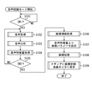
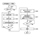
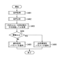
図2に、第1の実施形態の撮像装置100において実行される処理手順の一例を説明するフローチャートを示す。
図1の撮像装置において、音声認識モードスイッチ156により音声認識モードが選択されている場合に、以下のフローが処理実行される。
ステップS101では、135のレリーズスイッチが半押し(SW1)の状態であるかどうかを判別する。SW1がONであればステップS102へ移行する。
FIG. 2 is a flowchart illustrating an example of a processing procedure executed in the
In the imaging apparatus of FIG. 1, when the voice recognition mode is selected by the voice
In step S101, it is determined whether or not the
ステップS102では、マイクロフォン150より音声信号を取得する。
ステップS103では、音声分析処理部155により、入力された音声信号の音量レベル及び周波数を分析する。
In step S102, an audio signal is acquired from the
In step S103, the sound
ステップS104では、システム制御部120において、取得した音声信号の音量レベル及び周波数分布から所定の演算処理を施し、音声取得期間内の平均音量レベル、単位時間当たりの音量変化率、平均周波数、単位時間当たりの平均周波数の変化率を演算する。そして演算結果から、入力音声の音量やテンポ、音高、抑揚等の音声特徴量を抽出する。詳細は後述する。
In step S104, the
ステップS105では、135のレリーズスイッチが全押し(SW2)の状態であるかどうかを判別する。この判別の結果、レリーズスイッチが全押しSW2がONであれば音声取得を停止し、レリーズ動作を開始する。また、レリーズスイッチが全押しSW2がONでなければステップS102に戻る。つまり、レリーズスイッチ135が、SW1がONされてからSW2がONされるまでの間が、音声取得期間となる。
In step S105, it is determined whether or not the
ステップS106では、撮像素子121から読み出した信号を画像データに変換してメモリ127に書き込む撮像処理が行われる。
ステップS107では、ステップS104で得られた音声特徴量に対応するコントラスト・明度・彩度・シャープネス等の画像処理パラメータ値を設定する。
In step S <b> 106, an imaging process is performed in which a signal read from the
In step S107, image processing parameter values such as contrast, brightness, saturation, and sharpness corresponding to the audio feature value obtained in step S104 are set.
ステップS108では、所定の画素補間処理や色変換処理に加え、ステップS107で設定したパラメータに基づく画像処理を施し、画像データの圧縮処理を行う。
ステップS109では、ステップS108において得られた画像データを外部着脱メモリ部131に記録する。また、表示装置110に画像を表示する。
In step S108, in addition to predetermined pixel interpolation processing and color conversion processing, image processing based on the parameters set in step S107 is performed, and image data compression processing is performed.
In step S109, the image data obtained in step S108 is recorded in the external
次に、音声特徴量の抽出方法について説明する。
前述の通り、音声信号は音声分析処理部155により分析される。音声分析処理部155はスペクトルアナライザ機能を含み、取得した音声信号の周波数分布を得ることができる。これにより、図3に示すように各周波数域における音量レベルを取得することができる。
Next, a method for extracting voice feature amounts will be described.
As described above, the voice signal is analyzed by the voice
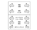
前述のようにして得られた周波数分布から、下記の式1、式2、式3、式4より音声取得時間内の平均音量A、単位時間当たりの音量変化率B、平均周波数C、単位時間当たりの平均周波数の変化率Dを求めることができる。ただし、Tは音声取得サンプリング回数の総数、Kは周波数のサンプリング数、ft、kは音声取得サンプリングt回目でのサンプリングk番目の周波数。at、kは周波数ft、kでの音量レベルを表す。
From the frequency distribution obtained as described above, the average volume A within the voice acquisition time, the volume change rate B per unit time, the average frequency C, and the unit time from the following

ここで、前記の単位時間当たりの音量変化率Bは入力音声信号のテンポ、平均周波数Cは音高、単位時間当たりの平均周波数の変化率Dは抑揚に対応する。以上より、入力音声の特徴量である音量・テンポ・音高・抑揚を取得することができる。なお、前述した4式は、簡略のために移動平均式としても構わない。 Here, the volume change rate B per unit time corresponds to the tempo of the input audio signal, the average frequency C corresponds to the pitch, and the change rate D of the average frequency per unit time corresponds to the inflection. As described above, the volume, tempo, pitch, and intonation, which are the feature quantities of the input voice, can be acquired. Note that the above-described four formulas may be moving average formulas for simplicity.
次に、画像処理パラメータの設定方法について説明する。変更する画像処理パラメータはコントラスト、シャープネス、明度、彩度、ホワイトバランスとする。デフォルト時の画像処理に対して、入力音声の特徴量である音量・テンポ・音高・抑揚の強弱に応じて、各効果の強弱を調整する。 Next, a method for setting image processing parameters will be described. The image processing parameters to be changed are contrast, sharpness, brightness, saturation, and white balance. For the default image processing, the strength of each effect is adjusted according to the strength, volume, tempo, pitch, and inflection, which are the features of the input sound.
以下、コントラストを例に設定方法を示す。コントラストはコントラスト設定値Crに比例して効果の強弱が変わる画像処理テーブルを有している。コントラスト設定値Crの値が大きいほどコントラストが強くなり、小さいほどコントラストが弱くなる。 Hereinafter, the setting method will be described by taking contrast as an example. The contrast has an image processing table in which the strength of the effect changes in proportion to the contrast setting value Cr. The greater the contrast setting value Cr, the stronger the contrast, and the smaller the contrast setting value Cr, the weaker the contrast.
音声特徴量は各々のコントラスト調整用パラメータとして、音量Vcr・テンポTcr・音高Pcr・抑揚Icrをもち、取得した特徴量の強弱に応じて各々の値が設定される。前記パラメータを用いて、コントラスト設定値Crは式5より求まる。
Cr = Cro×Vcr×Tcr×Pcr×Icr (式5)
ここで、Croはコントラストのデフォルト設定値である。
The audio feature amount includes volume Vcr, tempo Tcr, pitch Pcr, and inflection Icr as parameters for contrast adjustment, and each value is set according to the strength of the acquired feature amount. Using the parameters, the contrast setting value Cr is obtained from
Cr = Cro × Vcr × Tcr × Pcr × Icr (Formula 5)
Here, Cro is a default setting value of contrast.
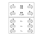
ここで、各画像処理パラメータと音声特徴量とは図4の関係にあるものとする。コントラスト設定値を例とすれば、音量・抑揚が大きいほどコントラストは強まり、音高・テンポが大きいほどコントラストは弱まるものとする。つまり、前記の式5において各音声特徴量がデフォルトより大きければ、音量Vcr・抑揚Icrは1より大きな値となり、音高Pcr・テンポTcrは1より小さな値となる。
Here, it is assumed that each image processing parameter and the audio feature amount have the relationship shown in FIG. Taking the contrast setting value as an example, it is assumed that the contrast increases as the volume / inflection increases, and the contrast decreases as the pitch / tempo increases. That is, if each voice feature amount is larger than the default in
以上、コントラストを例に設定方法を示したが、シャープネス、明度、彩度、ホワイトバランスについても同様の画像処理テーブルをもち、音声特徴量の値に応じて、各々の効果が変わる。ただし、図4に示すように、音声特徴量に対する各々の効果の変化の方向は異なる。 The setting method has been described above by taking contrast as an example, but the same image processing table is used for sharpness, lightness, saturation, and white balance, and each effect varies depending on the value of the audio feature amount. However, as shown in FIG. 4, the direction of change of each effect on the audio feature amount is different.
例えば、音量及び抑揚が高い環境下では、画像の明度・彩度を強くして印象的な画像にする。また、コントラストとシャープネスを下げるとともにホワイトバランスを黄色側にシフトさせることで、柔らかく、明るい印象をもたせる絵作りを行う。 For example, in an environment where the volume and inflection are high, the brightness and saturation of the image are increased to make an impressive image. In addition, by reducing the contrast and sharpness and shifting the white balance to the yellow side, we create a picture that gives a soft and bright impression.
一方で、音量・抑揚が小さく、高音でテンポが速い環境下では、明度・彩度を下げ、かつホワイトバランスを青色側へシフトさせる。そして、コントラスト・シャープネスの効果を上げ、引き締まった画像に仕上げる。 On the other hand, in an environment where the volume / inflection is small, the sound is high, and the tempo is fast, the brightness / saturation is lowered and the white balance is shifted to the blue side. Then, the effect of contrast and sharpness is enhanced to produce a tight image.
以上、第1の実施形態の構成によれば、撮影直前の環境音を取得し、画像処理に反映させることが可能になる。なお、前述した第1の実施形態ではレリーズスイッチ135が半押し(SW1)から全押し(SW2)になるまでの期間を音声取得期間としたが、レリーズスイッチ135以外のボタンを使用してもよい。
As described above, according to the configuration of the first embodiment, it is possible to acquire the environmental sound immediately before shooting and reflect it in the image processing. In the first embodiment described above, the period from when the
また、音声取得期間が他の任意の期間であってもよい。例えば、撮影前に予め取得しておいた音声特徴量に基づいて、画像処理を施してもよい。また、撮影後に音声特徴量を抽出し、既に撮影された画像に画像処理を施してもよい。 The voice acquisition period may be any other period. For example, image processing may be performed based on a voice feature amount acquired in advance before shooting. In addition, a voice feature amount may be extracted after shooting, and image processing may be performed on an already shot image.
(第2の実施形態)
次に、本発明の第2の実施形態を説明する。
前述した第1の実施形態では、静止画撮影時において本発明を実行する例を説明したが、第2の実施形態では動画撮影時に本発明を適用する例を説明する。本実施形態の撮像装置の構成は、第1の実施形態と同様であるため、撮像装置の構成を説明する図面は省略する。
(Second Embodiment)
Next, a second embodiment of the present invention will be described.
In the first embodiment described above, an example in which the present invention is executed during still image shooting has been described. In the second embodiment, an example in which the present invention is applied during moving image shooting will be described. Since the configuration of the imaging apparatus of the present embodiment is the same as that of the first embodiment, drawings for describing the configuration of the imaging apparatus are omitted.
図5に、第2の実施形態において処理実行される処理手順を説明するフローチャートを示す。
図1の撮像装置100に配設されている音声認識モードスイッチ156により音声認識モードが選択されている場合に、以下のフローが処理実行される。
FIG. 5 shows a flowchart for explaining a processing procedure executed in the second embodiment.
When the voice recognition mode is selected by the voice
まず、ステップS201では、操作部136の動画スイッチ(図示せず)が押され、動画撮影が開始状態であるかどうかを判別する。この判別の結果、動画撮影が開始状態であればステップS202へ移行する。
ステップS202では、撮像素子121から読み出した信号を画像データに変換してメモリ127に書き込む撮像処理が行われる。また、マイクロフォン150より音声信号を取得する。次に、ステップS203では、ステップS202で取得した画像データを処理するか、音声信号を処理するかの選択が行われ、音声信号を処理する場合にはステップS204へ移行する。また、画像データを処理する場合にはステップS206へ移行する。
First, in step S201, a moving image switch (not shown) of the
In step S202, an imaging process is performed in which the signal read from the
ステップS204では、入力された音声信号の音量レベル及び周波数を音声分析処理部155により分析する。
次に、ステップS205では、ステップS204で取得した音声信号の音量レベル及び周波数分布から所定の演算処理をシステム制御部120において施す。これにより、音声取得期間内の平均音量レベル、単位時間当たりの音量変化率、平均周波数、単位時間当たりの平均周波数の変化率を演算する。そして、演算結果から、入力音声の音量やテンポ、音高、抑揚等の音声特徴量を抽出する。音声特徴量を抽出する詳細は第1の実施形態に示した通りである。
In step S204, the sound
Next, in step S205, the
ただし、動画撮影の場合には、取得した音声特徴量を画像処理に動的に反映する必要があるため、移動平均式を用いて単位時間当たりの音量変化率、平均周波数、単位時間当たりの平均周波数の変化率を演算することが望ましい。 However, in the case of video shooting, the acquired audio feature value needs to be dynamically reflected in the image processing, so the volume change rate per unit time, average frequency, average per unit time using the moving average formula It is desirable to calculate the rate of change of frequency.
次に、ステップS206では、ステップS205で得られた音声特徴量に対応するコントラスト・明度・彩度・シャープネス等の画像処理パラメータ値を設定する。
次に、ステップS207では、所定の画素補間処理や色変換処理に加え、S207で設定したパラメータに基づく画像処理を施す。
Next, in step S206, image processing parameter values such as contrast, brightness, saturation, and sharpness corresponding to the audio feature amount obtained in step S205 are set.
In step S207, in addition to predetermined pixel interpolation processing and color conversion processing, image processing based on the parameters set in S207 is performed.
次に、ステップS208では、操作部136の動画スイッチが押され、動画撮影が停止状態であるかどうかを判別する。この判断の結果、動画撮影が停止状態であればステップS209へ移行する。また、動画撮影が停止状態でなかった場合にはステップS202に戻り、前述した動作を実行する。
Next, in step S208, it is determined whether the moving image switch of the
ステップS209では、取得した動画データを画像処理部123にてMPEG方式によりデータ圧縮する。また、音声データはAudio Codec部152により圧縮処理される。
次に、ステップS210では、ステップS209で圧縮された動画像ファイル及び音声ファイルを動画ファイル(動画データ+音声データ)として外部着脱メモリ部131に記録する。
In step S209, the acquired moving image data is compressed by the
Next, in step S210, the moving image file and the audio file compressed in step S209 are recorded in the external
以上、説明した第2の実施形態において、音声特徴量の抽出方法及び画像処理パラメータの変更方法は前述した第1の実施形態と同様であるため、説明は省略する。第2の実施形態によれば、撮影している際の音声特徴量に基づいて画像処理を変更する本発明を、動画像に対しても適用することが可能となる。 As described above, in the second embodiment described above, the audio feature extraction method and the image processing parameter change method are the same as those in the first embodiment described above, and thus the description thereof is omitted. According to the second embodiment, it is possible to apply the present invention that changes the image processing based on the sound feature amount during shooting to a moving image.
(第3の実施形態)
前述した、第1の実施形態及び第2の実施形態では、音声特徴量に基づき画像処理パラメータを変更する例を説明した。それに対して、第3の実施形態では、音声特徴量に基づいて撮影パラメータを変更する例を説明する。なお、撮像装置の構成は図1で説明した第1の実施形態と同様であるため、撮像装置の構成を説明する図面は省略する。
(Third embodiment)
In the first embodiment and the second embodiment described above, the example in which the image processing parameter is changed based on the audio feature amount has been described. On the other hand, in the third embodiment, an example in which the shooting parameter is changed based on the audio feature amount will be described. Since the configuration of the imaging apparatus is the same as that of the first embodiment described with reference to FIG. 1, drawings for describing the configuration of the imaging apparatus are omitted.
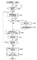
図6に、第3の実施形態において行われる撮像方法の処理手順を説明するフローチャートを示す。この処理は、図1の撮像装置において、音声認識モードスイッチ156により音声認識モードが選択されている場合に実行される。
FIG. 6 is a flowchart for explaining the processing procedure of the imaging method performed in the third embodiment. This process is executed when the voice recognition mode is selected by the voice
まず、ステップS301では、接眼検出部130において、接眼が検出されているかどうかを判別する。この判断の結果、接眼状態にあればステップS302へ移行する。
ステップS302では、マイクロフォン150より音声信号を取得する。その後、ステップS303に進む。ステップS303では、マイクロフォン150から入力された音声信号の音量レベル及び周波数を音声分析処理部155により分析する。
First, in step S301, the
In step S302, an audio signal is acquired from the
次に、ステップS304では、取得した音声信号の音量レベル及び周波数分布から所定の演算処理をシステム制御部120で施し、音声取得期間内の平均音量レベル、単位時間当たりの音量変化率、平均周波数、単位時間当たりの平均周波数の変化率を演算する。そして、演算結果から、入力音声の音量やテンポ、音高、抑揚等の音声特徴量を抽出する。詳細は第1の実施形態に示す。
Next, in step S304, the
次に、ステップS305では、レリーズスイッチ135が半押し(SW1)の状態であるかどうかを判別する。この判断の結果、SW1がONであれば音声取得を停止し、撮影モードへ移行する。つまり、接眼検出部130により接眼が検知されてからSW1がONされるまでの間が、音声取得期間となる。
ステップS306では、測光部142より得られた被写体及び被写体の周辺部の明るさを示す測光値より自動露出補正(AE)が行われ、絞り及びシャッタースピードが設定される。
Next, in step S305, it is determined whether or not the
In step S306, automatic exposure correction (AE) is performed based on the photometric value indicating the brightness of the subject and the peripheral portion of the subject obtained from the
ステップS307では、ステップS306で得られた絞り及びシャッタースピードの設定値を、ステップS304で得られた音声特徴量に基づいて変更する。
ステップS308では、レリーズスイッチ135が全押し(SW2)の状態であるかどうかを判別する。
In step S307, the aperture and shutter speed set values obtained in step S306 are changed based on the audio feature values obtained in step S304.
In step S308, it is determined whether or not the
ステップS308の判断の結果、SW2がONであればステップS309へ移行する。ステップS309では、ステップS307で設定された絞り及びシャッタースピードの設定値に基づいて撮影動作が行われる。なお、第3の実施形態において、音声特徴量の抽出方法は第1の実施形態と同様であるため、詳細な説明は省略する。 As a result of the determination in step S308, if SW2 is ON, the process proceeds to step S309. In step S309, a shooting operation is performed based on the aperture and shutter speed setting values set in step S307. Note that in the third embodiment, the method for extracting voice feature amounts is the same as that in the first embodiment, and thus detailed description thereof is omitted.
次に、撮影パラメータの設定方法について説明する。変更する撮影パラメータは絞り、シャッタースピードの設定値とする。
図6のステップ306で得られたデフォルトの絞り及びシャッタースピードに対して、入力音声の特徴量である音量・テンポ・音高・抑揚の強弱に応じて、設定値を調整する。
Next, a method for setting shooting parameters will be described. The shooting parameters to be changed are the aperture and shutter speed settings.
With respect to the default aperture and shutter speed obtained in
露出(Ev)、絞り(Av)、シャッタースピード(Tv)に対して、音声特徴パラメータとして、音量V*・テンポT*・音高P*・抑揚I*(*=evは露出、*=avは絞り、*=tvはシャッタースピードのパラメータである)をそれぞれ有する。本実施形態においては、ステップS304で取得した特徴量の強弱に応じて各々の値が設定される。 As an audio feature parameter for exposure (Ev), aperture (Av), and shutter speed (Tv), volume V *, tempo T *, pitch P *, inflection I * (* = ev is exposure, * = av Is an aperture, and * = tv is a shutter speed parameter. In this embodiment, each value is set according to the strength of the feature amount acquired in step S304.
すなわち、以下の式6より露出補正パラメータKevが求まる。Kevは露出を何段明るくすべきかを決定するパラメータである。また、デフォルトの露出値をEvoとすれば、補正後の露出EvはEvoをKev段だけ明るくした値となる。 That is, the exposure correction parameter Kev is obtained from the following equation (6). Kev is a parameter that determines how much exposure should be increased. If the default exposure value is Evo, the corrected exposure Ev is a value obtained by increasing Evo by Kev level.
同様に、絞りAv、シャッタースピードTvについても、以下の式7より絞り補正パラメータKav、以下の式8よりシャッタースピード補正パラメータKtvが求まる。補正後の絞りAvはデフォルトの設定値Avoに対してKav段下げた値となり、補正後のシャッタースピードTvはデフォルトの設定値Tvoに対してKtv段上げた値となる。 Similarly, with respect to the aperture Av and the shutter speed Tv, the aperture correction parameter Kav is obtained from the following equation 7, and the shutter speed correction parameter Ktv is obtained from the following equation 8. The corrected aperture Av is a value lowered by a Kav step relative to the default set value Avo, and the corrected shutter speed Tv is a value raised by a Ktv step relative to the default set value Tvo.
ここで、各音声特徴量と撮影パラメータの関係は、図7の関係にあるものとする。例えば、音量及び抑揚が高い環境下では、絞りを開放側に補正し、かつシャッタースピードを下げ、露出を高くすることで、柔らかく、明るい印象をもつ画像を撮影できる。一方で、音量・抑揚が小さく、高音でテンポが速い環境下では、露出を下げ、絞り込み、かつシャッタースピードを上げ、引き締まった画像に仕上げるようにする。 Here, it is assumed that the relationship between each audio feature amount and the shooting parameter is as shown in FIG. For example, in an environment where the volume and the inflection are high, an image having a soft and bright impression can be taken by correcting the aperture to the open side, decreasing the shutter speed, and increasing the exposure. On the other hand, in an environment where the volume / inflection is low, the sound is high, and the tempo is fast, the exposure is reduced, the aperture is narrowed down, and the shutter speed is increased to produce a tight image.
以上説明した第3の実施形態によれば、画像処理機能に乏しい撮像装置に対しても、本発明を適用することが可能となる。また、第1の実施形態と組み合わせることで、相乗効果が期待できる。 According to the third embodiment described above, the present invention can be applied to an imaging apparatus having a poor image processing function. Further, a synergistic effect can be expected by combining with the first embodiment.
また、第3の実施形態では、静止画撮影を想定しているが、動画撮影時に適用してもよい。例えば、動画の場合は露出及び絞りの制御に加えて、シャッタースピード調整の代わりに、撮影時のフレームレートを変更してもよい。例えば、音声特徴量の内、テンポが速ければ動画のフレームレートを間引くことで、再生時に早送りの効果となり、臨場感がより伝わる。 In the third embodiment, still image shooting is assumed, but it may be applied during moving image shooting. For example, in the case of a moving image, in addition to exposure and aperture control, the frame rate at the time of shooting may be changed instead of adjusting the shutter speed. For example, if the tempo is fast among the audio feature amounts, the frame rate of the moving image is thinned out, resulting in a fast-forward effect during reproduction, and a sense of realism is transmitted more.
また、第3の実施形態では接眼検出部130において接眼が検出されてから、レリーズスイッチ135が半押し(SW1)されるまでの期間を音声取得期間としたが、他のボタンを使用してもよい。また、音声取得期間が他の任意の期間であってもよい。例えば、撮影前に予め取得しておいた音声特徴量に基づいて、撮影パラメータを設定してもよい。
In the third embodiment, the period from when the eyepiece is detected by the
(第4の実施形態)
次に、本発明の第4の実施形態を説明する。
前述した第1の実施形態〜第3の実施形態では、音声信号の特徴量を音量・テンポ・音高・抑揚として画像処理パラメータ及び撮影パラメータを変更していた。それに対して、第4の実施形態では、取得した周波数成分の分布が可聴域範囲内であるかを判定し、判定結果に応じて設定する画像処理パラメータ及び撮影パラメータを変更する。
(Fourth embodiment)
Next, a fourth embodiment of the present invention will be described.
In the first to third embodiments described above, the image processing parameters and the shooting parameters are changed with the feature amount of the audio signal as the volume, tempo, pitch, and inflection. On the other hand, in the fourth embodiment, it is determined whether the distribution of the acquired frequency component is within the audible range, and the image processing parameter and the imaging parameter set according to the determination result are changed.
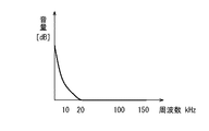
一般的に、都市部は人間の可聴域(20kHz)を越える音はほとんど存在しない。図8は、都市市街地の環境音の周波数分布を概略図として示したものであるが、平均周波数上限は、約10kHz程度にとどまっている。 In general, there is almost no sound exceeding the human audible range (20 kHz) in urban areas. FIG. 8 is a schematic diagram showing the frequency distribution of environmental sounds in an urban city area, but the upper limit of the average frequency is only about 10 kHz.
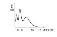
一方で、図9は熱帯雨林等の自然環境における環境音の周波数分布の概略図であるが、150kHz以上に達する音として聴こえない高周波成分が溢れている。そこで、第1の実施形態〜第3の実施形態に示す構成の撮像装置において、撮影時に取得した環境音の内、可聴域(20kHz)を越える周波数成分の平均音量レベルを算出する。そして、撮影環境が自然環境であるか都市環境であるかどうかを判別し、自然環境若しくは都市環境用の画像処理及び撮影パラメータを設定する。 On the other hand, FIG. 9 is a schematic diagram of the frequency distribution of the environmental sound in a natural environment such as a rainforest, but is filled with high frequency components that cannot be heard as sound reaching 150 kHz or higher. Therefore, in the imaging apparatus having the configuration shown in the first to third embodiments, the average volume level of frequency components exceeding the audible range (20 kHz) is calculated from the environmental sound acquired at the time of shooting. Then, it is determined whether the shooting environment is a natural environment or an urban environment, and image processing and shooting parameters for the natural environment or the urban environment are set.
図10に、第4の実施形態の処理手順を説明するフローチャートを示す。その他の構成は第1の実施形態〜第3の実施形態と同様のため、撮像装置の構成を説明するブロック図及び説明は省略する。
まず、ステップS401では、マイクロフォン150により音声信号を取得する。
ステップS402では、音声分析処理部155により、マイクロフォン150から出力された音声信号の音量レベル及び周波数を分析する。
FIG. 10 is a flowchart for explaining the processing procedure of the fourth embodiment. Since other configurations are the same as those in the first to third embodiments, a block diagram and a description for describing the configuration of the imaging apparatus are omitted.
First, in step S401, an audio signal is acquired by the
In step S402, the sound
次に、ステップS403では、取得した音声信号の音量レベル及び周波数分布から所定の演算処理をシステム制御部120で施し、可聴域(20kHz)を越える周波数成分の平均音量レベルを算出する。
Next, in step S403, predetermined calculation processing is performed by the
次に、ステップS404では、可聴域(20kHz)を越える周波数成分の平均音量レベルが、予め定めた閾値以上かどうかを判別する。この判別の結果、閾値以上であればステップS406へ移行し、閾値未満であればステップS405へ移行する。 Next, in step S404, it is determined whether or not the average volume level of frequency components exceeding the audible range (20 kHz) is equal to or higher than a predetermined threshold value. If it is determined that the threshold value is equal to or greater than the threshold value, the process proceeds to step S406, and if it is less than the threshold value, the process proceeds to step S405.
ステップS405では、撮影環境は都市部と判定し、都市部用のパラメータを設定する。例えば、明度・彩度を下げ、かつホワイトバランスを青色側へシフトさせる。そして、コントラスト・シャープネスの効果を上げ、引き締まった画像に仕上げることで、人工物に囲まれた雰囲気を出すようにする。 In step S405, the shooting environment is determined to be an urban area, and parameters for the urban area are set. For example, the brightness / saturation is lowered and the white balance is shifted to the blue side. Then, the effect of contrast and sharpness is enhanced and the image is tightened to create an atmosphere surrounded by artifacts.
一方、ステップS406では、撮影環境は自然環境と判定し、自然環境用のパラメータを設定する。例えば、画像の明度・彩度を強くし、色鮮やかな画像にする。また、コントラストとシャープネスを下げることで、柔らかく、明るい印象をもたせる画像作りを行う。 On the other hand, in step S406, it is determined that the shooting environment is a natural environment, and parameters for the natural environment are set. For example, the brightness / saturation of the image is increased to make the image colorful. Also, by reducing the contrast and sharpness, the image is created to give a soft and bright impression.
以上、第4の実施形態の構成を説明した。なお、第4の実施形態では画像処理パラメータのみ変更しているが、撮影パラメータを変更してもよい。また、音量・音高・テンポ・抑揚等の他の音声特徴量を併用してもよい。 The configuration of the fourth embodiment has been described above. In the fourth embodiment, only the image processing parameters are changed, but the shooting parameters may be changed. Moreover, you may use together other audio | voice feature-values, such as volume, pitch, tempo, and inflection.
また、前述した実施形態では、環境音を可聴域内と可聴域外の2つに分類して画像処理パラメータを変更しているが、分類をより細かくしてもよい。例えば10kHz、20kHz、50kHz、100kHzにおいて各々音量を判別し、撮影環境を類推して画像処理パラメータ及び撮影パラメータを変更してもよい。 Further, in the above-described embodiment, the environmental sound is classified into two within the audible range and outside the audible range, and the image processing parameter is changed. However, the classification may be made finer. For example, the volume may be determined at 10 kHz, 20 kHz, 50 kHz, and 100 kHz, and the image processing parameter and the shooting parameter may be changed by analogy with the shooting environment.
以上、4つの実施形態について説明した。
なお、実施形態の説明においては、撮像装置100は、レンズ交換可能なデジタルカメラを想定した構成となっているが、レンズ一体型のコンパクトデジタルカメラやカメラ付携帯電話、及びデジタルビデオカメラのような構成としてもよい。
The four embodiments have been described above.
In the description of the embodiment, the
また、4つの実施形態を別々に説明したが、各々が組み合わされた構成としてもよい。また、静止画撮影時と動画撮影時について別々に説明しているが、動画撮影時に撮影する静止画に本発明を適用してもよい。 Moreover, although four embodiment was demonstrated separately, it is good also as a structure by which each was combined. Further, although the still image shooting and the moving image shooting are separately described, the present invention may be applied to a still image shot during moving image shooting.
また、前述した実施形態の中では、音声特徴量に対する画像処理パラメータ及び撮影パラメータの設定例を図4及び図7のように示したが、音声特徴量と各パラメータの関係は、本実施形態と異なる設定でもよい。 In the above-described embodiment, the setting examples of the image processing parameter and the shooting parameter for the audio feature amount are shown as in FIGS. 4 and 7, but the relationship between the audio feature amount and each parameter is the same as that of the present embodiment. Different settings may be used.
また、実施形態の中で画像特徴量に基づき変更するパラメータは、コントラスト、明度、彩度、シャープネス、ホワイトバランスとしたが、他の画像処理パラメータを変更するようにしてもよい。 In the embodiment, the parameters to be changed based on the image feature amount are contrast, brightness, saturation, sharpness, and white balance. However, other image processing parameters may be changed.
また、前述においては、音声特徴量に基づき画像処理を施した画像データのみ記録媒体に保存しているが、画像処理を施す前のCCDRAWデータや、デフォルトの画像処理を施した画像データを同時に保存できるように構成してもよい。 In the above description, only image data that has undergone image processing based on audio feature values is stored in the recording medium. However, CCD RAW data before image processing and image data that has undergone default image processing are simultaneously stored. You may comprise so that it can do.
また、撮像装置100に外部着脱メモリ部131を装着する構成として説明したが、記録媒体は単数或いは複数の何れを組み合わせた構成であってもよい。また、前述した実施形態ではカメラ制御部140、システム制御部120は、独立した回路構成としているが、システム制御部120がカメラ制御部140を兼ね備えた構成であってもよい。
Further, although the configuration has been described in which the external
また、実施形態の説明においては、撮像装置100は、不揮発性メモリにプログラムや、表示データを備えた構成を想定しているが、ハードディスクやDVD−ROM、CD−ROM等による構成としてもよい。
In the description of the embodiment, the
(本発明に係る他の実施形態)
前述した本発明の実施形態における撮像装置を構成する各手段は、コンピュータのRAMやROMなどに記憶されたプログラムが動作することによって実現できる。このプログラム及び前記プログラムを記録したコンピュータ読み取り可能な記録媒体は本発明に含まれる。
(Other embodiments according to the present invention)
Each unit constituting the imaging apparatus according to the above-described embodiment of the present invention can be realized by operating a program stored in a RAM or a ROM of a computer. This program and a computer-readable recording medium recording the program are included in the present invention.
また、本発明は、例えば、システム、装置、方法、プログラムもしくは記憶媒体等としての実施形態も可能であり、具体的には、複数の機器から構成されるシステムに適用してもよいし、また、一つの機器からなる装置に適用してもよい。 In addition, the present invention can be implemented as, for example, a system, apparatus, method, program, storage medium, or the like. Specifically, the present invention may be applied to a system including a plurality of devices. The present invention may be applied to an apparatus composed of a single device.
なお、本発明は、前述した撮像方法における各工程を実行するソフトウェアのプログラム(実施形態では図2、図5、図6及び図10に示すフローチャートに対応したプログラム)を、システムあるいは装置に直接、あるいは遠隔から供給する。そして、そのシステムあるいは装置のコンピュータが前記供給されたプログラムコードを読み出して実行することによっても達成される場合を含む。 In the present invention, a software program (in the embodiment, a program corresponding to the flowcharts shown in FIGS. 2, 5, 6, and 10) that executes each step in the imaging method described above is directly transferred to a system or apparatus. Alternatively, it is supplied remotely. In addition, this includes a case where the system or the computer of the apparatus is also achieved by reading and executing the supplied program code.
したがって、本発明の機能処理をコンピュータで実現するために、前記コンピュータにインストールされるプログラムコード自体も本発明を実現するものである。つまり、本発明は、本発明の機能処理を実現するためのコンピュータプログラム自体も含まれる。 Accordingly, since the functions of the present invention are implemented by computer, the program code installed in the computer also implements the present invention. In other words, the present invention includes a computer program itself for realizing the functional processing of the present invention.
その場合、プログラムの機能を有していれば、オブジェクトコード、インタプリタにより実行されるプログラム、OSに供給するスクリプトデータ等の形態であってもよい。 In that case, as long as it has the function of a program, it may be in the form of object code, a program executed by an interpreter, script data supplied to the OS, and the like.
プログラムを供給するための記録媒体としては種々の記録媒体を使用することができる。例えば、フロッピー(登録商標)ディスク、ハードディスク、光ディスク、光磁気ディスク、MO、CD−ROM、CD−R、CD−RW、磁気テープ、不揮発性のメモリカード、ROM、DVD(DVD−ROM,DVD−R)などがある。 Various recording media can be used as a recording medium for supplying the program. For example, floppy (registered trademark) disk, hard disk, optical disk, magneto-optical disk, MO, CD-ROM, CD-R, CD-RW, magnetic tape, nonvolatile memory card, ROM, DVD (DVD-ROM, DVD- R).
その他、プログラムの供給方法としては、クライアントコンピュータのブラウザを用いてインターネットのホームページに接続する。そして、前記ホームページから本発明のコンピュータプログラムそのもの、もしくは圧縮され自動インストール機能を含むファイルをハードディスク等の記録媒体にダウンロードすることによっても供給できる。 As another program supply method, a browser on a client computer is used to connect to an Internet home page. The computer program itself of the present invention or a compressed file including an automatic installation function can be downloaded from the homepage by downloading it to a recording medium such as a hard disk.
また、本発明のプログラムを構成するプログラムコードを複数のファイルに分割し、それぞれのファイルを異なるホームページからダウンロードすることによっても実現可能である。つまり、本発明の機能処理をコンピュータで実現するためのプログラムファイルを複数のユーザに対してダウンロードさせるWWWサーバも、本発明に含まれるものである。 It can also be realized by dividing the program code constituting the program of the present invention into a plurality of files and downloading each file from a different homepage. That is, a WWW server that allows a plurality of users to download a program file for realizing the functional processing of the present invention on a computer is also included in the present invention.
また、本発明のプログラムを暗号化してCD−ROM等の記憶媒体に格納してユーザに配布し、所定の条件をクリアしたユーザに対し、インターネットを介してホームページから暗号化を解く鍵情報をダウンロードさせる。そして、その鍵情報を使用することにより暗号化されたプログラムを実行してコンピュータにインストールさせて実現することも可能である。 In addition, the program of the present invention is encrypted, stored in a storage medium such as a CD-ROM, distributed to users, and key information for decryption is downloaded from a homepage via the Internet to users who have cleared predetermined conditions. Let It is also possible to execute the encrypted program by using the key information and install the program on a computer.
また、コンピュータが、読み出したプログラムを実行することによって、前述した実施形態の機能が実現される他、コンピュータ上で稼動しているOSなどが、実際の処理の一部または全部を行うことによっても前述した実施形態の機能が実現され得る。 In addition to the functions of the above-described embodiments being realized by the computer executing the read program, the OS running on the computer may perform part or all of the actual processing. The functions of the above-described embodiments can be realized.
さらに、記録媒体から読み出されたプログラムが、コンピュータに挿入された機能拡張ボードやコンピュータに接続された機能拡張ユニットに備わるメモリに書き込まれる。その後、そのプログラムの指示に基づき、その機能拡張ボードや機能拡張ユニットに備わるCPUなどが実際の処理の一部または全部を行い、その処理によっても前述した実施形態の機能が実現される。 Further, the program read from the recording medium is written in a memory provided in a function expansion board inserted into the computer or a function expansion unit connected to the computer. Thereafter, the CPU of the function expansion board or function expansion unit performs part or all of the actual processing based on the instructions of the program, and the functions of the above-described embodiments are realized by the processing.
100 撮像装置
101 レンズ用コネクタ
102 レンズマウント(カメラ側)
110 表示装置
111 アクセサリシュー
120 システム制御部
121 撮像素子
122 A/D変換部
123 画像処理部
124 メモリ制御部
125 液晶パネル表示部
126 バックライト照明
127 メモリ
128 不揮発性メモリ
130 接眼検出部
131 外部着脱メモリ部
132 再生スイッチ
133 メニュースイッチ
134 モードダイアル
135 レリーズスイッチ
136 操作部
137 電源スイッチ
138 電源部
139 タイマー
140 カメラ制御部
141 シャッター制御部
142 測光部
143 測距部
144 シャッター
150 マイクロフォン
151 A/D変換部
152 Audio Codec部152
153 D/A変換部
154 スピーカ
155 音声分析処理部
156 音声認識モードスイッチ
200 レンズユニット
201 レンズ用コネクタ
202 レンズマウント(レンズ側)
203 レンズ制御部
210 撮影レンズ
211 絞り
300 ストロボユニット
301 インターフェース
302 ストロボ発光制御部
100
DESCRIPTION OF SYMBOLS 110
153 D /
203
Claims (9)
前記撮像手段によって生成された静止画像データまたは動画像データに所定の画像処理を施す画像処理手段と、
前記撮像手段が前記被写体を撮影する時に音声信号を取得する音声入力手段と、
前記音声入力手段によって取得された音声信号の特徴量を分析する音声分析処理手段と、
前記画像処理手段が前記静止画像データまたは動画像データに所定の画像処理を施すために用いる画像処理パラメータを、前記音声分析処理手段によって分析された音声信号の特徴量に基づいて制御するシステム制御手段とを有することを特徴とする撮像装置。 Imaging means for capturing a subject and generating still image data or moving image data;
Image processing means for performing predetermined image processing on still image data or moving image data generated by the imaging means;
Audio input means for acquiring an audio signal when the imaging means images the subject;
Voice analysis processing means for analyzing a feature amount of the voice signal acquired by the voice input means;
System control means for controlling image processing parameters used by the image processing means for performing predetermined image processing on the still image data or moving image data based on the feature amount of the audio signal analyzed by the audio analysis processing means. An imaging apparatus comprising:
前記システム制御手段は、前記音声分析処理手段の判定結果に応じて、前記画像処理手段が画像処理を行う際に設定する画像処理パラメータ、及び前記撮像手段が撮影する際の撮影パラメータを制御することを特徴とする請求項1〜6の何れか1項に記載の撮像装置。 The sound analysis processing means determines whether the distribution of frequency components acquired when the subject is photographed is within an audible range,
The system control unit controls an image processing parameter set when the image processing unit performs image processing and a shooting parameter when the imaging unit captures an image according to a determination result of the voice analysis processing unit. The imaging apparatus according to claim 1, wherein
前記撮像工程において生成された静止画像データまたは動画像データに所定の画像処理を施す画像処理工程と、
前記撮像工程において前記被写体を撮影する時に音声信号を取得する音声入力工程と、
前記音声入力工程において取得された音声信号の特徴量を分析する音声分析処理工程と、
前記画像処理工程において前記静止画像データまたは動画像データに所定の画像処理を施すために用いる画像処理パラメータを、前記音声分析処理工程において分析された音声信号の特徴量に基づいて制御するシステム制御工程とを有することを特徴とする撮像方法。 An imaging step of shooting a subject to generate still image data or moving image data;
An image processing step of performing predetermined image processing on still image data or moving image data generated in the imaging step;
An audio input step of acquiring an audio signal when shooting the subject in the imaging step;
A voice analysis processing step of analyzing a feature amount of the voice signal acquired in the voice input step;
A system control step for controlling image processing parameters used for performing predetermined image processing on the still image data or moving image data in the image processing step based on a feature amount of the audio signal analyzed in the audio analysis processing step. An imaging method characterized by comprising:
前記撮像工程において生成された静止画像データまたは動画像データに所定の画像処理を施す画像処理工程と、
前記撮像工程において前記被写体を撮影する時に音声信号を取得する音声入力工程と、
前記音声入力工程において取得された音声信号の特徴量を分析する音声分析処理工程と、
前記画像処理工程において前記静止画像データまたは動画像データに所定の画像処理を施すために用いる画像処理パラメータを、前記音声分析処理工程において分析された音声信号の特徴量に基づいて制御するシステム制御工程とを有する撮像方法をコンピュータに実行させることを特徴とするコンピュータプログラム。 An imaging step of shooting a subject to generate still image data or moving image data;
An image processing step of performing predetermined image processing on still image data or moving image data generated in the imaging step;
An audio input step of acquiring an audio signal when shooting the subject in the imaging step;
A voice analysis processing step of analyzing a feature amount of the voice signal acquired in the voice input step;
A system control step for controlling image processing parameters used for performing predetermined image processing on the still image data or moving image data in the image processing step based on a feature amount of the audio signal analyzed in the audio analysis processing step. A computer program that causes a computer to execute an imaging method including:
Priority Applications (1)
| Application Number | Priority Date | Filing Date | Title |
|---|---|---|---|
| JP2008319969A JP5235644B2 (en) | 2008-12-16 | 2008-12-16 | IMAGING DEVICE, IMAGE PROCESSING METHOD, AND IMAGING DEVICE CONTROL METHOD |
Applications Claiming Priority (1)
| Application Number | Priority Date | Filing Date | Title |
|---|---|---|---|
| JP2008319969A JP5235644B2 (en) | 2008-12-16 | 2008-12-16 | IMAGING DEVICE, IMAGE PROCESSING METHOD, AND IMAGING DEVICE CONTROL METHOD |
Publications (3)
| Publication Number | Publication Date |
|---|---|
| JP2010147587A true JP2010147587A (en) | 2010-07-01 |
| JP2010147587A5 JP2010147587A5 (en) | 2012-02-02 |
| JP5235644B2 JP5235644B2 (en) | 2013-07-10 |
Family
ID=42567590
Family Applications (1)
| Application Number | Title | Priority Date | Filing Date |
|---|---|---|---|
| JP2008319969A Active JP5235644B2 (en) | 2008-12-16 | 2008-12-16 | IMAGING DEVICE, IMAGE PROCESSING METHOD, AND IMAGING DEVICE CONTROL METHOD |
Country Status (1)
| Country | Link |
|---|---|
| JP (1) | JP5235644B2 (en) |
Cited By (2)
| Publication number | Priority date | Publication date | Assignee | Title |
|---|---|---|---|---|
| US9172858B2 (en) | 2011-11-21 | 2015-10-27 | Sony Corporation | Apparatus and method for controlling settings of an imaging operation |
| JP2022505118A (en) * | 2018-10-19 | 2022-01-14 | 北京微播視界科技有限公司 | Image processing method, equipment, hardware equipment |
Citations (3)
| Publication number | Priority date | Publication date | Assignee | Title |
|---|---|---|---|---|
| JP2005318084A (en) * | 2004-04-27 | 2005-11-10 | Fuji Photo Film Co Ltd | Photographing device |
| JP2008099110A (en) * | 2006-10-13 | 2008-04-24 | Olympus Corp | Imaging apparatus |
| JP2008182712A (en) * | 2007-01-25 | 2008-08-07 | Hewlett-Packard Development Co Lp | Applying visual effect to image data based on audio data |
-
2008
- 2008-12-16 JP JP2008319969A patent/JP5235644B2/en active Active
Patent Citations (3)
| Publication number | Priority date | Publication date | Assignee | Title |
|---|---|---|---|---|
| JP2005318084A (en) * | 2004-04-27 | 2005-11-10 | Fuji Photo Film Co Ltd | Photographing device |
| JP2008099110A (en) * | 2006-10-13 | 2008-04-24 | Olympus Corp | Imaging apparatus |
| JP2008182712A (en) * | 2007-01-25 | 2008-08-07 | Hewlett-Packard Development Co Lp | Applying visual effect to image data based on audio data |
Cited By (3)
| Publication number | Priority date | Publication date | Assignee | Title |
|---|---|---|---|---|
| US9172858B2 (en) | 2011-11-21 | 2015-10-27 | Sony Corporation | Apparatus and method for controlling settings of an imaging operation |
| JP2022505118A (en) * | 2018-10-19 | 2022-01-14 | 北京微播視界科技有限公司 | Image processing method, equipment, hardware equipment |
| JP7199527B2 (en) | 2018-10-19 | 2023-01-05 | 北京微播視界科技有限公司 | Image processing method, device, hardware device |
Also Published As
| Publication number | Publication date |
|---|---|
| JP5235644B2 (en) | 2013-07-10 |
Similar Documents
| Publication | Publication Date | Title |
|---|---|---|
| KR101786049B1 (en) | A digital photographing apparatus, a method for controlling the same, and a computer-readable storage medium for performing the method | |
| US20090027539A1 (en) | Imaging device, display control method, and program | |
| JP5076695B2 (en) | Image correction apparatus, image correction method, and program | |
| KR20100095232A (en) | Method for controlling white balance of an image, medium of recording the method and apparatus applying the method | |
| JP2006304001A (en) | Imaging apparatus | |
| US20060044460A1 (en) | Method of controlling digital photographing apparatus, and digital photographing apparatus utilizing the method | |
| JP2009177328A (en) | Imaging device | |
| KR20130024022A (en) | Digital photographing apparatus and control method thereof | |
| US10205872B2 (en) | Display control apparatus and method for controlling the same | |
| KR20170051274A (en) | Video processing apparatus, video processing method, program, and medium | |
| JP5494744B2 (en) | Imaging apparatus, control method, and program | |
| JP5491163B2 (en) | Display device and imaging device using the same | |
| JP2010063036A (en) | Imaging apparatus and image display method | |
| JP2008252595A (en) | Imaging apparatus and computer program therefor | |
| US7456893B2 (en) | Method of controlling digital image processing apparatus for efficient reproduction and digital image processing apparatus using the method | |
| JP5235644B2 (en) | IMAGING DEVICE, IMAGE PROCESSING METHOD, AND IMAGING DEVICE CONTROL METHOD | |
| KR20090076394A (en) | Digital photographing apparatus and method for controlling the same | |
| US20060044453A1 (en) | Method of controlling digital photographing apparatus, and digital photographing apparatus adopting the method | |
| KR101464532B1 (en) | Digital image processing apparatus and method for controlling the same | |
| JP2012100214A (en) | Imaging apparatus, correction program, and recording medium | |
| JP2006101558A (en) | Program photographing method and electronic image pickup apparatus | |
| KR101946574B1 (en) | Apparatus and method for reproducing image and computer-readable storage medium | |
| JP5872850B2 (en) | Imaging main body, imaging device system, and program | |
| US20060152613A1 (en) | Method and apparatus for displaying digital images | |
| JP2011166301A (en) | Imaging apparatus |
Legal Events
| Date | Code | Title | Description |
|---|---|---|---|
| A521 | Request for written amendment filed |
Free format text: JAPANESE INTERMEDIATE CODE: A523 Effective date: 20111212 |
|
| A621 | Written request for application examination |
Free format text: JAPANESE INTERMEDIATE CODE: A621 Effective date: 20111212 |
|
| A977 | Report on retrieval |
Free format text: JAPANESE INTERMEDIATE CODE: A971007 Effective date: 20120924 |
|
| A131 | Notification of reasons for refusal |
Free format text: JAPANESE INTERMEDIATE CODE: A131 Effective date: 20121009 |
|
| A521 | Request for written amendment filed |
Free format text: JAPANESE INTERMEDIATE CODE: A523 Effective date: 20121210 |
|
| A131 | Notification of reasons for refusal |
Free format text: JAPANESE INTERMEDIATE CODE: A131 Effective date: 20130108 |
|
| A521 | Request for written amendment filed |
Free format text: JAPANESE INTERMEDIATE CODE: A523 Effective date: 20130205 |
|
| TRDD | Decision of grant or rejection written | ||
| A01 | Written decision to grant a patent or to grant a registration (utility model) |
Free format text: JAPANESE INTERMEDIATE CODE: A01 Effective date: 20130226 |
|
| A61 | First payment of annual fees (during grant procedure) |
Free format text: JAPANESE INTERMEDIATE CODE: A61 Effective date: 20130326 |
|
| R151 | Written notification of patent or utility model registration |
Ref document number: 5235644 Country of ref document: JP Free format text: JAPANESE INTERMEDIATE CODE: R151 |
|
| FPAY | Renewal fee payment (event date is renewal date of database) |
Free format text: PAYMENT UNTIL: 20160405 Year of fee payment: 3 |