JP2010147529A - Information processing system and information processing method - Google Patents
Information processing system and information processing method Download PDFInfo
- Publication number
- JP2010147529A JP2010147529A JP2008319316A JP2008319316A JP2010147529A JP 2010147529 A JP2010147529 A JP 2010147529A JP 2008319316 A JP2008319316 A JP 2008319316A JP 2008319316 A JP2008319316 A JP 2008319316A JP 2010147529 A JP2010147529 A JP 2010147529A
- Authority
- JP
- Japan
- Prior art keywords
- display
- listener
- information processing
- head
- sound
- Prior art date
- Legal status (The legal status is an assumption and is not a legal conclusion. Google has not performed a legal analysis and makes no representation as to the accuracy of the status listed.)
- Granted
Links
Images


Classifications
-
- H—ELECTRICITY
- H04—ELECTRIC COMMUNICATION TECHNIQUE
- H04S—STEREOPHONIC SYSTEMS
- H04S7/00—Indicating arrangements; Control arrangements, e.g. balance control
- H04S7/30—Control circuits for electronic adaptation of the sound field
- H04S7/302—Electronic adaptation of stereophonic sound system to listener position or orientation
- H04S7/303—Tracking of listener position or orientation
- H04S7/304—For headphones
-
- H—ELECTRICITY
- H04—ELECTRIC COMMUNICATION TECHNIQUE
- H04S—STEREOPHONIC SYSTEMS
- H04S2400/00—Details of stereophonic systems covered by H04S but not provided for in its groups
- H04S2400/01—Multi-channel, i.e. more than two input channels, sound reproduction with two speakers wherein the multi-channel information is substantially preserved
Landscapes
- Physics & Mathematics (AREA)
- Engineering & Computer Science (AREA)
- Acoustics & Sound (AREA)
- Signal Processing (AREA)
- Stereophonic System (AREA)
- Television Signal Processing For Recording (AREA)
- Stereophonic Arrangements (AREA)
Abstract
Description
この発明は、ディスプレイ上に画像を表示し、イヤホンまたはヘッドホンによって音声を出力する情報処理システム、および、この情報処理システムでの情報処理方法に関する。 The present invention relates to an information processing system that displays an image on a display and outputs sound by earphones or headphones, and an information processing method in the information processing system.
携帯型のディスプレイ装置で動画などの画像を見ながら、イヤホンやヘッドホンによって音楽などの音声を聴くことが多くなっている。 In many cases, while listening to images such as moving images on a portable display device, music and other sounds are listened to through earphones and headphones.
また、下記の特許文献1や特許文献2には、イヤホンやヘッドホンによって音楽を聴く場合に、リスナー頭部の回転を検出し、その検出結果に応じて音像定位を制御して、リスナー頭外の定められた位置に音像を定位させることが示されている。
Further, in
また、下記の特許文献3には、映像および音声を再生する場合に、ディスプレイ画面上の所定位置に音像を定位させることが示されている。 Japanese Patent Application Laid-Open No. 2004-228688 discloses that a sound image is localized at a predetermined position on a display screen when video and audio are reproduced.
上に挙げた先行技術文献は、以下の通りである。
しかしながら、上記の従来の音像定位方法では、ディスプレイ装置が固定的に常設されることが前提とされているため、携帯電話端末などに代表される携帯型のディスプレイ装置で画像を見ながら、イヤホンやヘッドホンによって音声を聴く場合、当該ディスプレイの状態の変化とは無関係に音像が所定位置に固定的に定位されてしまう。 However, since the above conventional sound image localization method is based on the premise that the display device is permanently installed, the earphone or the earphone while viewing the image on a portable display device represented by a mobile phone terminal or the like. When listening to sound through headphones, the sound image is fixedly localized at a predetermined position regardless of the change in the state of the display.
具体的には、イヤホンやヘッドホンを装着したリスナーが携帯電話端末などのディスプレイ装置を、リスナー自身に近づけても、逆にリスナー自身から遠ざけても、あるいはリスナー自身に対して傾けても、当該音声の音像が定位される位置は変わらない。このため、例えば、映画館において、前の方の座席で映画を鑑賞した場合、逆に後ろの方の座席で映画を鑑賞した場合、あるいはスクリーンに対して斜めの方向で映画を鑑賞した場合に体感できるような臨場感は、携帯型のディスプレイ装置を用いて音声を聴く場合には得られない。 Specifically, even if a listener wearing earphones or headphones wears a display device such as a mobile phone terminal close to the listener himself, conversely away from the listener himself, or tilted relative to the listener himself, the sound The position where the sound image is localized does not change. For this reason, for example, in a movie theater, when watching a movie in the front seat, conversely watching a movie in the back seat, or watching a movie obliquely with respect to the screen A sense of reality that can be experienced is not obtained when listening to sound using a portable display device.
そこで、この発明は、手元にある携帯型のディスプレイ装置で画像を見ながら、イヤホンやヘッドホンによって音声を聴く場合に、当該ディスプレイ装置を移動または回転させたとき、映画館で座席を移動して映画を鑑賞するときのような臨場感が得られるように音像定位の制御を行うものである。 Accordingly, the present invention is directed to a movie in which a seat is moved in a movie theater when moving or rotating the display device when listening to sound with an earphone or a headphone while viewing an image on a portable display device at hand. The sound image localization is controlled so that a sense of realism can be obtained as when viewing the image.
第1の発明の情報処理システムは、
ディスプレイと、
このディスプレイの移動または回転を検出するためのディスプレイ用センサと、
イヤホン装置またはヘッドホン装置であるトランスデューサ装置と、
このトランスデューサ装置を装着して音声を聴取するリスナーの頭外の位置に音像を定位させるように音声信号を処理する音声処理部と、
上記ディスプレイ用センサの出力を演算して、上記ディスプレイの移動方向および移動距離、または回転方向および回転角を算出し、その算出結果に応じて、上記ディスプレイとリスナー頭部との位置関係を想定された仮想視聴空間での画像表示面とリスナー頭部との位置関係に写像するように、上記音声処理部における音声処理を制御する演算制御部と、
を備えるものである。
The information processing system of the first invention is
Display,
A display sensor for detecting the movement or rotation of the display;
A transducer device that is an earphone device or a headphone device;
A sound processing unit that processes the sound signal so that the sound image is localized at a position outside the head of the listener who listens to the sound by wearing this transducer device;
The output of the display sensor is calculated to calculate the moving direction and moving distance, or the rotating direction and rotating angle of the display, and the positional relationship between the display and the listener's head is assumed according to the calculation result. An arithmetic control unit that controls audio processing in the audio processing unit so as to map to a positional relationship between the image display surface and the listener's head in the virtual viewing space;
Is provided.
第2の発明の情報処理システムは、
上記の第1の発明の情報処理システムにおいて、
上記トランスデューサ装置に取り付けられた、リスナー頭部の移動または回転を検出するためのトランスデューサ用センサを備え、
上記演算制御部は、上記ディスプレイ用センサの出力、および上記トランスデューサ用センサの出力を演算して、上記ディスプレイの移動方向および移動距離、または回転方向および回転角、および上記リスナー頭部の移動方向および移動距離、または回転方向および回転角を算出し、その算出結果に応じて、上記ディスプレイとリスナー頭部との位置関係を上記仮想視聴空間での画像表示面とリスナー頭部との位置関係に写像するように、上記音声処理部における音声処理を制御するものである。
The information processing system of the second invention is
In the information processing system of the first invention,
A transducer sensor attached to the transducer device for detecting movement or rotation of a listener's head;
The calculation control unit calculates the output of the display sensor and the output of the transducer sensor, and the movement direction and movement distance, or rotation direction and rotation angle of the display, and the movement direction of the listener head and Calculate the movement distance or rotation direction and rotation angle, and map the positional relationship between the display and the listener's head to the positional relationship between the image display surface and the listener's head in the virtual viewing space according to the calculation results. As described above, the voice processing in the voice processing unit is controlled.
上記の構成の、この発明の情報処理システムでは、リスナーがディスプレイを、自身に近づけ、逆に自身から遠ざけ、あるいは自身に対して傾けたとき、仮想視聴空間において、自身が画像表示面に近づき、逆に画像表示面から遠ざかり、あるいは画像表示面の左側または右側に移動して画像表示面に対して斜めの方向に位置するように、音像が定位される。 In the information processing system of the present invention having the above-described configuration, when the listener brings the display close to itself, and conversely away from or tilts the display, the listener approaches the image display surface in the virtual viewing space, Conversely, the sound image is localized so as to move away from the image display surface or move to the left or right side of the image display surface and be positioned in an oblique direction with respect to the image display surface.
したがって、音像定位についても、映画館で座席を移動して映画を鑑賞するときのような臨場感が得られる。 Therefore, the sound image localization can provide a sense of reality that is similar to when moving a seat in a movie theater and watching a movie.
また、多くの音楽ソースは前方のスピーカがメインとされているので、ディスプレイを近づけることによって音量が上がり、ディスプレイを遠ざけることによって音量が下がって、結果的に、キーやスイッチなどの操作手段によらないボリューム調整インタフェースとして機能させることもできる。 In addition, since many music sources mainly have a front speaker, the volume increases by moving the display closer, and the volume decreases by moving the display farther away. As a result, depending on the operation means such as keys and switches. It can also function as a no volume adjustment interface.
以上のように、この発明によれば、手元にある携帯型のディスプレイ装置で画像を見ながら、イヤホンやヘッドホンによって音声を聴く場合に、ディスプレイ装置を移動または回転させたとき、音像定位についても、映画館で座席を移動して映画を鑑賞するときのような臨場感を得ることができる。 As described above, according to the present invention, when listening to sound with an earphone or a headphone while viewing an image with a portable display device at hand, when the display device is moved or rotated, the sound image localization is also You can get a sense of realism like moving a seat in a movie theater and watching a movie.
[1.第1の実施形態:図1〜図13]
第1の実施形態として、リスナーが自身は移動も回転もせず、ディスプレイのみを移動または回転させる場合を示す。
[1. First Embodiment: FIGS. 1 to 13]
As a first embodiment, a case where the listener does not move or rotate but moves or rotates only the display will be described.
(1−1.システム構成:図1〜図4)
<1−1−1.システムの外観構成:図1>
図1に、第1の実施形態の情報処理システムの一例の外観構成を示す。
(1-1. System configuration: FIGS. 1 to 4)
<1-1-1. System external configuration: Fig. 1>
FIG. 1 shows an external configuration of an example of the information processing system according to the first embodiment.
この例の情報処理システム100は、情報処理装置10およびイヤホン装置50によって構成される。
The information processing system 100 in this example includes the
情報処理装置10は、動画などの画像、および音楽などの音声を再生できるもので、外観的には、液晶ディスプレイや有機ELディスプレイなどのディスプレイ11、および操作キーや操作ダイヤルなどからなる操作部12を備える。
The
イヤホン装置50は、左イヤホン部60および右イヤホン部70を備え、コード55の一端側の分岐されたコード部分56および57が左イヤホン部60および右イヤホン部70に接続される。
The earphone device 50 includes a
図1では省略しているが、コード55の他端側にはプラグが取り付けられ、そのプラグが情報処理装置10に設けられたジャックに挿入されることによって、イヤホン装置50が情報処理装置10に有線接続される。
Although not shown in FIG. 1, a plug is attached to the other end of the
<1−1−2.システムの接続機能構成:図2>
図2に、この場合の情報処理装置10の接続機能構成を示す。
<1-1-2. System connection function configuration: Fig. 2>
FIG. 2 shows a connection function configuration of the
情報処理装置10は、バス14に、上記の操作部12のほかに、CPU15、ROM16、RAM17および不揮発メモリ19が接続される。
In the
CPU:Central Processing Unit,
ROM:Read Only Memory,
RAM:Random Access Memory,である。
CPU: Central Processing Unit,
ROM: Read Only Memory,
RAM: Random Access Memory.
ROM16には、CPU15が実行すべき各種のプログラムや必要な固定データが、あらかじめ書き込まれる。RAM17は、CPU15のワークエリアなどとして機能するものである。
Various programs to be executed by the
CPU15、ROM16およびRAM17は、後述のディスプレイ11の移動および回転に係る演算およびその演算結果による音像定位処理の制御を行う演算制御部21を構成する。
The
不揮発メモリ19は、情報処理装置10に内蔵された、または情報処理装置10に装着されるもので、これには、動画などの画像データや音楽などの音声データなどが記録される。
The
さらに、バス14には、画像処理部22および音声処理部24が接続される。ただし、画像処理部22および音声処理部24は、それぞれ、CPU15、ROM16およびRAM17を含んで構成される。
Furthermore, an
画像処理部22は、不揮発メモリ19から読み出された動画などの画像データを、圧縮されているものについては伸長した上で、アナログ画像信号に変換する。
The
音声処理部24は、不揮発メモリ19から読み出された音楽などの音声データに対して、圧縮されているものについては伸長した上で、後述のような音像定位処理を行う。
The
画像処理部22からの画像信号は、駆動回路部23でディスプレイ駆動信号に変換されて、ディスプレイ11に供給される。
An image signal from the
音声処理部24からの左右のデジタル音声データは、DAC25および26でアナログ音声信号に変換される。その変換後の左右の音声信号は、音声増幅回路27および28で増幅されて、イヤホン装置50の左右のトランスデューサ61および71に供給される。
The left and right digital audio data from the
DAC:Digital to Analog Converter,である。 DAC: Digital to Analog Converter.
トランスデューサ61および71は、それぞれ音楽などの音声信号を音響に変換するものである。
The
さらに、この例では、情報処理装置10に、ディスプレイ11の移動、すなわち情報処理装置10の移動を検出するための加速度センサ31、および、ディスプレイ11の回転、すなわち情報処理装置10の回転を検出するためのジャイロセンサ32、を設ける。
Further, in this example, the
具体的に、加速度センサ31は、後述の基準面内の互いに直交する2つの軸(X軸およびY軸)の方向の移動の加速度を検出するものとし、ジャイロセンサ32は、その基準面に垂直な軸(Z軸)の回りの回転の角速度を検出するものとする。
Specifically, the
加速度センサ31およびジャイロセンサ32の出力信号は、それぞれ、ADC33および34でサンプリングされ、デジタルデータに変換されて、バス14に取り込まれる。
The output signals of the
ADC:Analog to Digital Converter,である。 ADC: Analog to Digital Converter.
<1−1−3.仮想視聴空間:図3>
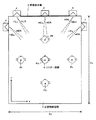
情報処理装置10では、ディスプレイ11上に画像を表示し、イヤホン装置50によって音声を出力するに当たって、仮想シアターのような仮想視聴空間を想定する。図3に、仮想視聴空間の一例を示す。
<1-1-3. Virtual viewing space: Fig. 3>
In the
この例の仮想視聴空間1は、基準面(図3の紙面に平行な面)上で見て長方形の空間で、リスナーから見て前方側に、画像表示面2、センターのスピーカ3および左右のスピーカ4,5が設置され、左右の側方の前方寄りの位置に、スピーカ6,7が設置されたものである。
The
ただし、この例のスピーカ数およびスピーカ配置位置は一例であって、スピーカ数およびスピーカ配置位置は任意に設定することができる。 However, the number of speakers and the speaker arrangement position in this example are examples, and the number of speakers and the speaker arrangement position can be arbitrarily set.
画像表示面2は、スクリーンとして投射によって、またはディスプレイとして、画像が表示される面である。
The
位置Poは、仮想視聴空間1の中心位置であり、リスナー頭部9の実線で示す状態は、リスナー頭部9が位置Poにおいて画像表示面2に正対している状態である。
The position Po is the center position of the
リスナーが位置Poから位置Pfに移動することは、実際のシアターで前方側の席に移動することに相当し、位置Poから位置Pbに移動することは、実際のシアターで後方側の席に移動することに相当する。 The movement of the listener from the position Po to the position Pf corresponds to the movement of the front seat in the actual theater, and the movement of the listener from the position Po to the position Pb moves to the rear seat in the actual theater. It corresponds to doing.
リスナーが位置Poから位置Plに移動することは、実際のシアターで左側の席に移動することに相当し、位置Poから位置Prに移動することは、実際のシアターで右側の席に移動することに相当する。 Moving the listener from position Po to position Pl is equivalent to moving to the left seat in the actual theater, and moving from position Po to position Pr is to move to the right seat in the actual theater. It corresponds to.
この仮想視聴空間1の左右方向をX軸方向、前後方向をY軸方向、基準面(図3の紙面に平行な面)に垂直な方向をZ軸方向とする。
The left-right direction of the
<1−1−4.音像定位処理:図4>
図4に、図3のように仮想視聴空間1が想定された場合の情報処理装置10の音声処理部24の音像定位処理に係る構成の一例を示す。
<1-1-4. Sound image localization processing: Fig. 4>
FIG. 4 shows an example of a configuration related to the sound image localization process of the
音声信号SC,SL,SR,SEおよびSFは、それぞれ、図3に示した仮想視聴空間1に設置された仮想のスピーカ3,4,5,6および7から出力されるチャンネルの、圧縮されているデータについては伸長した後のデジタル音声データである。
The audio signals SC, SL, SR, SE, and SF are compressed for the channels output from the
音声信号SCは、デジタルフィルタ43Lおよび43Rに供給され、音声信号SLは、デジタルフィルタ44Lおよび44Rに供給され、音声信号SRは、デジタルフィルタ45Lおよび45Rに供給される。
The audio signal SC is supplied to the
音声信号SEは、デジタルフィルタ46Lおよび46Rに供給され、音声信号SFは、デジタルフィルタ47Lおよび47Rに供給される。
The audio signal SE is supplied to the
デジタルフィルタ43Lは、スピーカ3の位置からリスナー頭部9の左耳に至る伝達関数HCLを時間領域に変換したインパルス応答を畳み込むフィルタである。
The
デジタルフィルタ43Rは、スピーカ3の位置からリスナー頭部9の右耳に至る伝達関数HCRを時間領域に変換したインパルス応答を畳み込むフィルタである。
The
デジタルフィルタ44Lは、スピーカ4の位置からリスナー頭部9の左耳に至る伝達関数HLLを時間領域に変換したインパルス応答を畳み込むフィルタである。
The
デジタルフィルタ44Rは、スピーカ4の位置からリスナー頭部9の右耳に至る伝達関数HLRを時間領域に変換したインパルス応答を畳み込むフィルタである。
The
デジタルフィルタ45Lは、スピーカ5の位置からリスナー頭部9の左耳に至る伝達関数HRLを時間領域に変換したインパルス応答を畳み込むフィルタである。
The
デジタルフィルタ45Rは、スピーカ5の位置からリスナー頭部9の右耳に至る伝達関数HRRを時間領域に変換したインパルス応答を畳み込むフィルタである。
The
デジタルフィルタ46Lは、スピーカ6の位置からリスナー頭部9の左耳に至る伝達関数HELを時間領域に変換したインパルス応答を畳み込むフィルタである。
The digital filter 46L is a filter that convolves an impulse response obtained by converting the transfer function HEL from the position of the
デジタルフィルタ46Rは、スピーカ6の位置からリスナー頭部9の右耳に至る伝達関数HERを時間領域に変換したインパルス応答を畳み込むフィルタである。
The
デジタルフィルタ47Lは、スピーカ7の位置からリスナー頭部9の左耳に至る伝達関数HFLを時間領域に変換したインパルス応答を畳み込むフィルタである。
The
デジタルフィルタ47Rは、スピーカ7の位置からリスナー頭部9の右耳に至る伝達関数HFRを時間領域に変換したインパルス応答を畳み込むフィルタである。
The
加算回路41で、デジタルフィルタ43L,44L,45L,46Lおよび47Lの出力の音声信号が加算される。加算回路42で、デジタルフィルタ43R,44R,45R,46Rおよび47Rの出力の音声信号が加算される。
The
加算回路41の出力の音声信号は、図2に示したDAC25でアナログ音声信号に変換される。その変換後の音声信号が、左音声信号として、音声増幅回路27で増幅されて、トランスデューサ61に供給される。
The audio signal output from the
加算回路42の出力の音声信号は、図2に示したDAC26でアナログ音声信号に変換される。その変換後の音声信号が、右音声信号として、音声増幅回路28で増幅されて、トランスデューサ71に供給される。
The audio signal output from the
(1−2.情報処理方法:図5〜図13)
第1の実施形態では、ディスプレイ11を移動または回転させたとき、その移動後または回転後のディスプレイ11とリスナー頭部との位置関係を仮想視聴空間1での画像表示面2とリスナー頭部との位置関係に写像するように、音像定位を制御する。
(1-2. Information processing method: FIGS. 5 to 13)
In the first embodiment, when the
<1−2−1.初期状態:図5>
このように音像定位を制御するためには、初期状態の設定が必要である。
<1-2-1. Initial state: Fig. 5>
Thus, in order to control the sound image localization, it is necessary to set an initial state.
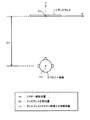
図5に、実際の視聴空間の初期状態設定時の状態の一例を示す。 FIG. 5 shows an example of a state when an actual viewing space is initially set.
リスナーは、情報処理システム100によって画像および音声を視聴するとき、自身に対してディスプレイ11が或る位置および或る方向にある状態で、操作部12での操作によって情報処理装置10に初期状態を設定させる。
When a listener views an image and sound with the information processing system 100, the listener returns an initial state to the
図5は、リスナーが、自身の正面側の自身の頭部9の位置Hoに対して或る距離Loを隔てた位置Doにディスプレイ11が存在するように情報処理装置10を手に持ち、ディスプレイ11を自身に正対させた状態で、設定操作をした場合である。
FIG. 5 shows that the listener holds the
このとき、情報処理装置10は、ディスプレイ11の画面左右方向に延長してディスプレイ11の画面と所定角度で交差する面を基準面とし、この基準面上の画面左右方向をX軸方向、これに垂直な方向をY軸方向、基準面に垂直な方向をZ軸方向とする。
At this time, the
図2に示した加速度センサ31は、このX軸方向およびY軸方向の移動の加速度を検出し、ジャイロセンサ32は、Z軸方向の回転の角速度を検出する。
The
ディスプレイ11とリスナー頭部9との初期距離Loは、任意であるが、一般に人がディスプレイを手に持ってディスプレイ画面を見るときの距離としては30cm程度である。
The initial distance Lo between the
この初期状態は、図3に示したようにリスナーが仮想視聴空間1内の所定位置、例えば中心位置Poの席で、映画などの画像および音声を視聴する状態とする。
In this initial state, as shown in FIG. 3, the listener is in a state of viewing images and sounds such as movies at a predetermined position in the
そのため、ディスプレイ11とリスナー頭部9との位置関係が初期状態とされた状態にあるときには、リスナーが仮想音源のスピーカ3〜7に対して図3に示すような位置Poおよび方向で音声を聴取するように、音像定位を制御する。
Therefore, when the positional relationship between the
<1−2−2.ディスプレイを移動させた場合:図6および図7>
第1の実施形態の第1の方法は、リスナーがディスプレイ11を、上記のX軸方向またはY軸方向に移動させた場合である。
<1-2-2. When the display is moved: FIGS. 6 and 7>
The first method of the first embodiment is a case where the listener moves the
図6に、リスナーがディスプレイ11を、上記の初期状態から、参照符号11mで示すように、X軸方向にはX軸プラス方向に距離Dxだけ移動させ、Y軸方向にはY軸マイナス方向に距離Dyだけ移動させた場合を示す。
In FIG. 6, the listener moves the
X軸プラス方向は、画面右方向であり、X軸マイナス方向は、画面左方向であり、Y軸プラス方向は、リスナー頭部9から遠ざかる方向であり、Y軸マイナス方向は、リスナー頭部9に近づく方向である。
The X axis plus direction is the right direction of the screen, the X axis minus direction is the left direction of the screen, the Y axis plus direction is the direction away from the
位置Doは、ディスプレイ11の初期位置であり、位置Dmは、ディスプレイ11の移動後の位置である。
The position Do is an initial position of the
距離Lmは、ディスプレイ11の移動後のディスプレイ11とリスナー頭部9との距離であり、初期距離Loが30cmなどというように設定されれば、図6中の式(1)によって算出することができる。
The distance Lm is the distance between the
情報処理装置10の演算制御部21は、加速度センサ31の2軸の出力の、X軸方向およびY軸方向の加速度を、それぞれ2回積分して、ディスプレイ11のX軸方向の移動距離DxおよびY軸方向の移動距離Dyを算出する。
The
さらに、情報処理装置10の演算制御部21は、移動後のディスプレイ11とリスナー頭部9との位置関係が仮想視聴空間1での画像表示面2とリスナー頭部9との位置関係に写像されるように、音像定位の処理パラメータを選択決定する。
Furthermore, the
写像変換のために、一つの方法として、X軸方向の変換率およびY軸方向の変換率を、それぞれKとして、距離Qx,Qyとして、Qx=K・Dx,Qy=K・Dy,を算出する。 For mapping conversion, as one method, the conversion rate in the X-axis direction and the conversion rate in the Y-axis direction are set as K, and distances Qx and Qy are calculated as Qx = K · Dx and Qy = K · Dy, respectively. To do.
仮想視聴空間1の範囲や、画像表示面2と中心位置Poとの距離は、実際の視聴空間でリスナーの腕を最大に伸ばせる範囲や、実際の視聴空間での上記の距離Loに比べて、十分に大きいので、変換率Kは1より大きくする。
The range of the
実際の視聴空間でディスプレイ11が、X軸プラス方向に距離Dxだけ移動し、Y軸マイナス方向に距離Dyだけ移動したことは、仮想視聴空間1ではリスナー頭部9が、X軸マイナス方向に距離Qxだけ移動し、Y軸プラス方向に距離Qyだけ移動したことに相当する。
In the actual viewing space, the
そのため、図7に示すように、仮想視聴空間1でのリスナー頭部9の位置Pmとして、中心位置Poから、X軸マイナス方向に距離Qxだけ移動し、Y軸プラス方向に距離Qyだけ移動した位置を算出する。
Therefore, as shown in FIG. 7, the position Pm of the listener's
位置Pmは、仮想視聴空間1の画像表示面2から見ると、Y軸マイナス方向に対して時計方向に、図6中の式(2)で表される角度αだけ回転した方向である。
When viewed from the
別の方法として、上記の距離Lmと角度αとから、仮想視聴空間1でのリスナー頭部9の位置Pmを算出することもできる。
As another method, the position Pm of the listener's
すなわち、この場合、画像表示面2から見て、Y軸マイナス方向に対して時計方向に角度αだけ回転した方向に、画像表示面2の左右方向の中心から、上記の距離Lmに変換率Kを乗じた距離lmだけ離れた点を、仮想視聴空間1でのリスナー頭部9の位置Pmとして算出する。
That is, in this case, the conversion rate K from the center in the left-right direction of the
変換率Kは、仮想視聴空間1のX軸方向(左右方向)の幅Cx、またはY軸方向(前後方向)の奥行きCyを考慮して決定することもできる。
The conversion rate K can also be determined in consideration of the width Cx in the X-axis direction (left-right direction) of the
例えば、人の腕の長さを50cmとし、実際の視聴空間ではディスプレイ11とリスナー頭部9との距離Lmが最大で50cmになるとする。
For example, it is assumed that the length of a person's arm is 50 cm and the distance Lm between the
この距離Lmの最大値をLmmaxとすると、奥行きCyを考慮した場合としては、
lm:Lm=Cy:Lmmax ‥‥‥(5)
すなわち、
lm=Cy×Lm/Lmmax ‥‥‥(6)
とする。
Assuming that the maximum value of the distance Lm is Lmmax, when considering the depth Cy,
lm: Lm = Cy: Lmmax (5)
That is,
lm = Cy × Lm / Lmmax (6)
And
また、幅Cxを考慮した場合としては、
lm:Lm=Cx/2:Lmmax ‥(7)
すなわち、
lm=Cx×Lm/2×Lmmax ‥(8)
とする。
In addition, when considering the width Cx,
lm: Lm = Cx / 2: Lmmax (7)
That is,
lm = Cx × Lm / 2 × Lmmax (8)
And
<1−2−3.ディスプレイを回転させた場合:図8および図9>
第1の実施形態の第2の方法は、リスナーがディスプレイ11を、上記のZ軸の回りに回転させた場合である。
<1-2-3. When the display is rotated: FIGS. 8 and 9>
The second method of the first embodiment is a case where the listener rotates the
図8に、リスナーがディスプレイ11を、図5に示した初期状態に対して、参照符号11rで示すように、上記の位置Doを回転中心としてZ軸の回りに、上方(紙面の手前側)から見て反時計方向に角度φだけ回転させた場合を示す。
In FIG. 8, the listener moves the
情報処理装置10の演算制御部21は、ジャイロセンサ32の出力の、Z軸の回りの回転の角速度を積分して、回転角φを算出する。
The
さらに、情報処理装置10の演算制御部21は、回転後のディスプレイ11とリスナー頭部9との位置関係が仮想視聴空間1での画像表示面2とリスナー頭部9との位置関係に写像されるように、音像定位の処理パラメータを選択決定する。
Further, the
具体的に、実際の視聴空間でディスプレイ11が反時計方向に角度φだけ回転したことは、仮想視聴空間1ではリスナー頭部9が時計方向に角度φだけ回転したことに相当する。
Specifically, the fact that the
そのため、この場合、図9に示すように、画像表示面2から見て、Y軸マイナス方向に対して時計方向に角度φだけ回転した方向に、画像表示面2の左右方向の中心から、上記の距離Loに変換率Kを乗じた距離loだけ離れた点を、仮想視聴空間1でのリスナー頭部9の位置Pmとして算出する。
Therefore, in this case, as shown in FIG. 9, the
リスナー頭部9の向きは、画像表示面2の左右方向の中心を向く方向とする。
The direction of the listener's
<1−2−4.ディスプレイを移動かつ回転させた場合:図10および図11>
第1の実施形態の第3の方法は、リスナーがディスプレイ11を、移動かつ回転させた場合である。
<1-2-4. When the display is moved and rotated: FIGS. 10 and 11>
The third method of the first embodiment is a case where the listener moves and rotates the
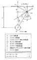
一例として、図10に、リスナーがディスプレイ11を、図5に示した初期状態から、参照符号11mrで示すように、X軸プラス方向に距離Dx、Y軸マイナス方向に距離Dy、移動させるとともに、Z軸の回りに、反時計方向に角度φだけ回転させた場合を示す。
As an example, in FIG. 10, the listener moves the
すなわち、この例は、ディスプレイ11を、図6に示したように移動させ、かつ図8に示したように回転させた場合である。
That is, this example is a case where the
この場合、図11に示すように、画像表示面2から見て、Y軸マイナス方向に対して時計方向に角度β(=φ+α)だけ回転した方向に、画像表示面2の左右方向の中心から距離lm(=K×Lm)だけ離れた点を、仮想視聴空間1でのリスナー頭部9の位置Pmとして算出する。
In this case, as shown in FIG. 11, when viewed from the
<1−2−5.演算制御の処理:図12および図13>
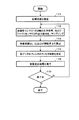
図12に、第1の実施形態で情報処理装置10の演算制御部21が実行する一連の処理の一例を示す。
<1-2-5. Processing of arithmetic control: FIGS. 12 and 13>
FIG. 12 illustrates an example of a series of processes executed by the
この例では、まずステップ111で、上記のようにリスナーの操作に基づいて初期状態を設定する。
In this example, first, in
次に、ステップ112で、加速度センサ31の2軸の出力信号、およびジャイロセンサ32の出力信号を、サンプリングし、デジタルデータに変換して、ディスプレイ11のX軸方向およびY軸方向の移動の加速度を示すデータ、およびディスプレイ11のZ軸の回りの回転の角速度を示すデータを得る。
Next, in
次に、ステップ113で、図13の式(11)、式(12)および式(13)によって、ディスプレイ11のX軸方向の移動距離Dx、Y軸方向の移動距離Dy、およびZ軸の回りの回転角φを算出する。
Next, in
次に、ステップ114で、その算出結果をもとに、図4に示したデジタルフィルタ43L,43R,44L,44R,45L,45R,46L,46R,47Lおよび47Rのフィルタ係数を決定する。
Next, in
次に、ステップ115で、音声処理部24において、その決定されたフィルタ係数によって音像定位処理を実行する。
Next, in
次に、ステップ116で、一連の処理を終了するか否かを判断し、リスナーの終了操作などによって一連の処理を終了する場合を除いて、ステップ116からステップ112に戻って、ステップ112〜115の処理を繰り返す。
Next, in
[2.第2の実施形態:図14〜図19]
第2の実施形態として、第1の実施形態のようにディスプレイを移動または回転させるだけでなく、リスナー自身も移動または回転する場合を示す。
[2. Second Embodiment: FIGS. 14 to 19]
As a second embodiment, a case where not only the display is moved or rotated as in the first embodiment but also the listener itself is moved or rotated is shown.
(2−1.システム構成:図14および図15)
第2の実施形態でも、例えば、図1に示したように、情報処理システム100は情報処理装置10およびイヤホン装置50によって構成される。
(2-1. System configuration: FIGS. 14 and 15)
Also in the second embodiment, for example, as illustrated in FIG. 1, the information processing system 100 includes the
情報処理装置10が外観的にディスプレイ11および操作部12を備えることも、第1の実施形態と同じである。
The
さらに、第2の実施形態では、イヤホン装置50は、リスナー頭部の移動または回転を検出できるセンサが取り付けられたものとして構成する。図14に、その一例を示す。 Furthermore, in 2nd Embodiment, the earphone apparatus 50 is comprised as what was attached the sensor which can detect a movement or rotation of a listener's head. An example is shown in FIG.
左イヤホン部60は、インナーフレーム62の一端側に、上記のトランスデューサ61およびグリル63が取り付けられ、他端側に、コードブッシング64が取り付けられる。
In the
左イヤホン部60の耳から出る部分には、加速度センサ65、ジャイロセンサ66およびハウジング67が取り付けられる。左イヤホン部60の耳の中に入る部分には、イヤピース69が取り付けられる。
An
右イヤホン部70は、左イヤホン部60と同様に、インナーフレーム72の一端側に、上記のトランスデューサ71およびグリル73が取り付けられ、他端側に、コードブッシング74が取り付けられる。
As with the
右イヤホン部70の耳から出る部分には、ハウジング77が取り付けられる。右イヤホン部70の耳の中に入る部分には、イヤピース79が取り付けられる。
A
加速度センサ65は、後述の基準面内の互いに直交する2つの軸(X軸およびY軸)の方向の移動の加速度を検出するものとし、ジャイロセンサ66は、その基準面に垂直な軸(Z軸)の回りの回転の角速度を検出するものとする。
The
情報処理装置10は、図15に示すように、第1の実施形態の場合の図2に示した構成に加えて、バス14に、イヤホン装置50の加速度センサ65およびジャイロセンサ66の出力信号をそれぞれデジタルデータに変換するADC35および36が接続される。
As shown in FIG. 15, in addition to the configuration shown in FIG. 2 in the case of the first embodiment, the
第2の実施形態でも、例えば、図3に示したような仮想視聴空間1を想定し、情報処理装置10の音声処理部24では、図4に示したような音像定位処理を実行する。
Also in the second embodiment, for example, assuming the
(2−2.情報処理方法:図16〜図19)
第2の実施形態でも、情報処理装置10は、リスナーの操作によって初期状態を設定する。初期状態は、例えば、図5に示した状態である。
(2-2. Information processing method: FIGS. 16 to 19)
Also in the second embodiment, the
第2の実施形態では、ディスプレイ11およびリスナー自身の移動または回転の組合せとして、
(a)ディスプレイ11を移動し、リスナー自身も頭部を移動する場合、
(b)ディスプレイ11を移動し、リスナー自身は頭部を回転させる場合、
(c)ディスプレイ11を回転させ、リスナー自身は頭部を移動する場合、
(d)ディスプレイ11を回転させ、リスナー自身も頭部を回転させる場合、
(e)ディスプレイ11を移動かつ回転させ、リスナー自身も頭部を移動かつ回転させる場合、
が存在する。
In the second embodiment, as a combination of movement or rotation of the
(A) When the
(B) When the
(C) When the
(D) When the
(E) When the
Exists.
いずれの場合も、実際の視聴空間でのディスプレイ11とリスナー頭部9との位置関係を仮想視聴空間1での画像表示面2とリスナー頭部9との位置関係に写像するように、音像定位を制御する。
In any case, the sound image localization is performed so that the positional relationship between the
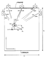
図16に、上記(e)の場合として、リスナーがディスプレイ11を移動かつ回転させるとともに、リスナー自身が頭部を移動かつ回転させた場合を示す。
FIG. 16 shows a case where the listener moves and rotates the
具体的に、ディスプレイ11は、図10に示したように移動かつ回転させ、リスナー頭部9は、X軸プラス方向に距離Hxだけ移動させ、Y軸マイナス方向に距離Hyだけ移動させ、Z軸の回りにディスプレイ11とは逆に時計方向に角度θだけ回転させた場合を示す。
Specifically, the
位置Do、距離Lo、位置Dm、距離Dx、距離Dyおよび回転角φは、図5、図6、図8および図10に示したそれと同じである。 The position Do, the distance Lo, the position Dm, the distance Dx, the distance Dy, and the rotation angle φ are the same as those shown in FIGS. 5, 6, 8, and 10.
位置Hoは、この場合にはリスナー頭部9の初期位置であり、位置Hmは、リスナー頭部9の移動後の位置である。
The position Ho is the initial position of the
ディスプレイ11のX軸方向の移動距離DxおよびY軸方向の移動距離Dyは、第1の実施形態でも示したように、加速度センサ31の2軸の出力の、X軸方向およびY軸方向の加速度を、それぞれ2回積分して算出する。
The movement distance Dx in the X-axis direction and the movement distance Dy in the Y-axis direction of the
リスナー頭部9のX軸方向の移動距離HxおよびY軸方向の移動距離Hyは、加速度センサ65の2軸の出力の、X軸方向およびY軸方向の加速度を、それぞれ2回積分して算出する。
The movement distance Hx in the X-axis direction and the movement distance Hy in the Y-axis direction of the listener's
ディスプレイ11の回転角φは、第1の実施形態でも示したように、ジャイロセンサ32の出力の角速度を積分して算出する。
The rotation angle φ of the
リスナー頭部9の回転角θは、ジャイロセンサ66の出力の角速度を積分して算出する。
The rotation angle θ of the
ディスプレイ11およびリスナー頭部9の移動後のディスプレイ11とリスナー頭部9との距離Lmは、初期距離Loが30cmなどというように設定されれば、図16中の式(3)によって算出することができる。図16中の角度αは、図16中の式(4)で表される。
The distance Lm between the
情報処理装置10の演算制御部21は、以上のような移動回転後のディスプレイ11とリスナー頭部9との位置関係が仮想視聴空間1での画像表示面2とリスナー頭部9との位置関係に写像されるように、音像定位の処理パラメータを選択決定する。
The
具体的に、実際の視聴空間でディスプレイ11が反時計方向に角度φだけ回転したことは、仮想視聴空間1ではリスナー頭部9が時計方向に角度φだけ回転したことに相当する。
Specifically, the fact that the
さらに、実際の視聴空間でリスナー頭部9が時計方向に角度θだけ回転したことは、仮想視聴空間1でもリスナー頭部9が時計方向に角度θだけ回転したことに相当する。
Further, the fact that the listener's
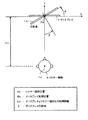
そのため、この場合、図17に示すように、画像表示面2から見て、Y軸マイナス方向に対して時計方向に角度(φ+θ)だけ回転した方向に、画像表示面2の左右方向の中心から距離lm(=K×Lm)だけ離れた点を、仮想視聴空間1でのリスナー頭部9の位置Pmとして算出する。
Therefore, in this case, as shown in FIG. 17, when viewed from the
リスナー頭部9の向きは、画像表示面2の左右方向の中心を向く方向とする。
The direction of the listener's
図18に、第2の実施形態で情報処理装置10の演算制御部21が実行する一連の処理の一例を示す。
FIG. 18 illustrates an example of a series of processes executed by the
この例では、まずステップ121で、上記のようにリスナーの操作に基づいて初期状態を設定する。
In this example, first, in
次に、ステップ122で、加速度センサ31の2軸の出力信号、ジャイロセンサ32の出力信号、加速度センサ65の2軸の出力信号、ジャイロセンサ66の出力信号を、サンプリングし、デジタルデータに変換して、ディスプレイ11のX軸方向およびY軸方向の移動の加速度を示すデータ、ディスプレイ11のZ軸の回りの回転の角速度を示すデータ、リスナー頭部9のX軸方向およびY軸方向の移動の加速度を示すデータ、およびリスナー頭部9のZ軸の回りの回転の角速度を示すデータを得る。
Next, in
次に、ステップ123で、図19の式(11)、式(12)および式(13)によって、ディスプレイ11のX軸方向の移動距離Dx、Y軸方向の移動距離Dy、およびZ軸の回りの回転角φを算出するとともに、図19の式(21)、式(22)および式(23)によって、リスナー頭部9のX軸方向の移動距離Hx、Y軸方向の移動距離Hy、およびZ軸の回りの回転角θを算出する。
Next, in
次に、ステップ124で、その算出結果をもとに、図4に示したデジタルフィルタ43L,43R,44L,44R,45L,45R,46L,46R,47Lおよび47Rのフィルタ係数を決定する。
Next, in
次に、ステップ125で、音声処理部24において、その決定されたフィルタ係数によって音像定位処理を実行する。
Next, in
次に、ステップ126で、一連の処理を終了するか否かを判断し、リスナーの終了操作などによって一連の処理を終了する場合を除いて、ステップ126からステップ122に戻って、ステップ122〜125の処理を繰り返す。
Next, in
[3.他の実施形態:図20]
図20に示すように、情報処理システム100を、ディスプレイ装置80、情報処理装置90およびイヤホン装置50によって構成してもよい。この場合、ディスプレイ装置80と情報処理装置90との接続、および情報処理装置90とイヤホン装置50との接続を、Bluetooth(登録商標)などの無線によって行うように構成すると、好適である。
[3. Other Embodiment: FIG. 20]
As illustrated in FIG. 20, the information processing system 100 may include a display device 80, an
情報処理装置90は、ホームサーバとして、ハードディスクなどに画像データや音楽データを蓄積し、画像処理、および上記の音像定位を含む音声処理を実行するものである。
As the home server, the
ディスプレイ装置80は、ディスプレイ11および操作部12を備え、ディスプレイ11の移動を検出するための加速度センサや、ディスプレイ11の回転を検出するためのジャイロセンサなどを備え、センサの出力信号を情報処理装置90に送信するものとする。
The display device 80 includes a
イヤホン装置50は、回路装置部51に、バッテリー、無線通信モジュールおよびボリュームなどを設け、第2の実施形態のようにリスナー頭部の移動または回転に対応させる場合には、左イヤホン部60または右イヤホン部70に加速度センサやジャイロセンサなどを取り付ける。
The earphone device 50 is provided with a battery, a wireless communication module, a volume, and the like in the
なお、図1に示したように情報処理システム100を情報処理装置10およびイヤホン装置50によって構成する場合でも、情報処理装置10とイヤホン装置50との接続を無線によって行うように構成してもよい。
In addition, even when the information processing system 100 is configured by the
また、トランスデューサ装置としては、イヤホン装置に限らず、ヘッドホン装置でもよい。 Further, the transducer device is not limited to the earphone device, but may be a headphone device.
主要部については図中に記述したので、ここでは省略する。 Since the main part is described in the figure, it is omitted here.
Claims (6)
このディスプレイの移動または回転を検出するためのディスプレイ用センサと、
イヤホン装置またはヘッドホン装置であるトランスデューサ装置と、
このトランスデューサ装置を装着して音声を聴取するリスナーの頭外の位置に音像を定位させるように音声信号を処理する音声処理部と、
上記ディスプレイ用センサの出力を演算して、上記ディスプレイの移動方向および移動距離、または回転方向および回転角を算出し、その算出結果に応じて、上記ディスプレイとリスナー頭部との位置関係を想定された仮想視聴空間での画像表示面とリスナー頭部との位置関係に写像するように、上記音声処理部における音声処理を制御する演算制御部と、
を備える情報処理システム。 Display,
A display sensor for detecting the movement or rotation of the display;
A transducer device that is an earphone device or a headphone device;
A sound processing unit that processes the sound signal so that the sound image is localized at a position outside the head of the listener who listens to the sound by wearing this transducer device;
The output of the display sensor is calculated to calculate the moving direction and moving distance, or the rotating direction and rotating angle of the display, and the positional relationship between the display and the listener's head is assumed according to the calculation result. An arithmetic control unit that controls audio processing in the audio processing unit so as to map to a positional relationship between the image display surface and the listener's head in the virtual viewing space;
An information processing system comprising:
上記トランスデューサ装置に取り付けられた、リスナー頭部の移動または回転を検出するためのトランスデューサ用センサを備え、
上記演算制御部は、上記ディスプレイ用センサの出力、および上記トランスデューサ用センサの出力を演算して、上記ディスプレイの移動方向および移動距離、または回転方向および回転角、および上記リスナー頭部の移動方向および移動距離、または回転方向および回転角を算出し、その算出結果に応じて、上記ディスプレイとリスナー頭部との位置関係を上記仮想視聴空間での画像表示面とリスナー頭部との位置関係に写像するように、上記音声処理部における音声処理を制御する情報処理システム。 The information processing system according to claim 1,
A transducer sensor attached to the transducer device for detecting movement or rotation of a listener's head;
The calculation control unit calculates the output of the display sensor and the output of the transducer sensor, and the movement direction and movement distance, or rotation direction and rotation angle of the display, and the movement direction of the listener head and Calculate the movement distance or rotation direction and rotation angle, and map the positional relationship between the display and the listener's head to the positional relationship between the image display surface and the listener's head in the virtual viewing space according to the calculation results. An information processing system for controlling audio processing in the audio processing unit.
当該情報処理システムは、上記ディスプレイ、上記ディスプレイ用センサ、上記音声処理部および上記演算制御部を備える情報処理装置と、上記トランスデューサ装置とによって構成された情報処理システム。 The information processing system according to claim 1,
The information processing system includes an information processing device including the display, the display sensor, the sound processing unit, and the arithmetic control unit, and the transducer device.
当該情報処理システムは、上記ディスプレイおよび上記ディスプレイ用センサを備えるディスプレイ装置と、上記トランスデューサ装置と、上記音声処理部および上記演算制御部を備える情報処理装置とによって構成された情報処理システム。 The information processing system according to claim 1,
The information processing system is an information processing system including the display device including the display and the display sensor, the transducer device, and the information processing device including the sound processing unit and the arithmetic control unit.
上記ディスプレイ用センサの出力を演算して、上記ディスプレイの移動方向および移動距離、または回転方向および回転角を算出する演算工程と、
その算出結果に応じて、上記ディスプレイとリスナー頭部との位置関係を想定された仮想視聴空間での画像表示面とリスナー頭部との位置関係に写像するように、上記音声処理部における音声処理を制御する制御工程と、
を備える情報処理方法。 A display, a display sensor for detecting the movement or rotation of the display, a transducer device that is an earphone device or a headphone device, and a sound image at a position outside the head of the listener who listens to the sound by wearing the transducer device As an information processing method executed by an information processing system including an audio processing unit that processes an audio signal so as to be localized,
A calculation step of calculating an output of the display sensor and calculating a moving direction and moving distance of the display, or a rotating direction and a rotating angle;
In accordance with the calculation result, the audio processing in the audio processing unit is mapped so as to map the positional relationship between the display and the listener's head to the positional relationship between the image display surface and the listener's head in the assumed virtual viewing space. A control process for controlling
An information processing method comprising:
上記情報処理システムは、上記トランスデューサ装置に取り付けられた、リスナー頭部の移動または回転を検出するためのトランスデューサ用センサを備え、
情報処理方法として、そのトランスデューサ用センサの出力を演算して、上記リスナー頭部の移動方向および移動距離、または回転方向および回転角を算出する演算工程を備え、
上記制御工程では、上記それぞれの演算工程での算出結果に応じて、上記ディスプレイとリスナー頭部との位置関係を上記仮想視聴空間での画像表示面とリスナー頭部との位置関係に写像するように、上記音声処理部における音声処理を制御する情報処理方法。 The information processing method according to claim 5,
The information processing system includes a transducer sensor attached to the transducer device for detecting movement or rotation of a listener's head,
As an information processing method, a calculation step of calculating an output of the transducer sensor and calculating a movement direction and a movement distance, or a rotation direction and a rotation angle of the listener head,
In the control step, the positional relationship between the display and the listener's head is mapped to the positional relationship between the image display surface and the listener's head in the virtual viewing space according to the calculation results in the respective calculation steps. An information processing method for controlling voice processing in the voice processing unit.
Priority Applications (5)
| Application Number | Priority Date | Filing Date | Title |
|---|---|---|---|
| JP2008319316A JP4849121B2 (en) | 2008-12-16 | 2008-12-16 | Information processing system and information processing method |
| US12/634,999 US8644531B2 (en) | 2008-12-16 | 2009-12-10 | Information processing system and information processing method |
| EP09252762A EP2200349B1 (en) | 2008-12-16 | 2009-12-10 | Information processing system and information processing method |
| AT09252762T ATE515899T1 (en) | 2008-12-16 | 2009-12-10 | INFORMATION PROCESSING SYSTEM AND INFORMATION PROCESSING METHOD |
| CN200910259228.1A CN101784004B (en) | 2008-12-16 | 2009-12-16 | Information processing system and information processing method |
Applications Claiming Priority (1)
| Application Number | Priority Date | Filing Date | Title |
|---|---|---|---|
| JP2008319316A JP4849121B2 (en) | 2008-12-16 | 2008-12-16 | Information processing system and information processing method |
Publications (2)
| Publication Number | Publication Date |
|---|---|
| JP2010147529A true JP2010147529A (en) | 2010-07-01 |
| JP4849121B2 JP4849121B2 (en) | 2012-01-11 |
Family
ID=42112209
Family Applications (1)
| Application Number | Title | Priority Date | Filing Date |
|---|---|---|---|
| JP2008319316A Active JP4849121B2 (en) | 2008-12-16 | 2008-12-16 | Information processing system and information processing method |
Country Status (5)
| Country | Link |
|---|---|
| US (1) | US8644531B2 (en) |
| EP (1) | EP2200349B1 (en) |
| JP (1) | JP4849121B2 (en) |
| CN (1) | CN101784004B (en) |
| AT (1) | ATE515899T1 (en) |
Cited By (5)
| Publication number | Priority date | Publication date | Assignee | Title |
|---|---|---|---|---|
| JP2018005526A (en) * | 2016-06-30 | 2018-01-11 | 株式会社リコー | Information processor and program |
| US11438721B2 (en) | 2018-09-28 | 2022-09-06 | Jvckenwood Corporation | Out-of-head localization system, filter generation device, method, and program |
| JP2023530479A (en) * | 2020-06-17 | 2023-07-18 | ボーズ・コーポレーション | Spatialized audio for mobile peripherals |
| US12495266B2 (en) | 2018-04-04 | 2025-12-09 | Bose Corporation | Systems and methods for sound source virtualization |
| DE112024002283T5 (en) | 2023-05-29 | 2026-03-19 | Sony Group Corporation | INFORMATION PROCESSING DEVICE, INFORMATION PROCESSING SYSTEM, INFORMATION PROCESSING METHOD AND PROGRAM |
Families Citing this family (23)
| Publication number | Priority date | Publication date | Assignee | Title |
|---|---|---|---|---|
| US9332372B2 (en) * | 2010-06-07 | 2016-05-03 | International Business Machines Corporation | Virtual spatial sound scape |
| US8587631B2 (en) * | 2010-06-29 | 2013-11-19 | Alcatel Lucent | Facilitating communications using a portable communication device and directed sound output |
| US9237393B2 (en) * | 2010-11-05 | 2016-01-12 | Sony Corporation | Headset with accelerometers to determine direction and movements of user head and method |
| US8183997B1 (en) * | 2011-11-14 | 2012-05-22 | Google Inc. | Displaying sound indications on a wearable computing system |
| US10009706B2 (en) | 2011-12-07 | 2018-06-26 | Nokia Technologies Oy | Apparatus and method of audio stabilizing |
| WO2013105413A1 (en) * | 2012-01-11 | 2013-07-18 | ソニー株式会社 | Sound field control device, sound field control method, program, sound field control system, and server |
| JP6028357B2 (en) * | 2012-03-22 | 2016-11-16 | ソニー株式会社 | Head mounted display and surgical system |
| US9271103B2 (en) * | 2012-03-29 | 2016-02-23 | Intel Corporation | Audio control based on orientation |
| US9420386B2 (en) * | 2012-04-05 | 2016-08-16 | Sivantos Pte. Ltd. | Method for adjusting a hearing device apparatus and hearing device apparatus |
| CN103037301B (en) * | 2012-12-19 | 2014-11-05 | 武汉大学 | Convenient adjustment method for restoring range information of acoustic images |
| CN103052018B (en) * | 2012-12-19 | 2014-10-22 | 武汉大学 | Audio-visual distance information recovery method |
| JP2014143470A (en) * | 2013-01-22 | 2014-08-07 | Sony Corp | Information processing unit, information processing method, and program |
| EP3515055A1 (en) * | 2013-03-15 | 2019-07-24 | Dolby Laboratories Licensing Corp. | Normalization of soundfield orientations based on auditory scene analysis |
| JP2015027015A (en) * | 2013-07-29 | 2015-02-05 | ソニー株式会社 | Information presentation apparatus and information processing system |
| CN104581541A (en) * | 2014-12-26 | 2015-04-29 | 北京工业大学 | Locatable multimedia audio-visual device and control method thereof |
| CN106154231A (en) * | 2016-08-03 | 2016-11-23 | 厦门傅里叶电子有限公司 | The method of sound field location in virtual reality |
| US10089063B2 (en) * | 2016-08-10 | 2018-10-02 | Qualcomm Incorporated | Multimedia device for processing spatialized audio based on movement |
| CN106375928A (en) * | 2016-11-24 | 2017-02-01 | 深圳市佳都实业发展有限公司 | Master-control advertisement player, auxiliary advertisement player and advertisement player array with 3D sound filed function |
| US10277973B2 (en) | 2017-03-31 | 2019-04-30 | Apple Inc. | Wireless ear bud system with pose detection |
| CN108958459A (en) * | 2017-05-19 | 2018-12-07 | 深圳市掌网科技股份有限公司 | Display methods and system based on virtual location |
| JP7342451B2 (en) * | 2019-06-27 | 2023-09-12 | ヤマハ株式会社 | Audio processing device and audio processing method |
| CN110769351A (en) * | 2019-10-29 | 2020-02-07 | 歌尔科技有限公司 | Control method of audio device, and storage medium |
| CN115706883A (en) * | 2021-08-06 | 2023-02-17 | 北京小米移动软件有限公司 | Audio signal processing method and device |
Citations (11)
| Publication number | Priority date | Publication date | Assignee | Title |
|---|---|---|---|---|
| WO1995022235A1 (en) * | 1994-02-14 | 1995-08-17 | Sony Corporation | Device for reproducing video signal and audio signal |
| JPH0970094A (en) * | 1995-08-31 | 1997-03-11 | Sony Corp | Headphone equipment |
| JPH0993700A (en) * | 1995-09-28 | 1997-04-04 | Sony Corp | Video and audio playback device |
| JPH10230899A (en) * | 1997-02-24 | 1998-09-02 | Motoya Takeyama | Man-machine interface of aerospace aircraft |
| JP2002209300A (en) * | 2001-01-09 | 2002-07-26 | Matsushita Electric Ind Co Ltd | Sound image localization device, conference device using the sound image localization device, mobile phone, audio reproduction device, audio recording device, information terminal device, game machine, communication and broadcasting system |
| JP2006165845A (en) * | 2004-12-06 | 2006-06-22 | Alpine Electronics Inc | Video-audio apparatus |
| JP2006186904A (en) * | 2004-12-28 | 2006-07-13 | Mitsumi Electric Co Ltd | Headset device |
| WO2006107074A1 (en) * | 2005-04-05 | 2006-10-12 | Matsushita Electric Industrial Co., Ltd. | Portable terminal |
| JP2006294032A (en) * | 2002-09-05 | 2006-10-26 | Sony Computer Entertainment Inc | Display system, display control device, display apparatus, display method, and user interface device |
| JP2006295313A (en) * | 2005-04-06 | 2006-10-26 | Sony Corp | Information processing apparatus and method, recording medium, and program |
| JP2008219759A (en) * | 2007-03-07 | 2008-09-18 | Navitime Japan Co Ltd | Portable media content reproduction system, portable media content reproduction apparatus and media content distribution server |
Family Cites Families (5)
| Publication number | Priority date | Publication date | Assignee | Title |
|---|---|---|---|---|
| JPH09284676A (en) * | 1996-04-15 | 1997-10-31 | Sony Corp | Video and audio processing method and video display device synchronized with body movement |
| JP3994296B2 (en) | 1998-01-19 | 2007-10-17 | ソニー株式会社 | Audio playback device |
| GB2359177A (en) | 2000-02-08 | 2001-08-15 | Nokia Corp | Orientation sensitive display and selection mechanism |
| JP3880561B2 (en) * | 2002-09-05 | 2007-02-14 | 株式会社ソニー・コンピュータエンタテインメント | Display system |
| US8005245B2 (en) * | 2004-09-16 | 2011-08-23 | Panasonic Corporation | Sound image localization apparatus |
-
2008
- 2008-12-16 JP JP2008319316A patent/JP4849121B2/en active Active
-
2009
- 2009-12-10 EP EP09252762A patent/EP2200349B1/en active Active
- 2009-12-10 AT AT09252762T patent/ATE515899T1/en not_active IP Right Cessation
- 2009-12-10 US US12/634,999 patent/US8644531B2/en active Active
- 2009-12-16 CN CN200910259228.1A patent/CN101784004B/en active Active
Patent Citations (11)
| Publication number | Priority date | Publication date | Assignee | Title |
|---|---|---|---|---|
| WO1995022235A1 (en) * | 1994-02-14 | 1995-08-17 | Sony Corporation | Device for reproducing video signal and audio signal |
| JPH0970094A (en) * | 1995-08-31 | 1997-03-11 | Sony Corp | Headphone equipment |
| JPH0993700A (en) * | 1995-09-28 | 1997-04-04 | Sony Corp | Video and audio playback device |
| JPH10230899A (en) * | 1997-02-24 | 1998-09-02 | Motoya Takeyama | Man-machine interface of aerospace aircraft |
| JP2002209300A (en) * | 2001-01-09 | 2002-07-26 | Matsushita Electric Ind Co Ltd | Sound image localization device, conference device using the sound image localization device, mobile phone, audio reproduction device, audio recording device, information terminal device, game machine, communication and broadcasting system |
| JP2006294032A (en) * | 2002-09-05 | 2006-10-26 | Sony Computer Entertainment Inc | Display system, display control device, display apparatus, display method, and user interface device |
| JP2006165845A (en) * | 2004-12-06 | 2006-06-22 | Alpine Electronics Inc | Video-audio apparatus |
| JP2006186904A (en) * | 2004-12-28 | 2006-07-13 | Mitsumi Electric Co Ltd | Headset device |
| WO2006107074A1 (en) * | 2005-04-05 | 2006-10-12 | Matsushita Electric Industrial Co., Ltd. | Portable terminal |
| JP2006295313A (en) * | 2005-04-06 | 2006-10-26 | Sony Corp | Information processing apparatus and method, recording medium, and program |
| JP2008219759A (en) * | 2007-03-07 | 2008-09-18 | Navitime Japan Co Ltd | Portable media content reproduction system, portable media content reproduction apparatus and media content distribution server |
Cited By (7)
| Publication number | Priority date | Publication date | Assignee | Title |
|---|---|---|---|---|
| JP2018005526A (en) * | 2016-06-30 | 2018-01-11 | 株式会社リコー | Information processor and program |
| US12495266B2 (en) | 2018-04-04 | 2025-12-09 | Bose Corporation | Systems and methods for sound source virtualization |
| US11438721B2 (en) | 2018-09-28 | 2022-09-06 | Jvckenwood Corporation | Out-of-head localization system, filter generation device, method, and program |
| JP2023530479A (en) * | 2020-06-17 | 2023-07-18 | ボーズ・コーポレーション | Spatialized audio for mobile peripherals |
| JP7667187B2 (en) | 2020-06-17 | 2025-04-22 | ボーズ・コーポレーション | Spatialized Audio for Mobile Peripheral Devices |
| US12549920B2 (en) | 2020-06-17 | 2026-02-10 | Bose Corporation | Spatialized audio relative to a peripheral device |
| DE112024002283T5 (en) | 2023-05-29 | 2026-03-19 | Sony Group Corporation | INFORMATION PROCESSING DEVICE, INFORMATION PROCESSING SYSTEM, INFORMATION PROCESSING METHOD AND PROGRAM |
Also Published As
| Publication number | Publication date |
|---|---|
| CN101784004B (en) | 2013-03-06 |
| EP2200349B1 (en) | 2011-07-06 |
| EP2200349A1 (en) | 2010-06-23 |
| ATE515899T1 (en) | 2011-07-15 |
| US8644531B2 (en) | 2014-02-04 |
| JP4849121B2 (en) | 2012-01-11 |
| CN101784004A (en) | 2010-07-21 |
| US20100150355A1 (en) | 2010-06-17 |
Similar Documents
| Publication | Publication Date | Title |
|---|---|---|
| JP4849121B2 (en) | Information processing system and information processing method | |
| US10397728B2 (en) | Differential headtracking apparatus | |
| CN101662720B (en) | Sound processing apparatus, sound image localized position adjustment method and video processing apparatus | |
| JP5676487B2 (en) | Head tracking for mobile applications | |
| EP3599772B1 (en) | Shape-shifting headphones | |
| US20130259244A1 (en) | Hearing device with an inertial measurement unit | |
| US9769585B1 (en) | Positioning surround sound for virtual acoustic presence | |
| KR20150003528A (en) | Method and apparatus for user interface by sensing head movement | |
| EP3599773B1 (en) | Shape-shifting headphones for conveying information | |
| CN108028999A (en) | For providing device, the method and computer program of audio reproduction | |
| JP2025106569A (en) | Information processing method, program, and sound reproducing device | |
| US20240381051A1 (en) | Acoustic reproduction method, recording medium, and acoustic reproduction system | |
| WO2024247561A1 (en) | Information processing device, information processing system, information processing method, and program | |
| KR102613035B1 (en) | Earphone with sound correction function and recording method using it | |
| CN115002613A (en) | Earphone (Headset) | |
| JP2026509896A (en) | Distributed head tracking | |
| CN120826919A (en) | Distributed head tracking | |
| JP2024056580A (en) | Information processing device, control method thereof, and program |
Legal Events
| Date | Code | Title | Description |
|---|---|---|---|
| A977 | Report on retrieval |
Free format text: JAPANESE INTERMEDIATE CODE: A971007 Effective date: 20101013 |
|
| A131 | Notification of reasons for refusal |
Free format text: JAPANESE INTERMEDIATE CODE: A131 Effective date: 20101021 |
|
| A521 | Request for written amendment filed |
Free format text: JAPANESE INTERMEDIATE CODE: A523 Effective date: 20101214 |
|
| A131 | Notification of reasons for refusal |
Free format text: JAPANESE INTERMEDIATE CODE: A131 Effective date: 20110705 |
|
| A521 | Request for written amendment filed |
Free format text: JAPANESE INTERMEDIATE CODE: A523 Effective date: 20110829 |
|
| TRDD | Decision of grant or rejection written | ||
| A01 | Written decision to grant a patent or to grant a registration (utility model) |
Free format text: JAPANESE INTERMEDIATE CODE: A01 Effective date: 20110920 |
|
| A01 | Written decision to grant a patent or to grant a registration (utility model) |
Free format text: JAPANESE INTERMEDIATE CODE: A01 |
|
| A61 | First payment of annual fees (during grant procedure) |
Free format text: JAPANESE INTERMEDIATE CODE: A61 Effective date: 20111003 |
|
| R151 | Written notification of patent or utility model registration |
Ref document number: 4849121 Country of ref document: JP Free format text: JAPANESE INTERMEDIATE CODE: R151 |
|
| FPAY | Renewal fee payment (event date is renewal date of database) |
Free format text: PAYMENT UNTIL: 20141028 Year of fee payment: 3 |
|
| R250 | Receipt of annual fees |
Free format text: JAPANESE INTERMEDIATE CODE: R250 |
|
| R250 | Receipt of annual fees |
Free format text: JAPANESE INTERMEDIATE CODE: R250 |
|
| R250 | Receipt of annual fees |
Free format text: JAPANESE INTERMEDIATE CODE: R250 |
|
| R250 | Receipt of annual fees |
Free format text: JAPANESE INTERMEDIATE CODE: R250 |
|
| R250 | Receipt of annual fees |
Free format text: JAPANESE INTERMEDIATE CODE: R250 |
|
| R250 | Receipt of annual fees |
Free format text: JAPANESE INTERMEDIATE CODE: R250 |
|
| R250 | Receipt of annual fees |
Free format text: JAPANESE INTERMEDIATE CODE: R250 |