JP2010147522A - Remote control transmitter-receiver - Google Patents
Remote control transmitter-receiver Download PDFInfo
- Publication number
- JP2010147522A JP2010147522A JP2008319236A JP2008319236A JP2010147522A JP 2010147522 A JP2010147522 A JP 2010147522A JP 2008319236 A JP2008319236 A JP 2008319236A JP 2008319236 A JP2008319236 A JP 2008319236A JP 2010147522 A JP2010147522 A JP 2010147522A
- Authority
- JP
- Japan
- Prior art keywords
- remote control
- control transmitter
- receiver
- transmitter
- code
- Prior art date
- Legal status (The legal status is an assumption and is not a legal conclusion. Google has not performed a legal analysis and makes no representation as to the accuracy of the status listed.)
- Pending
Links
Images

Classifications
-
- G—PHYSICS
- G08—SIGNALLING
- G08C—TRANSMISSION SYSTEMS FOR MEASURED VALUES, CONTROL OR SIMILAR SIGNALS
- G08C17/00—Arrangements for transmitting signals characterised by the use of a wireless electrical link
-
- H—ELECTRICITY
- H04—ELECTRIC COMMUNICATION TECHNIQUE
- H04B—TRANSMISSION
- H04B1/00—Details of transmission systems, not covered by a single one of groups H04B3/00 - H04B13/00; Details of transmission systems not characterised by the medium used for transmission
- H04B1/06—Receivers
- H04B1/16—Circuits
- H04B1/20—Circuits for coupling gramophone pick-up, recorder output, or microphone to receiver
- H04B1/202—Circuits for coupling gramophone pick-up, recorder output, or microphone to receiver by remote control
-
- G—PHYSICS
- G08—SIGNALLING
- G08C—TRANSMISSION SYSTEMS FOR MEASURED VALUES, CONTROL OR SIMILAR SIGNALS
- G08C2201/00—Transmission systems of control signals via wireless link
- G08C2201/20—Binding and programming of remote control devices
-
- G—PHYSICS
- G08—SIGNALLING
- G08C—TRANSMISSION SYSTEMS FOR MEASURED VALUES, CONTROL OR SIMILAR SIGNALS
- G08C2201/00—Transmission systems of control signals via wireless link
- G08C2201/90—Additional features
- G08C2201/92—Universal remote control
Landscapes
- Engineering & Computer Science (AREA)
- Computer Networks & Wireless Communication (AREA)
- Signal Processing (AREA)
- Physics & Mathematics (AREA)
- General Physics & Mathematics (AREA)
- Selective Calling Equipment (AREA)
- Details Of Television Systems (AREA)
Abstract
Description
本発明は、主に各種電子機器の遠隔操作に用いられるリモコン送受信装置に関するものである。 The present invention relates to a remote control transmission / reception apparatus mainly used for remote control of various electronic devices.
近年、テレビやビデオ、ディスクレコーダ等の各種電子機器の高機能化が進むなか、これらを遠隔操作するリモコン送受信装置においても、所定の操作によってリモコン送信機に様々な機器の操作コードを記憶させ、一つのリモコン送信機で異なる機器を遠隔操作することが可能な、いわゆるラーニング機能を備えたリモコン送信機が多く用いられるようになっている。 In recent years, as advanced functions of various electronic devices such as televisions, videos, disk recorders and the like have advanced, even in a remote control transmission / reception device that remotely controls these, operation codes of various devices are stored in a remote control transmitter by a predetermined operation, A remote control transmitter having a so-called learning function that can remotely control different devices with one remote control transmitter is often used.
このような従来のリモコン送信機について、図7を用いて説明する。 Such a conventional remote control transmitter will be described with reference to FIG.
図7は従来のリモコン送信機の平面図であり、同図において、1は略箱状で絶縁樹脂製のケースで、このケース1上面や側面には、下方にスイッチ接点が設けられた複数の操作キー2Aや2B等が上下動または摺動可能に突出して、操作手段2が形成されている。
FIG. 7 is a plan view of a conventional remote control transmitter. In FIG. 7,
そして、ケース1内には上下面に複数の配線パターンが形成された配線基板(図示せず)が収納され、この配線基板の上下面に実装された各種電子部品によって送信手段3や受信手段4、制御手段5が各々形成されて、第一のリモコン送信機6が構成されている。
A wiring board (not shown) having a plurality of wiring patterns formed on the upper and lower surfaces is housed in the
また、7は第二のリモコン送信機で、第一のリモコン送信機6と同様に、ケース8上面や側面に複数の操作キー9Bや9C等の操作手段9が設けられると共に、このケース8内には各種電子部品によって送信手段10や、例えばA社のテレビの操作コードを記憶した制御手段11が各々形成されている。
以上の構成において、第一のリモコン送信機6の操作手段2のラーニング用の、例えば操作キー2Aを押圧操作した後、例えば再生用の「△」が表示された操作キー2Bを押圧操作すると、これらの下方のスイッチ接点の電気的接離が行われ、これを制御手段5が検出して、第一のリモコン送信機6が操作コードを記憶する状態となる。
In the above configuration, after pressing the
次に、第一のリモコン送信機6の操作キー2Aを押圧操作したままで、これに対向させた第二のリモコン送信機7の「△」が表示された操作キー9Bを押圧操作すると、この下方のスイッチ接点の電気的接離を制御手段11が検出して、送信手段10から再生用の操作コードがリモコン信号として送信される。
Next, when the
そして、これを第一のリモコン送信機6の受信手段4が受信すると共に、制御手段5がこの再生用の操作コードを、押圧操作したままの再生用の「△」が表示された操作キー2Aに割り当てて記憶する。
Then, the reception means 4 of the first
また、続いて、第一のリモコン送信機6の、例えば選局用の「1」が表示された操作キー2Cを押圧操作し、このままで第二のリモコン送信機7の「1」が表示された操作キー9Cを押圧操作すると、送信手段10から選局「1」用の操作コードが送信される。
Subsequently, the operation key 2C of the first
そして、これを第一のリモコン送信機6が受信し、制御手段5がこの選局「1」用の操作コードを、選局用の「1」が表示された操作キー2Cに割り当てて記憶する。
Then, the first
さらに、この後、第一のリモコン送信機6の各々の操作キー2を押圧操作した状態で、第二のリモコン送信機7の各々の操作キー9を順次押圧操作してリモコン信号を送信することによって、これらの各操作コードが第一のリモコン送信機6の制御手段5に記憶される。
Further, after that, in a state where each
そして、この第一のリモコン送信機6をA社のテレビに向け、例えば操作キー2Cを押圧操作すると、この下方のスイッチ接点の電気的接離を制御手段5が検出して、送信手段3から選局用の操作コードがリモコン信号として送信され、例えばテレビのチャンネルが「1」に切り換わる。
Then, when the first
つまり、A社のテレビの操作コードを記憶した第二のリモコン送信機7を、第一のリモコン送信機6に対向させて配置し、各々の操作キー2と9の押圧操作を交互に順次行うことによって、第一のリモコン送信機6がA社のテレビを遠隔操作することが可能な状態、すなわちラーニングされた状態となるように構成されているものであった。
In other words, the second
なお、この出願の発明に関連する先行技術文献情報としては、例えば、特許文献1が知られている。
しかしながら、上記従来のリモコン送信機においては、ラーニングさせたい第一のリモコン送信機6と、所定の操作コードを記憶した第二のリモコン送信機7の、各々の操作キー2と9を交互に順次押圧操作してラーニングを行っているため、操作が煩雑で手間がかかると共に、操作キーの押し間違い等の誤操作も起こし易いという課題があった。
However, in the conventional remote control transmitter, the
本発明は、このような従来の課題を解決するものであり、簡易な操作で、確実な遠隔操作が可能なリモコン送受信装置を提供することを目的とする。 The present invention solves such a conventional problem, and an object of the present invention is to provide a remote control transmission / reception device capable of reliable remote operation with a simple operation.
上記目的を達成するために本発明は、以下の構成を有するものである。 In order to achieve the above object, the present invention has the following configuration.
本発明の請求項1に記載の発明は、第一のリモコン送信機の操作手段の所定の操作に応じて、リモコン受信機が記憶した自らの操作コードを、第一のリモコン送信機に送信するようにしてリモコン送受信装置を構成したものであり、第一のリモコン送信機の所定の操作によって、リモコン受信機から操作コードを受信して記憶を行うことができるため、誤操作も生じづらく簡易な操作で、確実な操作コードの記憶と、この記憶した操作コードによる遠隔操作が可能なリモコン送受信装置を得ることができるという作用を有する。 According to the first aspect of the present invention, the operation code stored by the remote control receiver is transmitted to the first remote control transmitter in response to a predetermined operation of the operation means of the first remote control transmitter. In this way, the remote control transmission / reception device is configured, and an operation code can be received and stored from the remote control receiver by a predetermined operation of the first remote control transmitter. Thus, it is possible to obtain a remote control transmission / reception apparatus capable of storing a reliable operation code and performing a remote operation using the stored operation code.
請求項2に記載の発明は、請求項1記載の発明において、第二のリモコン送信機を設けると共に、この第二のリモコン送信機の操作コードを、リモコン受信機を介して第一のリモコン送信機が受信するものであり、リモコン受信機が記憶した操作コードに加え、第二のリモコン送信機の操作コードも簡易な操作で、ラーニングを行うことができるという作用を有する。 According to a second aspect of the present invention, in the first aspect of the invention, a second remote control transmitter is provided, and an operation code of the second remote control transmitter is transmitted to the first remote control via the remote control receiver. In addition to the operation code stored in the remote control receiver, the operation code of the second remote control transmitter also has an effect that learning can be performed with a simple operation.
以上のように本発明によれば、簡易な操作で、確実な遠隔操作が可能なリモコン送受信装置を実現できるという有利な効果が得られる。 As described above, according to the present invention, it is possible to obtain an advantageous effect that it is possible to realize a remote control transmission / reception device capable of reliable remote operation with a simple operation.
以下、本発明の実施の形態について、主に電波方式のものを例に図1〜図6を用いて説明する。 Hereinafter, an embodiment of the present invention will be described with reference to FIGS.
(実施の形態1)
実施の形態1を用いて、本発明の特に請求項1記載の発明について説明する。
(Embodiment 1)
The first aspect of the present invention will be described with reference to the first embodiment.
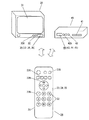
図1は本発明の第1の実施の形態によるリモコン送受信装置のブロック回路図、図2は同模式図であり、同図において、21は略箱状でポリスチレンやABS等の絶縁樹脂製のケースで、このケース21上面や側面には、下方にスイッチ接点が設けられたゴムや絶縁樹脂製の複数の操作キー22Aや22B等が、上下動可能に突出して操作手段22が形成されている。
FIG. 1 is a block circuit diagram of a remote control transmission / reception apparatus according to a first embodiment of the present invention. FIG. 2 is a schematic diagram. In FIG. 1,
そして、ケース21内には上下面に銅箔等によって複数の配線パターンが形成された、紙フェノールやガラス入りエポキシ等の配線基板(図示せず)が収納されると共に、この配線基板の上下面に実装されたアンテナ等によって送信手段23や受信手段24、マイコン等の電子部品によって制御手段25が、各々形成されて、第一のリモコン送信機26が構成されている。
The
また、30はテレビ等の電子機器で、この前面には液晶表示素子やブラウン管等の表示手段31が設けられると共に、後方にスイッチ接点が形成された複数の操作手段32、アンテナ等の送信手段33や受信手段34、マイコン等の制御手段35から形成された、第一のリモコン受信機36が収納されている。
さらに、40はビデオやディスクレコーダ等の電子機器で、この前面にはテープやディスク等を収納する駆動手段41が設けられると共に、電子機器30と同様に、複数の操作手段42や送信手段43、受信手段44、制御手段45から形成された第二のリモコン受信機46が収納され、これら第一のリモコン送信機26と第一のリモコン受信機36、あるいは第二のリモコン受信機46によって、リモコン送受信装置が構成されている。
Further, 40 is an electronic device such as a video or disk recorder, and a drive means 41 for storing a tape, a disk or the like is provided on the front surface thereof, and, like the
なお、このように離れた位置や家具等の遮蔽物があった場合でも遠隔操作が可能なように、電波を用いて遠隔操作を行うリモコン送受信装置の場合、赤外線方式のもの等に比べ通信範囲が広いため、室内に置かれた他の機器、あるいは他の部屋の機器にまで電波が届き、意図しない機器まで誤って操作されてしまう場合がある。 In addition, in the case of a remote control transmission / reception device that performs remote operation using radio waves so that remote control is possible even when there is a shield such as a remote location or furniture, the communication range compared to infrared type devices etc. Therefore, there are cases where radio waves reach other devices placed in the room or devices in other rooms, and even unintended devices are erroneously operated.
このため、使用前に操作手段22や32、42の所定の操作を行い、所定の認証コード等を設定して、第一のリモコン送信機26と第一のリモコン受信機36、あるいは第二のリモコン受信機46のみが、各々一組のペアとして操作可能となる設定、いわゆるペアリングを行った後に、通常の遠隔操作が行われるようになっている。
Therefore, a predetermined operation of the operation means 22, 32, 42 is performed before use, a predetermined authentication code is set, and the first
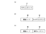
つまり、以上の構成において、第一のリモコン受信機36のペアリング用の、例えば操作キー32Aを押圧操作した後、第一のリモコン送信機26のペアリング用の、例えば操作キー22Aを押圧操作すると、これらの下方のスイッチ接点の電気的接離が行われ、これを制御手段35や25が検出して、図3(a)の信号構成図に示すような、第一のリモコン受信機36との間で設定されているペアリングコードL1が、第一のリモコン送信機26の送信手段23から電波として送信される。
That is, in the above configuration, after pressing the
そして、これを第一のリモコン受信機36の受信手段34が受信すると共に、制御手段35がこのリモコン信号のペアリングコードL1が設定されたものと同一であるか否かを判定し、一致した場合には、図3(b)に示すような、認証コードM1の後に、記憶した自らの操作コードの全てと複数の操作キー22への割り当てを示すキーアドレスマップN1が付加されたリモコン信号を、送信手段33から送信する。
And this is received by the
さらに、このリモコン信号を第一のリモコン送信機26の受信手段24が受信し、制御手段25がこの認証コードM1とキーアドレスマップN1を記憶することによって、第一のリモコン送信機26と第一のリモコン受信機36のペアリングが終了する。
Further, the remote control signal is received by the
つまり、第一のリモコン送信機26と第一のリモコン受信機36が、各々一組のペアとして操作可能となる認証コードM1の設定、すなわちペアリングと、第一のリモコン送信機26がテレビ等の電子機器30を遠隔操作するための操作コードの記憶、すなわちラーニングが同時に行われるように構成されている。
That is, the setting of the authentication code M1 that allows the first
また、このようにペアリングとラーニングが行われた第一のリモコン送信機26を、電子機器30に向け、例えば選局用の「1」が表示された操作キー22Bを押圧操作すると、この下方のスイッチ接点の電気的接離を制御手段25が検出して、図3(c)に示すような、記憶した認証コードM1の後に、記憶したキーアドレスマップN1から選択した、選局「1」用の操作コードN2が付加されたリモコン信号を送信手段23から送信する。
Further, when the first
そして、これを第一のリモコン受信機36の受信手段34が受信すると共に、制御手段35がこのリモコン信号の認証コードM1が設定されたものと同一であるか否かを判定し、一致した場合には、操作コードN2に応じた電子機器30の操作、例えばテレビに表示された表示手段31の画面の、チャンネル「1」への切り換えが行われる。
When this is received by the receiving means 34 of the first
なお、この時、受信した認証コードM1が設定されたものと異なる場合には、制御手段35がペアリングされたものとは別のリモコン送信機からのリモコン信号であると判定し、操作コードN2に応じた選局の切り換え等の遠隔操作は行われないようになっている。 At this time, if the received authentication code M1 is different from the set one, the control means 35 determines that it is a remote control signal from a remote control transmitter different from the paired one, and the operation code N2 Remote operation such as switching of channel selection according to is not performed.
また、この第一のリモコン送信機26と第二のリモコン受信機46のペアリングとラーニングを行う場合には、先ず、第二のリモコン受信機46のペアリング用の操作キー42Aを押圧操作した後、第一のリモコン送信機26のラーニング用の操作キー22Cとペアリング用の操作キー22Aを押圧操作すると、上記の場合と同様に、ペアリングコードが送信手段23から電波として送信される。
When pairing and learning of the first
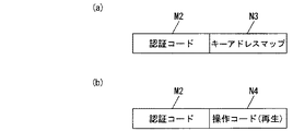
そして、これを第二のリモコン受信機46の受信手段44が受信すると共に、制御手段45がこのペアリングコードを判定し、一致した場合には、図4(a)の信号構成図に示すような、電子機器30とは異なる認証コードM2の後に、記憶した自らの操作コードの全てと複数の操作キー22への割り当てを示すキーアドレスマップN3が付加されたリモコン信号を、送信手段43から送信する。
Then, this is received by the receiving means 44 of the second
さらに、このリモコン信号を第一のリモコン送信機26の受信手段24が受信し、制御手段25がこの認証コードM2とキーアドレスマップN3を記憶することによって、第一のリモコン送信機26と第二のリモコン受信機46のペアリングが終了する。
Further, the remote control signal is received by the receiving means 24 of the first
つまり、この場合にも、第一のリモコン送信機26と第二のリモコン受信機46が各々一組のペアとして操作可能となるペアリングと、第一のリモコン送信機26がビデオやディスクレコーダ等の電子機器40を遠隔操作するためのラーニングが、同時に行われるように構成されている。
That is, also in this case, the first
また、このようにペアリングとラーニングが行われた第一のリモコン送信機26を、電子機器40に向け、ラーニング用の操作キー22Cを押圧操作した後、例えば再生用の「△」が表示された操作キー22Dを押圧操作すると、図4(b)に示すような、認証コードM2の後に、キーアドレスマップN3から選択した、再生用の操作コードN4が付加されたリモコン信号が送信手段23から送信される。
Further, the first
そして、これを第二のリモコン受信機46の受信手段44が受信し、制御手段45が認証コードM2を判定して、一致した場合には、操作コードN4に応じた電子機器40の操作、例えばビデオやディスクレコーダの駆動手段41が駆動して、テープやディスク等の再生が行われる。
Then, this is received by the receiving means 44 of the second
つまり、第一のリモコン送信機26の操作キー22Aや22Cといった、一つか二つの操作キーを押圧操作して、第一のリモコン受信機36や第二のリモコン受信機46と送受信を行うことで、これらとのペアリングを行うと共に、この時、同時にこれらが記憶した操作コードを制御手段25が記憶することによって、第一のリモコン送信機26へのラーニングが行われるように構成されている。
That is, by pressing one or two operation keys such as the
すなわち、操作キーの押し間違い等の誤操作も生じづらく、簡易な操作で第一のリモコン送信機26のラーニングが可能になると共に、このラーニングされた第一のリモコン送信機26によって、電子機器30や40の確実な遠隔操作が行えるようになっている。
That is, an erroneous operation such as a mistake in pressing an operation key is not likely to occur, and the first
このように本実施の形態によれば、第一のリモコン送信機26の操作手段22の所定の操作に応じて、第一のリモコン受信機36や第二のリモコン受信機46が記憶した自らの操作コードを、第一のリモコン送信機26に送信することによって、操作キー22Aや22Cといった少ない操作キーを押圧操作するだけで、第一のリモコン送信機26へのラーニングが行えるため、誤操作も生じづらく簡易な操作で、確実な操作コードの記憶と、この記憶した操作コードによる遠隔操作が可能なリモコン送受信装置を得ることができるものである。
As described above, according to the present embodiment, the first
(実施の形態2)
実施の形態2を用いて、本発明の特に請求項2記載の発明について説明する。
(Embodiment 2)
A second embodiment of the present invention, particularly the invention according to
なお、実施の形態1の構成と同一構成の部分には同一符号を付して、詳細な説明を省略する。
In addition, the same code | symbol is attached | subjected to the part of the structure same as the structure of
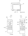
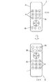
図5は本発明の第2の実施の形態によるリモコン送受信装置の模式図であり、同図において、第一のリモコン送信機26に操作手段22や送信手段23、受信手段24、制御手段25が形成されていることや、操作手段32や送信手段33、受信手段34、制御手段35が形成された第一のリモコン受信機36が、表示手段31が設けられたテレビ等の電子機器30に収納されていることは、実施の形態1の場合と同様である。
FIG. 5 is a schematic diagram of a remote control transmission / reception apparatus according to the second embodiment of the present invention. In FIG. 5, the operation means 22, the transmission means 23, the reception means 24, and the control means 25 are added to the first
また、56は第二のリモコン送信機で、第一のリモコン送信機26と同様に、ケース51の上面や側面に操作手段52が形成されると共に、ケース51内にはアンテナ等によって送信手段53や受信手段54、マイコン等の電子部品によって制御手段55が、各々形成されている。
そして、この第二のリモコン送信機56の制御手段55には、例えばA社のテレビである電子機器30とは別の、例えばB社のテレビの操作コードが記憶され、この第二のリモコン送信機56と第一のリモコン送信機26、第一のリモコン受信機36によって、リモコン送受信装置が構成されている。
The control means 55 of the second
なお、このような第一のリモコン送信機26や第二のリモコン送信機56と第一のリモコン受信機36が、使用前に操作手段22や52、32の所定の操作によって各々ペアリングされることは、実施の形態1の場合と同様であるため説明を省略し、以下、第一のリモコン送信機26へのラーニングについて説明する。
The first
以上の構成において、第二のリモコン送信機56の所定の操作コードを第一のリモコン送信機26に記憶させる場合、先ず、第一のリモコン送信機26のセット用の、例えば操作キー22Eを所定時間、例えば2秒間押圧操作すると、この下方のスイッチ接点の電気的接離が行われ、これを制御手段25が検出してセットモードとなる。
In the above configuration, when the predetermined operation code of the second
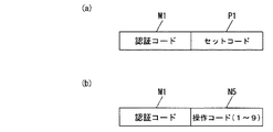
次に、ラーニング用の操作キー22Fを押圧操作してから、操作コードを割り当てたい操作キー、例えば選局用の「1」〜「9」が表示された操作キー22を順番に押圧操作した後、再び操作キー22Eを押圧操作すると、これを制御手段25が検出して、図6(a)の信号構成図に示すような、第一のリモコン受信機36との間で設定された認証コードM1の後に、セットコードP1が付加されたリモコン信号が、送信手段23から電波として送信される。
Next, after pressing the learning operation key 22F, the operation keys to which an operation code is to be assigned, for example, the
そして、これを第一のリモコン受信機36の受信手段34が受信すると共に、制御手段35がこのリモコン信号の認証コードM1が設定されたものと同一であるか否かを判定し、一致した場合には、制御手段35がセットモードとなる。
When this is received by the receiving means 34 of the first
また、この後、第二のリモコン送信機56の、第一のリモコン送信機26に記憶させたい操作キー、例えば選局用の「1」〜「9」が表示された操作キー52を順番に押圧操作すると、この下方のスイッチ接点の電気的接離が行われ、これを制御手段55が検出して、図6(b)に示すような、認証コードM1の後に操作コードN5が付加されたリモコン信号が、送信手段53から送信される。
Thereafter, the operation keys to be stored in the first
そして、これを第一のリモコン受信機36の受信手段34が受信した後、制御手段35がこのリモコン信号を送信手段33から送信し、これを第一のリモコン送信機26の受信手段24が受信すると共に、制御手段25がこの操作コードを「1」〜「9」の操作キー22に割り当てて記憶することによって、第二のリモコン送信機56から第一のリモコン送信機26への、操作コードのラーニングが終了する。
Then, after this is received by the receiving means 34 of the first
つまり、第一のリモコン送信機26の所定の操作キー22の操作によって、第一のリモコン受信機36をセットモードに設定すると共に、第二のリモコン送信機56から所定の操作コードを第一のリモコン受信機36へ送信し、これを第一のリモコン受信機36を介して、第一のリモコン送信機26が受信し記憶することによって、第一のリモコン受信機36が記憶した操作コードに加え、第二のリモコン送信機56の操作コードも、第一のリモコン送信機26にラーニングできるように構成されている。
That is, by operating the
すなわち、実施の形態1の場合と同様にして、操作手段22の所定の操作によってA社のテレビである電子機器30と、ペアリングとラーニングを同時に行った後、第二のリモコン送信機56からB社のテレビの操作コードを、第一のリモコン受信機36を介してラーニングさせることによって、第一のリモコン送信機26一つで、2社のテレビの遠隔操作を行うことが可能なようになっている。
That is, in the same manner as in the first embodiment, after the pairing and learning are performed simultaneously with the
なお、以上のように複数の機器の操作コードを記憶した第一のリモコン送信機26の、所定の操作コードを削除したい場合には、先ず、例えばラーニング用の操作キー22Fを押圧操作して、削除したい操作コードを選択した後、削除用の操作キー22Gを所定時間、例えば5秒間押圧操作すると、これらの下方のスイッチ接点の電気的接離を制御手段25が検出して、例えば操作キー22Fに割り当てられたB社のテレビの操作コードが削除される。
When the predetermined operation code of the first
つまり、第一のリモコン送信機26の操作手段22の所定の操作によって、記憶した所定の操作コードを削除することができるため、制御手段25の記憶容量をそれ程大きなものとする必要はなくなり、比較的安価なマイコンで制御手段25を形成することができる。
That is, since the stored predetermined operation code can be deleted by a predetermined operation of the
なお、以上の説明では、第二のリモコン送信機56の所定の操作コード、例えば選局用の「1」〜「9」を第一のリモコン送信機26にラーニングさせる構成について説明したが、実施の形態1の場合と同様に、操作コードの全てと複数の操作キー22への割り当てを一括して第二のリモコン送信機56から送信し、これを第一のリモコン受信機36を介して、第一のリモコン送信機26が受信し記憶するようにしてもよい。
In the above description, a configuration has been described in which the first
このように本実施の形態によれば、第二のリモコン送信機56を設けると共に、この第二のリモコン送信機56の操作コードを、第一のリモコン受信機36を介して第一のリモコン送信機26が受信することによって、第一のリモコン受信機36が記憶した操作コードに加え、第二のリモコン送信機56の操作コードも簡易な操作でラーニングを行うことができるため、確実な操作コードの記憶と、この記憶した操作コードによる遠隔操作が可能なリモコン送受信装置を得ることができるものである。
As described above, according to the present embodiment, the second
なお、以上の説明では、構成を判り易くするために、認証コードM1やM2と操作コードN1〜N5、あるいはペアリングコードL1やセットコードP1というように、リモコン信号として一つまたは二つのコードが、第一のリモコン送信機26や第二のリモコン送信機56と、第一のリモコン受信機36や第二のリモコン受信機46の間で送受信される構成として説明したが、実際にはこれらに機器やモデル毎に決められたヘッダコード等の、様々なコードが付加されたリモコン信号を用いて、一般的には送受信が行われている。
In the above description, in order to make the configuration easy to understand, one or two codes are used as remote control signals such as authentication codes M1 and M2 and operation codes N1 to N5, or pairing code L1 and set code P1. In the above description, the first
また、以上の説明では、主に電波を用いて送受信を行う構成のリモコン送受信装置について説明したが、アンテナに代えて、発光ダイオードや受光素子等によって送信手段23や受信手段24等を形成し、赤外線をリモコン信号として用いる構成のものとしても、本発明の実施は可能である。 In the above description, the remote control transmission / reception apparatus configured to mainly transmit / receive using radio waves has been described, but instead of the antenna, the transmission means 23, the reception means 24, etc. are formed by light emitting diodes, light receiving elements, etc. The present invention can be implemented even with a configuration using infrared rays as a remote control signal.
本発明によるリモコン送受信装置は、簡易な操作で、確実な遠隔操作が可能なものが得られ、主に各種電子機器の遠隔操作用として有用である。 The remote control transmission / reception apparatus according to the present invention is capable of reliable remote operation with a simple operation, and is useful mainly for remote control of various electronic devices.
21 ケース
22 操作手段
22A、22B、22C、22D、22E、22F、22G 操作キー
23 送信手段
24 受信手段
25 制御手段
26 第一のリモコン送信機
30 電子機器
31 表示手段
32 操作手段
32A 操作キー
33 送信手段
34 受信手段
35 制御手段
36 第一のリモコン受信機
40 電子機器
41 駆動手段
42 操作手段
42A 操作キー
43 送信手段
44 受信手段
45 制御手段
46 第二のリモコン受信機
51 ケース
52 操作手段
53 送信手段
54 受信手段
55 制御手段
56 第二のリモコン送信機
21
Claims (2)
Priority Applications (2)
| Application Number | Priority Date | Filing Date | Title |
|---|---|---|---|
| JP2008319236A JP2010147522A (en) | 2008-12-16 | 2008-12-16 | Remote control transmitter-receiver |
| US12/632,902 US8314728B2 (en) | 2008-12-16 | 2009-12-08 | Remote control system |
Applications Claiming Priority (1)
| Application Number | Priority Date | Filing Date | Title |
|---|---|---|---|
| JP2008319236A JP2010147522A (en) | 2008-12-16 | 2008-12-16 | Remote control transmitter-receiver |
Publications (1)
| Publication Number | Publication Date |
|---|---|
| JP2010147522A true JP2010147522A (en) | 2010-07-01 |
Family
ID=42239846
Family Applications (1)
| Application Number | Title | Priority Date | Filing Date |
|---|---|---|---|
| JP2008319236A Pending JP2010147522A (en) | 2008-12-16 | 2008-12-16 | Remote control transmitter-receiver |
Country Status (2)
| Country | Link |
|---|---|
| US (1) | US8314728B2 (en) |
| JP (1) | JP2010147522A (en) |
Cited By (1)
| Publication number | Priority date | Publication date | Assignee | Title |
|---|---|---|---|---|
| JP3197643U (en) * | 2014-11-25 | 2015-05-28 | 訊舟科技股▲ふん▼有限公司Edimax Technology Co.,Ltd. | Remote security monitoring device having monitoring function and remote control function |
Families Citing this family (11)
| Publication number | Priority date | Publication date | Assignee | Title |
|---|---|---|---|---|
| US11769398B2 (en) | 2005-09-08 | 2023-09-26 | Universal Electronics Inc. | System and method for widget-assisted setup of a universal remote control |
| US7907222B2 (en) | 2005-09-08 | 2011-03-15 | Universal Electronics Inc. | System and method for simplified setup of a universal remote control |
| US9852615B2 (en) | 2011-03-25 | 2017-12-26 | Universal Electronics Inc. | System and method for facilitating appliance control via a smart device |
| US9088663B2 (en) * | 2008-04-18 | 2015-07-21 | Universal Electronics Inc. | System for appliance control via a network |
| US10198935B2 (en) * | 2009-12-08 | 2019-02-05 | Universal Electronics Inc. | System and method for simplified activity based setup of a controlling device |
| US9019435B2 (en) | 2011-09-22 | 2015-04-28 | Universal Electronics Inc. | System and method for configuring controlling device functionality |
| US11756412B2 (en) | 2011-10-28 | 2023-09-12 | Universal Electronics Inc. | Systems and methods for associating services and/or devices with a voice assistant |
| US11295603B2 (en) | 2011-10-28 | 2022-04-05 | Universal Electronics Inc. | System and method for optimized appliance control |
| US9734707B2 (en) * | 2012-01-09 | 2017-08-15 | Universal Electronics Inc. | Features for use with a multi-sided controlling device |
| CN105741525B (en) * | 2016-02-24 | 2019-10-01 | 北京小米移动软件有限公司 | Processing method, device and the equipment of remote controler binding |
| US10560844B2 (en) | 2017-03-15 | 2020-02-11 | International Business Machines Corporation | Authentication of users for securing remote controlled devices |
Family Cites Families (9)
| Publication number | Priority date | Publication date | Assignee | Title |
|---|---|---|---|---|
| US6791467B1 (en) * | 2000-03-23 | 2004-09-14 | Flextronics Semiconductor, Inc. | Adaptive remote controller |
| JP2003174685A (en) | 2001-12-05 | 2003-06-20 | Matsushita Electric Ind Co Ltd | Remote control transmitter and transmission system using the same |
| GB0229700D0 (en) * | 2002-12-19 | 2003-01-29 | Koninkl Philips Electronics Nv | Remote control system and authentication method |
| US8223001B2 (en) * | 2005-07-19 | 2012-07-17 | Marvell International Ltd. | Two way remote control |
| US8659400B2 (en) * | 2006-09-05 | 2014-02-25 | Universal Electronics Inc. | System and method for configuring the remote control functionality of a portable device |
| JP2008263308A (en) * | 2007-04-10 | 2008-10-30 | Sony Corp | Remote controller, electronic device and remote control system |
| DE102007060808A1 (en) * | 2007-09-01 | 2009-03-05 | Maquet Gmbh & Co. Kg | Arrangement and method for providing at least one operating function of a remote control for operating a device |
| JP5117816B2 (en) * | 2007-10-24 | 2013-01-16 | フリースケール セミコンダクター インコーポレイテッド | Information management server for remote operation device, information management method for remote operation device, information management program for remote operation device, and remote operation device |
| WO2010021542A2 (en) * | 2008-08-19 | 2010-02-25 | Eldolab Holding B.V. | Configurable light fixture, configurable lighting system and method for configuring a lighting system |
-
2008
- 2008-12-16 JP JP2008319236A patent/JP2010147522A/en active Pending
-
2009
- 2009-12-08 US US12/632,902 patent/US8314728B2/en not_active Expired - Fee Related
Cited By (1)
| Publication number | Priority date | Publication date | Assignee | Title |
|---|---|---|---|---|
| JP3197643U (en) * | 2014-11-25 | 2015-05-28 | 訊舟科技股▲ふん▼有限公司Edimax Technology Co.,Ltd. | Remote security monitoring device having monitoring function and remote control function |
Also Published As
| Publication number | Publication date |
|---|---|
| US8314728B2 (en) | 2012-11-20 |
| US20100149017A1 (en) | 2010-06-17 |
Similar Documents
| Publication | Publication Date | Title |
|---|---|---|
| JP2010147522A (en) | Remote control transmitter-receiver | |
| JP4187037B2 (en) | Remote control system | |
| EP2262227B1 (en) | Image display device and operation method thereof | |
| CN100562078C (en) | Remote control, device operating system and remote control method | |
| US20050151886A1 (en) | Remote controller | |
| EP3285494B1 (en) | Display device and system and method for controlling power of the same | |
| EP2682934A1 (en) | Image processing apparatus and control method thereof | |
| CN100394763C (en) | As an input device for the remote control | |
| JP2010021815A (en) | Remote control transmitter/receiver | |
| JP3692883B2 (en) | Remote control transmitter and its inspection method | |
| US20160156956A1 (en) | Display device | |
| KR100941060B1 (en) | Control system and method of learning system using RF remote control learned through virtual IR / RF remote control | |
| JP2011130149A (en) | Remote control transmitter | |
| JP2010028703A (en) | Remote control transmission reception apparatus | |
| JP2007013929A (en) | Remote controller for remote control, equipment operating system and remote control method for remote control | |
| US20120050510A1 (en) | Three-dimensional image glasses and electronic equipment | |
| JP2013135307A (en) | Remote control device and video data processing system | |
| US9100626B2 (en) | Video processing apparatus and control method thereof | |
| JP2010178252A (en) | Remote control transmitter | |
| KR960015179B1 (en) | Function input device and method of touch panel remote controller | |
| JP2010154430A (en) | Remote control transmitting/receiving apparatus | |
| KR101822967B1 (en) | Multimedia playing system using wifi transmitter-receiver and method thereof | |
| JP2008252326A (en) | Connection information recognition system of external apparatus connected to electronic equipment and its recognition method | |
| US20140368623A1 (en) | Display apparatus providing multi-view mode and method for controlling the same | |
| KR100490259B1 (en) | The portable remote controller |