JP2010146845A - Lighting system - Google Patents
Lighting system Download PDFInfo
- Publication number
- JP2010146845A JP2010146845A JP2008322595A JP2008322595A JP2010146845A JP 2010146845 A JP2010146845 A JP 2010146845A JP 2008322595 A JP2008322595 A JP 2008322595A JP 2008322595 A JP2008322595 A JP 2008322595A JP 2010146845 A JP2010146845 A JP 2010146845A
- Authority
- JP
- Japan
- Prior art keywords
- discharge tube
- neon tube
- neon
- tube
- lighting device
- Prior art date
- Legal status (The legal status is an assumption and is not a legal conclusion. Google has not performed a legal analysis and makes no representation as to the accuracy of the status listed.)
- Granted
Links
Images
Landscapes
- Arrangement Of Elements, Cooling, Sealing, Or The Like Of Lighting Devices (AREA)
- Discharge-Lamp Control Circuits And Pulse- Feed Circuits (AREA)
Abstract
【課題】 本発明は、複数のネオン管を近接して設け、高周波で点灯しかつ調光する場合に、管状部に沿って明るさにムラを生じることがなく、安定した調光点灯が可能な照明装置を提供することを目的とするものである。
【解決手段】 本実施例の照明装置1は、ネオン管10間に位置し、ネオン管10の電極5間に沿って延出し、ネオン管10から発生する漏れ電流を遮断する近接導体からなる遮蔽壁30を設け、その遮蔽壁30は、ネオン管10の断面直径の少なくとも半分以上であって、ネオン管10の断面直径の全てが隠れない高さ位置に反射板20から上方に突出した上壁31を設けたので、一方のネオン管10からの漏れ電流を、他方のネオン管10に流出させることなく遮断することができる。また、ネオン管10毎に発光色が区画されることなく、隣接するネオン管10の発光色を混じり合わせて調光制御するこができる。
【選択図】図1PROBLEM TO BE SOLVED: To provide stable dimming lighting without causing unevenness in brightness along a tubular portion when a plurality of neon tubes are provided close to each other and are lit at high frequency and dimmed. It is an object to provide a simple lighting device.
A lighting device 1 according to the present embodiment is located between neon tubes 10, extends along electrodes 5 of the neon tube 10, and is a shield made of a proximity conductor that blocks a leakage current generated from the neon tube 10. A wall 30 is provided, and the shielding wall 30 is an upper wall that protrudes upward from the reflector 20 at a height that is at least half the cross-sectional diameter of the neon tube 10 and does not hide all of the cross-sectional diameter of the neon tube 10. Since 31 is provided, the leakage current from one neon tube 10 can be cut off without flowing into the other neon tube 10. Further, the light emission color can be controlled by mixing the light emission colors of the adjacent neon tubes 10 without dividing the light emission color for each neon tube 10.
[Selection] Figure 1
Description
本発明は、複数の放電管を近接して設け、その放電管を高周波で点灯制御させ、かつ調光を可能にする照明装置に関するものである。 The present invention relates to an illuminating device in which a plurality of discharge tubes are provided close to each other, lighting control of the discharge tubes is performed at a high frequency, and light control is possible.
従来から、出願人は特許文献1に示すようなネオン管とそのネオン管に電力を供給するトランスとを一体的に構成し、室内外の壁面等に掛けて使用する照明装置を提案してきた。
これら従来の照明装置1の内部構造を図7(A)に示す。色の異なるネオン管10a、10b、10cが複数本設けられ、そのネオン管10は、反射板20の上方に設けられた把持具4によって把持され、固定されている。反射板20の下方には、ネオン管10に電力を供給するトランス3が設けられている。ネオン管10の両端の湾曲した屈曲部11には、トランス3から延びた配線2と接続された電極5が設置されており、反射板20の下方には配線2が垂れないように配線止め9が固定されている。
Conventionally, the applicant has proposed an illuminating device in which a neon tube as shown in
The internal structure of these
このようにして、照明装置1は、複数のネオン管10a、10b、10cとトランス3とを一つのユニットとして反射板20に取付け、全体的に小型となるように設計されている。
そして、照明装置1は、図示しないコントローラによりネオン管10の電流を調整することで、ネオン管10の調光を行っている。これら照明装置1は、複数のネオン管10から発する光の明るさを調光することで、多彩な光の演出をすることができ、店舗やビル等のネオンサイン又は演出用の照明として利用されている。
Thus, the
And the
しかしながら、従来の照明装置1では、ネオン管10の左端付近を拡大した図7(B)に示すように、ネオン管10bを調光した場合、明るさを絞っていくと、電流が減少し、ネオン管間(10b,10c)に電位差が発生する。そして、2つのネオン管10が隣接していることから、一つのネオン管10cの一方の電極5から他方の電極5へ至るまえに、隣のネオン管10bに高周波の漏れ電流が隣のネオン管10bに引き寄せられ、図7(B)に示す点線のようにネオン管10cからネオン管10bに漏れ電流が発生してしまい、互いのネオン管10の点灯状態が不安定になり、ちらつきや立ち切れを起こすという問題がある。
However, in the
このような問題を解決するために、従来から以下のような発明が提案されている。
例えば、特許文献2及び特許文献3に見られるように、ネオン管の湾曲した最外周部には、アルミテープでの近接導体を設け、幅は放電路内の陽光柱の径より細く形成し、調光により陽光柱が細くなっても、近接導体に引き寄せることにより、ちらつきを防止する発明が開示されている。
また、隣接した蛍光管によって発生する漏れ電流に対する対策として、特許文献4に見られるような発明が開示されている。その発明は、屈曲形放電灯を高周波で点灯しかつ調光可能に構成した放電灯点灯装置が開示されており、屈曲形放電灯の電極側となる一端に対して、屈曲形放電灯の他端の端部側に補助導体を設ける構成により、深い調光を行った時に電極近くで発生していた漏れ電流のエネルギー全部が補助導体に引き付けられる形で管路中を通ることになり、屈曲形放電灯の両電極と端部の間で管路方向に沿って生じていた明るさの不均一を無くすことを開示している。
In order to solve such problems, the following inventions have been proposed conventionally.
For example, as seen in
Further, an invention as disclosed in
しかしながら、これら発明のうちネオン管の外周に沿って近接導体を付設するような前者の発明では、ネオン管同士の距離の方が近い場合にはネオン管からの漏れ電流の影響を受けてしまうという問題が発生する。
また、隣接する放電管からの影響を受けないように、電極に対面する反対側の端部に近接導体を設ける後者の発明では、放電管全体の長さが長くなってしまうと電極から近接導体までの距離が長くなってしまい、電流を引きつけることができなくなり、漏れ電流の影響をなくすことは困難となるという問題が発生する。
また、全体を近接導体で覆ってしまうと、例えば隣接する赤色系のネオン管と青色系のネオン管との色を混ぜて発光色として使用したい場合に、各ネオン管が区画されると色を混ぜ合わせて使用することが困難になるという問題が発生する。
However, among these inventions, in the former invention in which the proximity conductor is provided along the outer periphery of the neon tube, when the distance between the neon tubes is closer, it is affected by the leakage current from the neon tube. A problem occurs.
Further, in the latter invention in which the proximity conductor is provided at the opposite end facing the electrode so as not to be affected by the adjacent discharge tube, if the length of the entire discharge tube is increased, the proximity conductor is separated from the electrode. This causes a problem that it becomes difficult to eliminate the influence of the leakage current because the distance to the time becomes longer, it becomes impossible to attract current.
Also, if the entire conductor is covered with adjacent conductors, for example, if you want to mix the colors of adjacent red neon tubes and blue neon tubes and use them as emission colors, the colors will change as each neon tube is partitioned. The problem that it becomes difficult to mix and use occurs.
そこで、本発明は上記の問題に鑑み、複数のネオン管又は蛍光管等の放電管を近接して設け、高周波で点灯し、かつ調光して使用する場合に、管状部に沿って明るさにムラを生じることがなく、安定した調光点灯が可能な照明装置を提供することを目的とするものである。 Therefore, in view of the above problems, the present invention provides a plurality of discharge tubes such as neon tubes or fluorescent tubes close to each other, lights up at a high frequency, and adjusts the brightness along the tubular portion. It is an object of the present invention to provide an illumination device capable of stable dimming and lighting without causing unevenness.
請求項1記載の照明装置(例えば、本実施の形態の照明装置1に相当する)は、複数の放電管(例えば、本実施の形態のネオン管10に相当し、EEFL管・蛍光管等であってもよい)を近接して設け、前記放電管の電極(例えば、本実施の形態の電極5に相当する)に高周波の電力を供給して前記放電管を点灯し、かつ調光する構成とした照明装置であって、前記放電管の下方に、前記放電管の光を上方へ反射する板状の反射板(例えば、本実施の形態の反射板20に相当する)を設け、前記放電管間に位置し、前記放電管の前記電極間に沿って延出し、前記放電管から発生する漏れ電流を遮断する金属からなる遮蔽壁(例えば、本実施の形態の遮蔽壁30に相当する)を設けたことを特徴とする。
The lighting device according to claim 1 (for example, corresponding to the
以上の構成により、一方の放電管からの漏れ電流を、他方の放電管に流出するのを遮断することができる。従って、本発明の照明装置は調光制御を行ったとしても放電管のちらつきや立ち切れを起こすことはない。 With the above configuration, leakage current from one discharge tube can be blocked from flowing to the other discharge tube. Therefore, the lighting device of the present invention does not cause flickering or breakage of the discharge tube even if dimming control is performed.
請求項2記載の照明装置において、前記遮蔽壁は、前記放電管の断面直径の少なくとも半分以上であって、前記放電管の断面直径の全てが隠れない高さ位置まで前記反射板から上方に突出した上壁(例えば、本実施の形態の上壁31に相当する)を設けたことを特徴とする。
3. The lighting device according to
以上の構成により、放電管毎に発光色が区画されることなく、隣接する放電管の発光色を混じり合わせて調光制御するこができる。 With the above configuration, the light emission color can be controlled by mixing the light emission colors of the adjacent discharge tubes without dividing the light emission color for each discharge tube.
請求項3記載の照明装置において、前記放電管は、両端を屈曲して設け、その屈曲した先端に前記電極を備え、前記遮蔽壁は、少なくとも前記電極が全て隠れるとともに、前記放電管の断面直径の少なくとも半分以上が隠れる高さ位置まで前記反射板から下方に突出した下端壁(例えば、本実施の形態の下端壁32に相当する)を設けたことを特徴とする。
4. The lighting device according to
以上の構成により、少なくとも最も漏れ電流の影響を受けやすい電極を全て隠れる位置まで遮蔽することで確実に漏れ電流を遮断することが出来る。従って、本発明の照明装置は調光制御を行ったとしても放電管のちらつきや立ち切れを起こすことはない。 With the above configuration, at least the electrodes that are most susceptible to the leakage current are shielded to the position where they are hidden, so that the leakage current can be reliably cut off. Therefore, the lighting device of the present invention does not cause flickering or breakage of the discharge tube even if dimming control is performed.
請求項4記載の照明装置において、前記遮蔽壁は、前記反射板の上方中央に長手方向に亘り、前記放電管の断面直径の少なくとも半分以上であって、前記放電管の断面直径の全てが隠れない高さ位置まで前記反射板から上方に突出した中央壁(例えば、本実施の形態の中央壁33に相当する)を設けたことを特徴とする。
5. The lighting device according to
以上の構成により、一方の放電管からの漏れ電流を、他方の放電管に流出させることく遮断することができる。従って、本発明の照明装置は調光制御を行ったとしても放電管のちらつきや立ち切れを起こすことはない。 With the above configuration, the leakage current from one discharge tube can be blocked without flowing out to the other discharge tube. Therefore, the lighting device of the present invention does not cause flickering or breakage of the discharge tube even if dimming control is performed.
請求項5記載の照明装置において、前記放電管は、前記反射板と対面する位置に、長手方向に亘って前記放電管の半径よりも幅が小さなアルミテープ(例えば、本実施の形態のアルミテープ40に相当する)を付設したことを特徴とする。
6. The lighting device according to
以上の構成により、一本の放電管の電極間で放電した電荷を近接導体となるアルミテープで他方の電極から一方の電極まで導くことができるのでき、放電を安定させることができる。従って、本発明の照明装置は調光制御を行ったとしても放電管のちらつきや立ち切れを起こすことはない。 With the above configuration, the electric charge discharged between the electrodes of one discharge tube can be guided from the other electrode to the one electrode with the aluminum tape serving as the adjacent conductor, and the discharge can be stabilized. Therefore, the lighting device of the present invention does not cause flickering or breakage of the discharge tube even if dimming control is performed.
本発明の照明装置は、複数の放電管を近接して設け、高周波で点灯しかつ調光する場合に、ネオン管の管状に沿って明るさにムラを生じることがなく、安定した調光点灯が可能となる。 The lighting device of the present invention is provided with a plurality of discharge tubes close to each other, and when lighting and dimming at a high frequency, there is no unevenness in brightness along the tube of the neon tube, and stable dimming lighting Is possible.
以下に、本発明を実施するための最良の形態を図1乃至図5に基づいて説明する。
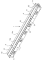
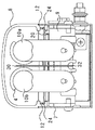
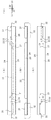
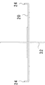
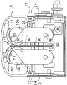
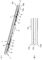
図1は、本実施形態の照明装置1のカバー8を外した状態を表した斜視図である。図2は、本実施形態の照明装置1を側方から見た端面図である。図3(A)は、本実施形態の照明装置1における反射板20の平面図である。図3(B)は、本実施形態の照明装置1における反射板20の正面図である。図3(C)は、本実施形態の照明装置1における反射板20の底面図である。図3(D)は、本実施形態の照明装置1における反射板20の右側面図であり、右側面図と左側面図は対称に現れており、左側面図の記載は省略した。図4は、本実施形態の照明装置1における反射板20を拡大した右側面図である。図5は、本実施形態の照明装置1におけるネオン管10の屈曲部11の断面図である。尚、上述した従来例の図7で説明した同じ構成は同じ符号が付してある。
The best mode for carrying out the present invention will be described below with reference to FIGS.
FIG. 1 is a perspective view showing a state in which the
図1及び図2に示すように照明装置1は、一面を開口した箱状の筐体7と、その開口を覆うように形成された乳白色や透明の透過性のカバー8と、ネオン管10やトランス3を固定する板状の反射板20と、放電により発光するネオンガスを封入したネオン管10とを設けている。
筐体7内部には、ネオン管10に電力を供給する図示しないトランス3と、ネオン管10の両端の湾曲した屈曲部11には、トランス3から延びた配線2と接続された電極5が設置されており、反射板20の下方には配線2が垂れないように配線止め9が固定されている。
As shown in FIG.1 and FIG.2, the illuminating
Inside the
ネオン管10は、2本設けられており、発光する色が異なっている。ネオン管10は、管内壁に蛍光物質を塗布するなどして様々な発光色を得られるようにしたり、また、ネオン管10のガラス管を着色することで発光色を変えることができる。ネオン管10は、反射板20に固定された樹脂性の把持具4によって把持され、固定れている。
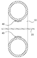
図5に示すように、ネオン管10は、電極5間に電流を導くために、反射板20に対面する位置であり、電極5間に沿って延出し、近接導体の一つとするアルミテープ40をネオン管6の外周に付設している。アルミテープ40の幅は、ネオン管10の半径よりも小さくなっている。
また、照明装置1は、図示しないコントローラで、ネオン管10の電極5間に供給される電流を変化させることで調光を行い、多彩な光の演出をすることができ、店舗やビル等のネオンサイン又は演出用の照明として利用することができる。
Two
As shown in FIG. 5, the
In addition, the
図2乃至図4に示すように、反射板20は、ネオン管10が発光する光を反射するように白色の塗料が塗布された板状に設けられている。反射板20の側端は、上方へ延出した嵌合片24が設けられており、その嵌合片24は、カバー8の下端の断面コ字状の嵌合部12と嵌合するように設けられている。そのため、カバー8は、この反射板20に嵌合することで固定される。
反射板20には、トランス3をビス等で固定するための孔となるトランス固定孔21と、把持具4を挿入固定するための孔となる把持具固定孔22と、配線止め9をビス等で固定するため孔となる配線止め固定孔23とが穿設されている。
As shown in FIGS. 2 to 4, the reflecting
In the
反射板20の中央には、漏れ電流の干渉を防ぐためネオン管10の間を区画するように近接導体としての金属性の遮蔽壁30が設けられており、その遮蔽壁30は、上壁31と、下端壁32と、中央壁33とから構成されている。
上壁31は、反射板20の中央に位置し、断面L字状に形成され、ネオン管10に沿って延出し、反射板20の両端に取り付けられている。上壁31の先端が、ネオン管10断面直径の少なくとも半分以上にあり、ネオン管10の断面直径の全てが隠れない高さ位置まで、反射板20から上方に向かって延出されている。
中央壁33は、反射板20の中央に位置し、断面L字状に形成され、ネオン管10に沿って延出し、反射板20の中央に取り付けられている。中央壁31の先端が、上壁31と同様にネオン管10の断面直径の少なくとも半分以上にあり、ネオン管10の断面直径の全てが隠れない高さ位置まで、反射板20から上方に向かって延出されている。
In the center of the
The
The
下端壁32は、反射板20の中央に位置し、断面がL字状であって、ネオン管10の屈曲部11に沿ってL字状に形成され、反射板20裏面の両端に取り付けられている。下端壁32は、反射板20よりも上方にある部分を、上壁31と同様な高さ位置まで延出しており、ネオン管10の断面直径の少なくとも半分以上にあり、ネオン管10の断面直径の全てが隠れない高さ位置まで、反射板20から上方に向かって延出されている。
更に、下端壁32は、反射板20よりも下方にある部分を、少なくとも電極5を全て隠れる位置にあって、ネオン管10の断面直径の少なくとも半分以上の高さ位置まで、反射板20から上方に向かって延出されている。
The
Further, the
図1、図5及び図6に基づいて、本実施形態の照明装置1の作用について説明する。
ネオン管10は、近接して設けられており、ネオン管10bを調光し暗く絞っていくと、電流が絞られ、そのままの明るさを保ったネオン管10bの方が高電位となるが、遮蔽壁30が設けられているために、高電位となっている漏れ電流(図6の点線Rの矢印)は、壁30に引きつけられ、他のネオン管10bに引き寄せられることはなく反射板20にアースされる。従って、ネオン管10同士の漏れ電流が干渉し合う事はない。
特に、電極5の全体を近接導体の下端壁32で仕切ることでネオン管10同士の漏れ電流が干渉し合う事はない。
更には、ネオン管10は、電極5間に電流を導くために、反射板20に対面する位置であり、電極5間に沿って延出し、近接導体の一つとするアルミテープ40をネオン管6の外周に付設しているため、一方の電極5から他方の電極5まで電荷を安定して運ぶことが出来るようになる。従って、照明装置1は、ちらつきや立ち消えの発生が抑えられる。
Based on FIG.1, FIG5 and FIG.6, the effect | action of the illuminating
The
In particular, the leakage current between the
Further, the
上壁31又は中央壁33は、ネオン管10の断面直径の少なくとも半分以上にあり、ネオン管10の断面直径の全てが隠れない高さ位置まで、反射板20から上方に向かって延出されているので、漏れ電流の遮断を行うのはもちろん、ネオン管10の上端の高さ位置まで壁を設けて区画する場合に比較して、照明装置1は、異なる色を発光するネオン管10の発光色を調和した状態で、外部に照射することができる。
例えば、図6に示すように、ネオン管10aが青の光b1を発光するとした場合には、青の光b1は、b2の位置まで届く(実線の矢印)。次に、ネオン管10bが赤の光r1を発光するとした場合には、赤の光r1は、r2の位置まで届く(実線の矢印)。そして、これら重なる部分は、赤と青の色が混ざって見えるのである。特に乳白色のカバー8を使用することで発光色がカバー8に内面で混ざり合って見えるようになるのである。
The
For example, as shown in FIG. 6, when the
また、照明装置1は、反射板20で反射した光も混ざり合わせることができる。例えば、図6に示すように、ネオン管10aが青の光を発光するとした場合には、青の光b1は、反射板20の反射機能でbr1で反射してbr2の位置まで届く(一点鎖線の矢印)。
次に、ネオン管10bが赤の光を発光するとした場合には、赤の光r1は、反射板20の反射機能でrr1で反射してrr2の位置まで届く(一点鎖線の矢印)。そして、これら重なる部分は、赤と青の色が混ざって見えるのである。特に乳白色のカバー8を使用することで、発光色がカバー8に内面で混ざり合って見えるようになるのである。従って、照明装置1は、多彩な光の演出をすることができる。
Moreover, the illuminating
Next, when the
以上における本実施例から把握される効果を以下に詳述する。
(1)本実施形態の照明装置1は、ネオン管10間に位置し、ネオン管10の電極5間に沿って延出し、ネオン管10から発生する漏れ電流を遮断する金属からなる遮蔽壁30を設けたので、本発明の照明装置1は調光制御を行ったとしてもネオン管10のちらつきや立ち切れを起こすことはない。
The effect grasped from the present embodiment will be described in detail below.
(1) The
(2)本実施形態の照明装置1は、遮蔽壁30は、ネオン管10の断面直径の少なくとも半分以上であって、ネオン管10の断面直径の全てが隠れない高さ位置に反射板20から上方に突出した上壁31を設けたので、一方のネオン管10からの漏れ電流を、他方のネオン管10に流出させることなく遮断することができる。従って、ネオン管10毎に発光色が区画されることなく、隣接するネオン管10の発光色を混じり合わせて調光制御するこができる。
(2) In the illuminating
(3)本実施形態の照明装置1は、ネオン管10管を、両端を屈曲して設け、その屈曲した先端に電極5を備え、遮蔽壁30は、少なくとも電極5が全て隠れるとともに、ネオン管10の断面直径の少なくとも半分以上が隠れる高さ位置まで反射板20から下方に突出した下端壁32を設けたので、少なくとも最も漏れ電流の影響を受けやすい電極5を全て隠れる高さ位置まで遮蔽することで確実に漏れ電流を遮断することが出来る。従って、本発明の照明装置1は調光制御を行ったとしてもネオン管10のちらつきや立ち切れを起こすことはない。
(3) The illuminating
(4)本実施形態の照明装置1は、記遮蔽壁30が、反射板20の上方中央に長手方向に亘って中央壁33を設けたので、一方のネオン管10からの漏れ電流を、他方のネオン管10に流出させることく遮断することができる。従って、本発明の照明装置1は、調光制御を行ったとしてもネオン管10のちらつきや立ち切れを起こすことはない。
(4) In the illuminating
(5)本実施形態の照明装置1は、ネオン管10が、反射板20と対面する位置に、長手方向に亘ってネオン管10の半径よりも幅が小さなアルミテープ40を付設したので、一本のネオン管10の電極5間で放電した電荷を近接導体となるアルミテープ40で一方の電極5から他方の電極5まで導くことができるのでき、放電を安定させることができる。 従って、本発明の照明装置1は、調光制御を行ったとしてもネオン管10のちらつきや立ち切れを起こすことはない。
また、上記したアルミテープ40の幅は発光量に影響のない程度の幅となっている。
(5) Since the
The width of the
(6)本実施形態の照明装置1は、上壁31又は中央壁33は、ネオン管10の断面直径の少なくとも半分以上にあり、ネオン管10の断面直径の全てが隠れない高さ位置まで、反射板20から上方に向かって延出されているので、漏れ電流の遮断を行うのはもちろん、ネオン管10の上端の高さ位置まで壁を設けて区画する場合に比較して、照明装置1は、異なる色を発光するネオン管10の発光色を調和した状態で、外部に照射することができる。
(6) In the
(他の実施形態への変更例)
以上説明した実施形態を他の実施形態へ変更した例を以下に示す。
・本実施形態ではネオン管10で説明したが、EEFL管(冷陰極管)や蛍光管等の放電管であっても良い。
・遮蔽壁30は、ネオン管10が発光する光を反射するように白色の塗料が塗布された金属であっても良い
・反射板20や上記の遮蔽壁30の反射する塗料は白色に限定することなく、鏡面メッキや反射材入りであっても良い。
・ネオン管10は、複数本設けられ異なる発光色を配色したが、全て同色に配色して調光を行っても良い。
(Examples of changes to other embodiments)
The example which changed embodiment described above into other embodiment is shown below.
In the present embodiment, the
The shielding
-A plurality of
1・・・照明装置、2・・・配線、3・・・トランス、4・・・把持具、5・・・電極、
6・・・嵌合部、7・・・筐体、8・・・カバー、9・・・配線止め、
10・・・放電管としてのネオン管、11・・・屈曲部、12・・・嵌合部、
20・・・反射板、21・・・トランス固定孔、22・・・把持具固定孔、
23・・・配線止め固定孔、24・・・嵌合片、
30・・・遮蔽壁、31・・・上壁、32・・・下端壁、33・・・中央壁、
40・・・アルミテープ。
DESCRIPTION OF
6 ... fitting part, 7 ... housing, 8 ... cover, 9 ... wiring stopper,
10 ... Neon tube as a discharge tube, 11 ... Bent part, 12 ... Fitting part,
20 ... reflector, 21 ... transformer fixing hole, 22 ... gripping tool fixing hole,
23: Fixing hole for wiring stop, 24 ... Fitting piece,
30 ... shielding wall, 31 ... upper wall, 32 ... lower end wall, 33 ... central wall,
40: Aluminum tape.
Claims (5)
前記放電管の下方に、前記放電管の光を上方へ反射する板状の反射板を設け、
前記放電管間に位置し、前記放電管の前記電極間に沿って延出し、前記放電管から発生する漏れ電流を遮断する金属からなる遮蔽壁を設けたことを特徴とする照明装置。 A lighting device having a configuration in which a plurality of discharge tubes are provided close to each other, high-frequency power is supplied to the electrodes of the discharge tubes to turn on the discharge tubes, and to adjust the light.
Provided below the discharge tube is a plate-like reflector that reflects the light from the discharge tube upward,
An illuminating device comprising a shielding wall made of a metal positioned between the discharge tubes, extending along the electrodes of the discharge tube, and blocking a leakage current generated from the discharge tube.
前記遮蔽壁は、少なくとも前記電極が全て隠れるとともに、前記放電管の断面直径の少なくとも半分以上が隠れる高さ位置まで前記反射板から下方に突出した下端壁を設けたことを特徴とする請求項1又は請求項2のいずれか一項に記載の照明装置。 The discharge tube is provided by bending both ends, and includes the electrode at the bent tip.
2. The shielding wall is provided with a lower end wall projecting downward from the reflecting plate to a height position where at least all of the electrodes are concealed and at least half of a cross-sectional diameter of the discharge tube is concealed. Or the illuminating device as described in any one of Claim 2.
Priority Applications (1)
| Application Number | Priority Date | Filing Date | Title |
|---|---|---|---|
| JP2008322595A JP5246497B2 (en) | 2008-12-18 | 2008-12-18 | Lighting device |
Applications Claiming Priority (1)
| Application Number | Priority Date | Filing Date | Title |
|---|---|---|---|
| JP2008322595A JP5246497B2 (en) | 2008-12-18 | 2008-12-18 | Lighting device |
Publications (2)
| Publication Number | Publication Date |
|---|---|
| JP2010146845A true JP2010146845A (en) | 2010-07-01 |
| JP5246497B2 JP5246497B2 (en) | 2013-07-24 |
Family
ID=42567038
Family Applications (1)
| Application Number | Title | Priority Date | Filing Date |
|---|---|---|---|
| JP2008322595A Active JP5246497B2 (en) | 2008-12-18 | 2008-12-18 | Lighting device |
Country Status (1)
| Country | Link |
|---|---|
| JP (1) | JP5246497B2 (en) |
Citations (5)
| Publication number | Priority date | Publication date | Assignee | Title |
|---|---|---|---|---|
| JPS6243695A (en) * | 1985-08-22 | 1987-02-25 | 株式会社 ソフア−ド | Display unit using neon tube or neon bulb |
| JPH02142877U (en) * | 1989-05-01 | 1990-12-04 | ||
| JPH1012029A (en) * | 1996-06-20 | 1998-01-16 | Shigemitsu Denki Kk | Neon tube incorporating unit |
| JPH11102665A (en) * | 1997-09-25 | 1999-04-13 | Toshiba Lighting & Technology Corp | Lighting and instrumentation |
| JP2003257233A (en) * | 2002-03-05 | 2003-09-12 | Matsushita Electric Works Ltd | Inverter lighting apparatus |
-
2008
- 2008-12-18 JP JP2008322595A patent/JP5246497B2/en active Active
Patent Citations (5)
| Publication number | Priority date | Publication date | Assignee | Title |
|---|---|---|---|---|
| JPS6243695A (en) * | 1985-08-22 | 1987-02-25 | 株式会社 ソフア−ド | Display unit using neon tube or neon bulb |
| JPH02142877U (en) * | 1989-05-01 | 1990-12-04 | ||
| JPH1012029A (en) * | 1996-06-20 | 1998-01-16 | Shigemitsu Denki Kk | Neon tube incorporating unit |
| JPH11102665A (en) * | 1997-09-25 | 1999-04-13 | Toshiba Lighting & Technology Corp | Lighting and instrumentation |
| JP2003257233A (en) * | 2002-03-05 | 2003-09-12 | Matsushita Electric Works Ltd | Inverter lighting apparatus |
Also Published As
| Publication number | Publication date |
|---|---|
| JP5246497B2 (en) | 2013-07-24 |
Similar Documents
| Publication | Publication Date | Title |
|---|---|---|
| US11060708B2 (en) | Lighting apparatus | |
| US20130038237A1 (en) | Ballasted lamp socket for a compact fluorescent lamp | |
| US7411350B2 (en) | Small arc tube, low-pressure mercury lamp, lighting apparatus, mandrel for forming the arc tube, and production method of the arc tube | |
| JP2010517217A (en) | Lighting device and luminaire having such a lighting device | |
| JP5246497B2 (en) | Lighting device | |
| JP2003505727A (en) | Elongated light source | |
| JP4709859B2 (en) | Discharge lamp and lighting device | |
| US7153003B2 (en) | Illumination apparatus for single-base lamps | |
| WO2009087735A1 (en) | Discharge lamp and lighting equipment | |
| JP2008243533A (en) | Lighting system | |
| KR100530950B1 (en) | Direct type flat light | |
| US20210239306A1 (en) | Wiring box for lighting apparatus | |
| EP3726130B1 (en) | Lighting apparatus | |
| JP5313059B2 (en) | lighting equipment | |
| JP2006100276A (en) | Illumination system with dielectric barrier discharge lamp and associated stable resistor | |
| KR200408162Y1 (en) | Light structure using LED lamp. | |
| US11149916B1 (en) | Lighting apparatus with compact size | |
| KR200277658Y1 (en) | Illuminator using the electrodeless fluorescent lamps | |
| KR200264929Y1 (en) | The window for the emergency guide lamp | |
| JP2006134791A (en) | lighting equipment | |
| WO2004023518A1 (en) | Double-tubes fluorescent lamp | |
| JPS63299044A (en) | Fluorescent lamp for manuscript lighting | |
| JP2005019024A (en) | lighting equipment | |
| KR100547948B1 (en) | Luminaire using external electrode fluorescent lamp | |
| KR200392020Y1 (en) | A Cold Cathode Fluorescent Lamp assembly |
Legal Events
| Date | Code | Title | Description |
|---|---|---|---|
| A621 | Written request for application examination |
Free format text: JAPANESE INTERMEDIATE CODE: A621 Effective date: 20111024 |
|
| A977 | Report on retrieval |
Free format text: JAPANESE INTERMEDIATE CODE: A971007 Effective date: 20121109 |
|
| A131 | Notification of reasons for refusal |
Free format text: JAPANESE INTERMEDIATE CODE: A131 Effective date: 20121116 |
|
| A521 | Written amendment |
Free format text: JAPANESE INTERMEDIATE CODE: A523 Effective date: 20121127 |
|
| TRDD | Decision of grant or rejection written | ||
| A01 | Written decision to grant a patent or to grant a registration (utility model) |
Free format text: JAPANESE INTERMEDIATE CODE: A01 Effective date: 20130314 |
|
| A61 | First payment of annual fees (during grant procedure) |
Free format text: JAPANESE INTERMEDIATE CODE: A61 Effective date: 20130327 |
|
| R150 | Certificate of patent or registration of utility model |
Ref document number: 5246497 Country of ref document: JP Free format text: JAPANESE INTERMEDIATE CODE: R150 Free format text: JAPANESE INTERMEDIATE CODE: R150 |
|
| FPAY | Renewal fee payment (event date is renewal date of database) |
Free format text: PAYMENT UNTIL: 20160419 Year of fee payment: 3 |
|
| R250 | Receipt of annual fees |
Free format text: JAPANESE INTERMEDIATE CODE: R250 |
|
| R250 | Receipt of annual fees |
Free format text: JAPANESE INTERMEDIATE CODE: R250 |
|
| R250 | Receipt of annual fees |
Free format text: JAPANESE INTERMEDIATE CODE: R250 |
|
| R250 | Receipt of annual fees |
Free format text: JAPANESE INTERMEDIATE CODE: R250 |
|
| R250 | Receipt of annual fees |
Free format text: JAPANESE INTERMEDIATE CODE: R250 |