JP2010146611A - Method of controlling media processor and the media processor - Google Patents
Method of controlling media processor and the media processor Download PDFInfo
- Publication number
- JP2010146611A JP2010146611A JP2008320061A JP2008320061A JP2010146611A JP 2010146611 A JP2010146611 A JP 2010146611A JP 2008320061 A JP2008320061 A JP 2008320061A JP 2008320061 A JP2008320061 A JP 2008320061A JP 2010146611 A JP2010146611 A JP 2010146611A
- Authority
- JP
- Japan
- Prior art keywords
- media
- medium
- type
- processing
- label surface
- Prior art date
- Legal status (The legal status is an assumption and is not a legal conclusion. Google has not performed a legal analysis and makes no representation as to the accuracy of the status listed.)
- Pending
Links
Images


Abstract
Description
本発明は、CDあるいはDVDなどの板状のメディアに対して各種処理を行うメディア処理装置の制御方法及びメディア処理装置に関する。 The present invention relates to a control method and a media processing apparatus for a media processing apparatus that performs various processes on a plate-shaped medium such as a CD or a DVD.
近年、多数枚のブランクCDやDVDなどのメディアにデータの書き込みとレーベル印刷を行ってメディアを制作して発行可能なCD/DVDパブリッシャなどのメディア処理装置が用いられつつある。
また、このようなメディアに印刷を行う記録装置としては、キャリッジにスキャナやセンサを搭載したものがあり(例えば、特許文献1,2参照)、センサを搭載したものでは、メディアのインク受容層のサイズを求めるようになっている。
In recent years, media processing apparatuses such as CD / DVD publishers that can produce and issue media by writing data and label printing on a large number of media such as blank CDs and DVDs are being used.
In addition, as a recording apparatus for printing on such a medium, there is a recording apparatus equipped with a scanner or a sensor on a carriage (see, for example, Patent Documents 1 and 2). The size is requested.
ところで、メディアは、中心孔を有する円板の一方の面がレーベル面とされ、このレーベル面の所定の範囲に印刷可能領域が設けられているが、レーベル面における印刷可能領域の範囲及び種別が異なる複数のタイプが混在している。
したがって、印刷処理だけでなくデータ書き込み処理も行うメディア処理装置において、データを書き込んだメディアに対して、そのレーベル面に印刷を行う際に、そのメディアのレーベル面の印刷可能領域の範囲あるいは種別が印刷指令の印刷領域の範囲あるいは印刷種別と異なると、メディアへの印刷処理を中止することとなり、したがって、このデータを書き込んだメディアが無駄となり、また、このメディアへのデータの書き込み処理時間も浪費することとなる。
By the way, in the media, one surface of the disc having the center hole is a label surface, and a printable area is provided in a predetermined range of the label surface. Different types are mixed.
Therefore, in a media processing apparatus that performs not only printing processing but also data writing processing, when printing on the label surface of the media on which data has been written, the range or type of the printable area on the label surface of the media is If it is different from the print area range or print type of the print command, the printing process on the medium is canceled, so the medium on which this data has been written is wasted, and the processing time for writing the data on this medium is wasted. Will be.
本発明は、上記事情に鑑みてなされたもので、メディアの無駄及び処理時間の浪費を抑えつつ、メディアに対して処理指令に基づいた印刷及びデータの書き込みを行うことが可能なメディア処理装置の制御方法及びメディア処理装置を提供することを目的としている。 The present invention has been made in view of the above circumstances, and is a media processing apparatus capable of performing printing and writing of data on a medium based on a processing command while suppressing waste of media and waste of processing time. It is an object of the present invention to provide a control method and a media processing device.
上記目的を達成するために、本発明のメディア処理装置の制御方法は、処理指令に基づき、メディアの記録面にデータ書き込み処理を行い、その後、前記メディアのレーベル面に印刷処理を行うメディア処理装置の制御方法であって、
前記データ書き込み処理前に、処理対象のメディアのレーベル面のタイプと前記処理指令における印刷指令で指定されたメディアのレーベル面のタイプとの整合性を判定する整合性判定処理を行うことを特徴とする。
In order to achieve the above object, a method for controlling a media processing apparatus according to the present invention performs a data writing process on a recording surface of a medium based on a processing command, and then performs a printing process on the label surface of the medium. Control method,
Before the data writing process, a consistency determination process is performed to determine consistency between the type of the label surface of the medium to be processed and the type of the label surface of the medium specified by the print command in the processing command. To do.
このメディア処理装置の制御方法によれば、データ書き込み処理前に、処理対象のメディアのレーベル面のタイプと印刷指令で指定されたメディアのレーベル面のタイプとの整合性を判定する整合性判定処理を行うので、レーベル面のタイプが不整合であるにも関わらず、データ書き込み処理を行ってしまうことによるメディアの無駄及び処理時間の浪費をなくすことができる。
これにより、極めて効率良く、処理指令に基づいてデータ書き込み処理及び印刷処理が施されたメディアを得ることができる。
According to the control method of the media processing device, the consistency determination process for determining the consistency between the type of the label surface of the medium to be processed and the type of the label surface of the medium specified by the print command before the data writing process Therefore, it is possible to eliminate the waste of media and the waste of processing time due to the data writing process even though the type of the label surface is inconsistent.
Thereby, it is possible to obtain a medium on which the data writing process and the printing process are performed based on the processing command extremely efficiently.
本発明のメディア処理装置の制御方法において、前記整合性判定処理では、処理対象のメディアのレーベル面における印刷可能領域の範囲と前記印刷指令で指定された印刷領域の範囲との整合性を判定することが好ましい。
このメディア処理装置の制御方法によれば、処理対象のメディアのレーベル面における印刷可能領域の範囲と印刷指令で指定された印刷領域の範囲との整合性を判定することで、レーベル面のタイプの不整合を容易に判定することができる。
In the control method of the media processing apparatus of the present invention, in the consistency determination process, the consistency between the printable area range on the label surface of the processing target medium and the print area range specified by the print command is determined. It is preferable.
According to the control method of this media processing apparatus, the consistency of the range of the printable area on the label surface of the media to be processed and the range of the print area specified by the print command is determined, thereby determining the type of the label surface. Inconsistencies can be easily determined.
本発明のメディア処理装置の制御方法において、前記整合性判定処理では、処理対象のメディアのレーベル面における印刷可能領域の種別と前記印刷指令で指定された印刷種別との整合性を判定することが好ましい。
このメディア処理装置の制御方法によれば、処理対象のメディアのレーベル面における印刷可能領域の種別と印刷指令で指定された印刷種別との整合性を判定することで、レーベル面のタイプの不整合を容易に判定することができる。
In the control method of the media processing device of the present invention, in the consistency determination process, the consistency between the type of the printable area on the label surface of the medium to be processed and the print type specified by the print command is determined. preferable.
According to the control method of the media processing device, the label surface type inconsistency is determined by determining the consistency between the printable area type on the label surface of the media to be processed and the print type specified in the print command. Can be easily determined.
本発明のメディア処理装置の制御方法において、前記整合性判定処理にてメディアのレーベル面のタイプが不整合と判定した際に、不整合と判定したメディアの収容箇所以外に収容されているメディアに対して前記整合性判定処理を行うことが好ましい。
このメディア処理装置の制御方法によれば、整合性判定処理にてメディアのレーベル面のタイプが不整合と判定した際に、不整合と判定したメディアの収容箇所以外に収容されているメディアに対して改めて整合性判定処理を行うことで、このメディアのレーベル面のタイプが整合していれば、そのメディアに対してデータ書き込み処理及び印刷処理を行うことができる。これにより、処理指令に基づいてデータ書き込み処理及び印刷処理が施されたメディアを効率良く得ることができる。
In the control method of the media processing apparatus according to the present invention, when the type of the label surface of the media is determined to be inconsistent in the consistency determination processing, the media stored in a medium other than the storage location of the media determined to be inconsistent On the other hand, it is preferable to perform the consistency determination process.
According to the control method of the media processing device, when the type of the label surface of the media is determined to be inconsistent in the consistency determination processing, the media stored in a location other than the storage location of the media determined to be inconsistent By performing the consistency determination process again, if the type of the label surface of the medium is consistent, the data writing process and the printing process can be performed on the medium. Thereby, it is possible to efficiently obtain a medium on which data writing processing and printing processing are performed based on the processing command.
本発明のメディア処理装置の制御方法において、前記整合性判定処理にてメディアのレーベル面のタイプが不整合と判定した際に、不整合と判定したメディアの下方に積層されているメディアに対して前記整合性判定処理を行うことが好ましい。
このメディア処理装置の制御方法によれば、整合性判定処理にてメディアのレーベル面のタイプが不整合と判定した際に、不整合と判定したメディアの下方に積層されているメディアに対して改めて整合性判定処理を行うことで、このメディアのレーベル面のタイプが整合していれば、そのメディアに対してデータ書き込み処理及び印刷処理を行うことができる。これにより、処理指令に基づいてデータ書き込み処理及び印刷処理が施されたメディアを効率良く得ることができる。
In the control method of the media processing apparatus of the present invention, when the type of the label surface of the media is determined to be inconsistent in the consistency determination processing, the media stacked below the media determined to be inconsistent It is preferable to perform the consistency determination process.
According to the control method of this media processing device, when the type of the label surface of the media is determined to be inconsistent in the consistency determination processing, the media stacked below the media determined to be inconsistent is renewed. By performing the consistency determination process, if the type of the label surface of the medium is consistent, the data writing process and the printing process can be performed on the medium. Thereby, it is possible to efficiently obtain a medium on which data writing processing and printing processing are performed based on the processing command.
また、本発明のメディア処理装置は、処理指令に基づき、メディアの記録面にデータ書き込み処理を行うデータ処理部と、前記メディアのレーベル面に印刷処理を行う印刷処理部と、前記メディアが収容されている収容部と、前記メディアを搬送する搬送部とを備えたメディア処理装置であって、
前記搬送部に設けられて前記メディアのレーベル面のタイプを識別する識別センサと、
前記識別センサからの検出信号に基づき、処理対象のメディアのレーベル面のタイプと前記処理指令における印刷指令で指定されたメディアのレーベル面のタイプとの整合性を判定する判定部とを備えたことを特徴とする。
The media processing apparatus of the present invention includes a data processing unit that performs data writing processing on a recording surface of a medium, a printing processing unit that performs printing processing on a label surface of the media, and the media based on a processing command. A media processing apparatus comprising: a storage unit that is configured to transport the media;
An identification sensor provided in the transport unit for identifying the type of the label surface of the media;
Based on a detection signal from the identification sensor, a determination unit is provided that determines the consistency between the type of the label surface of the medium to be processed and the type of the label surface of the medium specified by the print command in the processing command. It is characterized by.
この構成のメディア処理装置によれば、メディアに対してデータ書き込み処理及び印刷処理を行うべく、搬送部が処理対象のメディアを搬送する際に、判定部が搬送部の識別センサからの検出結果に基づいて、処理対象のメディアのレーベル面のタイプと処理指令における印刷指令で指定されたメディアのレーベル面のタイプとの整合性を判定することができ、これにより、レーベル面のタイプが不整合であるメディアに対するデータ書き込み処理及び印刷処理を中止することができる。
つまり、レーベル面のタイプが不整合であるにも関わらず、データ書き込み処理を行ってしまうことによるメディアの無駄及び処理時間の浪費をなくすことができ、極めて効率良く、処理指令に基づいてデータ書き込み処理及び印刷処理が施されたメディアを得ることができる。
According to the media processing apparatus having this configuration, when the transport unit transports the media to be processed in order to perform data writing processing and print processing on the media, the determination unit displays the detection result from the identification sensor of the transport unit. Based on this, it is possible to determine the consistency between the label surface type of the media to be processed and the label surface type of the media specified in the print command in the processing command, so that the label surface type is inconsistent. Data writing processing and printing processing for a certain medium can be stopped.
In other words, it is possible to eliminate waste of media and waste of processing time due to data writing processing even though the label surface type is inconsistent, and data writing based on processing instructions is extremely efficient. Media that has been subjected to processing and printing processing can be obtained.
本発明のメディア処理装置において、前記判定部は、前記識別センサからの検出信号に基づき、処理対象のメディアのレーベル面における印刷可能領域の範囲と前記印刷指令で指定された印刷領域の範囲との整合性を判定することが好ましい。
この構成のメディア処理装置によれば、処理対象のメディアのレーベル面における印刷可能領域の範囲と印刷指令で指定された印刷領域の範囲との整合性を判定することで、レーベル面のタイプの不整合を容易に判定することができる。
In the media processing device according to the aspect of the invention, the determination unit may calculate a range of a printable area on a label surface of a medium to be processed and a range of a print area specified by the print command based on a detection signal from the identification sensor. It is preferable to determine consistency.
According to the media processing apparatus having this configuration, the consistency of the printable area range on the label surface of the media to be processed and the print area range specified by the print command is determined, thereby determining the type of label surface. Matching can be easily determined.
本発明のメディア処理装置において、前記判定部は、前記識別センサからの検出信号に基づき、処理対象のメディアのレーベル面における印刷可能領域の種別と前記印刷指令で指定された印刷種別との整合性を判定することが好ましい。
この構成のメディア処理装置によれば、処理対象のメディアのレーベル面における印刷可能領域の種別と印刷指令で指定された印刷種別との整合性を判定することで、レーベル面のタイプの不整合を容易に判定することができる。
In the media processing device according to the aspect of the invention, the determination unit may match the type of the printable area on the label surface of the media to be processed and the print type specified by the print command based on the detection signal from the identification sensor. Is preferably determined.
According to the media processing device of this configuration, the consistency of the label surface type is determined by determining the consistency between the type of printable area on the label surface of the media to be processed and the print type specified by the print command. It can be easily determined.
以下、本発明に係るメディア処理装置の制御方法及びメディア処理装置の実施形態の例を、図面を参照しつつ説明する。
なお、本実施形態では、メディア処理装置としてのディスクパブリッシャを例示して説明する。
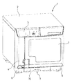
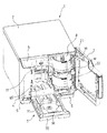
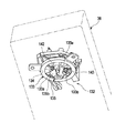
図1は各部を閉状態としたパブリッシャ(メディア処理装置)の外観斜視図、図2は各部を開状態としたパブリッシャの外観斜視図、図3はパブリッシャのケースを外した状態の前方上側から見た斜視図、図4はパブリッシャに設置されたレーベルプリンタ部分の斜視図である。
Hereinafter, an example of a method for controlling a media processing apparatus and an embodiment of the media processing apparatus according to the present invention will be described with reference to the drawings.
In the present embodiment, a disk publisher as a media processing apparatus will be described as an example.
FIG. 1 is an external perspective view of a publisher (media processing apparatus) with each part closed, FIG. 2 is an external perspective view of the publisher with each part open, and FIG. FIG. 4 is a perspective view of a label printer portion installed in the publisher.
図1に示すように、パブリッシャ1は、例えばCDやDVD等の円板状のメディア(情報記録媒体)へのデータの書き込みやメディアのレーベル面への印刷を行うメディア処理装置であり、ほぼ直方体形状のケース2を備えている。このケース2の前面には、左右に開閉可能な開閉扉3,4が取り付けられている。ケース2の上側左端部には、表示ランプ、操作ボタン等が配列された操作面5が設けられており、また、ケース2の下端には、下方に突出するように載置用の脚部6が左右両側に設けられている。左右の脚部6の間位置には引出機構7が設けられている。
As shown in FIG. 1, a publisher 1 is a media processing apparatus that writes data on a disk-shaped medium (information recording medium) such as a CD or DVD and prints on the label side of the medium, and is a substantially rectangular parallelepiped. A
正面視右側の開閉扉3は、図2に示すように、パブリッシャ1の前面側の開口部8を開閉するもので、例えば未使用(ブランク)のメディアMを開口部8を介してセットする時、あるいは作成済みのメディアMを、開口部8を介して取り出すときに、開閉する扉である。
また、正面視左側の開閉扉4は、図3に示すレーベルプリンタ11のインクカートリッジ12の入れ換え時に開閉するためのものであり、この開閉扉4を開けると、鉛直方向に配列された複数のカートリッジホルダ13を有するカートリッジ装着部14が露出するようになっている。
As shown in FIG. 2, the opening / closing door 3 on the right side of the front view opens and closes the opening 8 on the front side of the publisher 1. For example, when setting an unused (blank) medium M through the opening 8. Alternatively, it is a door that opens and closes when the created medium M is taken out through the opening 8.
The opening / closing door 4 on the left side when viewed from the front is for opening and closing when the
図2及び図3に示すように、パブリッシャ1のケース2の内部には、データ書き込み処理が行われていない複数枚(例えば50枚)の未使用のメディアMをスタック可能なメディア保管部としてのメディアスタッカ21と、複数枚(例えば50枚)の未使用のメディアMあるいは作成済みメディアMが保管されるメディア保管部としてのメディアスタッカ22とが保管されるメディアMの中心軸線が同一となるように上下に配置されている。メディアスタッカ21及びメディアスタッカ22は、それぞれ所定位置に対して着脱自在である。
As shown in FIG. 2 and FIG. 3, inside the
上側のメディアスタッカ21は、左右一対の円弧状の枠板24,25を備えており、これにより、メディアMを上側から受け入れ、同軸に積層した状態で収容可能な構成をなしている。メディアスタッカ21にメディアMを収容あるいは補充する作業は、開閉扉3を開けてメディアスタッカ21を取り出すことにより、簡単に行うことが可能となっている。
The
下側のメディアスタッカ22も同一構造となっており、左右一対の円弧状の枠板27,28を備え、これによって、メディアMを上側から受け入れ、同軸に積層した状態で収容可能なスタッカが構成されている。
The
図3に示すように、メディアスタッカ21及びメディアスタッカ22の後側には、メディア搬送機構31が配置されている。メディア搬送機構31は、本体フレーム30とシャーシ32の天板33との間に垂直に架け渡されている垂直ガイド軸35を有している。この垂直ガイド軸35に搬送アーム36が昇降及び旋回可能な状態で支持されている。搬送アーム36は、駆動モータ37によって垂直ガイド軸35に沿って昇降可能であるとともに、垂直ガイド軸35を中心に左右に旋回可能である。
As shown in FIG. 3, a
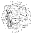
上下のスタッカ21,22及びメディア搬送機構31の側方の後方の部位には、上下に積層された2つのメディアドライブ41が配置され、これらメディアドライブ41の下側にレーベルプリンタ11の後述するキャリッジ62が移動可能に配置されている。
メディアドライブ41は、メディアMへのデータ書き込み位置とメディアMの受け取り受け渡しを行うメディア受け渡し位置との間を移動可能なメディアトレイ41aをそれぞれ有している。
Two media drives 41 stacked one above the other are disposed in the rear side of the upper and
The media drive 41 has
また、レーベルプリンタ11は、メディアMのレーベル面へのレーベル印刷可能な印刷位置とメディアMの受け取り受け渡しを行うメディア受け渡し位置との間を移動可能なメディアトレイ45を有している。
Further, the
図3では、上下のメディアドライブ41のメディアトレイ41aが手前に引き出されてメディア受け渡し位置にある状態及び下側のレーベルプリンタ11のメディアトレイ45が手前側のメディア受け渡し位置にある状態が示されている。また、レーベルプリンタ11はインクジェットプリンタであり、インク供給機構60として各色(本実施形態ではブラック、シアン、マゼンタ、イエロー、ライトシアン、ライトマゼンタの6色)のインクカートリッジ12が用いられ、これらのインクカートリッジ12がカートリッジ装着部14の各カートリッジホルダ13に前方から装着されている。
FIG. 3 shows a state in which the
ここで、メディアスタッカ21の左右一対の枠板24,25の間及びメディアスタッカ22の左右一対の枠板27,28の間には、メディア搬送機構31の搬送アーム36が昇降可能な隙間が形成されている。また、これら上下のメディアスタッカ21とメディアスタッカ22との間には、メディア搬送機構31の搬送アーム36が水平に旋回して、メディアスタッカ22の真上に位置できるように隙間が開いている。さらに、両メディアトレイ41aをメディアドライブ41に押し込むと、メディア搬送機構31の搬送アーム36を下降させて、メディア受け渡し位置にあるメディアトレイ45にアクセス可能となっている。
Here, a gap is formed between the pair of left and
メディア搬送機構31の搬送アーム36は、両メディアトレイ41aをデータ書き込み位置に位置させ、メディアトレイ45を奥側の印刷位置に位置させた状態で、メディアトレイ45の高さ位置よりもさらに下側まで下降可能となっている。そして、メディアトレイ45のメディア受け渡し位置の下方には、搬送アーム36がこの位置まで下降してリリースしたメディアMが通過するガイド穴であって、後述するメディアスタッカ(別体スタッカ)が装着されるガイド穴65が形成されている。
The
図2及び図3に示すように、引出機構7は、本体フレーム30の下側に、本体フレーム30から引き出して開いたり、収納して閉じたりすることが可能な引出トレイ70を有している。引出トレイ70には、スタッカ部71が下方に凹んで設けられている。引出トレイ70が収納位置(閉位置)にあるとき、スタッカ部71は、ガイド穴65の下方に位置し、スタッカ部71の中心部は、受け渡し位置にある両メディアトレイ41aとメディアトレイ45の中心軸線が同一となるように位置されている。このスタッカ部71は、ガイド穴65を介して投入されるメディアMを受け入れ、このメディアMを比較的少量(例えば5枚〜10枚程度)だけ収容する。スタッカ部71は、メディアMを上側から受け入れ、同軸に積層した状態で収容可能となっている。
As shown in FIGS. 2 and 3, the
収納状態にある引出トレイ70のスタッカ部71及びガイド穴65には、スタッカ部71よりもメディアMの収容量が多いメディアスタッカ(別体スタッカ)72が着脱可能となっている(図3参照)。このメディアスタッカ72も、一対の円弧状の枠板73,74を備えており、これによって、メディアMを上側から受け入れ、同軸に積層した状態で複数枚(例えば50枚)収容可能となっている。一対の円弧状の枠板73,74の間には、メディア搬送機構31の搬送アーム36が昇降可能な隙間が形成されている。また、一方の枠板74の上部には着脱時にユーザによって把持される取っ手75が設けられている。
A media stacker (separate stacker) 72 having a larger amount of media M than the
そして、メディアスタッカ72を取り付けた状態とすれば、下側のメディアスタッカ22から未使用のメディアMを取り出し、メディアドライブ41およびレーベルプリンタ11でデータ記録および印刷を行った後に、メディアスタッカ72に収容することができる。
また、例えば、上側のメディアスタッカ21および下側のメディアスタッカ22にそれぞれの最大収容枚数(50枚+50枚)の未使用のメディアMを装填し、下側のメディアスタッカ22の全枚数(50枚)のメディアMを順次処理してメディアスタッカ72に収容し、次に、上側のメディアスタッカ21の全枚数(50枚)のメディアMを順次処理して、空となった下側のメディアスタッカ22に収容する。このようにして、上側のメディアスタッカ21および下側のメディアスタッカ22の最大収容枚数(50枚+50枚)のメディアMを一度に処理する(バッチ処理モード)。
If the
Also, for example, the
また、メディアスタッカ72を取り外した状態とすれば、上側のメディアスタッカ21あるいは下側のメディアスタッカ22から未使用のメディアMを取り出し、メディアドライブ41及びレーベルプリンタ11でデータ記録及び印刷を行った後に、収納状態にある引出トレイ70のスタッカ部71に収容することができる。
Further, if the
これにより、その後、引出トレイ70を引き出すことでスタッカ部71から処理が完了したメディアMを取り出すことができる。つまり、メディアMへの処理中であっても、開閉扉3を閉じたまま、処理が完了したメディアMから順に1枚ずつあるいは複数枚ずつ取り出すことができる(外部排出モード)。
As a result, the completed medium M can be taken out of the
ここで、メディア搬送機構31の搬送アーム36の昇降及び左右への旋回の組み合わせ動作によって、メディアMは、メディアスタッカ21、メディアスタッカ22、引出トレイ70のスタッカ部71(またはメディアスタッカ72)、各メディアドライブ41のメディアトレイ41a及びレーベルプリンタ11のメディアトレイ45間で適宜搬送される。
Here, by the combined operation of raising and lowering the
図4に示すように、レーベルプリンタ11はインク吐出用のノズル(図示省略)を備えたインクジェットヘッド61を有するキャリッジ62を備えており、このキャリッジ62は、キャリッジモータの駆動力でキャリッジガイド軸に沿って水平方向に往復移動する(図示省略)。
As shown in FIG. 4, the
レーベルプリンタ11は、インクカートリッジ12が装着されるカートリッジ装着部14を有するインク供給機構60を備えている。このインク供給機構60は、縦型構造を有しており、パブリッシャ1の本体フレーム30上に立設されて鉛直方向に配設されている。このインク供給機構60には、可撓性を有するインク供給チューブ63の一端が接続されており、このインク供給チューブ63の他端は、キャリッジ62に接続されている。
The
そして、インク供給機構60に装着されるインクカートリッジ12のインクは、インク供給チューブ63を介してキャリッジ62に供給され、このキャリッジ62に設けられたダンパユニット及び背圧調整ユニット(図示省略)を経てインクジェットヘッド61に供給されインクノズル(図示省略)から吐出される。
なお、インク供給機構60には、その上部に主部を配置するように加圧機構64が設けられており、この加圧機構64は、圧縮空気を送り出してインクカートリッジ12内を加圧し、インクカートリッジ12内のインクパックに貯留しているインクを送り出す。
The ink in the
The
また、キャリッジ62のホームポジション(図4に示す位置)における下方側には、ヘッドメンテナンス機構81が設けられている。
このヘッドメンテナンス機構81は、ホームポジションに配置されたキャリッジ62の下面に露出するインクジェットヘッド61のインクノズルを覆うヘッドキャップ82と、インクジェットヘッド61のヘッドクリーニング動作やインク充填動作によってヘッドキャップ82に排出されたインクを吸引する廃インク吸引ポンプ83とを備えている。
A
The
そして、このヘッドメンテナンス機構81の廃インク吸引ポンプ83によって吸引されたインクは、チューブ84を介して、廃インク吸収タンク85へ送り込まれる。
この廃インク吸収タンク85は、ケース86内に図示しない吸収材を配設したもので、その上面は、複数の通気孔87を有するカバー88によって覆われている。
なお、ヘッドメンテナンス機構81の下方には、廃インク吸収タンク85の一部である廃インク受け部89が設けられ、ヘッドメンテナンス機構81から滴下したインクを受け止め、吸収材によって吸収するようになっている。
The ink sucked by the waste
The waste
Below the
(メディア搬送機構)
図5はメディア搬送機構を示す斜視図、図6はメディア搬送機構の一部の斜視図である。
図5に示すように、メディア搬送機構31は、垂直に取り付けられているシャーシ32を備え、ベース72に取り付けられている水平支持板部34とシャーシ32の天板33との間に、垂直ガイド軸35が取り付けられている。そして、この垂直ガイド軸35に搬送アーム36が昇降可能かつ旋回可能な状態で支持されている。
(Media transport mechanism)
FIG. 5 is a perspective view showing the media transport mechanism, and FIG. 6 is a perspective view of a part of the media transport mechanism.
As shown in FIG. 5, the
図6に示すように、搬送アーム36の昇降機構は、駆動源である昇降用の駆動モータ37を備えており、この駆動モータ37の回転が、この駆動モータ37の出力軸に取り付けたピニオン97及び伝達歯車98を介して駆動側プーリ101に伝達されるようになっている。駆動側プーリ101は、シャーシ32の上端近傍位置において、水平な回転軸を中心として回転自在に支持されている。シャーシ32の下端近傍位置には、同じく水平な回転軸を中心として回転自在で従動側プーリ103が支持されており、これら駆動側プーリ101及び従動側プーリ103の間にタイミングベルト104が架け渡されている。このタイミングベルト104の左右のベルト部分の一方には、搬送アーム36の基部が連結されている。
したがって、駆動モータ37を駆動すると、タイミングベルト104が上下方向に移動し、そこに取り付けられている搬送アーム36が垂直ガイド軸35に沿って昇降する。
As shown in FIG. 6, the lifting mechanism of the
Therefore, when the
図5に示すように、搬送アーム36の旋回機構は、駆動源である旋回用の駆動モータ105を備えており、この駆動モータ105の出力軸にはピニオン(図示省略)が取り付けられており、このピニオンの回転が、伝達歯車107を備えた減速歯車列を介して、扇形の最終段歯車109に伝達されるようになっている。扇形の最終段歯車109は、垂直ガイド軸35を中心として左右に旋回可能である。また、この最終段歯車109には、搬送アーム36の昇降機構の構成部品が組み付けられているシャーシ32が搭載されている。駆動モータ105を駆動すると、扇形の最終段歯車109が左右に旋回するので、ここに搭載されているシャーシ32が一体となって垂直ガイド軸35を中心として左右に旋回する。この結果、シャーシ32に搭載されている昇降機構によって保持されている搬送アーム36が垂直ガイド軸35を中心として左右に旋回する。
As shown in FIG. 5, the turning mechanism of the
(搬送アーム)
次に、搬送アーム36について説明する。
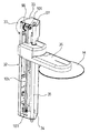
図7は搬送アームの下方側から視た斜視図、図8は搬送アームの裏面図、図9は搬送アームの概略平面図である。
(Transfer arm)
Next, the
7 is a perspective view of the transfer arm as viewed from below, FIG. 8 is a rear view of the transfer arm, and FIG. 9 is a schematic plan view of the transfer arm.
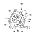
図7及び図8に示すように、搬送アーム36の先端近傍における下面部分は、メディアMを把持する把持部132であって、この把持部132には、メディアガイド133が設けられている。
As shown in FIGS. 7 and 8, the lower surface portion in the vicinity of the tip of the
メディアガイド133は、その中心が、メディアMのピックアップ中心と一致されたもので、アームベース125aの下面側に固定される固定板部134の中心に、下方へ突出するガイド部135を有している。このガイド部135は、メディアMの中心孔Maよりも僅かに小径に形成された円筒状の基端部135aと、この基端部135aから下方へ向かって次第に窄まる円錐形状に形成されたガイド面部135bとを有している。そして、このメディアガイド133は、メディアMに対して近接することにより、メディアMの中心孔Maに挿入され、メディアMの中心孔Maの内周面Mbがガイド面部135bに接触すると、メディアMの中心位置がガイド面部135bによってメディアガイド133の中心位置に調心され、メディアMの中心孔Maが基端部135aに案内されて、メディアMの中心孔Maに基端部135aが挿通される。
The media guide 133 has its center aligned with the pickup center of the media M, and has a
このメディアガイド133には、3つの窓部133aが形成されており、これら窓部133a内の空間で、3本の把持爪(保持部)141〜143が出没可能である。
これら3本の把持爪141〜143は、メディアガイド133によって基端部135aに案内されたメディアMの中心孔Maに挿入し、半径方向外方に押し広がり、メディアガイド133の窓部133aから突出することにより、メディアMの中心孔Maの内周面Mbに当接してメディアMを把持する。
The media guide 133 is formed with three
These three
また、図9に示すように、搬送アーム36は、把持するメディアMの中心孔Maの近傍箇所と対向する位置に設けられた範囲識別センサ(識別センサ)151と、把持するメディアMのレーベル面側のインク受容層からなる印刷可能領域Mcと対向する位置に設けられた種別識別センサ(識別センサ)152とを有している。
これら範囲識別センサ151及び種別識別センサ152は、いずれも把持するメディアMへ照射した光の反射光を検出する光反射型センサである。
Further, as shown in FIG. 9, the
Each of the
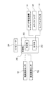
図10に示すように、パブリッシャ1の制御部200には、コンピュータ201が接続され、このコンピュータ201から印刷指令を含む処理指令が制御部200に送信される。また、制御部200の判定部202には、範囲識別センサ151及び種別識別センサ152が接続されており、これら範囲識別センサ151及び種別識別センサ152からの検出信号が送信されるようになっている。
制御部200は、指令部203を有しており、この指令部203から、メディア搬送機構31、メディアドライブ41及びレーベルプリンタ11に駆動指令が送信される。
As shown in FIG. 10, a
The
次に、制御部200によるメディアMの処理の制御について説明する。
図11は印刷処理の制御の流れを示すフローチャートである。
Next, control of media M processing by the
FIG. 11 is a flowchart showing the flow of control of the printing process.
コンピュータ201からメディアMに対する処理指令が送信されると、メディア搬送機構31の搬送アーム36が駆動され、搬送アーム36が、例えば、メディアスタッカ21に収容されている未使用のメディアMの受け取り動作を開始する(ステップS01)。
搬送アーム36がメディアスタッカ21に収容されている最上部のメディアMの受け取り位置に移動すると、範囲識別センサ151及び種別識別センサ152からの検出信号が送信され、まず、範囲識別センサ151の検出信号に基づく判定部202による範囲整合性判定処理が行われる(ステップS02)。
When a processing command for the medium M is transmitted from the
When the
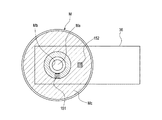
ここで、メディアMには、図12(a)に示すように、中心孔Maから印刷可能領域Mcまでの範囲が大きい標準タイプと、図12(b)に示すように、中心孔Maから印刷可能領域Mcまでの範囲が小さいピクチャタイプとがある。したがって、標準タイプとピクチャタイプとでは、範囲識別センサ151の配設位置での光の反射率が大きく異なることとなる。
Here, on the medium M, as shown in FIG. 12A, a standard type having a large range from the center hole Ma to the printable area Mc and from the center hole Ma as shown in FIG. There is a picture type with a small range up to the possible area Mc. Therefore, the reflectance of light at the position where the
このことより、判定部202では、範囲識別センサ151からの検出信号に基づいて、搬送アーム36が把持しようとしているメディアMのレーベル面に設けられた印刷可能領域Mcの範囲を識別し、その把持対象のメディアMの印刷可能領域Mcの範囲と、コンピュータ201からの処理指令に含まれる印刷指令で指定された印刷領域の範囲とが整合しているか否かを判定する。
Accordingly, the
この範囲整合性判定処理にて、把持対象のメディアMの印刷可能領域Mcの範囲と、印刷指令で指定されたメディアMへの印刷領域の範囲とが整合していると判定されると(ステップS02:Yes)、種別識別センサ152の検出信号に基づく判定部202による種別整合性判定処理が行われる(ステップS03)。
In this range consistency determination processing, if it is determined that the range of the printable area Mc of the medium M to be grasped matches the range of the print area to the medium M specified by the print command (step (S02: Yes), the type consistency determination process by the
ここで、メディアMのインク受容層からなる印刷可能領域Mcには、大別すると、例えば、光沢のないマットタイプあるいは光沢を有する光沢タイプの種別がある。したがって、マットタイプと光沢タイプとでは、印刷可能領域Mcでの光の反射率が大きく異なることとなる。 Here, the printable area Mc composed of the ink receiving layer of the medium M is roughly classified into, for example, a matte type having no gloss or a gloss type having gloss. Therefore, the light reflectance in the printable area Mc differs greatly between the mat type and the gloss type.
このことより、判定部202では、種別識別センサ152からの検出信号に基づいて、搬送アーム36が把持しようとしているメディアMの印刷可能領域Mcの種別を識別し、その印刷可能領域Mcの種別と、コンピュータ201からの処理指令に含まれる印刷指令で指定された印刷種別とが整合しているか否かを判定する。
Accordingly, the
この種別整合性判定処理にて、把持対象のメディアMの印刷可能領域Mcの種別と、印刷指令で指定された印刷種別とが整合していると判定されると(ステップS03:Yes)、メディア搬送機構31は、搬送アーム36によって把持対象のメディアMを把持し、メディアドライブ41へメディアMを受け渡す(ステップS04)。
If it is determined in this type consistency determination processing that the type of the printable area Mc of the medium M to be grasped matches the print type specified by the print command (step S03: Yes), the medium The
メディアドライブ41では、コンピュータ201からの処理指令に基づくデータの書き込み指令が指令部203から送信され、メディアMの記録面へのデータの書き込み処理が行われる(ステップS05)。
In the
メディアドライブ41でのデータの書き込み後、メディア搬送機構31の搬送アーム36が、メディアドライブ41からデータ書き込み処理後のメディアMを受け取り(ステップS06)、レーベルプリンタ11へデータ書き込み処理後のメディアMを受け渡す(ステップS07)。
After the data is written in the
レーベルプリンタ11では、コンピュータ201からの処理指令に基づく印刷指令が指令部203から送信され、メディアMのレーベル面の印刷可能領域Mcへの印刷処理が行われる(ステップS08)。
In the
レーベルプリンタ11での印刷処理後、メディア搬送機構31の搬送アーム36が、レーベルプリンタ11から印刷処理後のメディアMを受け取り(ステップS09)、例えば、引出トレイ70のスタッカ部71(またはメディアスタッカ72)などの処理済みのメディアMを収容するスタッカへメディアMを受け渡す(ステップS10)。
After the printing process by the
上記の処理制御における範囲整合性判定処理(ステップS02)にて把持対象のメディアMの印刷可能領域Mcの範囲と印刷指令で指定された印刷領域の範囲とが整合していないと判定した場合(ステップS02:No)、あるいは種別整合性判定処理(ステップS03)にて、把持対象のメディアMの印刷可能領域Mcの種別と印刷指令で指定された印刷種別とが整合していないと判定した場合(ステップS03:No)、判定部202は、この不整合の判定の回数が所定回数(例えば、2回目)であるか否かを判定する(ステップS11)。
When it is determined in the range consistency determination process (step S02) in the above process control that the range of the printable area Mc of the gripping target medium M and the range of the print area specified by the print command are not consistent ( Step S02: No), or when it is determined in the type consistency determination process (Step S03) that the type of the printable area Mc of the gripping target medium M and the print type specified by the print command are not consistent. (Step S03: No), the
その結果、不整合の判定が所定回数に達している場合は(ステップS11:Yes)、ユーザに対して、処理指令に対応したタイプの未使用のメディアMの補給を促すエラーメッセージを表示する(ステップS12)。 As a result, if the determination of inconsistency has reached a predetermined number of times (step S11: Yes), an error message is displayed prompting the user to replenish unused media M of the type corresponding to the processing command ( Step S12).
不整合の判定の回数が所定回数に達していない場合は(ステップS11:No)、メディア搬送機構31の搬送アーム36が駆動され、例えば、メディアスタッカ22などの他のメディアスタッカに収容されている未使用のメディアMに対する受け取り動作を開始し(ステップS13)、ステップS02以降の処理を行う。なお、不整合の判定の回数は2回以上であれば、2回に限定されない。
When the number of inconsistency determinations has not reached the predetermined number (step S11: No), the
以上、説明したように、上記実施形態によれば、メディアドライブ41によるデータ書き込み処理前に、処理対象のメディアMのレーベル面のタイプと印刷指令で指定されたメディアMのレーベル面のタイプとの整合性を判定する整合性判定処理(ステップS02,S03)を行うので、レーベル面のタイプが不整合であるにも関わらず、データ書き込み処理を行ってしまうことによるメディアMの無駄及び処理時間の浪費をなくすことができる。
これにより、極めて効率良く、処理指令に基づいてデータ書き込み処理及び印刷処理が施されたメディアMを得ることができる。
As described above, according to the above embodiment, before the data writing process by the
Thereby, it is possible to obtain the medium M on which the data writing process and the printing process are performed based on the processing command extremely efficiently.
また、処理対象のメディアMのレーベル面における印刷可能領域Mcの範囲と印刷指令で指定された印刷領域の範囲との整合性を判定することで、レーベル面のタイプの不整合を容易に判定することができる。
さらには、処理対象のメディアMのレーベル面における印刷可能領域Mcの種別と印刷指令で指定された印刷種別との整合性を判定することで、レーベル面のタイプの不整合を容易に判定することができる。
Further, by determining the consistency between the range of the printable area Mc on the label surface of the medium M to be processed and the range of the print area specified by the print command, the label surface type mismatch is easily determined. be able to.
Further, by determining the consistency between the type of the printable area Mc on the label surface of the medium M to be processed and the print type specified by the print command, it is possible to easily determine the mismatch of the label surface type. Can do.
また、整合性判定処理(ステップS02,S03)にてメディアMのレーベル面のタイプが不整合と判定した際に、不整合と判定したメディアMの収容箇所以外に収容されているメディアMに対して改めて整合性判定処理(ステップS02,S03)を行うことで、このメディアMのレーベル面のタイプが整合していれば、そのメディアMに対してデータ書き込み処理及び印刷処理を行うことができる。これにより、処理指令に基づいてデータ書き込み処理及び印刷処理が施されたメディアMを効率良く得ることができる。 Further, when it is determined in the consistency determination process (steps S02 and S03) that the type of the label surface of the medium M is inconsistent, the medium M accommodated in a location other than the accommodation location of the medium M determined to be inconsistent. By performing the consistency determination processing (steps S02 and S03) again, if the type of the label surface of the medium M is consistent, the data writing process and the printing process can be performed on the medium M. Thereby, it is possible to efficiently obtain the medium M on which the data writing process and the printing process are performed based on the processing command.
なお、前述の制御におけるステップS11にて不整合の判定の回数が所定回数(例えば、2回目)に達していない場合に(ステップS11:No)、例えば、メディアスタッカ22などの他のメディアスタッカのメディアMに対する受け取り動作を行うようにしたが(ステップS13)、メディア搬送機構31の搬送アーム36を駆動させて不整合と判定したメディアスタッカ21の最上部のメディアMを他のメディアスタッカへ移動させ、再び同一のメディアスタッカ21に収容されているメディアMに対する受け取り動作を開始し、ステップS02以降の処理を行うようにしても良い。
When the number of inconsistency determinations does not reach a predetermined number (for example, the second time) in step S11 in the above-described control (step S11: No), for example, other media stackers such as the
このようにすれば、整合性判定処理(ステップS02,S03)にてメディアMのレーベル面のタイプが不整合と判定した際に、不整合と判定したメディアMの下方に積層されているメディアMに対して改めて整合性判定処理(ステップS02,S03)を行うことで、このメディアMのレーベル面のタイプが整合していれば、そのメディアMに対してデータ書き込み処理及び印刷処理を行うことができる。これにより、処理指令に基づいてデータ書き込み処理及び印刷処理が施されたメディアを効率良く得ることができる。 In this way, when the label type of the medium M is determined to be inconsistent in the consistency determination processing (steps S02 and S03), the medium M stacked below the medium M determined to be inconsistent. If the label surface type of the medium M is matched by performing the consistency determination process (steps S02 and S03) again, the data writing process and the printing process can be performed on the medium M. it can. Thereby, it is possible to efficiently obtain a medium on which data writing processing and printing processing are performed based on the processing command.
なお、上記実施形態では、範囲識別センサ151及び種別識別センサ152を搬送アーム36に搭載させたが、例えば、メディアスタッカ21,22の上方に範囲識別センサ151及び種別識別センサ152を取り付け、これら範囲識別センサ151及び種別識別センサ152からの検出信号に基づいて判定部202にて整合性判定処理(ステップS02,S03)を行わせても良い。
In the above embodiment, the
また、上記実施形態では、搬送アーム36に、範囲識別センサ151及び種別識別センサ152の二つの識別センサを設けたが、範囲識別センサ151だけを設け、種別識別センサ152の機能を範囲識別センサ151に持たせても良い。
In the above embodiment, the
この場合、種別整合性判定処理(ステップS03)を行う際に、搬送アーム36を回動させて標準タイプ及びピクチャタイプのいずれのメディアMにおいても印刷可能領域Mcが存在する位置へ範囲識別センサ151を配置させる。これにより、この範囲識別センサ151からの検出信号に基づいて、印刷可能領域Mcの種別の判定も行うことができる。
In this case, when the type consistency determination process (step S03) is performed, the
なお、本発明で用いられるメディアは、上記実施形態のメディアMのような円板状のメディアに限定されるものではなく、矩形状等の多角形状や楕円状のメディアにも適用可能であり、また、その記録方式も、光記録方式、光磁気記録方式等、何ら限定されるものではない。 The medium used in the present invention is not limited to a disk-shaped medium such as the medium M in the above embodiment, and can be applied to a polygonal or elliptical medium such as a rectangular shape. Also, the recording method is not limited at all, such as an optical recording method and a magneto-optical recording method.
1…パブリッシャ(メディア処理装置)、11…レーベルプリンタ(印刷処理部)、21,22…メディアスタッカ(収容部)、31…メディア搬送機構(搬送部)、36…搬送アーム(搬送部)、41…メディアドライブ(データ処理部)、151…範囲識別センサ(識別センサ)、152…種別識別センサ(識別センサ)、202…判定部、Mc…印刷可能領域、M…メディア。 DESCRIPTION OF SYMBOLS 1 ... Publisher (media processing apparatus), 11 ... Label printer (printing process part), 21, 22 ... Media stacker (accommodating part), 31 ... Media conveyance mechanism (conveyance part), 36 ... Conveyance arm (conveyance part), 41 ... Media drive (data processing unit), 151 ... Range identification sensor (identification sensor), 152 ... Type identification sensor (identification sensor), 202 ... Determining part, Mc ... Printable area, M ... Media.
Claims (8)
前記データ書き込み処理前に、処理対象のメディアのレーベル面のタイプと前記処理指令における印刷指令で指定されたメディアのレーベル面のタイプとの整合性を判定する整合性判定処理を行うことを特徴とするメディア処理装置の制御方法。 A control method of a media processing apparatus that performs data writing processing on a recording surface of a medium based on a processing command and then performs printing processing on the label surface of the media,
Before the data writing process, a consistency determination process is performed to determine consistency between the type of the label surface of the medium to be processed and the type of the label surface of the medium specified by the print command in the processing command. Method for controlling a media processing apparatus.
前記整合性判定処理では、処理対象のメディアのレーベル面における印刷可能領域の範囲と前記印刷指令で指定された印刷領域の範囲との整合性を判定することを特徴とするメディア処理装置の制御方法。 A control method for a media processing device according to claim 1,
In the consistency determination process, the consistency of the printable area range on the label surface of the medium to be processed and the print area range specified by the print command is determined. .
前記整合性判定処理では、処理対象のメディアのレーベル面における印刷可能領域の種別と前記印刷指令で指定された印刷種別との整合性を判定することを特徴とするメディア処理装置の制御方法。 A method for controlling a media processing device according to claim 1 or 2,
The method for controlling a media processing apparatus, wherein the consistency determination processing determines consistency between a type of a printable area on a label surface of a medium to be processed and a print type designated by the print command.
前記整合性判定処理にてメディアのレーベル面のタイプが不整合と判定した際に、不整合と判定したメディアの収容箇所以外に収容されているメディアに対して前記整合性判定処理を行うことを特徴とするメディア処理装置の制御方法。 A method for controlling a media processing device according to any one of claims 1 to 3,
When it is determined that the type of the label surface of the medium is inconsistent in the consistency determination process, the consistency determination process is performed on a medium stored in a place other than the storage position of the medium determined to be inconsistent. A method for controlling a media processing apparatus.
前記整合性判定処理にてメディアのレーベル面のタイプが不整合と判定した際に、不整合と判定したメディアの下方に積層されているメディアに対して前記整合性判定処理を行うことを特徴とするメディア処理装置の制御方法。 A method for controlling a media processing device according to any one of claims 1 to 3,
When it is determined that the label surface type of the media is inconsistent in the consistency determination processing, the consistency determination processing is performed on the media stacked below the media determined to be inconsistent. Method for controlling a media processing apparatus.
前記搬送部に設けられて前記メディアのレーベル面のタイプを識別する識別センサと、
前記識別センサからの検出信号に基づき、処理対象のメディアのレーベル面のタイプと前記処理指令における印刷指令で指定されたメディアのレーベル面のタイプとの整合性を判定する判定部とを備えたことを特徴とするメディア処理装置。 Based on the processing command, a data processing unit that performs data writing processing on the recording surface of the media, a printing processing unit that performs printing processing on the label surface of the media, a storage unit that stores the media, and transports the media A media processing device comprising a transport unit for
An identification sensor provided in the transport unit for identifying the type of the label surface of the media;
Based on a detection signal from the identification sensor, a determination unit is provided that determines the consistency between the type of the label surface of the medium to be processed and the type of the label surface of the medium specified by the print command in the processing command. A media processing device characterized by the above.
前記判定部は、前記識別センサからの検出信号に基づき、処理対象のメディアのレーベル面における印刷可能領域の範囲と前記印刷指令で指定された印刷領域の範囲との整合性を判定することを特徴とするメディア処理装置。 The media processing device according to claim 6,
The determination unit determines consistency between a printable area range on a label surface of a medium to be processed and a print area range specified by the print command based on a detection signal from the identification sensor. A media processing device.
前記判定部は、前記識別センサからの検出信号に基づき、処理対象のメディアのレーベル面における印刷可能領域の種別と前記印刷指令で指定された印刷種別との整合性を判定することを特徴とするメディア処理装置。 The media processing device according to claim 6 or 7, wherein:
The determination unit determines consistency between a printable area type on a label surface of a medium to be processed and a print type specified by the print command based on a detection signal from the identification sensor. Media processing device.
Priority Applications (1)
| Application Number | Priority Date | Filing Date | Title |
|---|---|---|---|
| JP2008320061A JP2010146611A (en) | 2008-12-16 | 2008-12-16 | Method of controlling media processor and the media processor |
Applications Claiming Priority (1)
| Application Number | Priority Date | Filing Date | Title |
|---|---|---|---|
| JP2008320061A JP2010146611A (en) | 2008-12-16 | 2008-12-16 | Method of controlling media processor and the media processor |
Publications (1)
| Publication Number | Publication Date |
|---|---|
| JP2010146611A true JP2010146611A (en) | 2010-07-01 |
Family
ID=42566894
Family Applications (1)
| Application Number | Title | Priority Date | Filing Date |
|---|---|---|---|
| JP2008320061A Pending JP2010146611A (en) | 2008-12-16 | 2008-12-16 | Method of controlling media processor and the media processor |
Country Status (1)
| Country | Link |
|---|---|
| JP (1) | JP2010146611A (en) |
-
2008
- 2008-12-16 JP JP2008320061A patent/JP2010146611A/en active Pending
Similar Documents
| Publication | Publication Date | Title |
|---|---|---|
| JP4918888B2 (en) | Media processing apparatus and control method thereof | |
| JP4877091B2 (en) | Control method of media transport mechanism and media processing apparatus | |
| JP2010253932A (en) | Label printer, media processing device, and media processing system | |
| JP5136073B2 (en) | Media transport mechanism and media processing apparatus provided with the same | |
| JP2009181636A (en) | Medium processor | |
| EP2006852B1 (en) | Media processing apparatus and controlling method of the same | |
| JP2008135148A (en) | Media processor | |
| JP2008108309A (en) | Media processor | |
| JP4835369B2 (en) | Media transport mechanism and media processing apparatus provided with the same | |
| JP2010146611A (en) | Method of controlling media processor and the media processor | |
| JP4946654B2 (en) | Media processing apparatus and control method thereof | |
| JP5193528B2 (en) | Media processing apparatus and method for controlling media processing apparatus | |
| JP4962238B2 (en) | Information processing apparatus control method and information processing apparatus | |
| JP5071128B2 (en) | Media processing device | |
| JP2009023133A (en) | Printing device control method, and printing device | |
| JP4930210B2 (en) | Media processing device | |
| JP4918887B2 (en) | Media processing device | |
| JP2009163822A (en) | Media processing device | |
| JP5228874B2 (en) | Media transport mechanism and media processing apparatus | |
| JP4930221B2 (en) | Control method of media transport mechanism and media processing apparatus | |
| JP2009176376A (en) | Medium conveying mechanism and medium processing device equipped with the same | |
| JP5061840B2 (en) | Media processing device | |
| JP2008108307A (en) | Media processing apparatus and its control method | |
| JP2009196290A (en) | Method for controlling printer, printer, and medium processing apparatus | |
| JP2009176377A (en) | Medium processor |