JP2010146600A - Perpendicular magnetic recording head, method of manufacturing the same, and magnetic recording/reproducing device - Google Patents
Perpendicular magnetic recording head, method of manufacturing the same, and magnetic recording/reproducing device Download PDFInfo
- Publication number
- JP2010146600A JP2010146600A JP2008319571A JP2008319571A JP2010146600A JP 2010146600 A JP2010146600 A JP 2010146600A JP 2008319571 A JP2008319571 A JP 2008319571A JP 2008319571 A JP2008319571 A JP 2008319571A JP 2010146600 A JP2010146600 A JP 2010146600A
- Authority
- JP
- Japan
- Prior art keywords
- magnetic
- main
- pole
- film
- layer
- Prior art date
- Legal status (The legal status is an assumption and is not a legal conclusion. Google has not performed a legal analysis and makes no representation as to the accuracy of the status listed.)
- Pending
Links
- 238000004519 manufacturing process Methods 0.000 title claims description 37
- 238000000034 method Methods 0.000 claims description 64
- NJPPVKZQTLUDBO-UHFFFAOYSA-N novaluron Chemical compound C1=C(Cl)C(OC(F)(F)C(OC(F)(F)F)F)=CC=C1NC(=O)NC(=O)C1=C(F)C=CC=C1F NJPPVKZQTLUDBO-UHFFFAOYSA-N 0.000 claims description 53
- 230000004907 flux Effects 0.000 claims description 35
- 238000007747 plating Methods 0.000 claims description 32
- 238000005530 etching Methods 0.000 claims description 18
- 239000011347 resin Substances 0.000 claims description 16
- 229920005989 resin Polymers 0.000 claims description 16
- 238000010030 laminating Methods 0.000 claims description 13
- 230000001681 protective effect Effects 0.000 claims description 13
- 239000000758 substrate Substances 0.000 claims description 12
- 239000000956 alloy Substances 0.000 claims description 5
- 229910045601 alloy Inorganic materials 0.000 claims description 5
- 239000000126 substance Substances 0.000 claims description 3
- 229910003321 CoFe Inorganic materials 0.000 claims 1
- 229910001030 Iron–nickel alloy Inorganic materials 0.000 claims 1
- 230000015572 biosynthetic process Effects 0.000 claims 1
- 238000003475 lamination Methods 0.000 claims 1
- 238000009826 distribution Methods 0.000 abstract description 10
- 239000010408 film Substances 0.000 description 124
- 239000010410 layer Substances 0.000 description 117
- 239000007789 gas Substances 0.000 description 21
- 230000000694 effects Effects 0.000 description 20
- 230000005415 magnetization Effects 0.000 description 20
- 230000008569 process Effects 0.000 description 19
- 238000010586 diagram Methods 0.000 description 16
- 238000000992 sputter etching Methods 0.000 description 14
- 239000002356 single layer Substances 0.000 description 12
- 229910052742 iron Inorganic materials 0.000 description 11
- XEEYBQQBJWHFJM-UHFFFAOYSA-N iron Substances [Fe] XEEYBQQBJWHFJM-UHFFFAOYSA-N 0.000 description 11
- 239000000696 magnetic material Substances 0.000 description 11
- 230000002829 reductive effect Effects 0.000 description 11
- 230000000052 comparative effect Effects 0.000 description 10
- 229910052759 nickel Inorganic materials 0.000 description 9
- PXHVJJICTQNCMI-UHFFFAOYSA-N nickel Substances [Ni] PXHVJJICTQNCMI-UHFFFAOYSA-N 0.000 description 9
- 238000001020 plasma etching Methods 0.000 description 8
- 238000009713 electroplating Methods 0.000 description 7
- 239000000463 material Substances 0.000 description 5
- 238000000926 separation method Methods 0.000 description 5
- YCKRFDGAMUMZLT-UHFFFAOYSA-N Fluorine atom Chemical compound [F] YCKRFDGAMUMZLT-UHFFFAOYSA-N 0.000 description 4
- VNNRSPGTAMTISX-UHFFFAOYSA-N chromium nickel Chemical compound [Cr].[Ni] VNNRSPGTAMTISX-UHFFFAOYSA-N 0.000 description 4
- 230000007423 decrease Effects 0.000 description 4
- 239000011737 fluorine Substances 0.000 description 4
- 229910052731 fluorine Inorganic materials 0.000 description 4
- 229910001120 nichrome Inorganic materials 0.000 description 4
- 230000035699 permeability Effects 0.000 description 4
- 239000000725 suspension Substances 0.000 description 4
- ZAMOUSCENKQFHK-UHFFFAOYSA-N Chlorine atom Chemical compound [Cl] ZAMOUSCENKQFHK-UHFFFAOYSA-N 0.000 description 3
- 229910052801 chlorine Inorganic materials 0.000 description 3
- 239000000460 chlorine Substances 0.000 description 3
- 239000010419 fine particle Substances 0.000 description 3
- 150000004767 nitrides Chemical class 0.000 description 3
- 230000002441 reversible effect Effects 0.000 description 3
- 229910052715 tantalum Inorganic materials 0.000 description 3
- 229910018072 Al 2 O 3 Inorganic materials 0.000 description 2
- 230000002238 attenuated effect Effects 0.000 description 2
- 229910002091 carbon monoxide Inorganic materials 0.000 description 2
- 230000008859 change Effects 0.000 description 2
- 150000003949 imides Chemical class 0.000 description 2
- 239000002184 metal Substances 0.000 description 2
- 229910052751 metal Inorganic materials 0.000 description 2
- 229910052750 molybdenum Inorganic materials 0.000 description 2
- 229910052758 niobium Inorganic materials 0.000 description 2
- 238000005498 polishing Methods 0.000 description 2
- 229910052703 rhodium Inorganic materials 0.000 description 2
- 239000010409 thin film Substances 0.000 description 2
- 238000001039 wet etching Methods 0.000 description 2
- MYMOFIZGZYHOMD-UHFFFAOYSA-N Dioxygen Chemical compound O=O MYMOFIZGZYHOMD-UHFFFAOYSA-N 0.000 description 1
- KGWWEXORQXHJJQ-UHFFFAOYSA-N [Fe].[Co].[Ni] Chemical compound [Fe].[Co].[Ni] KGWWEXORQXHJJQ-UHFFFAOYSA-N 0.000 description 1
- 238000013459 approach Methods 0.000 description 1
- 230000008901 benefit Effects 0.000 description 1
- 230000000740 bleeding effect Effects 0.000 description 1
- 239000002131 composite material Substances 0.000 description 1
- 239000004020 conductor Substances 0.000 description 1
- 230000008878 coupling Effects 0.000 description 1
- 238000010168 coupling process Methods 0.000 description 1
- 238000005859 coupling reaction Methods 0.000 description 1
- 230000003247 decreasing effect Effects 0.000 description 1
- 238000000151 deposition Methods 0.000 description 1
- 230000001687 destabilization Effects 0.000 description 1
- 229910001882 dioxygen Inorganic materials 0.000 description 1
- 229910052737 gold Inorganic materials 0.000 description 1
- 238000009413 insulation Methods 0.000 description 1
- 230000005389 magnetism Effects 0.000 description 1
- 239000012528 membrane Substances 0.000 description 1
- 230000003647 oxidation Effects 0.000 description 1
- 238000007254 oxidation reaction Methods 0.000 description 1
- 230000002093 peripheral effect Effects 0.000 description 1
- 238000004528 spin coating Methods 0.000 description 1
- 238000004544 sputter deposition Methods 0.000 description 1
Images


Classifications
-
- G—PHYSICS
- G11—INFORMATION STORAGE
- G11B—INFORMATION STORAGE BASED ON RELATIVE MOVEMENT BETWEEN RECORD CARRIER AND TRANSDUCER
- G11B5/00—Recording by magnetisation or demagnetisation of a record carrier; Reproducing by magnetic means; Record carriers therefor
- G11B5/127—Structure or manufacture of heads, e.g. inductive
- G11B5/31—Structure or manufacture of heads, e.g. inductive using thin films
- G11B5/3109—Details
- G11B5/3116—Shaping of layers, poles or gaps for improving the form of the electrical signal transduced, e.g. for shielding, contour effect, equalizing, side flux fringing, cross talk reduction between heads or between heads and information tracks
-
- G—PHYSICS
- G11—INFORMATION STORAGE
- G11B—INFORMATION STORAGE BASED ON RELATIVE MOVEMENT BETWEEN RECORD CARRIER AND TRANSDUCER
- G11B5/00—Recording by magnetisation or demagnetisation of a record carrier; Reproducing by magnetic means; Record carriers therefor
- G11B5/127—Structure or manufacture of heads, e.g. inductive
- G11B5/1278—Structure or manufacture of heads, e.g. inductive specially adapted for magnetisations perpendicular to the surface of the record carrier
-
- G—PHYSICS
- G11—INFORMATION STORAGE
- G11B—INFORMATION STORAGE BASED ON RELATIVE MOVEMENT BETWEEN RECORD CARRIER AND TRANSDUCER
- G11B5/00—Recording by magnetisation or demagnetisation of a record carrier; Reproducing by magnetic means; Record carriers therefor
- G11B5/127—Structure or manufacture of heads, e.g. inductive
- G11B5/31—Structure or manufacture of heads, e.g. inductive using thin films
- G11B5/3163—Fabrication methods or processes specially adapted for a particular head structure, e.g. using base layers for electroplating, using functional layers for masking, using energy or particle beams for shaping the structure or modifying the properties of the basic layers
-
- Y—GENERAL TAGGING OF NEW TECHNOLOGICAL DEVELOPMENTS; GENERAL TAGGING OF CROSS-SECTIONAL TECHNOLOGIES SPANNING OVER SEVERAL SECTIONS OF THE IPC; TECHNICAL SUBJECTS COVERED BY FORMER USPC CROSS-REFERENCE ART COLLECTIONS [XRACs] AND DIGESTS
- Y10—TECHNICAL SUBJECTS COVERED BY FORMER USPC
- Y10T—TECHNICAL SUBJECTS COVERED BY FORMER US CLASSIFICATION
- Y10T29/00—Metal working
- Y10T29/49—Method of mechanical manufacture
- Y10T29/49002—Electrical device making
- Y10T29/4902—Electromagnet, transformer or inductor
- Y10T29/49021—Magnetic recording reproducing transducer [e.g., tape head, core, etc.]
- Y10T29/49032—Fabricating head structure or component thereof
- Y10T29/49036—Fabricating head structure or component thereof including measuring or testing
- Y10T29/49043—Depositing magnetic layer or coating
- Y10T29/49044—Plural magnetic deposition layers
Landscapes
- Engineering & Computer Science (AREA)
- Manufacturing & Machinery (AREA)
- Magnetic Heads (AREA)
Abstract
【課題】狭トラック化された記録ヘッドにおいて、高い記録磁界強度と勾配を有し、スキュー時の隣接トラックへの書き込みを抑制する磁気的逃げ角を維持する。
【解決手段】記録媒体に対向する主磁極1aの浮上面より後退したトレーリング側にトラック幅より張り出した磁性膜5を備えることにより、トレーリング側の磁界強度を強くして主磁極に付与された幾何Bevel角で規定された磁界強度分布の差を大きくし、隣接トラックに対して大きな磁気的逃げ角を発生しながら主磁極の書き込み能力を大きくする。
【選択図】図4In a recording head with a narrow track, a magnetic clearance angle is maintained which has a high recording magnetic field strength and a gradient and suppresses writing to an adjacent track during skewing.
A magnetic film projecting from a track width is provided on a trailing side of a main magnetic pole facing a recording medium which is retreated from the air bearing surface, so that the magnetic field strength on the trailing side is increased and applied to the main magnetic pole. The magnetic field strength distribution difference defined by the geometric Bevel angle is increased, and the writing ability of the main pole is increased while generating a large magnetic clearance angle with respect to adjacent tracks.
[Selection] Figure 4
Description
本発明は、磁気記録媒体に対して記録磁界を発生する磁気記録ヘッド、及びその磁気記録ヘッドを搭載した磁気記録再生装置に関する。 The present invention relates to a magnetic recording head that generates a recording magnetic field on a magnetic recording medium, and a magnetic recording / reproducing apparatus equipped with the magnetic recording head.
近年、情報量の増大に伴い磁気記録再生装置においても高い面内記録密度への要望が増しており、磁気記録媒体への記録情報量を上げるために、磁気記録媒体の磁性微粒子を小さくするとともに書き込み磁極の狭小化が求められている。しかし磁性微粒子を小さくすると体積が減少することになり、磁気記録媒体の磁化領域での不安定化の要因としての磁化の熱揺らぎが問題となった。この問題を解決する手法として、記録層の膜厚を厚くして磁性微粒子の体積を増加させながら記録媒体に垂直な方向に磁化信号を記録する垂直磁気記録方式が提案された。垂直磁気記録方式に用いられる磁気記録ヘッドの主磁極は、磁気記録媒体の走行方向に対してトレーリング側の幅が広く、リーディング側の幅が狭い逆台形形状を有し、Bevel角度(主磁極のスロートハイトのトレーリング側の幅とリーディング側の2つの異なる幅からなる傾き角度)により主磁極のトレーリング側の放出する磁束の量とリーディング側の放出する磁束の量に差を設けて、磁気記録媒体側に情報を書き込む際に隣接するトラックの情報データの減衰及び消去を防ぐための磁気的逃げ角を備えている。この垂直磁気記録方式も現状では、面記録密度を上げるために磁気記録媒体に対して垂直な記録用磁界を発生させる書き込み用の単磁極部が狭小化され、磁気記録媒体を磁化反転させる充分な垂直磁界を発生させることが困難になりつつある。 In recent years, as the amount of information increases, there is an increasing demand for high in-plane recording density in magnetic recording / reproducing apparatuses. In order to increase the amount of information recorded on the magnetic recording medium, the magnetic fine particles of the magnetic recording medium are made smaller. There is a demand for narrowing the write magnetic pole. However, when the magnetic fine particles are made smaller, the volume is reduced, and thermal fluctuation of magnetization as a factor of destabilization in the magnetization region of the magnetic recording medium becomes a problem. As a technique for solving this problem, a perpendicular magnetic recording method has been proposed in which the magnetization signal is recorded in a direction perpendicular to the recording medium while increasing the volume of the magnetic fine particles by increasing the thickness of the recording layer. The main magnetic pole of the magnetic recording head used in the perpendicular magnetic recording system has an inverted trapezoidal shape with a wide trailing side and a narrow leading side with respect to the traveling direction of the magnetic recording medium, and a Bevel angle (main magnetic pole). The difference in the amount of magnetic flux emitted on the trailing side of the main magnetic pole and the amount of magnetic flux emitted on the leading side by the width of the trailing side of the throat height and the two different widths on the leading side) A magnetic clearance angle is provided to prevent attenuation and erasure of information data of adjacent tracks when information is written on the magnetic recording medium side. At present, this perpendicular magnetic recording system also has a narrow single magnetic pole portion for writing that generates a recording magnetic field perpendicular to the magnetic recording medium in order to increase the surface recording density, and is sufficient to reverse the magnetization of the magnetic recording medium. It is becoming difficult to generate a vertical magnetic field.
そこで、書き込み用の単磁極部の狭小化による書き込み磁界強度の不足を補うために、主磁極の幅を規定しているスロートハイト部を短くして、磁束の飽和位置をより浮上面側に近づけることで磁界強度を確保する方法が用いられるが、この場合、スロートハイト部に磁束を導く幅の広いフレア部が浮上面に近接することでフレア部から漏れる磁束とスロートハイト部から放出する磁束が合成され、磁気記録ヘッドの浮上面の主磁極形状で規定していた磁気記録媒体への磁化反転領域が広くなって、隣接するトラックに書き込まれた情報の減衰及び消去が発生するために主磁極の放出する磁束からなる磁界強度分布のリーディング側の等磁界線が規定され、隣接トラックに対する磁気的逃げ角に影響をおよぼすことになる。 Therefore, in order to make up for the shortage of the write magnetic field strength due to the narrowing of the single magnetic pole for writing, the throat height defining the width of the main pole is shortened to bring the saturation position of the magnetic flux closer to the air bearing surface. In this case, magnetic flux leaking from the flare portion and magnetic flux released from the throat height portion are caused by the fact that the wide flare portion that guides the magnetic flux to the throat height portion is close to the air bearing surface. Since the magnetization reversal region to the magnetic recording medium, which is synthesized and defined by the main magnetic pole shape of the air bearing surface of the magnetic recording head, is widened, attenuation and erasure of information written in the adjacent track occurs. The leading magnetic field lines of the magnetic field intensity distribution made up of the magnetic flux emitted from the magnetic field are defined, which affects the magnetic clearance angle with respect to the adjacent track.
さらに、磁気ヘッドの搭載されているスライダーを固定しているサスペンションアームが、記録再生を行うために磁気記録媒体の内側から外側まで走査される際に、磁気記録媒体の記録再生トラック位置により磁気ヘッドは異なる角度となる。これがスキュー角である。磁気ヘッドにスキュー角がついた場合、記録ヘッドの主磁極も同等の傾きが付与されるために、磁気ヘッドが磁気記録媒体のどのトラック位置にいても隣接するトラックのデータを減衰及び消去することになり、磁気的逃げ角を確保しながら高い磁界強度を磁気記録媒体の記録層へ放出することが高記録密度化にとって必須である。 Further, when the suspension arm that fixes the slider on which the magnetic head is mounted is scanned from the inside to the outside of the magnetic recording medium for recording and reproduction, the magnetic head is changed depending on the recording / reproducing track position of the magnetic recording medium. Are at different angles. This is the skew angle. When the magnetic head has a skew angle, the main magnetic pole of the recording head is given the same inclination, so that the data of the adjacent track is attenuated and erased regardless of the track position of the magnetic recording medium. Therefore, it is indispensable for increasing the recording density to release a high magnetic field strength to the recording layer of the magnetic recording medium while ensuring a magnetic clearance angle.
そこで、十分な磁気的逃げ角を得るためには主磁極の膜厚を薄くするか、あるいは主磁極のBevel角度を大きくする方法があるが、主磁極の浮上面の磁束を放出する面積が減少して磁界強度が低下することになる。 Therefore, in order to obtain a sufficient magnetic clearance angle, there are methods of reducing the thickness of the main pole or increasing the Bevel angle of the main pole, but the area of the main pole where the magnetic flux is released is reduced. As a result, the magnetic field strength decreases.
この対策として、特開2007−220208号公報,特開2007−220209号公報及び特開2007−242132号公報には、主磁極の形状をT字型にすることにより、幅広い部位で書き込みトラックの幾何学的幅を規定しながら磁界強度を確保して磁気記録媒体側に磁気的逃げ角を確保する方法が記載されている。 As measures against this, Japanese Patent Application Laid-Open Nos. 2007-220208, 2007-220209, and 2007-242132 disclose a T-shaped main pole so that the geometry of a write track can be changed over a wide area. Describes a method of ensuring a magnetic clearance angle on the magnetic recording medium side by securing a magnetic field strength while defining a geometric width.
高い面内記録密度を実現するためには、磁気記録媒体の磁性粒の微小化とともに磁気ヘッドの記録再生トラックの狭小化が必須である。記録ヘッドにおける書き込み用の単磁極の狭小化は、浮上面の主磁極面積を減少し、磁極面積に比例する書き込み磁界強度を低下させる。また、磁気ヘッドにスキュー角がついた場合でも、隣接するトラックに書き込まれた情報の減衰及び消去しないための磁気的逃げ角を確保することも重要な課題となる。 In order to realize a high in-plane recording density, it is indispensable to reduce the size of the magnetic recording medium and to reduce the recording / reproducing track of the magnetic head. The narrowing of the single magnetic pole for writing in the recording head reduces the main magnetic pole area on the air bearing surface and lowers the write magnetic field intensity proportional to the magnetic pole area. In addition, even when the magnetic head has a skew angle, it is an important issue to secure a magnetic clearance angle for preventing attenuation and erasure of information written in adjacent tracks.
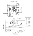
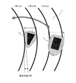
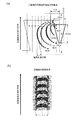
図23は、磁気記録媒体と磁気記録ヘッド位置を示す概念図である。磁気記録媒体11の外周方向にサスペンションアームに固定されたスライダーが移動してスキュー角が付いた場合の磁気記録ヘッドの主磁極を想定すると、トラックC上のBevel角の無い矩形の主磁極1aの場合は、磁気記録媒体の記録層を磁化反転させる磁界強度分布は書き込み磁極の側面に沿った広がりを示し、主磁極のリーディング側から離れるにつれて、幅の狭まる磁界強度分布を示す。したがって、リーディング側の書き込み磁界は、隣接するトラックBの一部に印加され、トラックBに書き込まれた情報が減衰及び消去されてしまう。
FIG. 23 is a conceptual diagram showing the magnetic recording medium and the position of the magnetic recording head. Assuming the main magnetic pole of the magnetic recording head when the slider fixed to the suspension arm moves in the outer peripheral direction of the
しかし、トラックA上のBevel角の付与による逆台形形状を有する主磁極1aの場合は、磁界強度分布は書き込み磁極に沿った広がりを示すが、Bevel角が隣接するトラックに対して磁気的逃げ角(主磁極の記録磁界強度が記録媒体の保磁力と等しくなる等高線のトラック方向の最も幅広い点からリーディング側方向の等高線の角度)を発生させるために隣接トラックに影響を与えること無く記録することができる。このことから、主磁極のBevel角の役割は大きいことが分かる。しかしながら、高記録密度になるにしたがってトラック幅は狭小化されることから、Bevel角は形成しにくくなる問題が生じる。また、主磁極の狭小化により浮上面の主磁極面積が小さくなり、書き込み磁界強度の低下を生じる問題がある。 However, in the case of the main magnetic pole 1a having an inverted trapezoidal shape by giving a Bevel angle on the track A, the magnetic field strength distribution shows an extension along the write magnetic pole, but the Bevel angle is a magnetic clearance angle with respect to the adjacent track. In order to generate (the angle of the contour line in the leading side direction from the widest point in the track direction of the contour line where the recording magnetic field strength of the main magnetic pole becomes equal to the coercive force of the recording medium), recording can be performed without affecting the adjacent tracks. it can. From this, it can be seen that the role of the Bevel angle of the main pole is large. However, since the track width becomes narrower as the recording density becomes higher, there arises a problem that it becomes difficult to form the Bevel angle. Further, there is a problem that the main magnetic pole area on the air bearing surface is reduced due to the narrowing of the main magnetic pole, and the write magnetic field strength is reduced.
本発明の目的は、記録ヘッドの主磁極が狭小化されても充分な磁界強度を確保し、かつ磁気ヘッドにスキュー角がついた場合でも隣接トラックに対する磁気的逃げ角を確保し、高記録密度を実現する垂直磁気記録ヘッドを提供することにある。 The object of the present invention is to ensure a sufficient magnetic field strength even when the main pole of the recording head is narrowed, and to ensure a magnetic clearance angle with respect to adjacent tracks even when the magnetic head has a skew angle. Is to provide a perpendicular magnetic recording head.
磁気記録媒体への書き込み時に隣接トラックへの影響を小さくするためには主磁極のBevel角を大きくして磁気的逃げ角を得る手法がある。しかし、主磁極に大きなBevel角をつけると浮上面の面積を減少することになり、さらなる書き込み磁界強度の低下の問題が生じる。そこで、主磁極のBevel角を必要最小限にして、大きな磁気的逃げ角を得る手法として主磁極の放出する記録磁界強度の等高線に着目した。 In order to reduce the influence on the adjacent track when writing to the magnetic recording medium, there is a method of obtaining a magnetic clearance angle by increasing the Bevel angle of the main pole. However, if a large Bevel angle is given to the main pole, the area of the air bearing surface is reduced, which causes a problem of further lowering of the write magnetic field strength. Therefore, as a technique for obtaining a large magnetic clearance angle by minimizing the Bevel angle of the main pole, attention was paid to the contour lines of the recording magnetic field intensity emitted from the main pole.
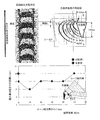
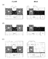
図24に、記録媒体の磁界強度の等高線と磁化反転形状を示す。主磁極は、トラック幅40nm,膜厚100nm及びBevel角9degの単磁極の記録ヘッドを用いた。図24(a)は、等高線図の右側に主磁極の浮上面形状を示し、記録媒体側の磁界強度3kOeから7kOeの等高線の片側を示す。主磁極の記録磁界強度の等高線は、主磁極の中心部を最大強度として同心円状に分布し、等高線の外側ほど膨らんだ分布を示して磁界強度6kOeの等高線は主磁極に付与されたBevel角と同等の磁気的逃げ角を発生させている。したがって、磁気的逃げ角は主磁極のBevel角に依存しており、Bevel角の効果により主磁極のトレーリング側とリーディング側の磁界強度差を設けていることが分かる。 FIG. 24 shows the contour lines of the magnetic field strength and the magnetization reversal shape of the recording medium. As the main magnetic pole, a single magnetic pole recording head having a track width of 40 nm, a film thickness of 100 nm and a Bevel angle of 9 deg was used. FIG. 24A shows the shape of the air bearing surface of the main pole on the right side of the contour map, and shows one side of the contour line with a magnetic field intensity of 3 kOe to 7 kOe on the recording medium side. The contour line of the recording magnetic field strength of the main magnetic pole is distributed concentrically with the central portion of the main magnetic pole as the maximum intensity, and shows a distribution that swells toward the outer side of the contour line. The contour line of the magnetic field strength of 6 kOe is the Bevel angle applied to the main magnetic pole. Equivalent magnetic clearance angle is generated. Therefore, it can be seen that the magnetic clearance angle depends on the Bevel angle of the main magnetic pole, and the magnetic field strength difference between the trailing side and the leading side of the main magnetic pole is provided by the effect of the Bevel angle.
図24(b)は、記録媒体に記録された磁化状態をシミュレーションにより得た図である。記録磁化反転形状は記録磁界強度が記録媒体の保磁力と等しくなる等高線の形状を反映して決定されると考えられ、記録媒体の走行方向のトラック中心からトラック端部に向かって湾曲していることが分かる。この湾曲は、磁気抵抗効果型再生ヘッドで再生する際に磁化反転幅が大きく見えて弧立波の半値幅が増大すると同時に、記録トラック幅が線記録密度の上昇に伴い狭められる問題が生じるため、高記録密度を実現するためには等高線の磁気的逃げ角の発生する位置をトレーリング側に近づけて湾曲率を小さくしなければならない。 FIG. 24B is a diagram obtained by simulating the magnetization state recorded on the recording medium. The recording magnetization reversal shape is considered to be determined by reflecting the contour line shape in which the recording magnetic field strength is equal to the coercive force of the recording medium, and is curved from the track center in the running direction of the recording medium toward the track end. I understand that. This curvature causes a problem that the recording reversal width appears to be large when reproducing with the magnetoresistive effect type reproducing head and the half-value width of the standing wave increases, and at the same time, the recording track width is narrowed as the linear recording density increases. In order to achieve a high recording density, the curvature must be reduced by bringing the magnetic relief angle of the contour lines close to the trailing side.
本発明の磁気記録ヘッドは、主磁極の浮上面から後退した素子高さ方向のスロートハイト部及びフレア部のトレーリング側に張り出した磁性膜を設けたところが特徴である。この張り出した磁性膜からの磁束は、主磁極のトレーリング側及び側面から主磁極に流れ込み、主磁極全体の磁界強度を増強しながらトレーリング側とリーディング側の磁界強度差が大きくなる。 The magnetic recording head of the present invention is characterized in that a throat height portion in the element height direction that has receded from the air bearing surface of the main magnetic pole and a magnetic film that protrudes to the trailing side of the flare portion are provided. The magnetic flux from the protruding magnetic film flows into the main pole from the trailing side and side surface of the main pole, and the magnetic field strength difference between the trailing side and the leading side increases while increasing the magnetic field strength of the entire main pole.
本発明によれば、主磁極のトレーリング側に張り出した磁性膜の付与により、主磁極側に磁束が流れ込み、トレーリング側の磁界強度が増加する効果がある。さらに、トレーリング側とリーディング側との磁界強度差が大きくなることから、主磁極に付与されたBevel角よりも大きな磁気的逃げ角を発生する効果がある。これにより、記録ヘッドの狭小化されて書き込み能力が低下した主磁極において、高い磁界勾配と強い磁界強度の書き込み能力を得ながら、記録媒体への記録磁界は、スキュー角が付いても隣接するトラックに対して充分な磁気的逃げ角と磁化反転形状の湾曲の少ないビットを記録できる効果を有する磁気記録ヘッドを提供することができる。 According to the present invention, the provision of the magnetic film projecting to the trailing side of the main magnetic pole has an effect that the magnetic flux flows into the main magnetic pole side and the magnetic field strength on the trailing side is increased. Furthermore, since the magnetic field strength difference between the trailing side and the leading side is increased, there is an effect of generating a magnetic clearance angle larger than the Bevel angle applied to the main pole. As a result, the recording magnetic field to the recording medium can be applied to the adjacent track even if a skew angle is applied, while obtaining a high magnetic field gradient and a high magnetic field strength writing ability in the main pole whose recording head is narrowed and the writing ability is reduced. In contrast, it is possible to provide a magnetic recording head having an effect of recording a sufficient magnetic relief angle and a bit having a small magnetization reversal shape.
以下、図面を参照して本発明の実施の形態を説明する。以下の図において同様の機能部分には同じ符号を付して説明する。
なお、本発明の主磁極のトレーリング側に張り出した磁性層の部分は、主磁極と機能が異なるため、以下では、主磁極から分離した構造体としてルーフ磁性層の名称を用いて記述する。ルーフ磁性層とは、主磁極のスロートハイト部からフレア部のトレーリング側を包みこむように張り出し、次第に素子高さ方向で膜厚の増加する領域を有する磁性膜である。
Embodiments of the present invention will be described below with reference to the drawings. In the following drawings, the same functional parts will be described with the same reference numerals.
The portion of the magnetic layer that protrudes to the trailing side of the main magnetic pole of the present invention has a function different from that of the main magnetic pole. Therefore, hereinafter, the structure separated from the main magnetic pole will be described using the name of the roof magnetic layer. The roof magnetic layer is a magnetic film that protrudes from the throat height portion of the main pole so as to wrap around the trailing side of the flare portion and has a region where the film thickness gradually increases in the element height direction.
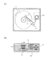
図1は、磁気記録再生装置の概念図である。磁気記録媒体(垂直磁気ディスク)11はモータ28により回転駆動される。情報の入出力時に、回転する磁気記録媒体11上の所定位置へサスペンションアーム12の先端に固定されたスライダー13が移動して、スライダー13に搭載された磁気ヘッドにより磁化信号の記録再生を行う。磁気ヘッドは、ロータリアクチュエータ15を駆動することにより、磁気記録媒体11の半径方向のトラック位置を選択することができる。記録ヘッドの記録信号及び再生ヘッドの読み出し信号は、信号処理回路35a,35bにて処理される。
FIG. 1 is a conceptual diagram of a magnetic recording / reproducing apparatus. The magnetic recording medium (perpendicular magnetic disk) 11 is rotationally driven by a
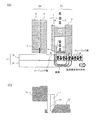
図2は、本発明による磁気ヘッドの断面模式図である。図2(a)は、本発明による磁気ヘッドの一例を示すトラック中心での断面模式図、図2(b)は、浮上面側の主磁極先端付近の拡大図である。 FIG. 2 is a schematic sectional view of a magnetic head according to the present invention. 2A is a schematic cross-sectional view at the center of a track showing an example of the magnetic head according to the present invention, and FIG. 2B is an enlarged view of the vicinity of the tip of the main magnetic pole on the air bearing surface side.
この磁気ヘッドは、主磁極1とリターン磁極3とを備えた単磁極の記録ヘッド25と、磁気抵抗効果型再生ヘッド24を有する記録再生複合ヘッドである。巨大磁気抵抗効果素子(GMR)やトンネル磁気抵抗効果型素子(TMR)などからなる再生素子4は、リーディング側の下部シールド8とトレーリング側の上部シールド9からなる一対の磁気シールド(再生シールド)間に配置されている。記録ヘッド25の主磁極1とリターン磁極3は、浮上面から離れた素子高さ方向の位置でピラー17により磁気的に接続され、主磁極1とリターン磁極3とピラー17と磁気記録媒体11によって構成される磁気回路に薄膜コイル2が周回されている。主磁極1は、ピラー17と接続されている主磁極ヨーク部1bと書き込み幅を規定するスロートハイト部とスロートハイト部と一体形成され素子高さ方向に向かって次第に幅の広がるフレア部からなる主磁極書き込み部1aで構成され、本発明のルーフ磁性層5が主磁極書き込み部1aをトレーリング側から包みこむように浮上面の素子高さ方向に形成され、次第に膜厚の増加する領域を有している。
This magnetic head is a recording / reproducing composite head having a single magnetic
主磁極1aには、例えば、Co,Ni,Feのうち少なくとも2種の元素を含む高い飽和磁束密度Bsを有する磁性体の単層膜や積層膜及び合金膜を用いることができる。主磁極ヨーク部1bの材料としては、例えば、Co,Ni,Feの2種以上の元素を含む高い透磁率の磁性材料が用いられる。本発明のルーフ磁性層5は、主磁極1aと一体構造でも良い。分離構造の場合、主磁極1aと異なる、例えば、Co,Ni,Feのうち少なくとも2種の元素を含む高い飽和磁束密度Bsを有する磁性体の単層膜,積層膜や合金膜及びめっき膜を用いることができる。
For the main magnetic pole 1a, for example, a single layer film, a laminated film, or an alloy film of a magnetic material having a high saturation magnetic flux density Bs containing at least two elements of Co, Ni, and Fe can be used. As a material of the main magnetic
記録ヘッド25の主磁極1aから放出された磁界は、磁気記録媒体11の磁気記録層19及び軟磁性裏打ち層(SUL:soft under layer)20を通ってリターン磁極3に入り、磁気記録層19に磁化パターンが記録される。この磁化パターン形状は、主磁極1の書き込み性能と浮上面側に設けられた磁気シールド32により規定される。
The magnetic field emitted from the main magnetic pole 1 a of the
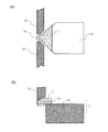
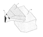
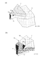
図3は、本発明による垂直磁気記録ヘッドの一実施例による主磁極を抜き出した平面と側断面の模式図である。図4は、本発明による垂直磁気記録ヘッドの一実施例による主磁極とルーフ磁性層を抜き出した模式図である。 FIG. 3 is a schematic view of a plane and a side cross-section from which the main pole is extracted according to an embodiment of the perpendicular magnetic recording head according to the present invention. FIG. 4 is a schematic view of the main magnetic pole and the roof magnetic layer extracted from one embodiment of the perpendicular magnetic recording head according to the present invention.
図3,図4に示した実施例について説明する。本実施例の場合、図3(a)(b)に示すように、主磁極1aは、非磁性層を介して三方をシールド32に囲まれ、主磁極1aの磁気記録媒体への磁束の放出が規制され、主磁極1aのトラック幅を規定するスロートハイト部とフレア部にルーフ磁性層5を備えている。図3(a)に示すルーフ磁性層5は、浮上面の主磁極1aのトラック幅より広く設定され、主磁極1aは主磁極ヨーク部1bに磁気的に接続されている。また、図3(b)に示すように、主磁極1aを側面から見た場合、ルーフ磁性層5は素子高さ方向に膜厚が増加するテーパ形状部を有して設定膜厚において平坦化になる。図4に示すように、ルーフ磁性層5の一部は、主磁極1aのトレーリング側の両側面まで延長されて主磁極1aのスロートハイト部及びフレア部のトレーリング側を包み込むように形成されている。一体形状の場合は、トラック方向に磁性体が張り出した構造となる。
The embodiment shown in FIGS. 3 and 4 will be described. In the case of the present embodiment, as shown in FIGS. 3A and 3B, the main magnetic pole 1a is surrounded by the
このような形態にすることにより、主磁極1aのトラック幅より広いルーフ磁性層5からトレーリング側に磁束を供給して、主磁極1a自体の磁界強度を高めながら書き込み磁極のトレーリング側とリーディング側の磁界強度差を大きくできる効果がある。さらに主磁極1aは、トレーリング側の両側面から局所的に磁束が供給されることにより、書き込み磁極の浮上面形状で規定されている書き込み磁界強度分布を変化させて、主磁極1aのBevel角に依存していた磁気的逃げ角を大きくする効果をもたらす特徴がある。
By adopting such a configuration, a magnetic flux is supplied from the roof
図3に示した本発明による磁気記録ヘッドと従来形状の磁気記録ヘッドについて、記録性能を表す磁界強度と磁界勾配及び磁気的逃げ角等を3次元磁界計算した。 For the magnetic recording head according to the present invention shown in FIG. 3 and the conventional magnetic recording head, the magnetic field strength, magnetic field gradient, magnetic clearance angle and the like representing the recording performance were calculated in a three-dimensional magnetic field.
図5に、3次元磁界計算に用いた本発明の磁気記録ヘッドのモデル条件を示す。本発明の記録ヘッドは、主磁極1aのトラック幅40nm、膜厚100nm、Bevel角9degとし、浮上面までのスロートハイトを30nmとし、スロートハイト規定部から幅の広がるフレア部の素子高さ方向4.9μmとし、主磁極とサイドシールドの間隔100nm,トレーリング間隔25nm,シールドの素子高さ方向100nmとした。本発明のルーフ磁性層5は、主磁極1aのトレーリング側と側面を包み込むように、浮上面からの素子高さ方向15nmからフレア部4.9μmまで主磁極1aの幅より20nm大きく、トレーリング側の膜厚60nm,テーパ角度20degとした。磁気ヘッドと記録媒体の位置関係は、磁気ヘッドと記録媒体の距離10nm、磁気ヘッドと記録媒体の裏打ち層までの距離59.5nmとした。ルーフ磁性層5を浮上面より素子高さ方向に後退させる理由は、ルーフ磁性層5からの磁束が記録媒体11へ直接書き込まないようにするためであり、記録媒体に対する磁気ヘッドの浮上量よりも15nm以上離すことにより、ルーフ磁性層5からの磁束漏れによる書き込みトラックの書き滲みを低減している。また、書き込みトラックの書き滲み低減の観点から、主磁極1aのトレーリング側の側面に付ける磁性層の断面積は微小面積にして、本発明の効果を得る必要から幅20nm以下で両側に付与することが好ましい。
FIG. 5 shows model conditions of the magnetic recording head of the present invention used for the three-dimensional magnetic field calculation. In the recording head of the present invention, the track width of the main magnetic pole 1a is 40 nm, the film thickness is 100 nm, the Bevel angle is 9 deg, the throat height to the air bearing surface is 30 nm, and the
本発明の記録ヘッドと比較した比較例1の従来記録ヘッドは、主磁極1aに単磁極を用いたルーフ磁性層の無い記録ヘッドである。その他は主磁極形状,シールド間隔及びシールド素子高さ方向等の条件は本発明と同じ条件を用いた。 The conventional recording head of Comparative Example 1 compared with the recording head of the present invention is a recording head without a roof magnetic layer using a single magnetic pole as the main magnetic pole 1a. Otherwise, the same conditions as in the present invention were used for the main magnetic pole shape, shield interval, shield element height direction, and the like.
比較例2の記録ヘッドは、書き込み能力が低くなるが本発明の効果を示すために、主磁極1aのトレーリング側にルーフ磁性層5が無く、主磁極1aのトレーリング側の側面にのみ幅10nm,膜厚30nmの磁性層を配置した構造を用いた。その他は主磁極形状,シールド間隔及びシールド素子高さ方向等の条件は本発明と同じ条件を用いた。
In the recording head of Comparative Example 2, although the writing ability is lowered, the roof
主磁極1の書き込み部1a及びルーフ磁性層5の材料としては、コバルトニッケル鉄(CoNiFe)を想定し、飽和磁束密度を2.4T,比透磁率500とした。主磁極ヨーク部1bは、飽和磁束密度1.0T,比透磁率1500の80at%Ni−20at%Feを想定した。シールド32は、飽和磁束密度1.0T,比透磁率1500の80at%Ni−20at%Feを想定した。磁気記録媒体11の軟磁性裏打ち層20の材料としては、CoTaZrを想定し、膜厚60nmとした。書き込み特性等は、ヘッド浮上面から22nmの磁気記録層中心位置を想定した位置で算出した。記録媒体11の媒体記録層は、厚さ20nmとして磁化特性は考慮しなかった。
Cobalt nickel iron (CoNiFe) is assumed as the material of the writing portion 1a of the main
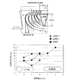
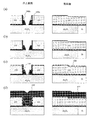
図6は、図5の計算モデルを用いて計算した本発明の記録ヘッドの磁界強度の等高線と磁気的逃げ角の関係を示す図である。磁気的逃げ角は、磁気記録ヘッドにスキュー角が無い状態において、最も書き幅の広いトラック幅から記録媒体の走行方向に対してリーディング側の磁界強度の等高線の角度を各磁界強度から算出した。 FIG. 6 is a diagram showing the relationship between the contour lines of the magnetic field strength of the recording head of the present invention calculated using the calculation model of FIG. 5 and the magnetic clearance angle. The magnetic clearance angle was calculated from the magnetic field strength from the angle of the contour line of the magnetic field strength on the reading side with respect to the running direction of the recording medium from the track width with the widest writing width when the magnetic recording head had no skew angle.
本発明の記録ヘッドは、図5に示すように、主磁極1aのトレーリング側に膜厚60nm,テーパ角度20deg,スロートハイト部のトラック幅より20nm広く、かつトレーリング側の側面には幅10nm,深さ方向の長さΔTを30nmとしたルーフ磁性層5で主磁極1aを包みこむように形成した。
As shown in FIG. 5, the recording head of the present invention has a film thickness of 60 nm on the trailing side of the main pole 1a, a taper angle of 20 degrees, a width of 20 nm wider than the track width of the throat height portion, and a width of 10 nm on the side surface on the trailing side. The main magnetic pole 1a is surrounded by the roof
比較例1の単磁極の記録ヘッドによる磁気的逃げ角は、Bevel角と同じ9degを示し、等高線の磁界強度の低下によりBevel角よりも小さな磁気的逃げ角となり書き込みトラックに隣接するトラック情報を減衰及び消去する問題が生じる。比較例2の記録ヘッドは、主磁極1aのBevel角9degよりも大きな磁気的逃げ角14degを発生して、Bevel角9degを維持しながらサイドシールド32に磁束が吸われている。つまり、主磁極1aのトレーリング側の側面に付いた磁性層は、主磁極1aへ磁束が流れ込みトレーリング側とリーディング側の磁界強度分布の差を大きくして磁気的逃げ角を主磁極1aの幾何Bevel角よりも大きくする効果がある。
The magnetic clearance angle by the single magnetic pole recording head of Comparative Example 1 is 9 deg, which is the same as the Bevel angle, and the magnetic field angle of the contour line is decreased to become a magnetic clearance angle smaller than the Bevel angle, thereby attenuating track information adjacent to the writing track. And erasure problems arise. The recording head of Comparative Example 2 generates a
本発明の記録ヘッドの特徴は、比較例2の効果を用いて主磁極1aのトレーリング側及び側面にも磁性層を積層したルーフ磁性層5にある。ルーフ磁性層5を備えることにより、高い8kOeの磁界強度を放出しながら、磁界強度8kOeの等高線において主磁極1aのBevel角9degの2倍に相当する18degの磁気的逃げ角を発生させ、Bevel角よりも大きな磁気的逃げ角を維持してサイドに配置したシールド32に磁束が吸われる。
A characteristic of the recording head of the present invention is the roof
本発明の記録ヘッドは、ルーフ磁性層5を備えることにより、高い書き込み磁界強度を得ながら主磁極1aのトレーリング側とリーディング側の磁界強度分布差を大きくすることが可能になり、磁気的逃げ角を大きくする効果がある。
Since the recording head of the present invention includes the roof
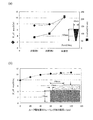
図7に、図5で用いた計算モデルよる磁界強度及び磁界勾配の関係を示す。図7(a)は、本発明の記録ヘッドの磁界強度と磁界勾配の関係を示す。本発明の記録ヘッドは、主磁極1aのトレーリング側を包みこむようにルーフ磁性層5を備えることにより、比較例1及び主磁極1aのトレーリング側の側面にのみ磁性層を備えた比較例2よりも磁界強度及び磁界勾配を改善し、書き込み能力を高める効果がある。
FIG. 7 shows the relationship between the magnetic field strength and the magnetic field gradient according to the calculation model used in FIG. FIG. 7A shows the relationship between the magnetic field strength and the magnetic field gradient of the recording head of the present invention. The recording head of the present invention includes the roof
図7(b)に、ルーフ磁性層のトレーリング側の膜厚tと磁界強度の関係を示す。主磁極1aのトレーリング側のルーフ膜厚は、ルーフ磁性層5の浮上面側と平坦部の位置の位置を変えずに膜厚を変化させている。主磁極1aのトレーリング側のルーフ磁性層5の磁界強度は、膜厚に依存して増加傾向を示すが、80nm〜100nmから磁界強度の変化量が小さくなる。ルーフ磁性層を主磁極1aのトレーリング側に、膜厚100nm以上に積層しても磁界増強効果は小さいものと推定される。
FIG. 7B shows the relationship between the film thickness t on the trailing side of the roof magnetic layer and the magnetic field strength. The roof film thickness on the trailing side of the main magnetic pole 1a is changed without changing the position of the air bearing surface side of the roof
図8に、図5の計算モデルを用いて、主磁極のトレーリング側とトレーリング側の側面に付けたルーフ磁性層の側面に付与された膜厚ΔT部を変化させた場合の磁界強度,磁界勾配の関係を示す。図8の横軸は、主磁極1aのトレーリング側の側面に付与されたルーフ磁性層5のΔT部の深さを示す。ルーフ磁性層の無い比較例1の磁界強度と磁界勾配を、図8の横軸0の位置にプロットする。本発明の記録ヘッドは、比較例1よりも大きく書き込み能力が改善されて、主磁極1aのトレーリング側の側面に付与したルーフ磁性層5のΔT部が10nm以上ならば磁界強度を増加させる効果もある。磁界勾配に関しては、磁界強度が増加しても20nm以上の膜厚では一定値を示している。
FIG. 8 shows the magnetic field strength when the thickness ΔT portion applied to the side surface of the roof magnetic layer attached to the trailing side and the side surface of the trailing side of the main pole is changed using the calculation model of FIG. The relationship of magnetic field gradient is shown. The horizontal axis of FIG. 8 shows the depth of the ΔT portion of the roof
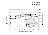
図9に、図5の計算モデルを用いて計算した磁気的逃げ角とΔTの関係を示す。図9の横軸は、ΔTの異なる記録ヘッドの磁界強度を示す。磁気的逃げ角は、磁気記録ヘッドにスキュー角が無い状態において、最も書き幅の広いトラック幅から記録媒体の走行方向に対してリーディング側の磁界強度の等高線の角度を各磁界強度から算出した。ここで、ΔT=0は、ルーフ磁性層5が主磁極1aのトレーリング側だけに積層された記録ヘッドである。
FIG. 9 shows the relationship between the magnetic clearance angle calculated using the calculation model of FIG. 5 and ΔT. The horizontal axis in FIG. 9 indicates the magnetic field strength of the recording head having different ΔT. The magnetic clearance angle was calculated from the magnetic field strength from the angle of the contour line of the magnetic field strength on the reading side with respect to the running direction of the recording medium from the track width with the widest writing width when the magnetic recording head had no skew angle. Here, ΔT = 0 is a recording head in which the roof
本発明の記録ヘッドは、主磁極1aのBevel角よりも大きな磁気的逃げ角を維持しているが、ΔTの変化により磁気的逃げ角も大きくなる。主磁極1aの近傍にある磁界強度8kOeの等高線ではΔT=10nmで最も大きい磁気的逃げ角を発生し、ΔTの増加とともに低下する傾向にある。磁界強度7kOe〜5kOeの範囲では、磁気的逃げ角はΔTの増加で逆転する。この理由として、ΔT=10nmの場合には、主磁極のトレーリング側の側面に付与された磁性層から主磁極に入る磁束量が少ないために、高い磁界強度ではトレーリング側とリーディング側の磁界強度差が大きいが、低い磁界強度において磁界強度差を維持する磁束量が不足しているために磁気的逃げ角が低下すると推定される。しかし、主磁極1aのBevel角9degよりも磁気的逃げ角を大きくする効果があるため、ルーフ磁性層5のΔT膜厚は、主磁極1aの膜厚の1/2程度まで付与しても問題ないことが分かる。
The recording head of the present invention maintains a magnetic clearance angle larger than the Bevel angle of the main pole 1a, but the magnetic clearance angle also increases due to the change in ΔT. On the contour line with a magnetic field strength of 8 kOe in the vicinity of the main magnetic pole 1a, the largest magnetic clearance angle is generated at ΔT = 10 nm and tends to decrease as ΔT increases. In the range of the magnetic field strength of 7 kOe to 5 kOe, the magnetic clearance angle is reversed with an increase in ΔT. The reason for this is that when ΔT = 10 nm, the amount of magnetic flux entering the main pole from the magnetic layer applied to the side of the main pole on the trailing side is small. Although the intensity difference is large, it is presumed that the magnetic clearance angle decreases because the amount of magnetic flux that maintains the magnetic field intensity difference is insufficient at a low magnetic field intensity. However, since the magnetic clearance angle is larger than the Bevel angle of 9 deg of the main magnetic pole 1a, the ΔT film thickness of the roof
しかし、記録媒体に記録される記録磁化反転形状のトラック中心からトラック端部の湾曲の問題が残っている。図10は、図5の計算モデルを用いて計算した主磁極のトレーリング端面から書き幅までの距離LとΔTとの関係を示す。 However, there remains a problem of the curvature of the track end from the center of the track of the recording magnetization reversal shape recorded on the recording medium. FIG. 10 shows the relationship between the distance L from the trailing end face of the main pole to the writing width and ΔT calculated using the calculation model of FIG.
記録磁化反転形状は、記録磁界強度が記録媒体の保磁力と等しくなる等高線の形状を反映して決定されると考えられ、トレーリング側のシールド32による磁界勾配で決まる主磁極のトレーリング側の距離と主磁極の磁界分布で決まる距離Lで湾曲率が決められると推定される。この湾曲は、磁気抵抗効果型再生ヘッドで再生する際に磁化反転幅が大きく見えて弧立波の半値幅が増大すると同時に、記録トラック幅が線記録密度の上昇に伴い狭められるため、磁気的逃げ角の始まる位置の距離L値が小さければ、記録媒体11に書き込む磁化信号のトレーリング側の湾曲を小さくできる。湾曲が小さくなればビッツト長が短くなり、記録密度を向上できる。
The recording magnetization reversal shape is considered to be determined by reflecting the contour line shape in which the recording magnetic field strength is equal to the coercive force of the recording medium, and the main magnetic pole on the trailing side of the main pole determined by the magnetic field gradient by the
本発明の記録ヘッドは、磁界強度8kOeにおいて、距離LがΔT=10nmで最も小さく、ΔTを増すと距離Lは増加し、主磁極1aの膜厚の1/2であるΔT=50nmで比較例1と同等の距離Lになる。これは、ΔTが大きくなって主磁極1aのトレーリング側の側面に付けたルーフ磁性層がリーディング側に近づくと湾曲が大きくなることを示しており、主磁極1aの膜厚の中心までΔTを付与すると磁気的逃げ角を大きくできるが、記録磁化反転形状の湾曲も大きくなるため、ΔTは主磁極のトレーリング側のルーフ磁性層の付与された浮上面側の主磁極膜厚の1/2未満とすることが好ましい。 The recording head of the present invention is the smallest when the distance L is ΔT = 10 nm at a magnetic field intensity of 8 kOe, and the distance L increases as ΔT is increased, and the comparative example is ΔT = 50 nm which is ½ of the film thickness of the main pole 1a. The distance L is equal to 1. This indicates that when ΔT increases and the roof magnetic layer attached to the trailing side surface of the main pole 1a approaches the leading side, the curvature increases, and ΔT is increased to the center of the thickness of the main pole 1a. When applied, the magnetic clearance angle can be increased, but the curvature of the recording magnetization reversal shape also increases. Therefore, ΔT is ½ of the main magnetic pole film thickness on the air bearing surface side provided with the roof magnetic layer on the trailing side of the main magnetic pole. It is preferable to make it less than.
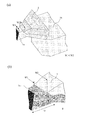
図11,図12に、本発明の他の実施例を示す。図11は、実施例2の主磁極周辺の拡大模式図を示す。図11に示した実施例2は、主磁極1aトラック幅W1とルーフ磁性層5のトレーリング側幅W2の関係がW1<W2において、ルーフ磁性層5のトレーリング側の側面に付与された磁性層のトレーリング側幅w2とリーディング側幅w1の関係がw1<w2の場合、主磁極1aのトレーリング側の側面から磁束を供給する手法は同様のために、磁気的逃げ角をBevel角よりも増大させる同様の効果が得られる。
11 and 12 show another embodiment of the present invention. FIG. 11 is an enlarged schematic view of the vicinity of the main magnetic pole according to the second embodiment. In Example 2 shown in FIG. 11, when the relationship between the track width W1 of the main pole 1a and the trailing side width W2 of the roof
図12は、実施例3の主磁極周辺の拡大模式図を示す。図12に示した実施例3は、主磁極1aのトラック幅W1とルーフ磁性層5のトレーリング側幅W2の関係がW1<W2において、ルーフ磁性層5のトレーリング側の側面に付与された磁性層の記録媒体と対向する面が浮上面側から素子高さ方向へ角度θで後退する領域を備えた場合、手法は同様のために、磁気的逃げ角をBevel角よりも増大させる同様の効果が得られ、利点として浮上面側のルーフ磁性層から記録媒体11への磁束の放出を低減できる。
FIG. 12 is an enlarged schematic view of the vicinity of the main magnetic pole according to the third embodiment. In Example 3 shown in FIG. 12, the relationship between the track width W1 of the main pole 1a and the trailing side width W2 of the roof
なお、本発明の効果を三次元磁界計算より説明するため、主磁極のスロートハイト部からフレア部のトレーリング側を包みこむように張り出し、次第に素子高さ方向で膜厚の増加する領域を有する磁性膜をルーフ磁性層と呼び、主磁極から分離した構造体として説明したが、これは主磁極とルーフ磁性層の部分の機能が異なるためであり、製造方法においては、主磁極1aとルーフ磁性層5を一体で形成しても同様の効果が得られる。 In order to explain the effect of the present invention from the three-dimensional magnetic field calculation, the magnetic pole has a region in which the trailing edge of the flared portion is wrapped from the throat height portion of the main pole and the film thickness gradually increases in the element height direction. The film is called a roof magnetic layer and has been described as a structure separated from the main magnetic pole because the functions of the main magnetic pole and the roof magnetic layer are different. In the manufacturing method, the main magnetic pole 1a and the roof magnetic layer are used. The same effect can be obtained even if 5 is integrally formed.
ルーフ磁性を有する本発明の磁気記録ヘッドの製造方法について説明する。本発明の磁気記録ヘッドは、次の工程を順次行い、主磁極とシールドを形成することによって製造できる。
(1) 基板の上面が平坦化され主磁極1のヨーク部1bの上面が露出した基板に無機絶縁膜を積層し、レジストパターンを形成する工程
(2) レジストパターンをマスクに無機絶縁膜をエッチングして段差を形成し、レジストを除去後に2層目の無機絶縁膜を積層し、レジストパターンを形成する工程
(3) レジストパターンをマスクに無機絶縁膜をエッチングし、溝を掘るための矩形の台座を形成する工程
(4) 矩形の台座の側面にサイドシールドを形成する電極層と矩形の台座の側面を保護する保護膜を順次積層する工程
(5) 有機樹脂を全面塗布する工程
(6) 有機樹脂を矩形の台座が露出するまでエッチングする工程
(7) 矩形の台座の中に主磁極となる逆台形の溝を形成する工程
(8) 矩形の台座の中のトラック幅から張り出したルーフ磁性膜となる溝を広げる工程
(9) 矩形の台座の中の溝を磁性めっき膜で埋めて主磁極とルーフ磁性膜を形成する工程
(10) 不要な磁性めっき膜を除去する工程
(11) 矩形の台座側面の保護膜を除去してサイドシールド層を形成する電極層を露出する工程
(12) レジストパターンを形成する工程
(13) レジストパターンを用いてサイドシールド層を磁性めっきで形成する工程
(14) 磁性膜を平坦化する工程
(15) 平坦化されて各部位の表面が露出した基板上に無機絶縁膜を積層し、レジストパターンを形成する工程
(16) レジストパターンをマスクに無機絶縁膜とサイドシールドと矩形の台座及び溝内の磁性層をエッチングする工程
(17) トレーリング側のシールド用の電極層を積層する工程
(18) レジストパターンを形成する工程
(19) レジストパターンをマスクにトレーリング側のシールド用の磁性めっき層を形成する工程
A method for manufacturing the magnetic recording head of the present invention having roof magnetism will be described. The magnetic recording head of the present invention can be manufactured by sequentially performing the following steps to form a main pole and a shield.
(1) A step of forming a resist pattern by laminating an inorganic insulating film on a substrate where the upper surface of the substrate is flattened and the upper surface of the
(2) A step of forming a step by etching the inorganic insulating film using the resist pattern as a mask to form a step, laminating the second inorganic insulating film after removing the resist, and forming a resist pattern
(3) Etching the inorganic insulating film using the resist pattern as a mask to form a rectangular pedestal for digging a groove
(4) Step of sequentially laminating an electrode layer for forming a side shield on the side surface of the rectangular pedestal and a protective film for protecting the side surface of the rectangular pedestal
(5) Process to apply organic resin over the entire surface
(6) Etching organic resin until the rectangular pedestal is exposed
(7) Forming a reverse trapezoidal groove to be the main pole in the rectangular pedestal
(8) The process of widening the groove to become the roof magnetic film protruding from the track width in the rectangular pedestal
(9) Forming the main magnetic pole and the roof magnetic film by filling the grooves in the rectangular pedestal with a magnetic plating film
(10) Process to remove unnecessary magnetic plating film
(11) Step of exposing the electrode layer that forms the side shield layer by removing the protective film on the side surface of the rectangular pedestal
(12) Process for forming resist pattern
(13) Process of forming side shield layer by magnetic plating using resist pattern
(14) Flattening the magnetic film
(15) A process of forming a resist pattern by laminating an inorganic insulating film on a substrate that has been planarized and the surface of each part exposed.
(16) Etching the inorganic insulating film, side shield, rectangular pedestal and magnetic layer in the groove using the resist pattern as a mask
(17) Laminating a shielding electrode layer on the trailing side
(18) Process for forming resist pattern
(19) Forming a magnetic plating layer for the trailing shield using the resist pattern as a mask
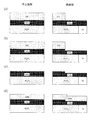
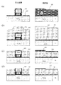
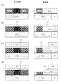
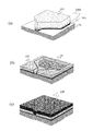
図13〜図22は、本発明の磁気記録ヘッド製造方法の一実施例を示す製造工程の概略図である。
図13は、主磁極1のヨーク部1bを製造した後、CMP(ケミカルメカニカルポリッシング)工程により平坦化された状態からの製造工程を示す。図中の左側が浮上面側から見た状態の概略図を示す。図中の右側に側面側からの概略図を示す。図中の右側の側面図の右下にヨーク部1bを示す。
13 to 22 are schematic views of manufacturing steps showing an embodiment of the magnetic recording head manufacturing method of the present invention.
FIG. 13 shows a manufacturing process from a state in which the
図13(a)は、基板の上面が平坦化され主磁極1のヨーク部1bの上面が露出した基板に無機絶縁膜100aを積層し、レジストパターン101を形成した工程を示す。無機絶縁膜100aは、例えば、Al,Si,Ta,Ti等の酸化物、窒化物等が使用可能である。このレジストパターン101をマスクに用いて、無機絶縁膜100aのエッチングを行ったところを、図13(b)に示す。イオンミリング法を用いて、Arを主ガスとしてエッチングして段差を形成する。エッチング後、レジストを除去したところを、図13(c)に示す。形成された段差の位置は、主磁極1aのトレーリング側のトラック幅方向に張り出した磁性膜の浮上面の位置に相当する。図12に示した実施例3の場合は、加工した段差部に素子高さ方向にテーパ角度をつけることでΔTにテーパを製造できる。図13(d)には、2層目の無機絶縁膜100bを積層した工程を示す。この2層目の無機絶縁膜100bは、下層の無機絶縁膜100aに対して加工方法のイオンミリング法,RIE法,RIM法において同等の加工速度を持ちながら、RIE法(リアクティブ・イオン・エッチング),RIM法(リアクティブ・イオン・ミリング)において、例えば、加工用の主ガスを塩素系ガス及びフッ素系ガスに変更することで高い選択加工速度を有する、例えば、Al,Si,Ta,Ti等の酸化物、窒化物等が使用できる。
FIG. 13A shows a process in which the resist
図14は、無機絶縁膜をエッチングし、溝を掘るための矩形の台座100を形成する工程を示す。矩形の台座100は、主磁極1aと同様のパターン形状を有しながら幅方向が主磁極1aより広く断面形状が長方形の形状で、主磁極1aとなる磁性体を支持する機能とサイドシールド32と主磁極1aの位置を規定する機能を有する非磁性体の構造物を指す。2層目の無機絶縁膜100bを積層し、レジストパターン104を形成した工程を、図14(a)に示す。このレジストパターン104としては、主磁極1aと同様の形状を有してトラック方向に幅広いパターンが形成される。レジストパターン104をマスクにして無機絶縁膜100aと100bを矩形にエッチングしたところを、図14(b)に示す。この工程の時、全体としては図25(a)のようになっている。矩形の台座100を主磁極1aと同様のBevel角を付けた逆台形形状としても良い。レジストパターン104を除去したところを、図14(c)に示す。
FIG. 14 shows a step of forming a
図15は、矩形の台座100の側面にサイドシールド32を形成する電極層102と矩形の台座の側面を保護する保護膜103を順次積層する工程と、有機樹脂105を全面に塗布する工程と、該有機樹脂105を該矩形の台座100の上面が露出するまでエッチングする工程を示す。
FIG. 15 shows a step of sequentially laminating an
図15(a)には、矩形の台座100の側面に後工程で形成するサイドシールド32の磁性めっき用の電極層102と保護膜103が、矩形台座100を被覆するように順次に積層されたところを示す。めっき用の電極層102としては、例えば、Cr,NiCr,Rh,Mo,Nb,Auの等の非磁性金属膜の単層膜や積層膜、また、Co,Ni,Feのうち少なくとも2種の元素を含む磁性材料の単層膜や積層膜を用いることができる。保護膜103は、めっき用の電極層102の酸化防止と矩形に加工した台座100のトラック方向への加工広がりを防止するため、例えば、後工程に用いるレジストやイミド系樹脂等の有機樹脂105との密着性が良く、ウェットエッチングで除去可能な、例えば、Cr,NiCrの単層膜や積層膜を用いることができる。図15(b)には、基板全面に有機樹脂105を回転塗布により全面に形成したところを示す。
In FIG. 15A, the
図15(c)には、矩形の台座100の上面が露出するまで有機樹脂105をRIM法(リアクティブイオンミリング)でエッチングしたところを示す。レジストやイミド系樹脂等の有機樹脂105のRIM法は、例えば、主ガスとして酸素系のガスを含むO2,CO,CO2等の単ガス及び混合ガスとArガスを添加して矩形の台座100の上面の膜が露出するまで行った。図15(d)には、矩形の台座100の上面に露出した保護膜103及び磁性めっき用の電極層102をイオンミリング法のエッチングで除去して、矩形の台座100の2層目の無機絶縁層100bの上面を露出させたところを示す。なお、有機樹脂105を矩形の台座100と同等の高さに設定する理由は、矩形の台座100のパターンよりも矩形の台座100が高い場合は、イオンミリング法のイオン入射を妨げるシャドー効果が起きて、矩形の台座100の底部まで加工されない現象が発生する。
FIG. 15C shows a state where the
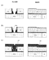
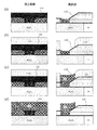
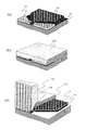
図16に、本発明のルーフ磁性層5を主磁極1aと一体で形成する製造工程の概略図を示す。図16は、矩形の台座100の中に逆台形の溝を形成する工程と、矩形の台座100の中の溝を広げる工程と、矩形の台座100の中の溝を磁性めっき膜109で埋める工程を示す。
FIG. 16 shows a schematic view of a manufacturing process for forming the roof
図16(a)に、矩形の台座100の無機絶縁層100a,100bにRIM法により逆台形形状の溝加工を行ったところを示す。RIM法は、フッ素系ガスのCHF3,CF4,C4F8等を主ガスとしてArガスを添加して、加工面に加工を阻害するCを堆積させながら行うことにより、逆台形形状の溝を形成できる。図16(b)には、上層の無機絶縁層100bを加工して溝幅を広げたところを示した。この工程の時、全体としては図25(b)のようになっている。無機絶縁層100bは、RIE法(リアクティブイオンエッチング)により、例えば、加工用の主ガスとして塩素系ガス及びフッ素系ガスを用いることで、無機絶縁層100aに対して高い選択加工速度で加工して無機絶縁層100aの界面でエッチングを止めることができる。図11に示したルーフ磁性層5のトレーリング側の側面に付与された磁性層のトレーリング側幅w2とリーディング側幅w1の関係がw1<w2の実施例2の場合、RIEの加工条件(電圧,電流,ガス量等)を変えることで容易に製造できる。矩形の台座100の中の溝を磁性めっき膜109で埋めるための電極層108を積層したところを、図16(c)に示す。電極層108としては、非磁性体を用いても、磁性体の例えば、Co,Ni,Feのうち少なくとも2主の元素を含む磁性材料の単層膜や積層膜を用いても良い。図16(d)には、電解めっき法を用いて磁性膜109をめっきしたところを示す。この工程の時、全体としては図25(c)のようになっている。電解めっき法を用いた場合、例えば、Co,Ni,Feのうち少なくとも2種の元素を含む高い飽和磁束密度Bsを有する磁性体の単層めっき膜や混合めっき膜を用いることができる。
FIG. 16A shows a case where a reverse trapezoidal groove is formed on the inorganic insulating
図17,図18には、ルーフ磁性層5と主磁極1aを分離して形成した実施例の製造工程の概略図を示す。
図17は、矩形の台座100の中に逆台形の溝を形成する工程と、矩形の台座100の中の溝を磁性めっき膜109で埋める工程を示す。図17(a)には、矩形の台座100の無機絶縁膜100a,100bを加工して逆台形形状の溝を形成したところを示す。この工程は、図16の(a)と同様の製造工程を用いている。逆台形に加工された溝に電解めっき用の電極層108aを積層したところを、図17(b)に示す。電極層108aは、非磁性体を用いても、磁性体の例えば、Co,Ni,Feのうち少なくとも2主の元素を含む磁性材料の単層膜や積層膜を用いても良い。図17(c)には、電解めっき法を用いて磁性膜109をめっきしたところを示す。電解めっき法を用いた場合、例えば、Co,Ni,Feのうち少なくとも2種の元素を含む高い飽和磁束密度Bsを有する磁性体の単層めっき膜や混合めっき膜を用いることができる。
17 and 18 are schematic views showing the manufacturing process of the embodiment in which the roof
FIG. 17 shows a step of forming an inverted trapezoidal groove in the
図18に、本発明のルーフ磁性層5と主磁極1aを分離して形成した実施例の製造工程の概略図を示す。図18は、磁性めっき膜109を主磁極1aの浮上面のトレーリング側高さまで除去する工程と、主磁極1aの飽和磁束密度Bsと同じか、あるいはそれ以上の飽和磁束密度Bsの磁性膜116を積層する製造工程を示す。図18(a)には、磁性めっき膜109を主磁極1aの浮上面のトレーリング側高さまでイオンミリング法を用いて除去したところを示す。イオンミリング法の主ガスとしてArガスを用いて無機絶縁層100bの約2倍の速度を持って磁性めっき膜109をエッチングできる。図18(b)には、RIE法(リアクティブイオンエッチング)により、例えば、加工用の主ガスとして塩素系ガス及びフッ素系ガスを用いて、無機絶縁層100bを加工して溝幅を広げたところを示す。図18(c)には、矩形の台座100の溝に磁性膜116を積層したところを示す。積層膜116は、スパッタリング法を用いて例えば、Co,Ni,Feのうち少なくとも2種の元素を含む主磁極1aと同じ飽和磁束密度Bsでも高い飽和磁束密度Bsを有する磁性体の単層や積層膜を用いることができる。
FIG. 18 shows a schematic view of a manufacturing process of an embodiment in which the roof
図17及び図18の製造方法を用いて、ルーフ磁性層5(主磁極のスロートハイト部からフレア部のトレーリング側を包みこむように張り出した磁性膜)と主磁極1aを分離して形成できる。 17 and 18, the roof magnetic layer 5 (a magnetic film projecting so as to wrap around the trailing side of the flare portion from the throat height portion of the main pole) and the main pole 1a can be formed separately.
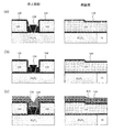
図19は、不要な磁性めっき膜を除去する工程と、矩形の台座100側面の保護膜103を除去してサイドシールド層32を形成する電極層102を露出する工程と、レジストパターン112を形成する工程を示す。
FIG. 19 shows a step of removing an unnecessary magnetic plating film, a step of removing the
図19(a)には、不要な磁性膜109を、イオンミリング法を用いて除去したところを示す。イオンミリング法では、Arを主ガスとして基板に対して低角度になる入射角55度から70度を用いて、矩形の台座100の溝内にある磁性膜109のエッチングを低減しながら周辺にある磁性膜109を除去して、矩形の台座100の側面にある有機樹脂105を露出させる。図19(b)には、有機樹脂105を除去したところを示す。矩形の台座100の側面には、主磁極1aの側面に備えるシールド32の前記製造工程で積層しためっき用の電極層102の酸化防止と矩形に加工された台座100の加工広がりを防止するために積層した保護膜103の面が露出される。
FIG. 19A shows a state where the unnecessary
図19(c)には、保護膜103を除去して、主磁極1aの側面に備えるシールド32用のめっき用電極層102を露出させたところを示す。保護膜102は、例えば、Cr,NiCrの単層膜や積層膜のウェットエッチングで除去できる膜を用いると良い。図19(d)には、めっき電極層102の表面を軽くイオンミリング法を用いて酸化膜を除去した後に、磁極1aの側面に備えるシールド32用のレジストパターン112を形成したところを示す。
FIG. 19C shows a state where the
図20は、レジストパターン112を用いて主磁極1aの側面に備えるシールド32のサイドシールド層を磁性めっきで形成する工程と、磁性膜を平坦化する前工程を示す。図20(a)には、主磁極1aの側面に備えるシールド32を電解めっき法で形成したところを示す。この工程の時、全体としては図26(a)に示すようになっている。シールド32としては、例えば、Co,Ni,Feのうち少なくとも2種の元素を含む磁性材料の磁性めっき膜を用いる。図20(b)には、レジストパターン112を除去したところを示す。図20(c)には、CMP法(ケミカルメカニカルポリッシング)を用いて、磁性膜の平坦化する前工程としてAl2O3膜を全面に積層したところを示す。
FIG. 20 shows a step of forming the side shield layer of the
図21は、平坦化された基板上に無機絶縁膜113を積層し、レジストパターン114を形成する工程と、レジストパターン114をマスクに無機絶縁膜113と主磁極の側面のシールド32と矩形の台座100及び溝内の磁性層109をエッチングする工程を示す。図21(a)には、CMP法により平坦化されて同一平面上に矩形の台座100,溝内の磁性体109,主磁極の側面のシールド32及びAl2O3膜の表面を露出させたところを示す。平坦化によるCMP法で各部位の残り膜厚を決めても良いが、イオンミリング法を併用して残り膜厚を決めても良い。図21(b)では、平坦化された基板上に無機絶縁膜113を積層する。この工程の時、全体としては図26(b)のようになっている。無機絶縁膜113としては、例えば、Al,Si,Ta,Ti等の酸化物、窒化物等を用いることができる。積層した無機絶縁膜上にレジストパターン114を形成したところを、図21(c)に示す。図21(d)には、レジストパターン114をマスクにして、無機絶縁膜113と主磁極の側面のシールド32と矩形の台座100及び溝内の磁性層109をイオンミリング法により加工したところを示す。イオンミリングのイオン入射角度を45度から60度として、レジストマスク近傍から浮上面側にテーパを有する形状に加工する。
FIG. 21 shows a step of laminating an inorganic
図22は、トレーリング側のシールド32のギャップ膜110を積層する工程と、レジストパターン115を形成する工程と、レジストパターン115をマスクにトレーリング側のシールド用の磁性めっき層を形成する工程を示す。図22(a)は、レジストパターン114を除去して、ギャップ膜110を積層して、主磁極の側面のシールド32の上面のギャップ膜110の一部をエッチング除去したところを示す。ギャップ膜110は、主磁極1aのトレーリング側のシールド32の磁性めっき用の電極層を兼ねるため、例えば、Cr,NiCr,Rh,Mo,Nb,Auの等の非磁性金属膜の単層膜や積層膜を用いることでギャップ層の機能も合わせ持たせる。主磁極の側面のシールド32とトレーリング側のシールド32の機能を合わせるために、ギャップ膜110の一部をエッチング除去して磁気的結合を持たせる。図22(b)には、トレーリング側のシールド32用のレジストパターン115を形成したところを示す。図22(c)には、主磁極1aのトレーリング側のシールド32を、電解めっき法により磁性めっきしたところを示す。この工程の時、シールドと無機絶縁層の一部を除去した場合は、主磁極1aの周辺は全体として図26(c)のようになっている。主磁極1aのトレーリング側のシールド32には、主磁極1aの側面のシールド32と同様の磁性膜を用いる。図22(d)には、レジストパターン115を除去したところを示す。本発明の製造工程により主磁極1aは、トレーリング側のトラック方向に張り出した磁性膜が付与されて非磁性層を介して三方からシールドに囲まれることになる。
FIG. 22 shows a step of laminating the
以上、説明したように、本発明に係る垂直磁気記録ヘッドは、主磁極と補助磁極を有する記録ヘッドと磁気抵抗効果型再生素子を備えた単磁極型の記録再生ヘッドを搭載した垂直記録方式の磁気ヘッドである。なお、主磁極1aの周辺に関する実施の形態を説明したが、本発明は上記の実施の形態に限定されるものではなく、記録ヘッドの書き込み磁極の浮上面の幾何トラック幅を広げることなく、浮上面より素子高さ方向のスロートハイト部から素子高さ方向のフレア部のトレーリング側の両側面及び上部に書き込み磁極の幾何学的トラック幅より広い補助磁極を設けた構造体を有する限り、製造方法及び材料、膜厚、形状等を変更することができる。 As described above, the perpendicular magnetic recording head according to the present invention is a perpendicular recording system equipped with a recording head having a main magnetic pole and an auxiliary magnetic pole, and a single magnetic pole type recording / reproducing head having a magnetoresistive effect reproducing element. It is a magnetic head. Although the embodiment relating to the periphery of the main magnetic pole 1a has been described, the present invention is not limited to the above-described embodiment, and the flying height can be increased without increasing the geometric track width of the air bearing surface of the write magnetic pole of the recording head. Manufactured as long as it has a structure in which auxiliary poles wider than the geometric track width of the write pole are provided on both sides of the flared part in the element height direction on the trailing side and the upper part of the flare part in the element height direction from the surface. The method and material, film thickness, shape, etc. can be changed.
1…主磁極、1a…書き込み磁極部、1b…主磁極ヨーク部、2…薄膜導体コイル、
3…リターン磁極、4…再生素子、5…ルーフ磁性層、8…下部シールド、9…上部シールド、11…磁気記録媒体、12…サスペンションアーム、13…磁気ヘッドスライダー、15…ロータリアクチュエータ、17…ピラー、19…磁気記録層、20…裏打ち層、24…再生ヘッド、25…記録ヘッド、28…モータ、32…シールド、100…矩形の台座、100a,100b…無機絶縁層、101…レジストパターン、102…電極層、103…保護膜、104…レジストパターン、105…有機樹脂、108…電極層、108a…電極層(分離形態)、109…磁性めっき層、110…ギャップ膜、112…レジストパターン、113…無機絶縁層、114…レジストパターン、115…レジストパターン、116…磁性層(分離形態)
DESCRIPTION OF
DESCRIPTION OF
Claims (11)
前記主磁極のトレーリング側及びトラック幅方向の両脇に非磁性層を介して配置された磁気シールドとを備え、
前記主磁極は、浮上面よりも素子高さ方向奥側のスロートハイト部及び前記フレア部にトレーリング側のトラック幅方向に張り出した磁性膜を有することを特徴とする磁気記録ヘッド。 A main pole having a throat height portion defining a recording track width on a facing surface facing the recording medium and a flare portion formed integrally with the throat height portion and gradually widening in the element height direction;
A magnetic shield disposed on the trailing side of the main magnetic pole and on both sides in the track width direction via a nonmagnetic layer;
The main magnetic pole has a throat height portion on the rear side in the element height direction with respect to the air bearing surface and a magnetic film projecting on the flare portion in the track width direction on the trailing side.
基板の上面が平坦化され主磁極のヨーク部の上面が露出した基板に第1の無機絶縁膜を形成する工程と、
前記無機絶縁膜に段差を形成し、その上に第2の無機絶縁膜を形成する工程と、
前記第2の無機絶縁膜をエッチングし、溝を掘るための矩形の台座を形成する工程と、
前記矩形の台座の側面にサイドシールドを形成する電極層と矩形の台座の側面を保護する保護膜を順次積層する工程と、
有機樹脂を全面塗布する工程と、
前記有機樹脂を前記矩形の台座が露出するまでエッチングする工程と、
前記矩形の台座の中に逆台形の溝を形成する工程と、
前記矩形の台座の中の溝を広げる工程と、
前記矩形の台座の中の溝を磁性めっき膜で埋める工程と、
不要な磁性めっき膜を除去する工程と、
前記矩形の台座側面の保護膜を除去してサイドシールド層を形成する電極層を露出する工程と、
サイドシールド層を磁性めっきで形成する工程と、
磁性膜を平坦化する工程と、
平坦化されて各部位の表面が露出した基板上に無機絶縁膜を積層し、レジストパターンを形成する工程と、
前記レジストパターンをマスクに前記無機絶縁膜と前記サイドシールドと前記矩形の台座及び溝内の磁性層をエッチングする工程と、
トレーリング側のシールド用の電極層を積層する工程と、
トレーリング側のシールド用の磁性めっき層を形成する工程と
を有することを特徴とする磁気記録ヘッドの製造方法。 A main pole having a throat height portion defining a recording track width on a facing surface facing the recording medium, a flare portion formed integrally with the throat height portion and gradually widening in the element height direction, and the main pole And a magnetic shield disposed on both sides in the track width direction via a nonmagnetic layer, and the main magnetic pole has a throat height portion and the flare portion on the rear side in the element height direction from the air bearing surface. A method of manufacturing a magnetic recording head having a magnetic film protruding in the track width direction on the trailing side,
Forming a first inorganic insulating film on the substrate where the upper surface of the substrate is planarized and the upper surface of the yoke portion of the main pole is exposed;
Forming a step in the inorganic insulating film and forming a second inorganic insulating film thereon;
Etching the second inorganic insulating film to form a rectangular pedestal for digging a groove;
A step of sequentially laminating an electrode layer forming a side shield on a side surface of the rectangular pedestal and a protective film protecting the side surface of the rectangular pedestal;
Applying organic resin over the entire surface;
Etching the organic resin until the rectangular pedestal is exposed;
Forming an inverted trapezoidal groove in the rectangular pedestal;
Expanding the groove in the rectangular pedestal;
Filling the groove in the rectangular pedestal with a magnetic plating film;
Removing unnecessary magnetic plating films;
Removing the protective film on the side surface of the rectangular pedestal to expose an electrode layer forming a side shield layer; and
Forming a side shield layer by magnetic plating;
A step of planarizing the magnetic film;
A step of laminating an inorganic insulating film on a substrate that has been planarized to expose the surface of each part, and forming a resist pattern;
Etching the inorganic insulating film, the side shield, the rectangular pedestal and the magnetic layer in the groove using the resist pattern as a mask;
Laminating a shielding electrode layer on the trailing side;
And a step of forming a magnetic plating layer for shielding on the trailing side.
Priority Applications (2)
| Application Number | Priority Date | Filing Date | Title |
|---|---|---|---|
| JP2008319571A JP2010146600A (en) | 2008-12-16 | 2008-12-16 | Perpendicular magnetic recording head, method of manufacturing the same, and magnetic recording/reproducing device |
| US12/636,667 US8335051B2 (en) | 2008-12-16 | 2009-12-11 | Perpendicular magnetic recording head having a magnetic layer overhanging a trailing side of a main pole and method of manufacture thereof |
Applications Claiming Priority (1)
| Application Number | Priority Date | Filing Date | Title |
|---|---|---|---|
| JP2008319571A JP2010146600A (en) | 2008-12-16 | 2008-12-16 | Perpendicular magnetic recording head, method of manufacturing the same, and magnetic recording/reproducing device |
Publications (1)
| Publication Number | Publication Date |
|---|---|
| JP2010146600A true JP2010146600A (en) | 2010-07-01 |
Family
ID=42240229
Family Applications (1)
| Application Number | Title | Priority Date | Filing Date |
|---|---|---|---|
| JP2008319571A Pending JP2010146600A (en) | 2008-12-16 | 2008-12-16 | Perpendicular magnetic recording head, method of manufacturing the same, and magnetic recording/reproducing device |
Country Status (2)
| Country | Link |
|---|---|
| US (1) | US8335051B2 (en) |
| JP (1) | JP2010146600A (en) |
Cited By (2)
| Publication number | Priority date | Publication date | Assignee | Title |
|---|---|---|---|---|
| US8208220B1 (en) | 2010-12-07 | 2012-06-26 | Tdk Corporation | Magnetic head, head assembly, and magnetic recording/reproducing apparatus to reduce risk of wide area track erase |
| US20140307349A1 (en) * | 2013-04-12 | 2014-10-16 | Western Digital (Fremont), Llc | Magnetic recording transducers having slim shaped additional poles |
Families Citing this family (9)
| Publication number | Priority date | Publication date | Assignee | Title |
|---|---|---|---|---|
| US8284516B1 (en) | 2011-04-08 | 2012-10-09 | Headway Technologies, Inc. | PMR write head with assisted magnetic layer |
| US8699183B2 (en) * | 2011-04-22 | 2014-04-15 | Seagate Technology Llc | Write pole and shield with different taper angles |
| US8570683B2 (en) * | 2011-06-24 | 2013-10-29 | HGST Netherlands B.V. | Low permeability material for a side shield in a perpendicular magnetic head |
| WO2013065093A1 (en) * | 2011-10-30 | 2013-05-10 | 株式会社日本マイクロニクス | Repeatedly chargeable and dischargeable quantum battery |
| US8830625B2 (en) | 2012-11-29 | 2014-09-09 | Seagate Technology Llc | Data writer with tapered side shield sidewalls |
| US9666212B2 (en) * | 2012-12-05 | 2017-05-30 | Seagate Technology Llc | Writer with protruded section at trailing edge |
| US8976493B1 (en) | 2013-12-11 | 2015-03-10 | HGST Netherlands B.V. | Magnetic read sensor with novel pinned layer and side shield design for improved data track resolution and magnetic pinning robustness |
| US10102871B1 (en) * | 2017-07-26 | 2018-10-16 | Seagate Technology Llc | High damping materials in shields and/or write pole |
| US10854224B1 (en) * | 2017-08-28 | 2020-12-01 | Seagate Technology Llc | Differential recessed topography of a media-facing surface |
Family Cites Families (7)
| Publication number | Priority date | Publication date | Assignee | Title |
|---|---|---|---|---|
| JP2007220209A (en) | 2006-02-16 | 2007-08-30 | Hitachi Global Storage Technologies Netherlands Bv | Magnetic head, magnetic recording / reproducing apparatus, and method of manufacturing magnetic head |
| JP2007220208A (en) | 2006-02-16 | 2007-08-30 | Hitachi Global Storage Technologies Netherlands Bv | Magnetic head, magnetic recording / reproducing apparatus, and method of manufacturing magnetic head |
| JP2007242132A (en) | 2006-03-08 | 2007-09-20 | Fujitsu Ltd | Perpendicular magnetic head |
| US8634162B2 (en) * | 2007-03-08 | 2014-01-21 | HGST Netherlands B.V. | Perpendicular write head having a stepped flare structure and method of manufacture thereof |
| JP2010092550A (en) * | 2008-10-09 | 2010-04-22 | Hitachi Global Storage Technologies Netherlands Bv | Magnetic recording head, method of manufacturing the same, and magnetic recording and reproducing device |
| US8259413B2 (en) * | 2008-12-31 | 2012-09-04 | Hitachi Global Storage Technologies Netherlands B.V. | Write head with self-align layer and a method for making the same |
| US8559123B2 (en) * | 2010-06-14 | 2013-10-15 | Tdk Corporation | Magnetic recording device, magnetic recording method and magnetic recording medium for shingle write scheme |
-
2008
- 2008-12-16 JP JP2008319571A patent/JP2010146600A/en active Pending
-
2009
- 2009-12-11 US US12/636,667 patent/US8335051B2/en active Active
Cited By (3)
| Publication number | Priority date | Publication date | Assignee | Title |
|---|---|---|---|---|
| US8208220B1 (en) | 2010-12-07 | 2012-06-26 | Tdk Corporation | Magnetic head, head assembly, and magnetic recording/reproducing apparatus to reduce risk of wide area track erase |
| US20140307349A1 (en) * | 2013-04-12 | 2014-10-16 | Western Digital (Fremont), Llc | Magnetic recording transducers having slim shaped additional poles |
| US8917480B2 (en) * | 2013-04-12 | 2014-12-23 | Western Digital (Fremont), Llc | Magnetic recording transducers having slim shaped additional poles |
Also Published As
| Publication number | Publication date |
|---|---|
| US8335051B2 (en) | 2012-12-18 |
| US20100149697A1 (en) | 2010-06-17 |
Similar Documents
| Publication | Publication Date | Title |
|---|---|---|
| JP2010146600A (en) | Perpendicular magnetic recording head, method of manufacturing the same, and magnetic recording/reproducing device | |
| JP5707453B2 (en) | Magnetic head for perpendicular magnetic recording with main pole and shield | |
| JP5571625B2 (en) | Magnetic head for perpendicular magnetic recording having a shield provided around the main pole | |
| JP5571624B2 (en) | Magnetic head for perpendicular magnetic recording with tapered main pole | |
| JP5571626B2 (en) | Magnetic head for perpendicular magnetic recording having a shield provided around the main pole | |
| JP5607680B2 (en) | Magnetic head for perpendicular magnetic recording with main pole and shield | |
| US7551395B2 (en) | Main pole structure coupled with trailing gap for perpendicular recording | |
| JP2007294059A (en) | Perpendicular magnetic head | |
| JP2007294078A (en) | Perpendicular magnetic recording type write head having notched trailing shield and manufacturing method | |
| JP2006004603A (en) | Thin film magnetic head and its manufacturing method, head gimbal assembly, and hard disk drive | |
| JP2009146517A (en) | Perpendicular magnetic recording head | |
| JP2006244671A (en) | Magnetic head and manufacturing method thereof | |
| JP2010061735A (en) | Magnetic head and method for manufacturing the same and information storage device | |
| US8351153B2 (en) | Magnetic recording head, method of manufacturing the same, and magnetic recording/reproducing device | |
| JP2009277314A (en) | Method for manufacturing thin film magnetic head | |
| JP4745892B2 (en) | Structure for thin film magnetic head, method of manufacturing the same, and thin film magnetic head | |
| US10839829B1 (en) | Magnetic head with a main pole including first and second layers and manufacturing method for the same | |
| JP2007004958A (en) | Thin-film magnetic head for perpendicular magnetic recording | |
| JP2008305513A (en) | Perpendicular magnetic recording head | |
| JP4970768B2 (en) | Structure for thin film magnetic head, method of manufacturing the same, and thin film magnetic head | |
| JP4116626B2 (en) | Magnetic head for perpendicular magnetic recording and manufacturing method thereof | |
| JP2007220208A (en) | Magnetic head, magnetic recording / reproducing apparatus, and method of manufacturing magnetic head | |
| JP5005274B2 (en) | Structure for thin film magnetic head, method of manufacturing the same, and thin film magnetic head | |
| JP2010135008A (en) | Magnetic head, manufacturing method thereof, and information storage device | |
| JP2008287790A (en) | Perpendicular magnetic recording head |