JP2010144597A - Control device for internal combustion engine - Google Patents
Control device for internal combustion engine Download PDFInfo
- Publication number
- JP2010144597A JP2010144597A JP2008321950A JP2008321950A JP2010144597A JP 2010144597 A JP2010144597 A JP 2010144597A JP 2008321950 A JP2008321950 A JP 2008321950A JP 2008321950 A JP2008321950 A JP 2008321950A JP 2010144597 A JP2010144597 A JP 2010144597A
- Authority
- JP
- Japan
- Prior art keywords
- egr
- internal combustion
- combustion engine
- control
- catalyst
- Prior art date
- Legal status (The legal status is an assumption and is not a legal conclusion. Google has not performed a legal analysis and makes no representation as to the accuracy of the status listed.)
- Pending
Links
Images
Classifications
-
- Y—GENERAL TAGGING OF NEW TECHNOLOGICAL DEVELOPMENTS; GENERAL TAGGING OF CROSS-SECTIONAL TECHNOLOGIES SPANNING OVER SEVERAL SECTIONS OF THE IPC; TECHNICAL SUBJECTS COVERED BY FORMER USPC CROSS-REFERENCE ART COLLECTIONS [XRACs] AND DIGESTS
- Y02—TECHNOLOGIES OR APPLICATIONS FOR MITIGATION OR ADAPTATION AGAINST CLIMATE CHANGE
- Y02T—CLIMATE CHANGE MITIGATION TECHNOLOGIES RELATED TO TRANSPORTATION
- Y02T10/00—Road transport of goods or passengers
- Y02T10/10—Internal combustion engine [ICE] based vehicles
- Y02T10/12—Improving ICE efficiencies
Landscapes
- Exhaust-Gas Circulating Devices (AREA)
Abstract
【課題】EGRクーラ及びEGR触媒のうちのいずれの能力が低下したかを適切に判別することが可能な内燃機関の制御装置を提供する。
【解決手段】内燃機関の制御装置は、EGR装置を備えた内燃機関に好適に適用される。判定手段は、EGR装置によってEGRガスを導入している際において、吸気圧においてピーク値が発生した際のクランク角における位相と、空燃比フィードバック制御における補正量とに基づいて、EGR触媒又はEGRクーラについての能力低下に対する判定を行う。これにより、EGRクーラ及びEGR触媒のうちのいずれの能力が低下したかを適切に判別することが可能となる。よって、吸気系のデポジット導入及びEGRクーラの目詰まりを効果的に抑制することが可能となる。
【選択図】図4A control device for an internal combustion engine capable of appropriately determining which of an EGR cooler and an EGR catalyst has deteriorated.
A control device for an internal combustion engine is preferably applied to an internal combustion engine having an EGR device. When the EGR gas is introduced by the EGR device, the determination means is based on the phase at the crank angle when the peak value is generated in the intake pressure and the correction amount in the air-fuel ratio feedback control, or the EGR catalyst or EGR cooler. Judgment is made for reduced ability. Thereby, it is possible to appropriately determine which of the EGR cooler and the EGR catalyst has deteriorated. Therefore, it is possible to effectively suppress deposit introduction of the intake system and clogging of the EGR cooler.
[Selection] Figure 4
Description
本発明は、EGR装置を備えた内燃機関の制御装置の技術分野に関する。 The present invention relates to a technical field of a control device for an internal combustion engine provided with an EGR device.
この種の技術が、例えば特許文献1に提案されている。特許文献1には、EGR装置におけるEGRクーラの冷却能力の低下を判定する技術が提案されている。具体的には、実吸気圧が正常吸気圧に対して一定以上低い場合に、EGRクーラの冷却能力が低下したと判定することが記載されている。 This type of technique is proposed in Patent Document 1, for example. Patent Document 1 proposes a technique for determining a decrease in the cooling capacity of an EGR cooler in an EGR device. Specifically, it is described that when the actual intake pressure is lower than the normal intake pressure by a certain level or more, it is determined that the cooling capacity of the EGR cooler has decreased.
しかしながら、特許文献1に記載の判定方法では、EGRクーラ及びEGR触媒を備えたEGR装置において、EGRクーラ及びEGR触媒のいずれの能力が低下したかを適切に判別することが困難であった。 However, in the determination method described in Patent Document 1, it has been difficult to appropriately determine which ability of the EGR cooler and the EGR catalyst has deteriorated in the EGR apparatus including the EGR cooler and the EGR catalyst.
本発明は、上記のような課題を解決するためになされたものであり、EGRクーラ及びEGR触媒のうちのいずれの能力が低下したかを適切に判別することが可能な内燃機関の制御装置を提供することを課題とする。 The present invention has been made to solve the above-described problems, and provides a control device for an internal combustion engine that can appropriately determine which of the EGR cooler and the EGR catalyst has deteriorated. The issue is to provide.
本発明の1つの観点では、少なくともEGR触媒及びEGRクーラを有するEGR装置を備えた内燃機関に適用される内燃機関の制御装置は、前記EGR装置によってEGRガスを導入している際において、吸気圧においてピーク値が発生した際のクランク角における位相と、空燃比フィードバック制御における補正量とに基づいて、前記EGR触媒又は前記EGRクーラについての能力低下に対する判定を行う判定手段を備える。 In one aspect of the present invention, an internal combustion engine control device applied to an internal combustion engine provided with an EGR device having at least an EGR catalyst and an EGR cooler is configured such that the intake air pressure is reduced when the EGR gas is introduced by the EGR device. Determination means for determining whether the EGR catalyst or the EGR cooler has a reduced capacity based on the phase at the crank angle when the peak value is generated and the correction amount in the air-fuel ratio feedback control.
上記の内燃機関の制御装置は、EGR装置を備えた内燃機関に好適に適用される。具体的には、判定手段は、EGR装置によってEGRガスを導入している際において、吸気圧においてピーク値が発生した際のクランク角における位相と、空燃比フィードバック制御における補正量とに基づいて、EGR触媒又はEGRクーラについての能力低下に対する判定を行う。これにより、EGRクーラ及びEGR触媒のうちのいずれの能力が低下したかを適切に判別することが可能となる。したがって、この判定結果に応じた制御を行うことにより、吸気系のデポジット導入及びEGRクーラの目詰まりを効果的に抑制することが可能となる。 The above control device for an internal combustion engine is preferably applied to an internal combustion engine including an EGR device. Specifically, when the EGR gas is introduced by the EGR device, the determination means is based on the phase at the crank angle when the peak value is generated in the intake pressure and the correction amount in the air-fuel ratio feedback control. Judgment is made with respect to a decrease in capacity of the EGR catalyst or EGR cooler. Thereby, it is possible to appropriately determine which of the EGR cooler and the EGR catalyst has deteriorated. Therefore, by performing control according to the determination result, it is possible to effectively suppress the intake system deposit introduction and clogging of the EGR cooler.
上記の内燃機関の制御装置の一態様は、前記判定手段は、前記吸気圧においてピーク値が発生した際のクランク角における位相と、予め定めた基準となる位相とのずれに基づいて、前記EGR装置におけるEGR通路内のガス温度を推定すると共に、前記空燃比フィードバック制御における補正量に基づいて、前記EGR触媒の状態を推定することで、前記判定を行うことができる。 In one aspect of the control apparatus for an internal combustion engine, the determination unit is configured to determine the EGR based on a shift between a phase at a crank angle when a peak value is generated in the intake pressure and a phase serving as a predetermined reference. The determination can be performed by estimating the gas temperature in the EGR passage in the apparatus and estimating the state of the EGR catalyst based on the correction amount in the air-fuel ratio feedback control.
上記の内燃機関の制御装置の他の一態様は、前記判定手段は、前記位相のずれより、前記EGR通路内のガス温度が低温であると推定された場合、前記EGRクーラが未暖機であると判定することができる。 According to another aspect of the control device for an internal combustion engine, when the determination unit estimates that the gas temperature in the EGR passage is low based on the phase shift, the EGR cooler is not warmed up. It can be determined that there is.
上記の内燃機関の制御装置の他の一態様は、前記判定手段は、前記位相のずれより、前記EGR通路内のガス温度が低温であると推定された場合において、前記空燃比フィードバック制御における補正量が所定値以下である場合、前記EGR触媒が未活性状態であると判定することができる。 According to another aspect of the control device for an internal combustion engine, the determination means corrects the air-fuel ratio feedback control when the gas temperature in the EGR passage is estimated to be low based on the phase shift. When the amount is not more than the predetermined value, it can be determined that the EGR catalyst is in an inactive state.
上記の内燃機関の制御装置において好適には、前記判定手段によって前記EGRクーラが未暖機であると判定された場合、前記EGRクーラへの冷却水量を減少させる制御を行う冷却水量制御手段を更に備える。これにより、EGRクーラが未暖機状態でのすす堆積に起因する、EGRクーラの目詰まりを適切に抑制することができる。 Preferably, the internal combustion engine control apparatus further includes a cooling water amount control unit that performs control to reduce a cooling water amount to the EGR cooler when the determination unit determines that the EGR cooler is not warmed up. Prepare. Thereby, the clogging of the EGR cooler caused by the soot accumulation when the EGR cooler is not warmed up can be appropriately suppressed.
また、好適には、前記判定手段によって前記EGR触媒が未活性状態であると判定された場合、EGRガス量を減少させる制御を行うEGRガス量制御手段を更に備える。これにより、EGR触媒の未活性状態でのEGRガス大量導入に起因する、吸気系へのデポジット導入を適切に抑制することができる。 Preferably, the apparatus further includes an EGR gas amount control unit that performs control to decrease the EGR gas amount when the determination unit determines that the EGR catalyst is in an inactive state. As a result, it is possible to appropriately suppress deposit introduction into the intake system due to large-scale introduction of EGR gas in an inactive state of the EGR catalyst.
以下、図面を参照して本発明の好適な実施の形態について説明する。 Preferred embodiments of the present invention will be described below with reference to the drawings.
[装置構成]
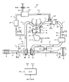
図1は、本発明の内燃機関の制御装置を適用した内燃機関の構成を示す構成図である。図1では、実線矢印がガス(吸気及び排気)の流れの一例を示し、破線矢印が信号の流れを示している。
[Device configuration]
FIG. 1 is a configuration diagram showing the configuration of an internal combustion engine to which the control device for an internal combustion engine of the present invention is applied. In FIG. 1, solid arrows indicate an example of a gas (intake and exhaust) flow, and broken arrows indicate a signal flow.
内燃機関(エンジン)は、自動車などの車両に走行用動力源として搭載され、主に、複数の気筒10と、各気筒10にそれぞれ接続される吸気通路3及び排気通路4と、吸気通路3及び排気通路4に設けられたターボ過給機5とを備えている。図1では、1つの気筒10のみを表示している。ターボ過給機5は、吸気通路3に設けられたコンプレッサ5aと、排気通路4に設けられたタービン5bと、を有し、これらが一体回転するように構成されている。
The internal combustion engine (engine) is mounted as a driving power source in a vehicle such as an automobile, and mainly includes a plurality of
吸気通路(吸気管)3には、エアクリーナ9と、エアフローメータ(AFM)41と、エアバイパス弁31と、ターボ過給機5のコンプレッサ5aと、インタークーラ6と、スロットルバルブ32と、吸気を貯蔵可能なサージタンク7と、が設けられている。AFM41は、外部から吸入された吸気の量(吸気量)を検出して、検出された吸気量に対応する検出信号S41をECU50へ送信する。エアバイパス弁31は、吸気通路3におけるコンプレッサ5aの上流側と下流側とを結ぶバイパス通路3aに設けられている。エアバイパス弁31は、バイパス通路3aを通過する吸気量を調整するためのものでありECU50からの制御信号によって制御される。例えば、スロットルバルブ32が急に閉じられた場合には、吸気通路3における吸気の圧力が急激に上昇するのを防ぐため、ECU50は、エアバイパス弁31を開いて、コンプレッサ5aにより圧縮された吸気をバイパス通路3aより逃がす。スロットルバルブ32は、吸気通路3における吸気量を調整するためのものであり、ECU50からの制御信号によって制御される。
In the intake passage (intake pipe) 3, an air cleaner 9, an air flow meter (AFM) 41, an
また、吸気通路3には、吸気温度センサ42と、吸気圧センサ43、44と、が設けられている。吸気温度センサ42は、吸気通路3における吸気の温度(吸気温度)を検出して、検出された吸気温度に対応する検出信号S42をECU50へ送信する。吸気圧センサ43、44は、吸気通路3における吸気圧(吸気管圧力を意味する。以下同じ。)を検出して、検出された吸気圧に対応する検出信号S43、S44をECU50へ送信する。
The intake passage 3 is provided with an intake
気筒10の燃焼室10aには、吸気通路3と排気通路4とが接続されているとともに、燃焼室10a内に燃料を噴射するための燃料噴射弁11と、燃焼室10a内において燃料に点火する点火プラグ12と、が設けられている。燃料噴射弁11と点火プラグ12とは、ECU50からの制御信号によって制御される。また、気筒10には、吸気弁13と排気弁14とが設けられている。吸気弁13は、開閉することによって、吸気通路3と燃焼室10aとの導通/遮断を制御する。排気弁14は、開閉することによって、排気通路4と燃焼室10aとの導通/遮断を制御する。吸気弁13が開くことにより、吸気通路3より燃焼室10a内へ吸気が導入される。燃焼室10a内へ導入された吸気は、燃料噴射弁11より噴射された燃料と混合した後、点火プラグ12が点火することにより燃焼される。燃焼により発生した排気は、排気弁14が開くことにより排気通路4へ排出される。燃焼室10a内で燃料と吸気とが燃焼されると、ピストン15が下死点まで押し下げられる力が発生する。ピストン15が下死点まで押し下げられる力が、コンロッド16を介してクランク軸17に伝達され、クランク軸17が回転する。ここで、クランク軸17近傍には、クランク角センサ45が設けられている。クランク角センサ45は、クランク軸17の回転角(クランク角)を検出して、検出されたクランク角に対応する検出信号S45をECU50へ送信する。また、気筒10の側面には、水温センサ48が取り付けられており、気筒10のウォータジャケット(不図示)における冷却水の水温を検出して、検出された水温に対応する検出信号S48をECU50へ送信する。
An intake passage 3 and an
排気通路4には、ターボ過給機5のタービン5bと、ウエストゲートバルブ36と、触媒8と、が設けられている。ウエストゲートバルブ36は、排気通路4におけるタービン5bの上流側と下流側とを結ぶバイパス通路4aに設けられている。ウエストゲートバルブ36は、バイパス通路4aを通過する排気量を調整するためのものであり、ECU50からの制御信号によって制御される。触媒8は、例えば三元触媒であり、炭化水素、一酸化炭素、窒素酸化物、などを浄化する機能を有する。なお、触媒8の代わりに、排気ガス中の粒子状物質を捕集するパティキュレートフィルタと触媒とを組み合わせた排気浄化装置を用いるとしてもよい。
In the
また、排気通路4には、空燃比センサ(A/Fセンサ)46が設けられている。A/Fセンサ46は、排気通路4における排気の空燃比を検出して、検出された空燃比に対応する検出信号S46をECU50へ送信する。A/Fセンサ46は、具体的には、酸素濃度センサである。酸素濃度センサは、その出力電圧の温度依存性が大きいため、酸素濃度の検出精度を良好に維持するには素子温度を適温(活性温度)に保つ必要がある。そのため、酸素濃度センサにはヒータが取り付けられている。ECU50は、このヒータの発熱により素子温度を活性温度(例えば約700℃以上)に保つようにヒータへの通電を制御している。
The
本実施形態に係る内燃機関では、排気ガス(EGRガス)を吸気側に還流させるためのEGR装置20が設けられている。EGR装置20は、主に、EGRガスが通過するEGR通路21と、EGRガスを浄化可能に構成されたEGR触媒22と、EGRガスを冷却水にて冷却するEGRクーラ23と、吸気側へ還流させるEGRガス量を調整可能に構成されたEGR弁33とを備える。EGR通路21は、一端がタービン5bの上流側の排気通路4に接続され、他端がスロットルバルブ32の下流側の吸気通路3に接続されている。詳しくは、EGR通路21は2つの通路21a、21bを備えており、これらの通路21a、21bよりEGRガスが導入される。つまり、排気2系統からEGRガスを取り出している。なお、EGR弁33は、ECU50から供給される制御信号S33によって制御される。
In the internal combustion engine according to the present embodiment, an
また、EGRクーラ23には、EGRガスを冷却するための冷却水が通過する冷却水通路24が接続されており、冷却水通路24より冷却水が供給される。この冷却水通路24上には、当該通路を通過する冷却水量を調整可能な冷却水弁25が設けられている。冷却水弁25は、ECU50から供給される制御信号S25によって制御される。
The
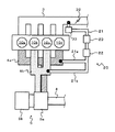
ここで、図2を参照して、上記したEGR装置20の具体的な構成について説明する。図2は、EGR装置20の構成を示す概略図である。ここでは、一例として、4つの気筒10a、10b、10c、10dを具備する内燃機関の構成を示す。また、図2では、排気通路4a、4dの違いをハッチングにて表すと共に、通路の接続箇所を黒丸にて表している。なお、図1に示した構成要素と同一の構成要素に対しては同一の符号を付すものとする。
Here, with reference to FIG. 2, a specific configuration of the
図示のように、気筒10a、10dには排気通路4aが接続されており、気筒10b、10cには排気通路4bが接続されている。そして、排気通路4aにEGR通路21における通路21aが接続され、排気通路4bにEGR通路21における通路21bが接続され、これらの通路21a、21bからEGRガスが導入される。なお、ターボ過給機5は、排気通路4a、4bよりタービン5bに排気ガスが供給されるように構成されている、つまりツインエントリターボ過給機として構成されている。
As illustrated, an
図1に戻って説明する。ECU(Electronic Control Unit)50は、図示しないCPU、ROM、RAM、A/D変換器及び入出力インターフェイスなどを有し、各種センサからの検出信号S41〜S46に基づいて内燃機関の運転状態を検出し、検出された運転状態に基づいて内燃機関の制御を行う。本実施形態では、主に、ECU50は、EGR触媒22及びEGRクーラ23のいずれの能力が低下したかを判別するための判定を行うと共に、この判定結果に応じた制御を行う。このように、ECU50は、本発明における内燃機関の制御装置として機能する。詳細は後述するが、ECU50は、判定手段、冷却水量制御手段、及びEGRガス量制御手段として動作する。
Returning to FIG. The ECU (Electronic Control Unit) 50 has a CPU, ROM, RAM, A / D converter, input / output interface, etc. (not shown), and detects the operating state of the internal combustion engine based on detection signals S41 to S46 from various sensors. Then, the internal combustion engine is controlled based on the detected operating state. In the present embodiment, the
[判定方法]
次に、本実施形態においてECU50が行う判定方法について、具体的に説明する。本実施形態では、ECU50は、EGR触媒22又はEGRクーラ23についての能力低下に対する判定を行う。具体的には、ECU50は、EGRガス導入時において、吸気圧においてピーク値が発生した際のクランク角における位相と、空燃比フィードバック制御における補正量とに基づいて、EGR触媒22又はEGRクーラ23のいずれの能力が低下したかを判別するための判定を行う。例えば、EGR触媒22が活性しているか否か、又はEGRクーラ23が暖機しているか否かについて判定を行う。
[Judgment method]
Next, the determination method performed by the
より具体的には、ECU50は、EGRガス導入時に計測された吸気圧において、ピーク値が発生した際のクランク角における位相と、予め定めた基準となる位相(詳しくは、EGR装置20の暖機時に得られる、吸気圧のピーク値が発生する際のクランク角における位相に基づいて定められた所定値)とのずれに基づいて、EGR通路21内のガス温度を推定する。言い換えると、EGRクーラ23の温度を推定する。この場合、ECU50は、このような位相のずれから、EGR通路21内のガス温度(以下、「EGR通路内ガス温度」と呼ぶ。)が低温であると推定された場合、EGRクーラ23が未暖機であると判定する。
More specifically, the
また、ECU50は、空燃比フィードバック制御における補正量(以下、「空燃比フィードバック補正量」と呼ぶ。)に基づいて、EGR触媒22の状態を推定する。こうするのは、EGR触媒22が未活性状態である場合にはEGRガスを導入すると酸化反応がほとんど起きないため、未燃HCが吸気系へ還流することで空燃比フィードバック補正量が減量側に推移する傾向にあるからである。したがって、ECU50は、EGR通路内ガス温度が低温であると推定された場合において、空燃比フィードバック補正量が所定値以下である場合、つまり減量側に比較的大きい場合、EGR触媒22が未活性状態であると判定する。
Further, the
更に、ECU50は、上記のような判定によって、EGRクーラ23が未暖機であると判定された場合、EGRクーラ23への冷却水量を減少させる制御を行う。例えば、冷却水弁25を閉じる制御を行う。加えて、ECU50は、上記のような判定によって、EGR触媒22が未活性状態であると判定された場合、EGRガス量を減少させる制御を行う。例えば、EGR弁33の開度を縮小する制御を行う。
Further, when the
このような本実施形態によれば、EGR触媒22の未活性状態でのEGRガス大量導入に起因する吸気系へのデポジット導入を適切に抑制することができると共に、EGRクーラ23が未暖機状態でのすす堆積に起因するEGRクーラ23の目詰まりを適切に抑制することができる。
According to the present embodiment as described above, it is possible to appropriately suppress deposit introduction into the intake system due to large-scale introduction of EGR gas when the
なお、EGRクーラ23の出ガス温度を温度センサにて検出してEGRクーラ23の温度を得る方法があるが、当該方法においては、温度センサはコストや耐久信頼性などの問題により、センサを取り付けることは困難であると考えられる。また、温度センサにおける熱電対の構造上、センサ自身の熱容量と応答性とが反比例の関係となっており、信頼性を高めるためにセンサを太くすると応答性が悪化するため、暖機中などの過渡的な計測にふさわしくないと考えられる。
In addition, there is a method of obtaining the temperature of the
他方、吸気圧を計測して吸気通路3内のガス温度を推定して、EGRクーラ23の温度を得る方法があるが、当該方法では、気体の状態方程式からすると温度の変化が絶対温度の比で表されるため吸気圧の変化が微小となり、吸気脈動の振幅値や吸気圧センサのS/N比からすると、検出は困難であると考えられる。例えば、EGR率10%で吸気温度の変化値が10℃であれば、EGRガス温度は約100℃変化しているが、気体の状態方程式より、この時の吸気圧の変化割合は約3%となる。以上より、このような方法と本実施形態による判定方法とを比較すると、本実施形態による判定方法によれば、上記のような問題が生じることなく、精度良く判定することができると言える。
On the other hand, there is a method of obtaining the temperature of the
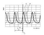
ここで、図3を参照して、EGR通路内ガス温度を推定する方法の具体例について説明する。図3は、横軸にクランク角(CA)を示し、縦軸に吸気圧(吸気管圧力)を示している。実線A1は、EGR装置20の暖機時(具体的にはEGR通路21やEGRクーラ23などが暖機している際を意味する。以下同じ。)における吸気圧の脈動を示している。破線A2は、EGR装置20の未暖機時(低温時)における吸気圧の脈動を示している。図示のように、未暖機時における吸気圧は、暖機時における吸気圧と比較して位相がずれている(遅れている)ことがわかる。これは、EGR装置20が低温である場合には圧力波の伝播が遅くなるからである。
Here, a specific example of a method for estimating the gas temperature in the EGR passage will be described with reference to FIG. FIG. 3 shows the crank angle (CA) on the horizontal axis and the intake pressure (intake pipe pressure) on the vertical axis. A solid line A1 indicates the pulsation of the intake pressure when the
したがって、本実施形態では、このような位相のずれに基づいて、EGR通路内ガス温度を推定する。具体的には、ECU50は、計測された吸気圧のピーク値が発生した時(以下、単に「吸気圧ピーク発生時」と呼ぶ。)のクランク角における位相と、EGR装置20の暖機時に得られる、吸気圧ピーク発生時のクランク角における位相に基づいて定めた所定値とを比較することで、EGR通路内ガス温度を推定する。
Therefore, in this embodiment, the gas temperature in the EGR passage is estimated based on such a phase shift. Specifically, the
一例としては、ECU50は、図3に示すように、計測された吸気圧ピーク発生時のクランク角について、各気筒10の基準位置C1(例えば上死点)からの変位量B2を求める。そして、ECU50は、この変位量B2と、EGR装置20の暖機時に得られる吸気圧ピーク発生時のクランク角に基づいて定めた所定値B1とを比較する(ここでは、暖機時における吸気圧ピーク発生時のクランク角についての基準位置C1からの変位量が、当該所定値B1に一致する場合を一例として図示している)。この場合、ECU50は、「B2<B1」であるため、EGR通路内ガス温度が低温であると判定する。即ち、EGRクーラ23が未暖機であると判定する。
As an example, as shown in FIG. 3, the
[制御処理]
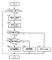
次に、図4を参照して、本実施形態に係る制御処理について説明する。図4は、本実施形態に係る制御処理を示すフローチャートである。この処理は、ECU50によって、所定の周期で繰り返し実行される。
[Control processing]
Next, a control process according to the present embodiment will be described with reference to FIG. FIG. 4 is a flowchart showing a control process according to the present embodiment. This process is repeatedly executed by the
まず、ステップS101では、ECU50は、EGRガスの導入中であるか否かを判定する。EGRガスの導入中である場合(ステップS101;Yes)、処理はステップS102に進み、EGRガスの導入中でない場合(ステップS101;No)、処理は終了する。
First, in step S101, the
ステップS102では、ECU50は、吸気圧センサ44及びクランク角センサ45の検出値に基づいて、吸気圧ピーク発生時のクランク角を計測する。そして、処理はステップS103に進む。
In step S102, the
ステップS103では、ECU50は、ステップS102で計測されたクランク角と、EGR装置20の暖機完了時におけるクランク角とを比較する。より具体的には、ECU50は、ステップS102で計測された吸気圧ピーク発生時のクランク角と、吸気圧ピーク発生時のクランク角に基づいて定めた所定値とを比較する。ここでは、計測された吸気圧ピーク発生時のクランク角における位相が、EGR装置20の暖機時に得られるような、吸気圧ピーク発生時のクランク角における位相から、所定以上ずれているか否かを判定する。そして、処理はステップS104に進む。
In step S103, the
ステップS104では、ECU50は、ステップS103における比較の結果、EGR通路内ガス温度が低温であるか否かを判定する、言い換えるとEGR配管低温状態であるか否かを判定する。例えば、ECU50は、ステップS102で計測された吸気圧ピーク発生時のクランク角についての各気筒10の基準位置(例えば上死点)からの変位量が、EGR装置20の暖機時に得られる吸気圧ピーク発生時のクランク角についての当該基準位置からの変位量に基づいて規定された所定値(予め設定される値)未満である場合、EGR通路内ガス温度が低温であると判定する。
In step S104, the
EGR通路内ガス温度が低温である場合(ステップS104;Yes)、処理はステップS105に進む。この場合には、EGRクーラ23が未暖機であるものと考えられる。これに対して、EGR通路内ガス温度が低温でない場合(ステップS104;No)、処理はステップS108に進む。この場合には、EGRクーラ23が暖機しており、且つEGR触媒22が活性状態であるものと考えられる。よって、ECU50は、通常のEGR制御を実行する(ステップS108)。そして、処理は終了する。
When the gas temperature in the EGR passage is low (step S104; Yes), the process proceeds to step S105. In this case, it is considered that the
ステップS105では、ECU50は、空燃比フィードバック補正量が所定値以下であるか否かを判定する。ここでは、ECU50は、空燃比フィードバック補正量が減量側にある程度大きいか否かを判定することで、EGR触媒22が未活性状態であるか否かを判定している。
In step S105, the
空燃比フィードバック補正量が所定値以下である場合(ステップS105;Yes)、処理はステップS106に進む。この場合には、EGR触媒22が未活性状態であるものと考えられる。よって、ECU50は、EGR触媒22の未活性状態でのEGRガス大量導入に起因する、吸気系へのデポジット導入を抑制すべく、EGRガス量を減少させる制御を行う(ステップS106)。具体的には、ECU50は、EGR弁33の開度を縮小する制御を行う。そして、処理は終了する。なお、上記のステップS106では、EGR触媒22が未活性状態である場合に、EGRガス量を減少させる制御のみを行う例を示したが、当該制御を行うと共に、EGRクーラ23への冷却水量を減少させる制御を行っても良い。
If the air-fuel ratio feedback correction amount is equal to or less than the predetermined value (step S105; Yes), the process proceeds to step S106. In this case, it is considered that the
これに対して、空燃比フィードバック補正量が所定値より大きい場合(ステップS105;No)、処理はステップS107に進む。この場合には、EGRクーラ23が未暖機であるものの、EGR触媒22は活性状態であるものと考えられる。よって、ECU50は、EGRクーラ23が未暖機状態でのすす堆積に起因する、EGRクーラ23の目詰まりを抑制すべく、EGRクーラ23への冷却水量を減少させる制御を行う(ステップS107)。具体的には、ECU50は、冷却水弁25を閉じる制御を行う。そして、処理は終了する。なお、ステップS105において上記したステップS106のようにEGRガス量を減少させる制御を行わないのは、この場合にはEGR触媒22は活性状態であるので、現在のEGR制御を継続することで、燃費の確保などを優先するためである。
On the other hand, when the air-fuel ratio feedback correction amount is larger than the predetermined value (step S105; No), the process proceeds to step S107. In this case, although the
以上説明した制御処理によれば、EGRクーラ23及びEGR触媒22のうちのいずれの能力が低下したかを適切に判別することができ、これに応じた制御を適切に実行することができる。したがって、吸気系のデポジット導入及びEGRクーラ23の目詰まりを効果的に抑制することが可能となる。
According to the control process described above, it is possible to appropriately determine which of the
[変形例]
上記では、ツインエントリターボ過給機を具備するシステムに本発明を適用する実施形態を示したが(図1及び図2参照)、本発明は、ツインエントリターボ過給機以外のターボ過給機を具備するシステムにも同様に適用することができる。
[Modification]
In the above, an embodiment in which the present invention is applied to a system including a twin entry turbocharger has been shown (see FIGS. 1 and 2). However, the present invention is not limited to a twin entry turbocharger. The present invention can be similarly applied to a system including the above.
3 吸気通路
4 排気通路
5 ターボ過給機
8 触媒
10 気筒
20 EGR装置
21 EGR通路
22 EGR触媒
23 EGRクーラ
24 冷却水通路
25 冷却水弁
33 EGR弁
43、44 吸気圧センサ
50 ECU
3
Claims (6)
前記EGR装置によってEGRガスを導入している際において、吸気圧においてピーク値が発生した際のクランク角における位相と、空燃比フィードバック制御における補正量とに基づいて、前記EGR触媒又は前記EGRクーラについての能力低下に対する判定を行う判定手段を備えることを特徴とする内燃機関の制御装置。 An internal combustion engine control device applied to an internal combustion engine including an EGR device having at least an EGR catalyst and an EGR cooler,
When the EGR gas is introduced by the EGR device, the EGR catalyst or the EGR cooler is determined based on the phase at the crank angle when the peak value is generated in the intake pressure and the correction amount in the air-fuel ratio feedback control. A control device for an internal combustion engine, comprising: a determination unit that performs a determination for a reduction in the performance of the internal combustion engine.
前記吸気圧においてピーク値が発生した際のクランク角における位相と、予め定めた基準となる位相とのずれに基づいて、前記EGR装置におけるEGR通路内のガス温度を推定すると共に、
前記空燃比フィードバック制御における補正量に基づいて、前記EGR触媒の状態を推定することで、前記判定を行う請求項1に記載の内燃機関の制御装置。 The determination means includes
Estimating the gas temperature in the EGR passage in the EGR device based on the difference between the phase at the crank angle when the peak value occurs in the intake pressure and the phase serving as a predetermined reference,
The control device for an internal combustion engine according to claim 1, wherein the determination is performed by estimating a state of the EGR catalyst based on a correction amount in the air-fuel ratio feedback control.
Priority Applications (1)
| Application Number | Priority Date | Filing Date | Title |
|---|---|---|---|
| JP2008321950A JP2010144597A (en) | 2008-12-18 | 2008-12-18 | Control device for internal combustion engine |
Applications Claiming Priority (1)
| Application Number | Priority Date | Filing Date | Title |
|---|---|---|---|
| JP2008321950A JP2010144597A (en) | 2008-12-18 | 2008-12-18 | Control device for internal combustion engine |
Publications (1)
| Publication Number | Publication Date |
|---|---|
| JP2010144597A true JP2010144597A (en) | 2010-07-01 |
Family
ID=42565285
Family Applications (1)
| Application Number | Title | Priority Date | Filing Date |
|---|---|---|---|
| JP2008321950A Pending JP2010144597A (en) | 2008-12-18 | 2008-12-18 | Control device for internal combustion engine |
Country Status (1)
| Country | Link |
|---|---|
| JP (1) | JP2010144597A (en) |
Cited By (3)
| Publication number | Priority date | Publication date | Assignee | Title |
|---|---|---|---|---|
| JP2012132337A (en) * | 2010-12-20 | 2012-07-12 | Toyota Motor Corp | Control device of internal combustion engine with supercharger |
| JP2013072293A (en) * | 2011-09-26 | 2013-04-22 | Daihatsu Motor Co Ltd | Control device for internal combustion engine |
| JP2017120029A (en) * | 2015-12-28 | 2017-07-06 | いすゞ自動車株式会社 | Internal combustion engine and control method thereof |
-
2008
- 2008-12-18 JP JP2008321950A patent/JP2010144597A/en active Pending
Cited By (3)
| Publication number | Priority date | Publication date | Assignee | Title |
|---|---|---|---|---|
| JP2012132337A (en) * | 2010-12-20 | 2012-07-12 | Toyota Motor Corp | Control device of internal combustion engine with supercharger |
| JP2013072293A (en) * | 2011-09-26 | 2013-04-22 | Daihatsu Motor Co Ltd | Control device for internal combustion engine |
| JP2017120029A (en) * | 2015-12-28 | 2017-07-06 | いすゞ自動車株式会社 | Internal combustion engine and control method thereof |
Similar Documents
| Publication | Publication Date | Title |
|---|---|---|
| JP5979173B2 (en) | Control device for internal combustion engine | |
| US7730718B2 (en) | Control system for internal combustion engine | |
| US8091347B2 (en) | Exhaust gas purification apparatus, internal combustion engine comprising the same, and particulate filter restoring method | |
| JP4253294B2 (en) | Engine self-diagnosis device | |
| US20090094963A1 (en) | Exhaust particulate matter measuring apparatus | |
| JP2008095542A (en) | Control device for internal combustion engine | |
| JP5146704B2 (en) | Engine system controller | |
| JP4670884B2 (en) | Exhaust gas recirculation device for internal combustion engine | |
| US7404291B2 (en) | Exhaust gas purifying apparatus for internal combustion engine | |
| JP2013007375A (en) | Fuel injection control apparatus for internal combustion engine | |
| EP3205865B1 (en) | Control device for vehicle | |
| JP6251143B2 (en) | Control device for spark ignition engine | |
| JP4267414B2 (en) | Catalyst control device for internal combustion engine | |
| JP4503498B2 (en) | Exhaust temperature sensor abnormality diagnosis device | |
| JP2010144597A (en) | Control device for internal combustion engine | |
| JP2011027058A (en) | Control device for internal combustion engine with supercharger | |
| JP5088306B2 (en) | Control device for internal combustion engine | |
| JP5608614B2 (en) | Engine EGR flow rate detection device | |
| JP6701786B2 (en) | Failure diagnosis method and failure diagnosis device | |
| JP4513779B2 (en) | Exhaust gas purification device for internal combustion engine | |
| JP2007332867A (en) | Control device for internal combustion engine | |
| JP4561656B2 (en) | Catalyst temperature estimation device for internal combustion engine | |
| JP2006242098A (en) | Exhaust emission control device for internal combustion engine | |
| JP4648274B2 (en) | Control device for internal combustion engine | |
| JP4686567B2 (en) | Exhaust purification device temperature control device |