JP2010143701A - Paper feeder - Google Patents
Paper feeder Download PDFInfo
- Publication number
- JP2010143701A JP2010143701A JP2008321902A JP2008321902A JP2010143701A JP 2010143701 A JP2010143701 A JP 2010143701A JP 2008321902 A JP2008321902 A JP 2008321902A JP 2008321902 A JP2008321902 A JP 2008321902A JP 2010143701 A JP2010143701 A JP 2010143701A
- Authority
- JP
- Japan
- Prior art keywords
- paper
- sheet
- stacking
- feeding device
- plate
- Prior art date
- Legal status (The legal status is an assumption and is not a legal conclusion. Google has not performed a legal analysis and makes no representation as to the accuracy of the status listed.)
- Pending
Links
- 230000001105 regulatory effect Effects 0.000 claims abstract description 55
- 238000003825 pressing Methods 0.000 claims abstract description 52
- 238000001514 detection method Methods 0.000 claims description 5
- 230000003028 elevating effect Effects 0.000 claims description 3
- 238000000034 method Methods 0.000 description 7
- 230000002265 prevention Effects 0.000 description 7
- 230000015572 biosynthetic process Effects 0.000 description 6
- 230000007246 mechanism Effects 0.000 description 6
- 238000004140 cleaning Methods 0.000 description 5
- 230000009467 reduction Effects 0.000 description 5
- 108091008695 photoreceptors Proteins 0.000 description 3
- 230000000903 blocking effect Effects 0.000 description 2
- 238000006243 chemical reaction Methods 0.000 description 2
- 230000008878 coupling Effects 0.000 description 2
- 238000010168 coupling process Methods 0.000 description 2
- 238000005859 coupling reaction Methods 0.000 description 2
- 238000012840 feeding operation Methods 0.000 description 2
- 238000010438 heat treatment Methods 0.000 description 2
- 230000001965 increasing effect Effects 0.000 description 2
- 230000000630 rising effect Effects 0.000 description 2
- 230000009471 action Effects 0.000 description 1
- 230000001174 ascending effect Effects 0.000 description 1
- QVQLCTNNEUAWMS-UHFFFAOYSA-N barium oxide Chemical compound [Ba]=O QVQLCTNNEUAWMS-UHFFFAOYSA-N 0.000 description 1
- 229910001864 baryta Inorganic materials 0.000 description 1
- 239000003086 colorant Substances 0.000 description 1
- 230000003472 neutralizing effect Effects 0.000 description 1
- 230000003287 optical effect Effects 0.000 description 1
- 230000008569 process Effects 0.000 description 1
- 230000004044 response Effects 0.000 description 1
- 238000000926 separation method Methods 0.000 description 1
- 239000000758 substrate Substances 0.000 description 1
- 230000007723 transport mechanism Effects 0.000 description 1
- 239000002699 waste material Substances 0.000 description 1
Images
Landscapes
- Sheets, Magazines, And Separation Thereof (AREA)
- Manual Feeding Of Sheets (AREA)
Abstract
Description
本発明は、画像形成装置に備えた用紙給紙装置、特に特殊な紙質の用紙を主として給紙する手差し用で小容量の用紙積載トレイ上の用紙を1枚ずつ給紙する用紙給紙装置に関する。
BACKGROUND OF THE
画像形成装置に用紙給紙装置を装着して用紙を給紙するとき、用紙給紙装置のサイド規制が十分でなく、用紙に曲がりが生じると画像が曲がって用紙上に作成され好ましくない。 When a sheet feeding device is mounted on the image forming apparatus to feed the sheet, the side regulation of the sheet feeding apparatus is not sufficient, and if the sheet is bent, the image is bent and formed on the sheet, which is not preferable.
通常、用紙給紙装置から供給される用紙は、用紙積載トレイ内に積載される用紙がサイド規制板によって幅方向が所要の位置と寸法に規制される。その幅規制は両サイドの規制板をラックとピニオンを介して所要の幅に移動させ、その位置と幅寸法が決められたら用紙を給紙して画像形成を開始するようにしている。また、決定したサイド規制板の位置を固定する為の手段として以下のようなものがあるがそれぞれに問題点がある。 Normally, the sheet fed from the sheet feeding device is regulated in a width direction to a required position and size by a side regulating plate for the sheet stacked in the sheet stacking tray. In the width regulation, the regulation plates on both sides are moved to a required width via a rack and a pinion, and when the position and the width dimension are determined, paper is fed to start image formation. Further, there are the following means for fixing the determined position of the side regulating plate, but each has a problem.
(1)サイド規制板の位置及び幅寸法が調整された段階でその調整状態が崩れないようにロックする方法が一般的に採られている。しかし、問題点としては、別の用紙を新しい位置と幅寸法にセットし直すときは、ロックの摘みを緩めながらスライドさせて適切な位置と幅寸法に調節し、調整の終わったところで再びロックするという方法が採られている。このような構成としていることにより操作上工数もかかり、かなり面倒な面がある。 (1) A method of locking so that the adjusted state does not collapse when the position and width dimension of the side regulating plate are adjusted is generally adopted. However, as a problem, when resetting another sheet to a new position and width dimension, loosen the knob of the lock and slide it to the appropriate position and width dimension, and then lock again when the adjustment is complete. The method is taken. With such a configuration, man-hours are required for operation, and there is a considerable trouble.
(2)また、特許文献1では、ラックとピニオンで用紙の位置と幅寸法に対応した調整をした後、ピニオンをブレーキ手段のパッドに接触させて、ピニオンの歯車を固定する方法が採られている。しかし、ラックのピニオンに対するバックラッシュのガタは依然として残る。それと共にピニオン歯車の固定はその側面を摩擦パッドで押さえるので、用紙積載トレイの用紙厚み方向の寸法が大きくなり、それに伴い不使用時に収納しておく収納スペースも大きくなる。この結果、必然的に画像形成装置の全体寸法が大きくなるという問題点がある。
(2) Further, in
(3)また、ピニオンだけでなくラックもロックする構成を採ることも考えられるが、構成は益々複雑になり好ましくない。そして(2)項のスペース増大の問題点は更に残る。 (3) Although it is conceivable to adopt a configuration in which not only the pinion but also the rack is locked, the configuration becomes more complicated, which is not preferable. And the problem of the space increase of the item (2) still remains.
特に手差しの用紙給紙装置の場合には、小容量の用紙ではあるが、用紙の幅規制精度は中容量や大容量のものと比較して劣るものであってはならない。しかも未使用時には折りたたんで画像形成装置の本体にコンパクトに収納されることが必要である。
本発明はこのような背景技術の欠点を解消して、用紙の幅寸法を簡単な手段で安定正確に規制すると共に、未使用時に画像形成装置本体に収容したときにも、画像形成装置本体を大きくすることなくコンパクトに収まるようにした用紙給紙装置及びそれを装着した画像形成装置を提供することを目的にする。 The present invention eliminates the disadvantages of the background art, regulates the width dimension of the paper stably and accurately with simple means, and also allows the image forming apparatus main body to be stored even when accommodated in the image forming apparatus main body when not in use. It is an object of the present invention to provide a paper feeding device that can be compactly accommodated without increasing the size, and an image forming apparatus equipped with the paper feeding device.
この目的は次の技術手段1から11の何れかによって達成される。
1.画像形成装置に設けられた用紙給紙装置であって、
筐体と、
該筐体に設けた用紙を積載する用紙積載台と、
該用紙積載台上の用紙の幅方向の位置と幅寸法を所定位置と所定長さに規制するべく該用紙積載台上を前記幅方向に移動可能に配設したサイド規制板と、
該サイド規制板よりも用紙の先端部側に設けられた該サイド規制板と共に前記幅方向に移動して用紙の幅方向端部を規制し、前記幅方向に平行な軸の周りに回動可能に軸支されたサイド規制補助部材と、
該サイド規制補助部材の下方に設けられ、積載された用紙の先端部の昇降動作を行う用紙積載昇降板と、
を有する用紙積載トレイと、
前記用紙積載昇降板を昇降駆動する駆動手段と、
回動した前記サイド規制補助部材の上部に接触させて該上部を押圧する押圧可動部材と、
前記用紙積載昇降板上の最上部の用紙を送り出す給紙ローラ部と、
を備え、
前記駆動手段により前記用紙積載昇降板を上昇させることにより、上方の前記サイド規制補助部材を回動させると共に、回動した該サイド規制補助部材を前記押圧可動部材と前記用紙積載昇降板により挟持する構成としたことを特徴とする用紙給紙装置。
2.前記サイド規制補助部材の上部に、用紙の浮き上がり防止用のガイド部材が設けられていることを特徴とする1に記載の用紙給紙装置。
3.前記ガイド部材の上面には弾性部材が設けられており、前記押圧可動部材の押圧部は前記弾性部材と接触することを特徴とする2に記載の用紙給紙装置。
4.前記サイド規制補助部材の下面には接触抵抗が高い摩擦部材が設けられていることを特徴とする1から3の何れか1項に記載の用紙給紙装置。
5.画像形成装置に設けられた用紙給紙装置であって、
筐体と、
該筐体に設けた揺動支軸の周りに回動して昇降する用紙を積載できる用紙積載昇降台と、
該用紙積載昇降台上の用紙の幅方向の位置と幅寸法を所定位置と所定長さに規制するべく該用紙積載昇降台上を前記幅方向に移動可能に配設したサイド規制板と、
を有する用紙積載トレイと、
前記用紙積載昇降台を昇降駆動する駆動手段と、
前記用紙積載昇降台と共に回動した前記サイド規制板の上部に接触させて該上部を押圧する押圧可動部材と、
前記用紙積載昇降台上の最上部の用紙を送り出す給紙ローラ部と、
を備え、
前記駆動手段により前記用紙積載昇降台を上昇させることにより、前記サイド規制板を前記押圧可動部材と前記用紙積載昇降台により挟持する構成としたことを特徴とする用紙給紙装置。
6.前記サイド規制板の上部に、用紙の浮き上がり防止用のガイド部材が設けられていることを特徴とする5に記載の用紙給紙装置。
7.前記ガイド部材の上面には弾性部材が設けられており、前記押圧可動部材の押圧部は前記弾性部材と接触することを特徴とする6に記載の用紙給紙装置。
8.前記サイド規制板の基台の下面には接触抵抗が高い摩擦部材が設けられていることを特徴とする5から7の何れか1項に記載の用紙給紙装置。
9.前記給紙ローラ部は、前記用紙積載昇降板又は前記用紙積載昇降台に積載された用紙の最上部に接して用紙の昇降に伴い揺動するピックアップローラを備え、
該ピックアップローラの位置を検出するセンサを有し、
該センサの検出信号に基づいて、前記用紙の最上部が所定位置を保持するように前記駆動手段を駆動制御することを特徴とする1から8の何れか1項に記載の用紙給紙装置。
10.前記用紙積載トレイは未使用時には回動させることにより前記画像形成装置の側部に収納可能であることを特徴とする1から9の何れか1項に記載の用紙給紙装置。
11.前記用紙積載トレイは手差し可能な用紙積載トレイであることを特徴とする1から10の何れか1項に記載の用紙給紙装置。
This object is achieved by any one of the following
1. A paper feeding device provided in the image forming apparatus,
A housing,
A paper stacking table for loading paper provided in the housing;
A side regulating plate disposed on the paper stacking base so as to be movable in the width direction so as to restrict the position and width dimension of the paper on the paper stacking base to a predetermined position and a predetermined length;
Moves in the width direction together with the side restricting plate provided on the front end side of the paper with respect to the side restricting plate, restricts the width direction end of the paper, and can rotate around an axis parallel to the width direction. A side regulation auxiliary member pivotally supported by
A sheet stacking lift plate provided below the side regulation assisting member and performing a lifting operation of the leading end of the stacked sheets;
A paper stacking tray having
Drive means for raising and lowering the paper stacking elevating plate;
A pressing movable member that contacts the upper part of the rotated side regulation auxiliary member and presses the upper part;
A paper feed roller unit for feeding the uppermost paper on the paper stacking lift plate;
With
By raising the sheet stacking lift plate by the driving means, the upper side regulation assisting member is rotated, and the rotated side regulation assisting member is sandwiched between the pressing movable member and the sheet stacking lifting plate. A paper feeding device characterized by having a configuration.
2. 2. The paper feeding apparatus according to 1, wherein a guide member for preventing the paper from floating is provided on the side regulation auxiliary member.
3. 3. The sheet feeding device according to 2, wherein an elastic member is provided on an upper surface of the guide member, and a pressing portion of the pressing movable member is in contact with the elastic member.
4). The sheet feeding device according to any one of
5). A paper feeding device provided in the image forming apparatus,
A housing,
A paper stacking platform capable of stacking a sheet that rotates up and down around a swing support shaft provided in the housing;
A side regulating plate disposed on the paper stacking platform so as to be movable in the width direction so as to regulate the position and width dimension of the paper on the paper stacking platform to a predetermined position and a predetermined length;
A paper stacking tray having
Drive means for raising and lowering the sheet stacking platform;
A pressing movable member that contacts and presses the upper part of the side regulating plate rotated together with the paper stacking lift;
A paper feed roller section for feeding the uppermost paper on the paper stacking platform;
With
The sheet feeding device according to
6). 6. The paper feeding apparatus according to 5, wherein a guide member for preventing the paper from lifting is provided on the side regulating plate.
7). The sheet feeding device according to claim 6, wherein an elastic member is provided on an upper surface of the guide member, and a pressing portion of the pressing movable member is in contact with the elastic member.
8). The sheet feeding device according to any one of 5 to 7, wherein a friction member having a high contact resistance is provided on a lower surface of the base of the side regulating plate.
9. The paper feed roller unit includes a pickup roller that is in contact with the top of the paper stacked on the paper stacking lift plate or the paper stacking lift and swings as the paper is lifted.
A sensor for detecting the position of the pickup roller;
9. The paper feeding apparatus according to any one of 1 to 8, wherein the driving unit is driven and controlled so that the uppermost part of the paper holds a predetermined position based on a detection signal of the sensor.
10. The sheet feeding device according to any one of 1 to 9, wherein the sheet stacking tray can be stored in a side portion of the image forming apparatus by rotating when the sheet stacking tray is not used.
11. The sheet feeding device according to any one of 1 to 10, wherein the sheet stacking tray is a manually loadable sheet stacking tray.
本発明により、用紙の幅寸法を簡単な手段で安定正確に規制すると共に、未使用時に画像形成装置本体に収容したときにも、画像形成装置本体を大きくすることなくコンパクトに収まるようにした用紙給紙装置及びそれを装着した画像形成装置が提供できるようになった。 According to the present invention, a paper sheet that can stably and accurately regulate the width dimension of a sheet by simple means, and can be stored compactly without enlarging the image forming apparatus body even when accommodated in the image forming apparatus body when not in use. A sheet feeding device and an image forming apparatus equipped with the sheet feeding device can be provided.
本発明の実施の形態例を図面に従って説明する。 Embodiments of the present invention will be described with reference to the drawings.
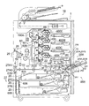
図1は、バライタ紙などの厚手の高級紙などを用紙として扱う手差しのできる用紙積載トレイを有する本発明の用紙給紙装置が装着され、更に従来通り普通紙を扱う中容量の用紙給紙カセットを内蔵した画像形成装置を示す正面断面図である。先ず該画像形成装置の概要について説明する。 FIG. 1 shows a medium-capacity paper feed cassette equipped with a paper feed device of the present invention having a paper stacking tray capable of manually feeding thick high grade paper such as baryta paper as paper, and handling ordinary paper as usual. FIG. First, an outline of the image forming apparatus will be described.
画像形成装置1は、中間転写ベルト50を有するタンデム形式のカラー画像形成装置である。
The
画像形成装置1は下部に内蔵される複数の用紙給紙カセット20を設けた給紙部を有し、更に画像形成装置1の側部に手差し用の用紙積載トレイ220Aを設けた本発明の用紙給紙装置200Aを有する。用紙給紙カセット20の上方には画像形成部40と中間転写ベルト50が設置されており、装置本体の上部には画像読取部30が設置されている。
The
また、両面原稿自動送り装置10の原稿給紙台aにセットされた原稿は、各種ローラによって画像読取部30に向けて搬送される。
Further, the original set on the original feeding table a of the double-sided
中容量の用紙給紙カセット20は、装置前面側(図1における紙面手前側)に引き出し可能となっている。複数の用紙給紙カセット20には白紙等の用紙がサイズによって分けられて500枚程度の容量ずつ収容されている。この内蔵された用紙給紙カセット20又は本発明の用紙給紙装置200A又は200Bにおける手差し用の用紙積載トレイ220A又は200Bに収容された用紙は給紙ローラ部21又は280によって1枚毎に給紙される。
The medium-capacity
画像形成部40は、Y、M、C、Kの各色のトナー像を形成するための4組の画像形成エンジン400Y、400M、400C及び400Kを有している。画像形成エンジン400Y、400M、400C、400Kは、この順で上から下方向に直線状に配列されており、各々同じ構成となっている。
The image forming unit 40 includes four sets of
イエロー色用の画像形成エンジン400Yを例にとって構成を説明すると、画像形成エンジン400Yは反時計方向に回転する感光体410、帯電部420、露光部430、現像部440、クリーニング部450を有する。クリーニング部450は、感光体410の最下部に対向した領域を含んで配置されている。
The configuration of the
装置本体の中央部に位置する中間転写ベルト50は無端状であり、所定の体積抵抗率を有する。一次転写ローラ(転写部)510は、中間転写ベルト50を挟んで感光体410と対向する位置に設置されている。
The
次に画像形成装置1において、カラー画像を形成する動作を説明する。
Next, an operation for forming a color image in the
感光体410は、駆動モータ(図示せず)により回転駆動され、帯電部420の放電により負極性に帯電される(例えば−800V)。次に、露光部430により感光体410上に画像情報に応じた光書込がなされて静電潜像が形成される。形成された静電潜像が現像部440を通過すると、現像部内で負極性に帯電されたトナーが負極性現像バイアスの印加により潜像画像の部分に付着し、感光体410上にトナー像が形成される。形成されたトナー像は、感光体410に圧着する中間転写ベルト50へ転写される。転写後に感光体410上に残留したトナーはクリーニング部450により清掃される。
The
画像形成エンジン400Y、400M、400C及び400K各々で形成されたトナー像が中間転写ベルト50に各一次転写ローラ510によって重畳して転写される。これにより、中間転写ベルト50上にカラー画像が形成される。用紙は用紙給紙カセッテ20又は手差し用の本発明の前記用紙積載トレイ220により1枚ずつ給紙され、共通の搬送路22にあるレジストローラ60の位置まで搬送される。レジストローラ60に用紙が突き当てられて一旦停止し、搬送中の用紙の曲がりが矯正されてから、用紙は中間転写ベルト50上のトナー像と画像位置が一致するタイミングでレジストローラ60より給送される。
The toner images formed by the
レジストローラ60により給送された用紙は、ガイド板により案内され、中間転写ベルト50及び二次転写ローラ70により形成された転写ニップ位置へ送り込まれる。二次転写ローラ70により構成される転写ニップ位置では用紙を中間転写ベルト50側へ押圧している。トナーと逆極性のバイアス(例えば+500V)が転写部70に印加されることにより、静電気力の作用で、中間転写ベルト50上のトナー像が用紙へ転写される。用紙は、除電針からなる分離装置(図示せず)により除電されて中間転写ベルト50から分離され、加熱ローラ、加圧ローラのローラ対又は、加熱ベルト、加圧ローラからなる定着部80へ送られる。その結果、トナー像が用紙へ定着され、画像形成された用紙が装置外の排紙トレイ25へ排出される。
The sheet fed by the
以上は記録媒体としての用紙の片側である第1面への画像形成を行う状態を説明したものであるが、両面複写の場合は、排紙切換部材26が切り替わり、用紙案内部26Aが開放され、用紙は破線矢印の方向に搬送される。
The above describes the state in which image formation is performed on the first side, which is one side of a sheet as a recording medium. However, in the case of duplex copying, the sheet
更に、搬送機構27A1、27A2により用紙は下方の搬送路27Bに搬送され、給紙搬送装置27の特に給紙反転部を形成するローラ対27Cによりスイッチバックさせられ、分岐部27Dで搬送路を切り換え、今までの用紙の後端部は先端部となって両面複写用給紙ユニット130内に搬送される。
Further, the paper is transported to the
用紙は両面複写用給紙ユニット130に設けられた搬送ガイド131の中を給紙方向に移動し、給紙ローラ132で用紙は再給紙され、前記搬送路22に案内される。
The sheet moves in the sheet feeding direction in the
そして再び、上述したように二次転写ローラ70の方向に用紙が搬送され、用紙の裏面である第2面にトナー画像を転写し、定着装置80で定着した後、排紙トレイ25上に排紙する。
Then, as described above, the sheet is conveyed in the direction of the
また、二次転写ローラ70により用紙上にカラー画像が転写された後、用紙を曲率分離した中間転写ベルト50は、中間転写ベルトのクリーニング部190Aにより残留トナーが除去される。
Further, after the color image is transferred onto the sheet by the
なお、本実施形態における画像形成装置1は電子写真方式により用紙にカラー画像を形成するものであるが、本発明に係る画像形成装置は本実施形態に限定されるものではなく、モノクロ画像を形成する画像形成装置であっても構わない。
The
さて、このような画像が作成される過程において、各感光体410や中間転写ベルト50上の残留トナーは各クリーニング部450、190Aに回収された後、スパイラル部材を内部に設けたパイプ605内を搬送され、廃トナーボックス600に送り込まれる。
In the process of creating such an image, residual toner on each photoconductor 410 and
第1の実施形態例
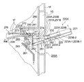
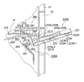
次に、画像形成装置1の給紙可能位置に用紙積載トレイ220Aをセットした本発明の第1の実施形態例としての用紙給紙装置200Aについて、図1と、図1における本発明の用紙給紙装置200Aの部分の拡大図である図2と、その平面図である図3を用いて詳細に説明する。
First Embodiment Next, a
即ち、画像形成装置1に設けられる、例えば厚手の特殊な高級紙を給紙対象とし、手差し給紙ができる本発明の第1の実施形態例の用紙給紙装置200Aでは、筐体221の中に次の(1)〜(3)に示す各機構が組み込まれた用紙積載トレイ220Aが備えられている。そして該用紙積載トレイ220Aは画像形成装置1の本体側部の収納スペース1Gから回動軸221Rの周りに回動して、用紙を給紙できる状態に画像形成装置1にセット可能にしてある。尚、筐体221の用紙給紙方向端部には、用紙の先端位置決めの為の用紙突き当て部221Sが設けられている。
That is, in the
(1)用紙を積載する用紙積載台222と、該用紙積載台222上の用紙の幅方向の位置と幅寸法を所定位置と所定長さに規制するべく該用紙積載台222上を前記幅方向に移動可能に配設したサイド規制板223A、223B。
(1) A sheet loading table 222 for loading sheets, and the width direction on the sheet loading table 222 so as to regulate the position and width dimension of the sheet on the sheet loading table 222 to a predetermined position and a predetermined length.
(2)該サイド規制板223A、223Bの先端部の前記幅方向に平行な軸の周りに回動可能に軸支されたサイド規制補助部材231A、231B。
(2) Side
(3)該サイド規制補助部材231A、231Bの下方に設けられ、積載された用紙の先端部の昇降動作を行う用紙積載昇降板251。該用紙積載昇降板251は、前記用紙積載台222の用紙給紙方向先頭部に隣接して、前記筐体222の前記幅方向に平行な軸の周りに回動可能に軸支され、積載された用紙の先端部の昇降動作が行える構造にしてある。
(3) A sheet stacking
前記サイド規制板223A、223Bはその用紙規制面に直角に形成された基板223A−1、223B−1が前記用紙積載台222を挟んで下部のラック板223A−2、223B−2と段付きピン227で前記用紙積載台222の厚さに相当する間隔で結合されている。そして前記用紙積載台222には用紙の幅方向に長孔226が設けられ、前記段付きピン227がスライド可能に嵌合されている。また、前記ラック板223A−2、223B−2は筐体221の底部に設けられたピニオン225と噛合している。
The
このようにして、前記サイド規制板223A、223Bを幅方向に動かすことによって、また、スケール目盛229に照合させることも併用して、前記サイド規制板223A、223Bが供給される用紙の所要幅と位置に適合するように規制してセットされる。このようにラックとピニオン構造によって、サイド規制板223A,223Bは幅方向を同じ移動量で移動することができるので、中央基準で幅調整をすることができる。尚、片側基準の場合は、サイド規制板は一方を固定し他方のみを幅方向に移動させる方式を採れば良い。
In this way, by moving the
更に、本発明の第1の実施形態例としての用紙給紙装置200Aでは、画像形成装置1の内部の基体フレーム1Fに、前記用紙積載昇降板251を昇降駆動する駆動手段260と、前記サイド規制補助部材231A、231Bの上部に接触させて該上部を押圧部274で押圧する押圧可動部材271と、が設けられている。そして前記用紙積載昇降板251上の最上部の用紙を1枚ずつ送り出す給紙ローラ部280が備えられている。
Further, in the
前記用紙積載昇降板251の昇降は、画像形成装置1の前記基体フレーム1Fに設置された駆動手段260即ち、減速モータ263の減速軸261に回動可能に連結された持ち上げレバー262を駆動することによって行われる。該持ち上げレバー262の先端部を前記用紙積載昇降板251の端部の下部に接触させ減速モータ263の1方向の回転により上昇し他の方向の回転により下降するようにして前記用紙積載昇降板251の昇降がなされる。
The lifting / lowering of the paper stacking lifting / lowering
基体フレーム1Fに設けた回動軸272Sの周りに回動し、一方の端部に前記サイド規制補助部材231A、231Bの上部に接触して押圧する押圧部274を有し、他方の端部にバネ掛け部275を有する回動ブラケット272を備えた押圧可動部材271が設けられている。そして前記バネ掛け部275と前記基体フレーム1Fに設けたバネ掛け部276との間に掛けられたバネ273によって前記押圧部274が前記サイド規制補助部材231A、231Bの上部を押圧可能に付勢する。
There is a
押圧可動部材271の回動ブラケット272は不図示のストッパにより所定範囲で回動可能である。用紙積載昇降板251の上昇に伴い、その上方に載せてあるサイド規制補助部材231A、231Bが回動(図示時計方向)する。当該回動に伴い、上方にある押圧部274がサイド規制補助部材231A、231Bの上面に接触してバネ力により上昇に抗う押圧力を付与する。つまり用紙積載昇降板251の上昇動作により、上方のサイド規制補助部材231A、231Bを回動させると共に、回動したサイド規制補助部材231A、231Bを押圧部274と用紙積載昇降板251により挟持する構成としている。
The
なお、サイド規制補助部材231A、231Bが下方に待機している状態(図2の実線図の状態)においては、押圧可動部材271がサイド規制補助部材231A、231Bの上面に接触していないので、サイド規制補助部材231A、231B及びこれに連結しているサイド規制板223A、223Bの幅方向への移動を自由に行うことができる。
In the state where the side regulation
そして前記サイド規制補助部材231A、231Bには用紙の浮き上がり防止用のガイド部材233A、233Bが設けられていて、その上面は前記押圧部274が接触する前記サイド規制補助部材231A、231Bの上部を形成している。寸法的に前記ガイド部材233A、233Bの上面は、用紙幅方向に前記サイド規制補助部材231A、231Bがサイズ変換のために幅方向に移動しても前記押圧部274が常に接触して押圧可能になっている。また、前記ガイド部材233A、233Bの上面には、弾性部材を固定して設けておくことが好ましい。
The side
また、給紙位置にはピックアップローラ281と重送防止ローラ282と該重送防止ローラ282に対してローラ対を形成する搬送ローラ283とから成る給紙ローラ部280が設けられていて、用紙積載昇降板251上の用紙を最上部のものから順次1枚ずつ給紙する。そして給紙された用紙は本発明の第1の実施形態例である用紙給紙装置200A及び後述する第2の実施形態例である用紙給紙装置200B専用の搬送路22Hを通り、共通の前記搬送路22に合流して転写部70で画像が転写され定着部80で定着されて排紙トレイ25に回収される。
The paper feed position is provided with a paper
尚、重送防止ローラ282はピックアップローラ281で2枚以上の用紙が誤って搬送されるときは余分の用紙は堰き止めたり戻したりする役目を持つ。
The double
一方、用紙の補給により、前記用紙積載台222及びそれに続く前記用紙積載昇降板251に載せられた複数枚の用紙の先端部は画像形成に待機させるように前記駆動手段260によって前記用紙積載昇降板251が給紙の所定位置に達するまで上昇し始める。そして最上部の用紙が給紙ローラ部280に給紙可能な位置まで上昇して停止した後、画像形成に対応して用紙の1枚ずつの給紙が開始される。
On the other hand, when the paper is replenished, the sheet stacking lift plate is moved by the driving means 260 so that the leading ends of the plurality of sheets placed on the
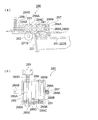
次に、この給紙ローラ部280の構成と最上部の用紙の検知機構について図4(a)、(b)を用いて説明する。
Next, the configuration of the paper
図4(a)は給紙ローラ部の構成と、該給紙ローラ部に設けた用紙積載昇降板251の最上部の用紙位置を検知する機構を示す正面図であり、(b)はその平面図である。
4A is a front view showing the configuration of the paper feed roller unit and a mechanism for detecting the uppermost paper position of the paper stacking
搬送ローラ283とピックアップローラ281とはそれぞれ同心のシャフト285A、285Bに一体に固定されて該シャフト285A、285Bはブラケット284に軸受けを介して回転可能に軸支されている。また搬送ローラ283には歯車286Aが、ピックアップローラ281には歯車286Bが同心に固定されている。そして、両歯車286A、286Bの中間部にはアイドルの歯車286Cがブラケット284に植えられたピン285C上に回転可能に軸支されて、前記3つの歯車は噛合して歯車列が形成される。
The
また、シャフト285Aの一端はカップリング285Dを介して、基体フレーム1Fに固定したモータ285に直結されている。そしてシャフト285Aの他端は同じく基体フレーム1Fに固定した軸受け285Eに回転可能に軸支されている。また、ブラケット284はシャフト285Aの周りに揺動可能にしてあり、揺動軸に対してブラケット284の一方の端部にアクチュエータ284Aが設けられ、他方の端部にはバネ掛け部284Bが設けられていて基体フレーム1Fとの間にバネ289が掛けられている。これによって前記ピックアップローラ281が前記用紙積載昇降板251上の用紙を押圧するように付勢される。またその揺動範囲が不必要に大きくならないようにストッパ284Sが設けられている。前記アクチュエータ284Aが基体フレーム1Fに固定された保持器287に設けた投光素子288A及び受光素子288Bよりなるセンサ288の光線を遮断又は通過させることを検出して揺動するピックアップローラ281の位置を検出する。当該検出値により前記用紙積載昇降板251上、及び後述する用紙給紙装置200Bの用紙積載昇降台222B上の最上部の用紙の最適範囲の位置が検出できる。
One end of the
この検出信号によって前記用紙積載昇降板251の昇降を駆動する前記減速モータ263を駆動させ持ち上げレバー262を回動させて用紙積載昇降板251上、及び後述する用紙給紙装置200Bの用紙積載昇降台222B上の最上部にある用紙の位置を正確に決めながら給紙して行くことが可能になる。
In response to this detection signal, the
また、前記押圧可動部材271の押圧部274は、サイド規制補助部材231A、231Bに取り付けられた前記ガイド部材233A、233Bを介してサイド規制補助部材231A、231Bの下部が用紙積載昇降板251を押圧する。つまり回動したサイド規制補助部材231A、231Bを押圧可動部材271と用紙積載昇降板251により挟持する。このことによりサイド規制補助部材231A、231Bをロックすることができる。
The
それと共にサイド規制補助部材231A、231Bの回動軸232を介してサイド規制板223A、223Bが用紙積載台222にロックされる。尚、サイド規制補助部材231A、231Bの下面には摩擦抵抗の高い摩擦部材が固定されている。したがって、給紙稼働中に用紙の幅方向のサイド規制が崩れることがなく、正確で安定した用紙の幅規制が維持される。
At the same time, the
用紙がなくなるのが別のセンサ(図示せず)で検出されると、用紙積載昇降板251は持ち上げレバー262が駆動手段260によって用紙の補給位置まで下降して、用紙積載台222上に必要な量の用紙が積載補給される。そのとき用紙の先端部が前記用紙積載昇降板251に十分掛かった状態で積載される。
When it is detected by another sensor (not shown) that the sheet runs out, the sheet
また用紙給紙装置200Aの給紙を終了した用紙積載トレイ220Aを画像形成装置1の側部に収納したいときは、駆動手段260の減速モータ263によって持ち上げレバー262を更に図1、図2に示すように退避位置まで下げておく。このような状態にして、用紙積載トレイ220の筐体221をその回動軸221Rを中心に回動させて画像形成装置1の側部の一部の内側に設けた収納スペース1Gに格納しておくことができる。
Further, when it is desired to store the
また、用紙積載トレイ220Aが給紙位置にセットされているときは、その状態でロックし続けられるようにストッパ221Tが設けられている。以上、本発明の第1の実施の形態例である用紙給紙装置200Aについて詳細に説明した。
Further, when the
第2の実施形態例
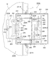
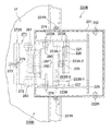
次に第2の実施の形態例について述べる。画像形成装置1の給紙可能位置に用紙積載トレイ220Bをセットした第2の実施形態例としての用紙給紙装置200Bの部分正面断面図である図5及びその平面図である図6を用いて詳細に説明する。
Second Embodiment Next, a second embodiment will be described. FIG. 5 which is a partial front sectional view of a
画像形成装置1に設けられる、例えば厚手の特殊な高級紙を給紙対象とし、手差し給紙ができる本発明の第2の実施形態例である用紙給紙装置200Bでは、筐体221の中に次のような各機構が組み込まれた用紙積載トレイ220Bが備えられている。即ち、該用紙積載トレイ220Bは画像形成装置1の本体側部の収納スペース1Gから回動軸221Rの周りに回動して、用紙を給紙できる状態に画像形成装置1にセット可能にしてある。そして、筐体221の用紙給紙方向端部には、用紙の先端位置決めの為の用紙突き当て部221Sが設けられている。
In the
また、用紙を積載して筐体221に設けた揺動支軸222Rの周りに回動して昇降する用紙積載昇降台222Bと、該用紙積載昇降台222B上の用紙の幅方向の位置と幅寸法を所定位置と所定長さに規制するべく該用紙積載昇降台222B上を前記幅方向に移動可能に配設したサイド規制板223A、223Bとが設けられている。
Also, a
前記サイド規制板223A、223Bはその用紙規制面に直角に形成された基板223A−1、223B−1が前記用紙積載昇降台222Bを挟んで下部のラック板223A−2、223B−2と段付きピン227で前記用紙積載昇降台222Bの厚さに相当する間隔で結合されている。そして前記用紙積載昇降台222Bには用紙の幅方向に長孔226が設けられ、前記段付きピン227がスライド可能に嵌合されている。また、前記ラック板223A−2、223B−2は用紙積載昇降台222Bの下部に設けられたピニオン225と噛合している。
The
このようにして、前記サイド規制板223A、223Bを幅方向に動かすことによって、また、スケール目盛229に照合させることも併用して、前記サイド規制板223A、223Bが供給される用紙の所要幅と位置に適合するように規制してセットされる。このラックとピニオン構造によって、サイド規制板223A,223Bは幅方向を同じ移動量で移動することができるので、中央基準で幅調整をすることができる。尚、片側基準の場合は、サイド規制板は一方を固定し他方のみを幅方向に移動させる方式を採れば良い。
In this way, by moving the
このように、第2の実施形態例はその用紙積載トレイ220Bの構造が第1の実施形態例の用紙積載トレイ220Aの構造とはかなり異なる構造となる。
Thus, the structure of the
第2の実施形態例の用紙給紙装置200Bでは、画像形成装置1の内部の基体フレーム1Fに、前記用紙積載昇降台222Bを昇降駆動する駆動手段260と、前記サイド規制板223A、223Bの上部に接触させて該上部を押圧部274で押圧する押圧可動部材271と、が設けられている。そして前記用紙積載昇降台222B上の最上部の用紙を1枚ずつ送り出す給紙ローラ部280が備えられている。これらの構造については第1,第2両実施形態例ともほぼ同じ構造にしてある。しかし、これらのこうぞうが前記用紙積載トレイ220B、220Aに対する係わり方がそれぞれ異なるので、第2の実施の形態例についても、以下に詳しく説明する。
In the
前記用紙積載昇降台222Bの昇降は、画像形成装置1の前記基体フレーム1Fに設置された駆動手段260即ち、減速モータ263の減速軸261に回動可能に連結された持ち上げレバー262を駆動することによって行われる。該持ち上げレバー262の先端部を前記用紙積載昇降台222Bの端部の下部に接触させ減速モータ263の1方向の回転により上昇し他の方向の回転により下降するようにして前記用紙積載昇降台222Bの昇降がなされる。
The raising / lowering of the
基体フレーム1Fに設けた回動軸272Sの周りに回動し、一方の端部に前記サイド規制板223A、223Bの上部に接触して押圧する押圧部274を有し、他方の端部にバネ掛け部275を有する回動ブラケット272を備えた押圧可動部材271が設けられている。そして前記バネ掛け部275と前記基体フレーム1Fに設けたバネ掛け部276との間に掛けられたバネ273によって前記押圧部274が前記サイド規制板223A、223Bの上部を押圧可能に付勢する。
There is a
押圧可動部材271の回動ブラケット272は不図示のストッパにより所定範囲で回動可能である。用紙積載昇降台222Bの上昇に伴い、その上に幅方向にスライド可能に設けられたサイド規制板223A、223Bも上昇する。この上昇に伴い、上方にある押圧部274がサイド規制板223A、223Bの上面に接触してバネ力により上昇に抗う押圧力を付与する。つまり用紙積載昇降台222Bの上昇動作により、用紙積載昇降台222B上に設けられたサイド規制板223A、223Bも共に回動して上昇し、上昇したサイド規制板223A、223Bを押圧部274と用紙積載昇降台222Bにより挟持する構成としている。
The
なお、サイド規制板223A、223Bが下方に待機している状態(図5の実線図の状態)においては、押圧可動部材271がサイド規制板223A、223Bの上面に接触していないので、サイド規制板223A、223Bの幅方向への移動を手動で自由に行うことができる。
In the state where the
そして前記サイド規制板223A、223Bには用紙の浮き上がり防止用のガイド部材233A、233Bが設けられていて、その上面は前記押圧部274が接触する前記サイド規制板223A、223Bの上部を形成している。寸法的に前記ガイド部材233A、233Bの上面は、用紙幅方向に前記サイド規制板223A、223Bがサイズ変換のために幅方向に移動しても前記押圧部274が常に接触して押圧可能になっている。また、前記ガイド部材233A、233Bの上面には、弾性部材を固定して設けておくことが好ましい。
The
また、給紙位置にはピックアップローラ281と重送防止ローラ282と該重送防止ローラ282に対してローラ対を形成する搬送ローラ283とから成る給紙ローラ部280が設けられていて、用紙積載昇降台222B上の用紙を最上部のものから順次1枚ずつ給紙する。そして給紙された用紙は本発明の用紙給紙装置200A又は200B専用の搬送路22Hを通り、共通の前記搬送路22に合流して転写部70で画像が転写され定着部80で定着されて排紙トレイ25に回収される。
The paper feed position is provided with a paper
尚、重送防止ローラ282はピックアップローラ281で2枚以上の用紙が誤って搬送されるときは余分の用紙は堰き止めたり戻したりする役目を持つ。
The double
一方、用紙の補給により、前記用紙積載台222Bに載せられた複数枚の用紙の先端部は画像形成に待機させるように前記駆動手段260によって前記用紙積載昇降台222Bが給紙の所定位置に達するまで上昇し始める。そして最上部の用紙が給紙ローラ部280に給紙可能な位置まで上昇して停止した後、画像形成に対応して用紙の1枚ずつの給紙が開始される。
On the other hand, when the paper is replenished, the driving
次に、この給紙ローラ部280の構成と最上部の用紙の検知機構は、図4(a)、(b)に示されるようになる。これは第1の実施形態例である用紙給紙装置200A、第2の実施形態例である用紙給紙装置200Bの何れにも全く共通するものであり、既に第1の実施形態例の用紙給紙装置200Aの説明で記述したので、これ以上の説明は省略する。
Next, the configuration of the paper
また、前記押圧可動部材271の押圧部274は、サイド規制板223A、223Bに取り付けられた前記ガイド部材233A、233Bを押圧し、これによって、サイド規制板223A、223Bの下部が用紙積載昇降台222Bを押圧する。つまり回動して上昇したサイド規制板補助部材223A、223Bを押圧可動部材271と用紙積載昇降台222Bにより挟持する。
Further, the
これにより、サイド規制板223A、223Bが用紙積載昇降台222Bにロックされる。尚、サイド規制板223A、223Bの基台223A−1、223B−1の下面には摩擦抵抗の高い摩擦部材が用いられることが好ましい。このようにして、給紙稼働中に用紙の幅方向のサイド規制が崩れることがなく、正確で安定した用紙の幅規制が維持される。
As a result, the
用紙がなくなるのが別のセンサ(図示せず)で検出されると、用紙積載昇降台222Bは持ち上げレバー262が駆動手段260によって用紙の補給位置まで下降して、用紙積載昇降台222B上に必要な量の用紙がその先端部を突き当て部221Sに揃えられて積載補給される。
When it is detected by another sensor (not shown) that the sheet runs out, the
また用紙給紙装置200Bの給紙を終了した用紙積載トレイ220Bを画像形成装置1の側部に収納したいときは、駆動手段260の減速モータ263によって持ち上げレバー262を更に図1に示すように退避位置まで下げておく。このような状態にして、用紙積載トレイ220Bの筐体221をその回動軸221Rを中心に回動させて画像形成装置1の側部の一部の内側に設けた収納スペース1Gに格納しておくことができる。
When it is desired to store the
また、用紙積載トレイ220Bが給紙位置にセットされているときは、その状態でロックし続けられるようにストッパ221Tが設けられている。
Further, when the
1 画像形成装置
1F 基体フレーム
1G 収納スペース
200A,200B 用紙給紙装置
220A,220B 用紙積載トレイ
221 筐体
221T ストッパ
221R 回動軸
222 用紙積載台
222B 用紙積載昇降台
223A,223B サイド規制板
223A−1,223B−1 基台
223A−2,223B−2 ラック
225 ピニオン
227 段付きピン
231A,231B サイド規制補助部材
232 回動軸
233A,233B ガイド部材
251 用紙積載昇降板
252 回動軸
260 駆動手段
262 持ち上げレバー
263 減速モータ
271 押圧可動部材
272 回動ブラケット
272S 回動軸
273,289 バネ
274 押圧部
280 給紙ローラ
281 ピックアップローラ
282 重送防止ローラ
283 搬送ローラ
284 ブラケット
284A アクチュエータ
285A,285B シャフト
285C ピン
285D カップリング
286A,286B,286C 歯車
287 保持器
288 センサ
DESCRIPTION OF
Claims (11)
筐体と、
該筐体に設けた用紙を積載する用紙積載台と、
該用紙積載台上の用紙の幅方向の位置と幅寸法を所定位置と所定長さに規制するべく該用紙積載台上を前記幅方向に移動可能に配設したサイド規制板と、
該サイド規制板よりも用紙の先端部側に設けられた該サイド規制板と共に前記幅方向に移動して用紙の幅方向端部を規制し、前記幅方向に平行な軸の周りに回動可能に軸支されたサイド規制補助部材と、
該サイド規制補助部材の下方に設けられ、積載された用紙の先端部の昇降動作を行う用紙積載昇降板と、
を有する用紙積載トレイと、
前記用紙積載昇降板を昇降駆動する駆動手段と、
回動した前記サイド規制補助部材の上部に接触させて該上部を押圧する押圧可動部材と、
前記用紙積載昇降板上の最上部の用紙を送り出す給紙ローラ部と、
を備え、
前記駆動手段により前記用紙積載昇降板を上昇させることにより、上方の前記サイド規制補助部材を回動させると共に、回動した該サイド規制補助部材を前記押圧可動部材と前記用紙積載昇降板により挟持する構成としたことを特徴とする用紙給紙装置。 A paper feeding device provided in the image forming apparatus,
A housing,
A paper stacking table for loading paper provided in the housing;
A side regulating plate disposed on the paper stacking base so as to be movable in the width direction so as to restrict the position and width dimension of the paper on the paper stacking base to a predetermined position and a predetermined length;
Moves in the width direction together with the side restricting plate provided on the front end side of the paper with respect to the side restricting plate, restricts the width direction end of the paper, and can rotate around an axis parallel to the width direction. A side regulation auxiliary member pivotally supported by
A sheet stacking lift plate provided below the side regulation assisting member and performing a lifting operation of the leading end of the stacked sheets;
A paper stacking tray having
Drive means for raising and lowering the paper stacking elevating plate;
A pressing movable member that contacts the upper part of the rotated side regulation auxiliary member and presses the upper part;
A paper feed roller unit for feeding the uppermost paper on the paper stacking lift plate;
With
By raising the sheet stacking lift plate by the driving means, the upper side regulation assisting member is rotated, and the rotated side regulation assisting member is sandwiched between the pressing movable member and the sheet stacking lifting plate. A paper feeding device characterized by having a configuration.
筐体と、
該筐体に設けた揺動支軸の周りに回動して昇降する用紙を積載できる用紙積載昇降台と、
該用紙積載昇降台上の用紙の幅方向の位置と幅寸法を所定位置と所定長さに規制するべく該用紙積載昇降台上を前記幅方向に移動可能に配設したサイド規制板と、
を有する用紙積載トレイと、
前記用紙積載昇降台を昇降駆動する駆動手段と、
前記用紙積載昇降台と共に回動した前記サイド規制板の上部に接触させて該上部を押圧する押圧可動部材と、
前記用紙積載昇降台上の最上部の用紙を送り出す給紙ローラ部と、
を備え、
前記駆動手段により前記用紙積載昇降台を上昇させることにより、前記サイド規制板を前記押圧可動部材と前記用紙積載昇降台により挟持する構成としたことを特徴とする用紙給紙装置。 A paper feeding device provided in the image forming apparatus,
A housing,
A paper stacking platform capable of stacking a sheet that rotates up and down around a swing support shaft provided in the housing;
A side regulating plate disposed on the paper stacking platform so as to be movable in the width direction so as to regulate the position and width dimension of the paper on the paper stacking platform to a predetermined position and a predetermined length;
A paper stacking tray having
Drive means for raising and lowering the sheet stacking platform;
A pressing movable member that contacts and presses the upper part of the side regulating plate rotated together with the paper stacking lift;
A paper feed roller section for feeding the uppermost paper on the paper stacking platform;
With
The sheet feeding device according to claim 1, wherein the side regulating plate is sandwiched between the pressing movable member and the sheet stacking platform by raising the sheet stacking platform by the driving means.
該ピックアップローラの位置を検出するセンサを有し、
該センサの検出信号に基づいて、前記用紙の最上部が所定位置を保持するように前記駆動手段を駆動制御することを特徴とする請求項1から8の何れか1項に記載の用紙給紙装置。 The paper feed roller unit includes a pickup roller that is in contact with the top of the paper stacked on the paper stacking lift plate or the paper stacking lift and swings as the paper is raised and lowered,
A sensor for detecting the position of the pickup roller;
9. The paper feed according to claim 1, wherein the driving unit is driven and controlled so that the uppermost part of the paper holds a predetermined position based on a detection signal of the sensor. apparatus.
Priority Applications (1)
| Application Number | Priority Date | Filing Date | Title |
|---|---|---|---|
| JP2008321902A JP2010143701A (en) | 2008-12-18 | 2008-12-18 | Paper feeder |
Applications Claiming Priority (1)
| Application Number | Priority Date | Filing Date | Title |
|---|---|---|---|
| JP2008321902A JP2010143701A (en) | 2008-12-18 | 2008-12-18 | Paper feeder |
Publications (1)
| Publication Number | Publication Date |
|---|---|
| JP2010143701A true JP2010143701A (en) | 2010-07-01 |
Family
ID=42564530
Family Applications (1)
| Application Number | Title | Priority Date | Filing Date |
|---|---|---|---|
| JP2008321902A Pending JP2010143701A (en) | 2008-12-18 | 2008-12-18 | Paper feeder |
Country Status (1)
| Country | Link |
|---|---|
| JP (1) | JP2010143701A (en) |
Cited By (1)
| Publication number | Priority date | Publication date | Assignee | Title |
|---|---|---|---|---|
| US9796541B2 (en) | 2015-02-25 | 2017-10-24 | Konica Minolta, Inc. | Sheet feeder and image forming apparatus |
-
2008
- 2008-12-18 JP JP2008321902A patent/JP2010143701A/en active Pending
Cited By (1)
| Publication number | Priority date | Publication date | Assignee | Title |
|---|---|---|---|---|
| US9796541B2 (en) | 2015-02-25 | 2017-10-24 | Konica Minolta, Inc. | Sheet feeder and image forming apparatus |
Similar Documents
| Publication | Publication Date | Title |
|---|---|---|
| CN100555094C (en) | Sheet feeding device and imaging device | |
| JP5780749B2 (en) | Sheet feeding apparatus and image forming apparatus | |
| JP6163469B2 (en) | Manual sheet feeding apparatus and image forming apparatus having the same | |
| JP2008280121A (en) | Sheet feeding apparatus, image reading apparatus, and image forming apparatus | |
| JP4007277B2 (en) | Image forming apparatus | |
| US20210061597A1 (en) | Sheet feeding apparatus and image forming apparatus | |
| JP2005231751A (en) | Paper feeding device | |
| JP6971697B2 (en) | Sheet feeding device and image forming device | |
| JP6929085B2 (en) | Sheet feeding device and image forming device | |
| CN103662888B (en) | Sheet feeding and there is the image processing system of this sheet feeding | |
| JP2017132595A (en) | Sheet storage device, sheet feeding device, and image forming apparatus | |
| JP2010143701A (en) | Paper feeder | |
| US7823871B2 (en) | Sheet feeding apparatus, housing incorporating the same and image forming apparatus | |
| JP2007191264A (en) | Paper storage device | |
| JP2000327174A (en) | Sheet feeding device and image forming device using it | |
| JP4381185B2 (en) | Paper feeder | |
| JP2017019625A (en) | Manual sheet supply device and image forming device comprising the same | |
| US20240316978A1 (en) | Booklet making apparatus and image forming apparatus | |
| JP6016021B2 (en) | Paper feeding device and image forming apparatus | |
| JP2009286568A (en) | Paper delivering unit and image forming device | |
| JP2008100824A (en) | Paper feeding mechanism and image forming device having the mechanism | |
| JP2010241527A (en) | Sheet feeding device | |
| JP2010100417A (en) | Medium storage cassette, paper feeder, additional paper feeder and image forming device | |
| JP2008222380A (en) | Image forming device | |
| US10061261B2 (en) | Coupling mechanism, and sheet feed device and image forming apparatus including same |