JP2010143657A - Curl removing device - Google Patents
Curl removing device Download PDFInfo
- Publication number
- JP2010143657A JP2010143657A JP2008319613A JP2008319613A JP2010143657A JP 2010143657 A JP2010143657 A JP 2010143657A JP 2008319613 A JP2008319613 A JP 2008319613A JP 2008319613 A JP2008319613 A JP 2008319613A JP 2010143657 A JP2010143657 A JP 2010143657A
- Authority
- JP
- Japan
- Prior art keywords
- curl
- paper
- roller
- sheet
- heat generating
- Prior art date
- Legal status (The legal status is an assumption and is not a legal conclusion. Google has not performed a legal analysis and makes no representation as to the accuracy of the status listed.)
- Pending
Links
- 238000001514 detection method Methods 0.000 claims abstract description 35
- 230000020169 heat generation Effects 0.000 claims description 10
- 238000012937 correction Methods 0.000 description 25
- 210000000078 claw Anatomy 0.000 description 24
- 238000000034 method Methods 0.000 description 16
- 230000032258 transport Effects 0.000 description 16
- 230000008569 process Effects 0.000 description 10
- 238000004891 communication Methods 0.000 description 8
- 238000005259 measurement Methods 0.000 description 6
- 230000007246 mechanism Effects 0.000 description 6
- 238000010438 heat treatment Methods 0.000 description 4
- 230000008859 change Effects 0.000 description 3
- 230000006870 function Effects 0.000 description 3
- 238000010586 diagram Methods 0.000 description 2
- 230000005484 gravity Effects 0.000 description 2
- 230000003287 optical effect Effects 0.000 description 2
- 238000005192 partition Methods 0.000 description 2
- 238000012545 processing Methods 0.000 description 2
- 239000003086 colorant Substances 0.000 description 1
- 230000000694 effects Effects 0.000 description 1
- 238000010409 ironing Methods 0.000 description 1
- 230000001788 irregular Effects 0.000 description 1
- 238000012986 modification Methods 0.000 description 1
- 230000004048 modification Effects 0.000 description 1
- 238000012805 post-processing Methods 0.000 description 1
- 238000011144 upstream manufacturing Methods 0.000 description 1
Images


Landscapes
- Separation, Sorting, Adjustment, Or Bending Of Sheets To Be Conveyed (AREA)
Abstract
Description
本発明は、画像形成装置から排出された記録用紙のカールを除去するカール除去装置に関する。 The present invention relates to a curl removal apparatus that removes curl from a recording sheet discharged from an image forming apparatus.
複写機,プリンタ,ファクシミリ,およびこれらの機能を有する複合機等の画像形成装置では形成したトナーを用紙へ定着させるために、定着ローラによって加熱,加圧される。この加熱,加圧,および定着されたトナーによって用紙にはカールが生じることがある。この用紙に生じたカールによって、排紙された用紙の不揃いや、先に排紙された用紙のカール部分に後から排紙された用紙の先端が突き当り、用紙を排紙トレイから落としてしまう、といった問題が発生する。 In an image forming apparatus such as a copying machine, a printer, a facsimile machine, or a multifunction machine having these functions, the formed toner is heated and pressurized by a fixing roller in order to fix the toner on a sheet. The heated, pressurized, and fixed toner may cause the paper to curl. The curl generated on the paper causes unevenness of the ejected paper, the leading edge of the paper ejected later against the curled portion of the paper ejected earlier, and drops the paper from the paper ejection tray. Such a problem occurs.
この用紙に生じたカール量は、用紙の紙種、紙厚、紙サイズや、トナー量による画像の濃度、および画像形成装置が使用される環境の温湿度によっても影響されるため、これらの情報に基づいてカール補正量を導いて、カール除去を行う方法が考案されている(特許文献1参照)。 The amount of curl generated on the paper is also affected by the paper type, paper thickness, paper size, image density due to the amount of toner, and the temperature and humidity of the environment in which the image forming apparatus is used. A method of decurling by deriving a curl correction amount based on the above has been devised (see Patent Document 1).
また、画像形成装置において、用紙を鉛直方向に上昇させた状態で、鉛直方向と垂直な方向へのカール量を検出し、そのカール量に基づいて、カール量の矯正を行うカール補正装置が考案されている(特許文献2参照)。 In addition, in the image forming apparatus, a curl correction device is devised that detects a curl amount in a direction perpendicular to the vertical direction with the sheet raised in the vertical direction, and corrects the curl amount based on the curl amount. (See Patent Document 2).
特許文献1の構成では、記録用紙の1面目の画像のトナー量をメモリーに格納し、2面目のトナー量と比較を行った上で、カール修正量を算出する手段が設けられていて、このカール修正は両面印刷に限られてしまうという問題がある。 In the configuration of Patent Document 1, the toner amount of the image on the first surface of the recording paper is stored in a memory, and compared with the toner amount on the second surface, a means for calculating the curl correction amount is provided. There is a problem that curl correction is limited to double-sided printing.
また、特許文献2の構成では、仕切棒や複数の光センサでカールを検出しているため、カール検知手段の構成が複雑になるという問題がある。また、カール検知手段において用紙の後端を検出した後に、ローラを逆回転させて用紙の前端まで下降させてカールを検出しているため、ローラの回転制御が複雑となる。さらに、複数のカール矯正手段を有しているため、装置が複雑化・大型化するという問題もある。 Moreover, in the structure of patent document 2, since the curl is detected with a partition bar or a plurality of optical sensors, there is a problem that the structure of the curl detection means becomes complicated. Further, after detecting the trailing edge of the paper in the curl detecting means, the roller is reversely rotated and lowered to the front edge of the paper to detect the curl, so that the rotation control of the roller becomes complicated. Further, since the apparatus has a plurality of curl correcting means, there is a problem that the apparatus becomes complicated and large.
上記問題点を背景として、本発明の課題は、小型でコストアップを抑制できるカール除去装置を提供することにある。 Against the background of the above problems, an object of the present invention is to provide a decurling device that is small in size and can suppress an increase in cost.
上記課題を解決するためのカール除去装置は、画像が形成されたシート状の用紙を下降搬送するとともに、用紙の予め定められた部分を把持し、該用紙を下方に垂らすように下向きに支持する用紙支持ローラと、用紙を搬送するために、用紙支持ローラを回転駆動するローラ回転駆動手段と、下向きに支持された用紙の下端部付近に発生したカール量およびカール方向を含むカール状態を検出するカール状態検出手段と、を備え、ローラ回転駆動手段は、カール状態検出手段がカール状態を検出した後に、用紙を上昇搬送するように用紙支持ローラを回転駆動し、上昇搬送された用紙のカール状態に基づいて、該カール状態を矯正するカール矯正手段を備えることを特徴とする。 A decurling apparatus for solving the above-described problems lowers and conveys a sheet-like sheet on which an image is formed, holds a predetermined portion of the sheet, and supports the sheet so as to hang downward. A paper support roller, roller rotation driving means for rotating the paper support roller to convey the paper, and a curl state including a curl amount and a curl direction generated near the lower end portion of the paper supported downward. And a curl state detection unit, and the roller rotation driving unit rotates the sheet support roller so as to convey the paper upward after the curl state detection unit detects the curl state, and the curl state of the upwardly conveyed paper And a curl correcting means for correcting the curled state.
上記構成によって、用紙サイズ,紙種,紙厚,トナー量などの画像濃度,使用環境の温湿度に影響することなく、実際のカール量を検出して、カール除去することができるため、確実なカール除去が可能である。また、仕切棒は必要なく、カール検知手段の構成は複雑にならない。さらに、カール検知手段において用紙の後端を検出した後に、ローラを逆回転させて用紙の前端まで下降させてカールを検出していないため、ローラの回転制御が複雑とならない。さらに、カール矯正手段は1つで済むため、装置が複雑化・大型化することもない。 With the above configuration, the actual curl amount can be detected and decurled without affecting the image density such as the paper size, paper type, paper thickness, toner amount, etc., and the temperature and humidity of the usage environment. Decurling is possible. Further, no partition bar is required, and the configuration of the curl detecting means is not complicated. Furthermore, since the curl detection means detects the trailing edge of the paper and then rotates the roller in the reverse direction to lower the paper to the front edge and does not detect the curl, the roller rotation control is not complicated. Furthermore, since only one curl correcting means is required, the apparatus does not become complicated and large.
また、本発明のカール除去装置における用紙支持ローラは、下降搬送された用紙の後端部を把持するように構成される。 In addition, the paper support roller in the curl removal apparatus of the present invention is configured to grip the trailing edge of the paper that has been transported downward.
上記構成によって、用紙に作用する重力等によって補正、または加わるカール量が無視できる為、正確なカール量を測定することができる。 With the above configuration, the amount of curl that is corrected or applied due to gravity acting on the paper can be ignored, so that an accurate amount of curl can be measured.
また、本発明のカール除去装置における用紙支持ローラは、下降搬送された用紙の中央部を把持するように構成される。 In addition, the paper support roller in the curl removal apparatus of the present invention is configured to grip the central portion of the paper transported downward.
上記構成によって、用紙の中心から半分を下方に垂らすことで、カール量検出のための用紙を下方に垂らす空間を小さくでき、カール除去装置をコンパクトに構成することができる。 With the above configuration, by hanging half of the paper downward from the center of the paper, the space for hanging the paper for detecting the curl amount can be reduced, and the curl removal device can be configured compactly.
また、本発明のカール除去装置におけるカール状態検出手段は、用紙の下端部付近の、下向き基準面から側方へ湾曲したカール状態を検出するように構成される。 Further, the curl state detection means in the curl removal apparatus of the present invention is configured to detect a curl state curved sideways from the downward reference surface near the lower end of the sheet.
上記構成によって、重力等の用紙に作用する力によって加わるカール量を無視できるため、正確なカール量を測定できる。また、カール量の補正演算が複雑とならずにすむ。 With the above configuration, the curl amount applied by the force acting on the paper such as gravity can be ignored, so that the accurate curl amount can be measured. Further, the curl amount correction calculation is not complicated.
また、本発明のカール除去装置は、カール状態検出手段を、予め定められた方向へ移動可能とする移動手段を備えるように構成される。 Further, the curl removal apparatus of the present invention is configured to include a moving unit that allows the curl state detecting unit to move in a predetermined direction.
上記構成によって、使用する用紙サイズに合わせた複数のカール状態検出手段を取り付ける必要がなく、コスト上昇を抑制できる。また、カール状態検出手段を移動可能としたことで、A4等の定型サイズの用紙だけでなく、不定形サイズの用紙にも対応できる。 With the above-described configuration, it is not necessary to attach a plurality of curl state detection means matched to the paper size to be used, and cost increase can be suppressed. Further, since the curl state detecting means can be moved, not only a standard size paper such as A4 but also an irregular size paper can be handled.
また、本発明のカール除去装置におけるカール状態検出手段は、超音波センサを用いてカール状態を検出するように構成される。 Further, the curl state detection means in the decurling apparatus of the present invention is configured to detect the curl state using an ultrasonic sensor.
上記構成によって、超音波を用いることで用紙に対して非接触でカール量を測定できるため、正確なカール量を測定できる。また、用紙に対して非接触であるため用紙に傷や皺を生じさせることもない。さらに、超音波センサは各産業分野で広く利用されていて、小型化・軽量化もされている。よって、比較的安価な構成でカール状態検出手段を実現することができる。 With the above configuration, the amount of curl can be measured in a non-contact manner with respect to the paper by using ultrasonic waves, so that an accurate amount of curl can be measured. Further, since the sheet is not in contact with the sheet, the sheet is not damaged or wrinkled. Furthermore, ultrasonic sensors are widely used in various industrial fields, and are also reduced in size and weight. Therefore, the curl state detecting means can be realized with a relatively inexpensive configuration.
また、本発明のカール除去装置におけるカール矯正手段は、発熱部を含んで回転可能な発熱ローラと、予め定められた押圧力で発熱ローラに押圧されて接触し、該発熱ローラの回転駆動に従動して回転する、または自ら回転駆動して発熱ローラを従動させる弾性ローラと、を備え、回転する発熱ローラと弾性ローラとの接触部であるニップ部に用紙を挟圧しつつ通過させ、該用紙の該発熱ローラに接触している面を熱膨張させることでカール状態を矯正するように構成される。 Further, the curl correcting means in the decurling device of the present invention is in contact with a heat generating roller that includes a heat generating portion and is rotatable by being pressed against the heat generating roller with a predetermined pressing force, and is driven by the rotation driving of the heat generating roller. An elastic roller that rotates by itself or is driven to rotate to follow the heat generating roller, and passes the paper while pressing the paper through a nip portion that is a contact portion between the heat generating roller and the elastic roller. The surface in contact with the heat generating roller is thermally expanded to correct the curled state.
上記構成によって、用紙に対して引っ張り力を与えながらしごき処理を行ってカールを除去する方法(例えば、特開平3−284573号公報参照)とは異なり、用紙に無理な力を加えることなくカール除去状態を保つことができる。 Unlike the method of removing the curl by performing the ironing process while applying a pulling force to the paper (see, for example, JP-A-3-284573), the above-described configuration removes the curl without applying excessive force to the paper. Can keep the state.
また、本発明のカール除去装置におけるカール矯正手段は、カール状態に応じて発熱部の発熱量を制御する発熱量制御手段を含むように構成される。 Further, the curl correcting means in the decurling device of the present invention is configured to include a heat generation amount control means for controlling the heat generation amount of the heat generating portion in accordance with the curl state.
上記構成によって、従来技術のような、弾性ローラの発熱ローラに対する押圧力(弾性ローラの発熱ローラへの食い込み量)を変更することでカール除去量を変化させる必要がなく、弾性ローラの食い込み量の変化機構に比べて簡単な構成で、カール除去量の変更ができる。よって、この変化機構を必要とせず、カール矯正手段が簡単な機構となるため、低コスト化・小型化が可能となる。 With the above configuration, there is no need to change the curl removal amount by changing the pressing force of the elastic roller against the heat generating roller (the amount of biting of the elastic roller into the heat generating roller) as in the prior art. The curl removal amount can be changed with a simple configuration compared to the changing mechanism. Therefore, since this changing mechanism is not required and the curl correcting means is a simple mechanism, the cost and size can be reduced.
また、本発明のカール除去装置におけるカール矯正手段は、カール状態に応じて発熱ローラ、または弾性ローラの回転速度を制御する回転速度制御手段を含むように構成される。 Further, the curl correcting means in the decurling device of the present invention is configured to include a rotational speed control means for controlling the rotational speed of the heat generating roller or the elastic roller according to the curled state.
上記構成によっても、従来技術のような、弾性ローラの発熱ローラに対する押圧力(弾性ローラの発熱ローラへの食い込み量)を変更することでカール除去量を変化させる必要がなく、弾性ローラの食い込み量の変化機構に比べて簡単な構成で、カール除去量の変更ができる。よって、カール矯正手段が簡単な機構となるため、低コスト化・小型化が可能となる。また、発熱部の温度を制御する必要がないので、発熱部の構成や発熱量を制御するための処理を簡略化することができる。 Even with the above configuration, it is not necessary to change the curl removal amount by changing the pressing force of the elastic roller against the heat generating roller (the amount of biting of the elastic roller into the heat generating roller) as in the prior art, and the amount of biting of the elastic roller is not necessary. The amount of curl removal can be changed with a simple configuration compared to the change mechanism. Therefore, since the curl correcting means is a simple mechanism, the cost and size can be reduced. In addition, since it is not necessary to control the temperature of the heat generating portion, it is possible to simplify the process for controlling the configuration of the heat generating portion and the amount of heat generated.
以下、本発明に係るカール除去装置の実施形態を、カール除去装置が画像形成装置に接続された例を用いて、図面を参照しつつ説明する。図1に、本発明のカール除去装置107が、画像形成装置の1つであるプリンタ100と、プリンタ100から出力された用紙をソート等の後処理を行う周知のフィニッシャー108との間に装着された構成を示す。
Hereinafter, an embodiment of a decurling apparatus according to the present invention will be described using an example in which the decurling apparatus is connected to an image forming apparatus with reference to the drawings. In FIG. 1, a
プリンタ100は、画像が形成されるシート状の用紙が入っている用紙トレイ101、用紙トレイ101から用紙206(図6,7等参照)を給紙する給紙コロ102、給紙コロ102で給紙された用紙206を感光ドラム105y,105m,105c,105kへ搬送する搬送ベルト104、搬送ベルト104を駆動する駆動ローラ103、用紙206に転写される画像を形成する感光ドラム105y,105m,105c,105k、形成された画像を用紙206に定着させる定着ローラ106等を含んで構成される。
The
給紙コロ102,搬送ベルト104により感光ドラム105y,105m,105c,105kへ搬送された用紙206は、それぞれの感光ドラムのイエロー(y),マゼンタ(m),シアン(c),ブラック(k)の各色のトナーにて印刷データに基づいて形成された画像が転写される。このとき、用紙206に転写された各色のトナーは用紙206に定着していないので、定着ローラ106で加熱・加圧されることで、トナーを溶融させて用紙206に定着させ、画像の形成が完了する。
The
通常の構成では、本発明のカール除去装置107が接続されていないため、定着ローラ106から搬送された用紙206のフィニッシャー108へ送られ、フィニッシャー108の有する例えばソート機能によって印刷部数単位で排紙トレイ(図示せず)に分けて排紙される。
In a normal configuration, since the
しかし、プリンタ100等のトナーを用いた画像形成装置では、上述したように、形成したトナーを用紙へ定着させるために、定着ローラ106によって加熱・加圧される、この加熱、加圧、及び定着されたトナーによって用紙はカールが生じてしまう。
However, in the image forming apparatus using toner, such as the
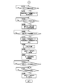
図2に、カール除去装置107の構成の詳細を示す。カール除去装置107は、カール状態検出部200,カール矯正部300,およびカール状態検出部200とカール矯正部300の動作を制御する制御部400とを含んで構成される。なお、カール状態検出部200が本発明のカール状態検出手段に相当する。また、カール矯正部300が本発明のカール矯正手段に相当する。
FIG. 2 shows details of the configuration of the
カール状態検出部200は、画像形成装置100(定着ローラ106)より画像形成されて排出された用紙206を搬送する搬送ローラ201(2個で1組)、カール状態の検出を行うために用紙206を下方に垂らすように下向きに支持する用紙支持ローラ202(2個で1組)、用紙の搬送先を切り替えるための分岐爪203、カール状態の検出が完了した用紙206をカール矯正部300へ搬送する搬送ローラ204(2個で1組)、カール状態の検出を行う超音波センサ205を含んで構成される。
The curl
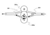
カール矯正部300は、ヒータ301a(図3参照)を備えて発熱可能な発熱ローラ301、発熱ローラ301と接触している上カール除去ローラ302aおよび下カール除去ローラ302b、用紙206をカール除去ローラ302aおよび下カール除去ローラ302bのいずれの側を通過させるかを切り替える分岐爪303を含んで構成される。
The
カール除去ローラ302aおよび302bは弾性ローラであり、発熱ローラ301に押し当てるように構成されており、これらカール除去ローラを押し当てることで、発熱ローラ301との接触部(すなわちニップ部)にニップ力を生じさせている。カール除去ローラ302aおよび302bは、発熱ローラ301の回転に従動して回転するものであるが、モータによりこれらカール除去ローラを駆動する構成としてもよい。
The
図3に、制御部400の構成を示す。制御部400は、モータドライバ401、ヒータドライバ402、超音波センサI/F(インターフェース)403、RAM404、CPU405、ROM406、通信I/F407を含んで構成される。
FIG. 3 shows the configuration of the
モータドライバ401は、CPU405からの回転制御指令に基づいて、用紙支持ローラ202を駆動するための用紙支持ローラ駆動用モータ202m、搬送ローラ201,204を駆動するための搬送ローラ駆動用モータ201m,204m、超音波センサ205を移動するための超音波センサ移動用モータ205m、分岐爪203,303を駆動するための分岐爪駆動用モータ203m,303m、発熱ローラ301を駆動するための発熱ローラ駆動用モータ301mのそれぞれについて回転制御を行うためのドライバIC等を含む回路で構成される。なお、用紙支持ローラ駆動用モータ202mが本発明のローラ回転駆動手段に相当する。また、超音波センサ移動用モータ205mが本発明の移動手段に相当する。また、モータドライバ401が本発明の回転速度制御手段に相当する。
The
上記各モータにより、搬送ローラ201、用紙支持ローラ202、搬送ローラ204は回転駆動されるが、2個のローラをモータにより個別に回転駆動してもよいし、1個のローラのみをモータにより回転駆動し、他方のローラを従動させるようにしてもよい。
Each of the motors rotates the
ヒータドライバ402は、CPU405からの発熱制御指令に基づいて、ヒータ301aの発熱を行うためのものである。なお、ヒータドライバ402が本発明の発熱量制御手段に相当する。
The
超音波センサI/F403は、CPU405からの制御指令に基づいて、超音波センサ205の動作制御およびセンサ検出データの取得を行うためのものである。また、超音波センサ205は、例えば周知のラックアンドピニオン方式を用いた架台205aに取り付けられている。そして、超音波センサ205はピニオン側に取り付けられ、ピニオンギアに取り付けられた超音波センサ移動用モータ205mが回転することでラックギア上を移動するように構成されている。
The ultrasonic sensor I /
通信I/F407は、例えばプリンタ100とのデータ通信を行うための通信インターフェース回路である。
The communication I /
制御部400では、CPU405がROM406に記憶された制御プログラムを実行することで、本発明のカール除去装置としての機能を実現する。また、RAM404は、必要に応じてデータが保存されるワークエリアとして用いられる。
In the
図4および図5を用いて、カール状態検出部200におけるカール状態検出処理について説明する。なお、本処理はROM405に記憶された制御プログラムに含まれ、CPU405により制御プログラムの他の処理とともに繰り返し実行される。
The curl state detection process in the curl
まず、下記のうちのいずれかの方法を用いて、用紙206が印刷されているか否かを検出する(S110)。
・通信I/F407を介して、プリンタ100からの印刷開始信号を取得する。印刷開始信号を取得したときに、用紙が印刷されていることを検出する。
・搬送用ローラ201の上流(すなわちプリンタ100)側に、プリンタ100から搬送される用紙206を検出するためのセンサを取り付ける。センサが用紙を検出すれば、用紙が印刷されていることを検出できる。
First, it is detected whether or not the
A print start signal from the
A sensor for detecting the
用紙206が印刷されていることが検出された場合(S110:Yes)、分岐爪203を用紙206が用紙支持ローラ202側へ搬送されるように下側へ切り替えるために、分岐爪駆動用モータ203mを駆動するようモータドライバ401に回転制御指令を送る(S120)。続いて、搬送ローラ201を駆動するようにモータドライバ401に回転制御指令を送る(S130)。
When it is detected that the
用紙206が搬送ローラ201から搬送され、分岐爪203で用紙を検出した場合(S140:Yes)、用紙支持ローラ202を駆動するようにモータドライバ401に回転制御指令を送る(S150)。用紙支持ローラ202は、搬送ローラ201を駆動するタイミングで駆動させてもよい。なお、分岐爪203には、例えば光センサのような用紙を非接触で検出するためのセンサ203aが取り付けられている。また、搬送ローラ201と分岐爪203との間の搬送経路上に、用紙を検出するためのセンサ(接触,非接触のいずれでもよい)を取り付けてもよい。続いて、用紙支持ローラ駆動用モータ202mの駆動時間の計測を開始する(S160)。
When the
上述のセンサ(203a等)が用紙を検出しなくなった場合(S170:Yes)、搬送ローラ201および用紙支持ローラ202を停止するようにモータドライバ401に回転制御指令を送る(S180)。そして、用紙支持ローラ駆動用モータ202mの駆動時間の計測を終了して、計測時間TをRAM406に記憶する(S190)。
When the above-described sensor (203a or the like) no longer detects a sheet (S170: Yes), a rotation control command is sent to the
また、通信I/F407を介して、プリンタ100から印刷用紙サイズ情報を取得し、その印刷用紙サイズに対応した時間だけ、用紙支持ローラ駆動用モータ202mを駆動するようにしてもよい。
Alternatively, the print paper size information may be acquired from the
図6に、用紙206が用紙支持ローラ202に支持された状態を示す。用紙支持ローラ202は、用紙206を下方に垂らすように下向きに支持している。よって、用紙206はプリンタ100で生じたカールによって湾曲した状態になっている。
FIG. 6 shows a state where the
上述の例では用紙206の後端を用紙支持ローラ202で支持しているが、用紙206のカール量は用紙206の送り方向に対して中間より半分を測定するのみでもよいので、用紙206の搬送方向の中間部までを搬送して、中間部を用紙支持ローラ202で支持する方法でもよい。このようにすることで、用紙206を下方向へ垂らすスペースを削減でき、装置のコンパクト化とコストダウンが可能となる。この場合は、通信I/F407を介して、プリンタ100から印刷用紙サイズ情報を取得可能とする構成とすればよい。そして、用紙支持ローラ駆動用モータ202mの駆動時間を、用紙206の長さの半分に相当する時間とすればよい。この時間は、用紙支持ローラ駆動用モータ202mの回転速度,用紙支持ローラ202の直径が既知であるので算出可能である。
In the above example, the trailing edge of the
次に、超音波センサ移動用モータ205mにより超音波センサ205を用紙206のカール状態を検出できる位置(カール状態検出位置)に移動するために、モータドライバ401に回転制御指令を送る(S200)。図6のように、超音波センサ205は、カールが発生していない用紙206を下向きに垂らした状態で、その用紙206が形成する面(下向き基準面)に対して並行して上下(すなわち略鉛直)方向に移動可能となっている。無論、上下方向に加えて左右(すなわち略水平)方向に移動可能としてもよい。超音波センサ205の移動方法は以下のいずれを用いてもよい。
・通信I/F407を介して、プリンタ100から印刷用紙サイズ情報を取得し、その印刷用紙サイズに対応した位置に移動し、その位置をカール状態検出位置とする。
・RAM406に記憶された、上述の計測時間T,用紙支持ローラ駆動用モータ202mの回転速度,用紙支持ローラ202の直径から、用紙206の上下方向の長さを算出して、用紙206を用紙支持ローラ202の中心位置からその長さだけ下方の位置に移動させ、その位置をカール状態検出位置とする。
・用紙支持ローラ202の中心近傍から、超音波を発しつつ下方向に移動し、その探知距離207を測定し、その探知距離が例えばカール状態検出部200の筐体の側壁面までの距離のような予め定められた値を超えた場合、該予め定められた値を超えない位置まで戻り、その位置をカール状態検出位置とする。
Next, in order to move the
Print paper size information is acquired from the
The length of the
・ From the vicinity of the center of the
そして、超音波センサ205から超音波を発し、用紙206に反射して超音波センサ205に返ってくるまでの時間を計測してカール状態(カール量およびカール方向)を演算する。続いて、検出したカール状態に基づいて、ヒータ301aの発熱量を演算する(S210)。
Then, an ultrasonic wave is emitted from the
図6では超音波センサは1つのみを図示しているが、画像形成される用紙のサイズは様々であるので、用紙サイズの搬送方向の長さに合った数の超音波センサを配置してもよい。ただし、本実施例では、超音波センサ205は上下方向に移動できる機構としているため、用紙サイズにあわせて超音波センサ位置を動作させることができ、複数個の超音波センサを用いる必要がなく、コストダウンできる。
Although only one ultrasonic sensor is shown in FIG. 6, since the size of the paper on which the image is formed varies, the number of ultrasonic sensors corresponding to the length of the paper size in the transport direction is arranged. Also good. However, in this embodiment, since the
図5に移り、図4のステップS210の処理(カール状態検出)が終了した場合(S220:Yes)、用紙206を上方向に搬送するために、用紙支持ローラ202を駆動するようにモータドライバ401に回転制御指令を送る(S230)。つまり、用紙支持ローラ駆動用モータ202mをステップS150のときとは逆回転に駆動する。
Turning to FIG. 5, when the process of step S <b> 210 (curl state detection) in FIG. 4 is completed (S <b> 220: Yes), the
用紙206が用紙支持ローラ202から搬送され、分岐爪203に設けられたセンサ203aあるいは用紙206の搬送経路上に設けられたセンサ(図示せず)により用紙を検出した場合(S240:Yes)、搬送ローラ201をステップS130のときとは逆回転に駆動するようにモータドライバ401に回転制御指令を送る(S250)。
When the
上述のセンサ(203a等)が用紙を検出しなくなった場合(S260:Yes)、搬送ローラ201および用紙支持ローラ202を停止するようにモータドライバ401に回転制御指令を送る(S270)。また、先に計測した計測時間Tの時間だけ、用紙支持ローラ202を駆動してもよい。
When the above-described sensor (203a or the like) no longer detects a sheet (S260: Yes), a rotation control command is sent to the
次に、分岐爪203を用紙206がカール矯正部300側へ搬送されるように切り替えるために、分岐爪駆動用モータ203mを駆動するようモータドライバ401に回転制御指令を送る(S280)。
Next, a rotation control command is sent to the
次に、用紙206がカール矯正部300側へ搬送されるように、搬送ローラ201,204を駆動するようにモータドライバ401に回転制御指令を送る(S290)。続いて、搬送ローラ駆動用モータ201m(204mでもよい)の駆動時間の計測を開始する(S300)。図7に、搬送ローラ201,204の駆動が開始されたときの状態を示す。
Next, a rotation control command is sent to the
上述のセンサ(203a等)が用紙を検出しなくなった場合(S310:Yes)、この時点からの駆動時間を計測し、所定時間経過したか否かを判定する。分岐爪203が用紙の接触を検出しなくなってから所定時間経過した場合、すなわち、用紙206がカール除去装置107から完全に排出された場合(S320:Yes)、搬送ローラ201,204を停止するようにモータドライバ401に回転制御指令を送る(S330)。
When the above-described sensor (203a or the like) no longer detects a sheet (S310: Yes), the driving time from this point is measured, and it is determined whether or not a predetermined time has elapsed. When a predetermined time has elapsed after the branching
図8を用いて、カール矯正部300におけるカール矯正処理について説明する。なお、本処理はROM405に記憶された制御プログラムに含まれ、CPU405により制御プログラムの他の処理とともに繰り返し実行される。
The curl correction processing in the
まず、分岐爪303を切り替えるタイミングであるか否かを判定する。このタイミングは、例えば、用紙206がカール矯正部300側へ搬送されるように、搬送ローラ201,204を駆動したとき(すなわち、図4のステップS290)とする。分岐爪303を切り替えるタイミングであると判定された場合(S510:Yes)、分岐爪303を切り替える(S520)。
First, it is determined whether it is time to switch the
分岐爪303の切り替えは、カールの状態に基づいて行う。図4のカール状態を検出するステップ(S210)において、図6のように左方へカールしている場合は、用紙206がカール矯正部300は搬送される状態では上向きにカールしているので「上カール」と判定される。図6の例とは逆に、右方へカールしている場合は、用紙206がカール矯正部300は搬送される状態では下向きにカールしているので「下カール」と判定される。これは、超音波センサ205から発した超音波が、例えばカールがない場合に返ってくるまでの時間(すなわち超音波が下向き基準面で反射して返ってくるまでの時間)のような予め定められた時間より遅く返ってきた場合は上カールであり、早く帰ってきた場合は下カールであると判定できる。
Switching of the
上カールと判定された場合には、図9のように、分岐爪303を下側に切り替えて用紙206を上カール除去ローラ302a側へ搬送するために、分岐爪駆動用モータ303mを駆動するように、モータドライバ401に回転制御指令を送る。一方、下カールと判定された場合には、図10のように、分岐爪303を上側に切り替えて用紙206を下カール除去ローラ302b側へ搬送するために、分岐爪駆動用モータ303mを駆動するように、モータドライバ401に回転制御指令を送る。図9,図10のいずれのにおいても、用紙206は矢印のように搬送される。
If it is determined that the curl is up, as shown in FIG. 9, the branch
次に、カール状態に応じて発熱ローラ301を駆動するように、モータドライバ401に回転制御指令を送る(S530)とともに、ヒータ301aに通電する(S540)。通電量すなわち発熱量は、図4のステップS210で算出されたものを用いる。図9の上カールの例では発熱ローラ301は反時計回りに回転し、上カール除去ローラ302aは時計回りに従動回転する。また、図10の下カールの例では発熱ローラ301は時計回りに回転し、下カール除去ローラ302bは反時計回りに従動回転する。続いて、発熱ローラ301駆動用モータ301mの駆動時間tの計測を開始する(S550)。そして、発熱ローラ301とカール除去ローラ302aあるいは302bとの間(ニップ部)を用紙206が通過することで、用紙206のカール矯正を行うことができる。
Next, a rotation control command is sent to the
発熱ローラ301駆動用モータ301mの駆動時間tが所定時間(例えば図4のステップS190で記憶されたT、あるいは用紙サイズ毎に予め定められた値)を超えた場合(S560:Yes)、発熱ローラ301を停止するように、モータドライバ401に回転制御指令を送る(S570)。このとき、ヒータ301aの発熱も停止する。また、分岐爪303あるいは用紙206の搬送経路上に、用紙206を検出するためのセンサを設け、検出した用紙の有無に応じてモータ(すなわちローラ)の駆動/停止を行ってもよい。
When the driving time t of the
上述の例では、発熱ローラ301の駆動速度(すなわち回転速度)を一定として、カール状態に応じてヒータ301aの発熱量を変化させるものであるが、ヒータ301aの発熱量を一定としてカール状態に応じて発熱ローラ301の駆動速度を変化させてもよい。発熱ローラ301の駆動速度の演算は、例えば、図4のステップS210でカール量の検出とともに行う。無論、発熱ローラ301駆動用モータ301mを駆動する時間も、駆動速度に基づいて算出する。
In the above example, the heating speed of the heating roller 301 (that is, the rotational speed) is set constant, and the amount of heat generated by the
以上、本発明の実施の形態を説明したが、これらはあくまで例示にすぎず、本発明はこれらに限定されるものではなく、特許請求の範囲の趣旨を逸脱しない限りにおいて、当業者の知識に基づく種々の変更が可能である。 Although the embodiments of the present invention have been described above, these are merely examples, and the present invention is not limited to these embodiments, and the knowledge of those skilled in the art can be used without departing from the spirit of the claims. Various modifications based on this are possible.
100 プリンタ
107 カール除去装置
108 フィニッシャー
200 カール状態検出部(カール状態検出手段)
201 搬送ローラ
202 用紙支持ローラ
202m 用紙支持ローラ駆動用モータ(ローラ回転駆動手段)
203 分岐爪
204 搬送ローラ
205 超音波センサ
205m 超音波センサ移動用モータ(移動手段)
206 用紙
300 カール矯正部(カール矯正手段)
301 発熱ローラ
301a ヒータ(発熱部)
302a 上カール除去ローラ
302b 下カール除去ローラ
303 分岐爪
400 制御部
401 モータドライバ(回転速度制御手段)
402 ヒータドライバ(発熱量制御手段)
403 超音波センサI/F
405 CPU
DESCRIPTION OF
201 Conveying
203
206
301
302a Upper
402 Heater driver (heat generation amount control means)
403 Ultrasonic sensor I / F
405 CPU
Claims (9)
前記用紙を搬送するために、前記用紙支持ローラを回転駆動するローラ回転駆動手段と、
下向きに支持された前記用紙の下端部付近に発生したカール量およびカール方向を含むカール状態を検出するカール状態検出手段と、を備え、
前記ローラ回転駆動手段は、前記カール状態検出手段が前記カール状態を検出した後に、前記用紙を上昇搬送するように前記用紙支持ローラを回転駆動し、
上昇搬送された前記用紙のカール状態に基づいて、該カール状態を矯正するカール矯正手段を備えることを特徴とするカール除去装置。 A sheet support roller that conveys the sheet-like sheet on which the image is formed, holds a predetermined portion of the sheet, and supports the sheet downward so as to hang downward.
Roller rotation driving means for rotating the sheet supporting roller to convey the sheet;
A curl state detection means for detecting a curl state including a curl amount and a curl direction generated near the lower end of the paper supported downward;
The roller rotation driving means rotationally drives the paper support roller so that the paper is lifted and conveyed after the curl state detection means detects the curl state,
An anti-curl removing apparatus comprising curl correcting means for correcting the curl state based on the curl state of the sheet transported upward.
発熱部を含んで回転可能な発熱ローラと、
予め定められた押圧力で前記発熱ローラに押圧されて接触し、該発熱ローラの回転駆動に従動して回転する、または自ら回転駆動して前記発熱ローラを従動させる弾性ローラと、を備え、
回転する前記発熱ローラと前記弾性ローラとの接触部であるニップ部に前記用紙を挟圧しつつ通過させ、該用紙の該発熱ローラに接触している面を熱膨張させることで前記カール状態を矯正する請求項1ないし請求項6のいずれか1項に記載のカール除去装置。 The curl correcting means is
A heat generating roller that includes a heat generating portion and is rotatable;
An elastic roller that is pressed against and contacts the heat generating roller with a predetermined pressing force, and that rotates following the rotation driving of the heat generating roller, or that rotates and drives the heat generating roller by itself.
The paper is passed through a nip portion that is a contact portion between the rotating heat generating roller and the elastic roller while being pressed, and the surface of the paper that is in contact with the heat generating roller is thermally expanded to correct the curl state. The decurler according to any one of claims 1 to 6.
Priority Applications (1)
| Application Number | Priority Date | Filing Date | Title |
|---|---|---|---|
| JP2008319613A JP2010143657A (en) | 2008-12-16 | 2008-12-16 | Curl removing device |
Applications Claiming Priority (1)
| Application Number | Priority Date | Filing Date | Title |
|---|---|---|---|
| JP2008319613A JP2010143657A (en) | 2008-12-16 | 2008-12-16 | Curl removing device |
Publications (1)
| Publication Number | Publication Date |
|---|---|
| JP2010143657A true JP2010143657A (en) | 2010-07-01 |
Family
ID=42564492
Family Applications (1)
| Application Number | Title | Priority Date | Filing Date |
|---|---|---|---|
| JP2008319613A Pending JP2010143657A (en) | 2008-12-16 | 2008-12-16 | Curl removing device |
Country Status (1)
| Country | Link |
|---|---|
| JP (1) | JP2010143657A (en) |
Cited By (1)
| Publication number | Priority date | Publication date | Assignee | Title |
|---|---|---|---|---|
| US9085178B2 (en) | 2013-01-07 | 2015-07-21 | Seiko Epson Corporation | Printing apparatus |
-
2008
- 2008-12-16 JP JP2008319613A patent/JP2010143657A/en active Pending
Cited By (1)
| Publication number | Priority date | Publication date | Assignee | Title |
|---|---|---|---|---|
| US9085178B2 (en) | 2013-01-07 | 2015-07-21 | Seiko Epson Corporation | Printing apparatus |
Similar Documents
| Publication | Publication Date | Title |
|---|---|---|
| US8909124B2 (en) | Image forming apparatus | |
| JP6685792B2 (en) | Image forming device | |
| JP5815493B2 (en) | Sheet conveying apparatus, document conveying apparatus, and image forming apparatus | |
| JP2005049615A (en) | Image forming apparatus | |
| CN101236370B (en) | Imaging device and control method thereof | |
| JP2018106112A (en) | Image forming apparatus and image forming method | |
| JP2006292934A (en) | Image forming apparatus | |
| US10018953B2 (en) | Image processing apparatus | |
| JP2015114634A (en) | Image forming apparatus | |
| JP2011126656A (en) | Curl removing device | |
| US8270858B2 (en) | Image forming device to determine paper width and image forming method thereof | |
| JP2018173517A (en) | Image forming apparatus | |
| JP2010143657A (en) | Curl removing device | |
| JP5354190B2 (en) | Image forming apparatus and image forming system | |
| JP4733575B2 (en) | Inkjet recording device | |
| US10551772B2 (en) | Image forming apparatus and sheet conveying method | |
| JP5590736B2 (en) | Image forming apparatus | |
| JP5953826B2 (en) | Image forming apparatus and method of controlling image forming apparatus | |
| JP6173096B2 (en) | Image forming apparatus | |
| JP7392460B2 (en) | An image forming apparatus, a method for controlling the image forming apparatus, and a program for causing a computer to execute the control method | |
| JP5078819B2 (en) | Image forming apparatus | |
| JP3896249B2 (en) | Paper feeding method in image forming apparatus | |
| JP2007119213A (en) | Image forming apparatus | |
| JP4090485B2 (en) | Image forming apparatus | |
| JP2008129061A (en) | Printed matter and image forming apparatus |