JP2010143494A - Electric power steering device - Google Patents
Electric power steering device Download PDFInfo
- Publication number
- JP2010143494A JP2010143494A JP2008324856A JP2008324856A JP2010143494A JP 2010143494 A JP2010143494 A JP 2010143494A JP 2008324856 A JP2008324856 A JP 2008324856A JP 2008324856 A JP2008324856 A JP 2008324856A JP 2010143494 A JP2010143494 A JP 2010143494A
- Authority
- JP
- Japan
- Prior art keywords
- steering
- reverse input
- torque
- current
- speed
- Prior art date
- Legal status (The legal status is an assumption and is not a legal conclusion. Google has not performed a legal analysis and makes no representation as to the accuracy of the status listed.)
- Granted
Links
Images


Landscapes
- Steering Control In Accordance With Driving Conditions (AREA)
- Power Steering Mechanism (AREA)
Abstract
Description
本発明は、運転者の操舵操作に基づいて電動モータを駆動制御して操舵アシストトルクを発生する電動パワーステアリング装置に関する。 The present invention relates to an electric power steering apparatus that drives and controls an electric motor based on a steering operation of a driver to generate a steering assist torque.
従来から、電動パワーステアリング装置は、電動モータの出力トルクをステアリング機構のステアリングシャフトやラックバーなどに伝達することによって、運転者の操舵操作をアシストする装置として知られている。こうした電動パワーステアリング装置においては、運転者が行った操舵操作に基づいて目標電流を演算し、演算した目標電流が得られるように電動モータの通電を制御している。 2. Description of the Related Art Conventionally, an electric power steering apparatus is known as an apparatus that assists a driver's steering operation by transmitting output torque of an electric motor to a steering shaft or a rack bar of a steering mechanism. In such an electric power steering device, a target current is calculated based on a steering operation performed by a driver, and energization of the electric motor is controlled so that the calculated target current is obtained.
車両の走行中において、例えば、タイヤが縁石に衝突したケースなど、タイヤからステアリング機構に大きな力が加わった場合には、操舵輪が転舵しラックバーに大きな軸力が働く。これにより、ラックバーが軸方向に移動するとともに、ラックバーに連結されたステアリングシャフトが回転する。このようにタイヤからステアリング機構に逆入力が働いて操舵輪が転舵されてしまう状態を逆入力状態と呼ぶ。逆入力が大きい場合には、ラックバーの先端に設けたラックエンド部材が、ラックハウジングに形成されたストッパに衝突し、ステアリング機構に衝撃力が働く。 When a large force is applied from the tire to the steering mechanism, for example, in a case where the tire collides with a curb while the vehicle is running, the steered wheel turns and a large axial force acts on the rack bar. As a result, the rack bar moves in the axial direction and the steering shaft connected to the rack bar rotates. A state in which reverse input is applied to the steering mechanism from the tire and the steered wheels are steered is referred to as a reverse input state. When the reverse input is large, the rack end member provided at the tip of the rack bar collides with a stopper formed on the rack housing, and an impact force acts on the steering mechanism.
そこで、例えば、特許文献1に提案された電動パワーステアリング装置においては、逆入力状態であるか否かを判断し、逆入力状態であると判定したときに、逆入力に対向する向きに操舵アシスト用モータを駆動して、操舵感覚の悪化の低減を図ろうとしている。この電動パワーステアリング装置では、ステアリングシャフトのトーションバーを挟んで入力側の角速度ω1と出力側の角速度ω2とを検出し、車速が比較的大きく、かつ、角速度ω2が角速度ω1より大きい場合に、逆入力状態であると判定している。
しかしながら、特許文献1に提案された電動パワーステアリング装置では、逆入力状態を適切に判定することは困難であった。
However, in the electric power steering device proposed in
本発明の目的は、上記問題に対処するためになされたもので、逆入力状態の判定を適切に行うことにある。 An object of the present invention is to cope with the above problem, and is to appropriately determine a reverse input state.
上記目的を達成するために、本発明の特徴は、ステアリング機構に設けられて操舵アシストトルクを発生する電動モータと、操舵ハンドルに連結されたステアリングシャフトに働く捩り力を操舵トルクとして検出する操舵トルク検出手段と、前記検出した操舵トルクに基づいて目標電流を演算し、演算した目標電流が前記電動モータに流れるように前記電動モータの通電を制御するモータ制御手段と、タイヤからの逆入力により操舵輪が転舵されてしまう逆入力状態を検出する逆入力状態検出手段と、前記逆入力状態が検出されたときに、前記ステアリング機構に働く衝撃を低減する衝撃低減手段とを備えた電動パワーステアリング装置において、
前記逆入力検出手段は、前記目標電流を表す情報と、前記電動モータに実際に出力された実電流を表す情報とを取得する電流情報取得手段と、前記取得した情報に基づいて、前記実電流が前記目標電流よりも小さく、その差が判定基準値を超えた場合に、前記逆入力状態であると判定する電流判定手段とを備えたことにある。
In order to achieve the above object, the present invention is characterized by an electric motor that is provided in a steering mechanism and generates a steering assist torque, and a steering torque that detects a torsional force acting on a steering shaft connected to a steering handle as a steering torque. Steering by means of detection means, motor control means for calculating a target current based on the detected steering torque, and controlling energization of the electric motor so that the calculated target current flows to the electric motor, and reverse input from the tire Electric power steering system comprising reverse input state detecting means for detecting a reverse input state in which a wheel is steered, and impact reducing means for reducing an impact acting on the steering mechanism when the reverse input state is detected In the device
The reverse input detection means includes: current information acquisition means for acquiring information indicating the target current and information indicating the actual current actually output to the electric motor; and the actual current based on the acquired information. Is smaller than the target current, and when the difference exceeds a determination reference value, current determination means for determining the reverse input state is provided.
本発明においては、モータ制御手段が、操舵トルク検出手段により検出した操舵トルクに基づいて目標電流を演算し、演算した目標電流にて電動モータに通電して操舵アシストトルクを発生させる。操舵トルク検出手段は、操舵操作によりステアリングシャフトが捩られるトルクを操舵トルクとして検出する。 In the present invention, the motor control means calculates the target current based on the steering torque detected by the steering torque detection means, and energizes the electric motor with the calculated target current to generate the steering assist torque. The steering torque detecting means detects, as a steering torque, a torque by which the steering shaft is twisted by a steering operation.
逆入力状態検出手段は、タイヤからの逆入力により操舵輪が転舵されてしまう逆入力状態を検出する。この逆入力状態とは、例えば、操舵輪のタイヤが縁石に衝突したケースのように、運転者の操舵操作や電動モータの操舵アシストにかかわらず、強い外力により操舵輪が転舵してしまう状態(ステアリングシャフトや電動モータが回転してしまう状態)を意味し、セルフアライニングトルクのように運転者が保舵できるような弱い外力が働く状態を含むものではない。衝撃低減手段は、逆入力状態が検出されたとき、ステアリング機構に働く衝撃を低減する。 The reverse input state detection means detects a reverse input state in which the steered wheels are steered by the reverse input from the tire. This reverse input state is a state in which the steered wheels are steered by a strong external force regardless of the driver's steering operation or the steering assist of the electric motor, such as a case where the tire of the steered wheels collides with the curb. It means (a state where the steering shaft or the electric motor rotates), and does not include a state where a weak external force that can be maintained by the driver like the self-aligning torque is applied. The impact reducing means reduces the impact acting on the steering mechanism when a reverse input state is detected.
逆入力検出手段は、逆入力状態の検出を適正に行うために、電流情報取得手段と電流判定手段とを備えている。電流情報取得手段は、モータ制御手段が電動モータの通電制御を行うために演算した目標電流を表す情報と、電動モータに実際に出力された(流れた)実電流を表す情報を取得する。実電流は、例えば、電動モータの通電量を検出する電流センサで検出される情報を取得すればよい。電流判定手段は、この情報に基づいて、実電流が目標電流よりも小さく、かつ、その差が判定基準値を超えた場合に、逆入力状態であると判定する。 The reverse input detection means includes a current information acquisition means and a current determination means in order to properly detect the reverse input state. The current information acquisition means acquires information representing the target current calculated by the motor control means for performing energization control of the electric motor, and information representing the actual current actually output (flowed) to the electric motor. For the actual current, for example, information detected by a current sensor that detects the energization amount of the electric motor may be acquired. Based on this information, the current determination unit determines that the current is in the reverse input state when the actual current is smaller than the target current and the difference exceeds the determination reference value.
タイヤの縁石衝突等により逆入力がステアリング機構に働くと、操舵輪が転舵され、それに伴ってステアリングシャフトが急激に捩られながら回転する。ステアリングシャフトが捩られるのは、操舵ハンドルの慣性等により、ステアリングシャフトの車輪側(出力側)に比べて操舵ハンドル側が遅れて回転するためである。モータ制御手段は、このステアリングシャフトの捩れを操舵トルクとして検出して捩り力に対応した高い目標電流を演算し、その目標電流にしたがって電動モータを通電する。 When a reverse input acts on the steering mechanism due to a curb collision of a tire or the like, the steered wheels are steered, and the steering shaft rotates while being abruptly twisted accordingly. The reason why the steering shaft is twisted is that the steering wheel side rotates later than the wheel side (output side) of the steering shaft due to the inertia of the steering wheel. The motor control means detects the twist of the steering shaft as a steering torque, calculates a high target current corresponding to the torsion force, and energizes the electric motor according to the target current.
このとき、通常の操舵操作では想定されない速さでステアリングシャフトが高速回転するため、モータ制御手段による電動モータの通電制御に位相遅れが生じてしまい、実際に電動モータに出力された実電流は目標電流に追従できず低い値となってしまう。 At this time, since the steering shaft rotates at a high speed that is not assumed in normal steering operation, a phase delay occurs in the energization control of the electric motor by the motor control means, and the actual current actually output to the electric motor is the target. It cannot follow the current and becomes a low value.
そこで、逆入力検出手段は、電流判定手段を使って、実電流が目標電流よりも小さく、その差が判定基準値を超えた場合に、逆入力状態であると判定する。従って、逆入力状態を適正に判定することができる。 Therefore, the reverse input detection means uses the current determination means to determine that it is in the reverse input state when the actual current is smaller than the target current and the difference exceeds the determination reference value. Therefore, the reverse input state can be properly determined.
また、本発明の他の特徴は、前記逆入力検出手段は、更に、前記操舵トルク検出手段により検出された操舵トルクを表す情報を取得するトルク情報取得手段と、前記取得した情報に基づいて、前記操舵トルクが運転者の操舵操作では検出されない大きな値に設定された基準トルクよりも大きな値で基準時間以上継続した場合に、前記逆入力状態であると判定するトルク判定手段とを備えたことにある。 Another feature of the present invention is that, based on the acquired information, the reverse input detection means further includes torque information acquisition means for acquiring information representing the steering torque detected by the steering torque detection means, and Torque determination means for determining that the steering wheel is in the reverse input state when the steering torque continues for a reference time at a value larger than a reference torque set to a large value that is not detected by the driver's steering operation. It is in.
タイヤの縁石衝突等により逆入力がステアリング機構に働くと、操舵輪が転舵され、それに伴ってステアリングシャフトが急激に捩られる。この捩り力は、操舵トルクとして操舵トルク検出手段により検出されるが、通常の操舵操作では検出されない非常に大きな値となる。そこで、逆入力検出手段は、トルク情報取得手段とトルク判定手段とにより、こうした事象を捉えて逆入力状態を判定する。つまり、トルク情報取得手段が、操舵トルク検出手段により検出された操舵トルクを表す情報を取得し、トルク判定手段が、操舵トルクが運転者の操舵操作では検出されない大きな値に設定された基準トルクよりも大きな値で基準時間以上継続した場合に、逆入力状態であると判定する。 When a reverse input acts on the steering mechanism due to a curb collision of a tire or the like, the steered wheels are steered, and accordingly, the steering shaft is rapidly twisted. This torsional force is detected as a steering torque by the steering torque detecting means, but becomes a very large value that is not detected by a normal steering operation. Therefore, the reverse input detection means detects such an event and determines the reverse input state by the torque information acquisition means and the torque determination means. That is, the torque information acquisition unit acquires information representing the steering torque detected by the steering torque detection unit, and the torque determination unit determines that the steering torque is greater than the reference torque set to a large value that is not detected by the driver's steering operation. If it continues for more than the reference time with a large value, it is determined that the state is the reverse input state.
従って、本発明によれば、電流判定手段とトルク判定手段との両方に基づいて逆入力状態を判定するため、その判定精度が一層良好なものとなる。例えば、電流判定手段とトルク判定手段のうち何れか一方でも逆入力状態であると判定したときに、逆入力検出手段が逆入力状態である旨の検出結果を出力すれば逆入力状態の検出が遅れない。また、電流判定手段とトルク判定手段との両方が逆入力状態であると判定したときに、逆入力検出手段が逆入力状態である旨の検出結果を出力すれば逆入力状態を確実に検出することができる。この結果、衝撃低減手段によりステアリング機構に働く衝撃を良好に低減することができる。 Therefore, according to the present invention, since the reverse input state is determined based on both the current determination unit and the torque determination unit, the determination accuracy is further improved. For example, if it is determined that either the current determination means or the torque determination means is in the reverse input state, the reverse input state is detected if the reverse input detection means outputs a detection result indicating that the reverse input state is present. There is no delay. Further, when it is determined that both the current determination means and the torque determination means are in the reverse input state, the reverse input state is reliably detected if the detection result that the reverse input detection means is in the reverse input state is output. be able to. As a result, the impact acting on the steering mechanism can be satisfactorily reduced by the impact reducing means.
また、本発明の他の特徴は、前記逆入力検出手段は、更に、操舵速度を表す情報を取得する操舵速度情報取得手段と、前記取得した情報から、前記操舵速度が運転者の操舵操作では回転できない高速に設定された基準速度よりも大きい場合に、前記逆入力状態であると判定する速度判定手段とを備えたことにある。 According to another aspect of the present invention, the reverse input detection means further includes a steering speed information acquisition means for acquiring information indicating a steering speed, and the steering speed is determined by the driver's steering operation from the acquired information. And a speed determining means for determining that the reverse input state is established when the speed is higher than a reference speed set at a high speed that cannot be rotated.
タイヤの縁石衝突等により逆入力がステアリング機構に働くと、操舵輪が転舵され、それに伴ってステアリングシャフトが回転する。このときのステアリングシャフトの回転速度は、非常に大きく、運転者の操舵操作では回転できない速さとなる。そこで、逆入力検出手段は、操舵速度情報取得手段と速度判定手段とにより、こうした事象を捉えて逆入力状態を判定する。つまり、操舵速度情報取得手段が、操舵速度を表す情報を取得し、速度判定手段が、操舵速度が運転者の操舵操作では回転できない高速に設定された基準速度よりも大きい場合に、逆入力状態であると判定する。 When reverse input acts on the steering mechanism due to a curb collision of the tire or the like, the steering wheel is steered, and the steering shaft rotates accordingly. At this time, the rotation speed of the steering shaft is very large and cannot be rotated by the driver's steering operation. Therefore, the reverse input detection means captures such an event and determines the reverse input state by the steering speed information acquisition means and the speed determination means. That is, when the steering speed information acquisition means acquires information indicating the steering speed, and the speed determination means is larger than the reference speed set at a high speed that cannot be rotated by the driver's steering operation, the reverse input state is established. It is determined that
従って、本発明によれば、電流判定手段と速度判定手段、あるいは、電流判定手段と速度判定手段とトルク判定手段とに基づいて逆入力状態を判定するため、その判定精度が一層良好なものとなる。この場合、電流判定手段と速度判定手段のうち何れか一方でも逆入力状態であると判定したとき、あるいは、電流判定手段と速度判定手段との両方が逆入力状態であると判定したときに、逆入力検出手段が逆入力状態である旨の検出結果を出力する。また、電流判定手段と速度判定手段とトルク判定手段とに基づいて逆入力状態を判定する場合には、その3つの判定手段のうちの1つでも逆入力状態であると判定したとき、あるいは、電流判定手段と速度判定手段とトルク判定手段のうち3つあるいは2つが逆入力状態であると判定したときに、逆入力検出手段が逆入力状態である旨の検出結果を出力する。従って、逆入力状態を良好に検出できるため、衝撃低減手段によりステアリング機構に働く衝撃を良好に低減することができる。尚、操舵速度情報は、ステアリングシャフトの回転角速度に限らず、電動モータの回転角速度を検出することにより取得することができる。 Therefore, according to the present invention, since the reverse input state is determined based on the current determination unit and the speed determination unit, or the current determination unit, the speed determination unit, and the torque determination unit, the determination accuracy is further improved. Become. In this case, when it is determined that either the current determination unit or the speed determination unit is in the reverse input state, or when it is determined that both the current determination unit and the speed determination unit are in the reverse input state, A detection result indicating that the reverse input detection means is in the reverse input state is output. Further, when the reverse input state is determined based on the current determination unit, the speed determination unit, and the torque determination unit, when it is determined that one of the three determination units is in the reverse input state, or When it is determined that three or two of the current determination unit, speed determination unit, and torque determination unit are in the reverse input state, the detection result indicating that the reverse input detection unit is in the reverse input state is output. Therefore, since the reverse input state can be detected well, the impact acting on the steering mechanism can be satisfactorily reduced by the impact reducing means. Note that the steering speed information can be acquired not only by the rotational angular speed of the steering shaft but also by detecting the rotational angular speed of the electric motor.
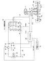
以下、本発明の一実施形態に係る電動パワーステアリング装置について図面を用いて説明する。図1は、同実施形態に係る車両の電動パワーステアリング装置の概略構成を表している。 Hereinafter, an electric power steering apparatus according to an embodiment of the present invention will be described with reference to the drawings. FIG. 1 shows a schematic configuration of an electric power steering apparatus for a vehicle according to the embodiment.
この電動パワーステアリング装置は、操舵ハンドル11の操舵操作により操舵輪である左前輪Wflと右前輪Wfrとを転舵するステアリング機構10と、ステアリング機構10に組み付けられ操舵アシストトルクを発生する電動モータ20と、電動モータ20を駆動するためのモータ駆動回路30と、電動モータ20の作動を制御する電子制御装置100とを主要部として備えている。以下、電子制御装置100をアシストECU100と呼ぶ。
This electric power steering apparatus includes a
ステアリング機構10は、操舵ハンドル11の回動操作に連動したステアリングシャフト12の軸線周りの回転をラックアンドピニオン機構13によりラックバー14の左右方向のストローク運動に変換して、このラックバー14のストローク運動により左前輪Wflと右前輪Wfrとを転舵するようになっている。ステアリングシャフト12は、操舵ハンドル11を上端に連結したメインシャフト12aと、ラックアンドピニオン機構13と連結されるピニオンシャフト12cと、メインシャフト12aとピニオンシャフト12cとをユニバーサルジョイント12d,12eを介して連結するインターミディエイトシャフト12bとから構成される。
The
ラックバー14は、ギヤ部14aがラックハウジング15内に収納され、その左右両端がラックハウジング15から露出してタイロッド16と連結される。左右のタイロッド16の他端は、左右前輪Wfl,Wfrに設けられたナックル17に接続される。ラックバー14のタイロッド16との連結部には、ラックエンド部材18が設けられている。一方、ラックハウジング15の両端には、ストッパ部15aが形成されている。ラックバー14は、ラックエンド部材18とストッパ部15aとの当接により、その左右のストローク移動範囲が機械的に制限される。以下、ラックバー14がストッパ部15aにより移動制限される位置をストロークエンドと呼ぶ。また、左前輪Wflと右前輪Wfrとを単に操舵輪Wと呼ぶ。
The
ステアリングシャフト12(メインシャフト12a)には減速ギヤ19を介して電動モータ20が組み付けられている。電動モータ20は、例えば、三相ブラシレスモータが使用される。電動モータ20は、ロータの回転により減速ギヤ19を介してステアリングシャフト12をその中心軸周りに回転駆動して、操舵ハンドル11の回動操作に対してアシストトルクを付与する。
An
電動モータ20には、モータ回転角センサ21が設けられる。このモータ回転角センサ21は、例えば、レゾルバにより構成され、電動モータ20のロータの回転角度θmを表す検出信号を出力する。モータ回転角θmは、電動モータ20の電気角θeの計算に利用される。以下、モータ回転角センサ21を、単に回転角センサ21と呼ぶ。
The
電動モータ20とステアリングシャフト12とが減速ギヤ19を介して連結されていることから、回転角センサ21で検出されるモータ回転角θmは、操舵ハンドル11の操舵角に対応したものとなる。従って、回転角センサ21は、電動モータ20の電気角θeの検出に使用されるだけでなく、操舵角検出用のセンサとしても使用される。以下、舵角中立点を基準とした回転角度に対応した操舵角を操舵角θhと呼ぶ。また、ステアリングシャフト12の回転速度である操舵速度は、モータ回転角θmあるいは操舵角θhを時間微分演算して求めることができる。以下、このようにして算出される操舵速度を操舵速度ωと呼ぶ。尚、操舵角θhは、基準舵角中立点に対して右方向の操舵角を正の値で、基準舵角中立点に対して左方向の操舵角を負の値で表すことにする。また、操舵速度ωは、操舵ハンドル11が右方向に回転しているときの操舵速度を正の値で、操舵ハンドル11が左方向に回転しているときの操舵速度を負の値で表すことにする。また、操舵角や操舵速度の大きさについて論じる場合には、その絶対値を用いる。
Since the
ステアリングシャフト12(メインシャフト12a)には、操舵ハンドル11と減速ギヤ21との間に操舵トルクセンサ22が設けられている。操舵トルクセンサ22は、ステアリングシャフト12(メインシャフト12a)に介装されているトーションバー(図示略)に働いた捩り力を、操舵ハンドル11に付与された操舵トルクTとして検出する。例えば、トーションバーの両端にレゾルバを設け、この2つのレゾルバにより検出される回転角度の差に基づいて操舵トルクTを検出する。
A
尚、操舵トルクTは、ステアリングシャフト12に右回転方向に働くトルク(トーションバーの上部が下部に対して相対的に右回転位置となる捩り状態でのトルク)を正の値で、左回転方向に働くトルク(トーションバーの上部が下部に対して相対的に左回転位置となる捩り状態でのトルク)を負の値で表すことにする。また、操舵トルクの大きさについて論じる場合には、その絶対値を用いる。 The steering torque T is a positive value for torque acting in the clockwise direction on the steering shaft 12 (torque in a torsional state where the upper portion of the torsion bar is in the right rotational position relative to the lower portion). (Torque in a torsional state where the upper part of the torsion bar is in the left rotation position relative to the lower part) is expressed by a negative value. When discussing the magnitude of the steering torque, the absolute value is used.
モータ駆動回路30は、MOS−FET(Metal Oxide Semiconductor Field Effect Transistor)からなる6個のスイッチング素子31〜36により3相インバータ回路を構成したものである。具体的には、第1スイッチング素子31、第3スイッチング素子33,第5スイッチング素子35を並列に設けた上アーム回路と、第2スイッチング素子32、第4スイッチング素子34,第6スイッチング素子36を並列に設けた下アーム回路とを直列接続し、上下のアーム回路の間から電動モータ20への電力供給ライン37を引き出した構成を採用している。
The
モータ駆動回路30には、電動モータ20に流れる電流を検出する電流センサ38が設けられる。この電流センサ38は、各相(U相,V相,W相)ごとに流れる電流をそれぞれ検出し、その検出した電流値に対応した検出信号をアシストECU100に出力する。以下、この測定された3相の電流値をモータ電流Iuvwと総称する。
The
モータ駆動回路30の各スイッチング素子31〜36は、それぞれゲートがアシストECU100に接続され、アシストECU100から出力されるPWM制御信号によりデューティ比が制御される。これにより電動モータ20の駆動電圧が目標電圧に調整される。尚、図中に回路記号で示すように、スイッチング素子31〜36を構成するMOSFETには、構造上ダイオードが寄生している。
As for each switching element 31-36 of the
アシストECU100は、CPU,ROM,RAM等からなるマイクロコンピュータを主要部として構成される。アシストECU100は、回転角センサ21、操舵トルクセンサ22、電流センサ38、および、車速を検出する車速センサ25を接続し、モータ回転角θm、操舵トルクT、モータ電流Iuvw、車速vを表す検出信号を入力する。そして、入力した検出信号に基づいて、運転者の操舵操作に応じた最適な操舵アシストトルクが得られるように電動モータ20に流す指令電流(目標電流)を演算し、その指令電流が流れるようにモータ駆動回路30の各スイッチング素子31〜36のデューティ比を制御する。
The assist
また、アシストECU100は、タイヤからの逆入力により操舵輪Wが転舵されてしまう逆入力状態を検出する機能と、逆入力状態を検出したときに、ステアリング機構10(特に、ステアリングシャフト12)に働く衝撃を低減する機能をも備えている。アシストECU100の機能については後述する。
Further, the assist
次に、電動パワーステアリング装置の電源供給系統について説明する。電動パワーステアリング装置は、車載電源装置80から電源供給される。車載電源装置80は、定格出力電圧12Vの一般的な車載バッテリである主バッテリ81と、エンジンの回転により発電する定格出力電圧14Vのオルタネータ82とを並列接続して構成される。車載電源装置80には、電源供給元ライン83と接地ライン84が接続される。電源供給元ライン83は、制御系電源ライン85と駆動系電源ライン86とに分岐する。制御系電源ライン85は、アシストECU100に電源供給するための電源ラインとして機能する。駆動系電源ライン86は、モータ駆動回路30とアシストECU100との両方に電源供給する電源ラインとして機能する。
Next, a power supply system of the electric power steering apparatus will be described. The electric power steering device is supplied with power from an in-vehicle
制御系電源ライン85には、イグニッションスイッチ87が接続される。駆動系電源ライン86には、主電源リレー88が接続される。この主電源リレー88は、アシストECU100からのオン信号により接点を閉じて電動モータ20への電力供給回路を形成し、オフ信号により接点を開いて電動モータ20への電力供給回路を遮断するものである。制御系電源ライン85は、アシストECU100の電源+端子に接続されるが、その途中で、イグニッションスイッチ87よりも負荷側(アシストECU100側)においてダイオード89を備えている。このダイオード89は、カソードをアシストECU100側、アノードを車載電源装置80側に向けて設けられ、電源供給方向にのみ通電可能とする逆流防止素子である。
An
駆動系電源ライン86には、主電源リレー88よりも負荷側において制御系電源ライン85と接続する連結ライン90が分岐して設けられる。この連結ライン90は、制御系電源ライン85におけるダイオード89の接続位置よりもアシストECU100側に接続される。また、連結ライン90には、ダイオード91が接続される。このダイオード91は、カソードを制御系電源ライン85側に向け、アノードを駆動系電源ライン86側に向けて設けられる。従って、連結ライン91を介して駆動系電源ライン86から制御系電源ライン85には電源供給できるが、制御系電源ライン85から駆動系電源ライン86には電源供給できないような回路構成となっている。駆動系電源ライン86および接地ライン84は、モータ駆動回路30の電源入力部に接続される。また、接地ライン84は、アシストECU100の接地端子にも接続される。
The drive
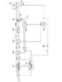
次に、アシストECU100の機能について図2を用いて説明する。図2は、アシストECU100のマイクロコンピュータのプログラム制御により処理される機能を表す機能ブロック図である。
Next, functions of the assist
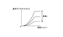
図2に示すように、アシストECU100は、アシスト電流指令部101を備えている。アシスト指令部101は、後述する逆入力状態判定部110により逆入力状態が検出されていないとき(通常時)と、逆入力状態が検出された後とで、その制御形態を切り替える。まず、通常時における制御形態について説明する。アシスト電流指令部101は、図3に示すように、操舵トルクTと車速vとに応じて基本アシストトルクTasを設定するための基本アシストトルクテーブルを記憶する。アシスト電流指令部101は、操舵トルクセンサ22から出力される操舵トルクT及び車速センサ25から出力される車速vを入力して、この基本アシストトルクテーブルを参照することにより基本アシストトルクTasを計算する。基本アシストトルクTasは、操舵トルクTの増加にしたがって増加するとともに車速vの増加にしたがって減少するように設定されている。尚、図3においては、右方向に操舵したときのアシストトルクテーブルを表しているが、左方向に操舵した場合は、基本アシストトルクTasの方向が異なるだけで、その大きさは同じである。
As shown in FIG. 2, the assist
また、アシスト電流指令部101は、回転角センサ21により検出されるモータ回転角θmを舵角中立点を基準とした角度に変換した操舵角θh、および、モータ回転角θmを時間微分した操舵速度ωを算出し、これらを使って、基本アシストトルクTasに対する補償値Tcを計算する。補償値Tcは、例えば、操舵角θhに比例して大きくなるステアリングシャフト12の基本位置への復帰力と操舵速度ωに比例して大きくなるステアリングシャフト12の回転に対する抵抗力に対応した戻しトルクとの和として計算される。アシスト電流指令部101は、計算した基本アシストトルクTasと補償値Tcの和を目標アシストトルクT*として設定し、この目標アシストトルクT*をトルク定数で除算することにより、d−q座標系におけるq軸指令電流Iq*を算出する。
The assist
アシストECU100は、3相通電制御を行う場合には、電動モータ20の回転方向をq軸とするとともに回転方向と直交する方向をd軸とするd−q座標系で記述されるベクトル制御によって電動モータ20の回転を制御する。q軸電流は、電動モータ20にトルクを発生させるが、d軸電流は、電動モータ20にトルクを発生させるものではなく界磁制御に使用される。本実施形態におけるアシスト電流指令部101は、逆入力状態が検知されないかぎり、d軸指令電流Id*をゼロ(Id*=0)に設定する。
When performing three-phase energization control, the assist
このように計算されたq軸指令電流Iq*とd軸指令電流Id*は、フィードバック制御部102に出力される。フィードバック制御部102は、q軸指令電流Iq*からq軸実電流Iqを減算した偏差ΔIqを算出し、この偏差ΔIqを使った比例積分制御によりq軸実電流Iqがq軸指令電流Iq*に追従するようにq軸指令電圧Vq*を計算する。同様に、d軸指令電流Id*からd軸実電流Idを減算した偏差ΔIdを算出し、この偏差ΔIdを使った比例積分制御によりd軸実電流Idがd軸指令電流Id*に追従するようにd軸指令電圧Vd*を計算する。
The q-axis command current Iq * and the d-axis command current Id * calculated in this way are output to the
q軸実電流Iqおよびd軸実電流Idは、電動モータ20のコイルに実際に流れた3相電流の検出値Iu,Iv,Iwをd−q座標系の2相電流に変換したものである。この3相電流Iu,Iv,Iwからd−q座標系の2相電流Id,Iqへの変換は、3相/2相変換部103によって行われる。3相/2相変換部103は、回転角変換部104から出力されるモータ電気角θeを入力し、そのモータ電気角θeに基づいて、電流センサ38から出力される3相電流Iu,Iv,Iwをd−q座標系の2相電流Id,Iqに変換する。回転角変換部104は、回転角センサ21から出力される回転角θmに基づいて、モータ電気角θeを算出する。
The q-axis actual current Iq and the d-axis actual current Id are obtained by converting the detected values Iu, Iv, and Iw of the three-phase current actually flowing in the coil of the
フィードバック制御部102により算出されたq軸指令電圧Vq*とd軸指令電圧Vd*は、2相/3相座標変換部105に出力される。2相/3相座標変換部105は、回転角変換部104から出力される電気角θeに基づいて、q軸指令電圧Vq*とd軸指令電圧Vd*を3相指令電圧Vu*,Vv*,Vw*に変換して、その変換した3相指令電圧Vu*,Vv*,Vw*をPWM信号発生部106に出力する。PWM信号発生部106は、3相指令電圧Vu*,Vv*,Vw*に対応したPWM制御信号をモータ駆動回路30のスイッチング素子31〜36に出力する。これにより電動モータ20が駆動され、目標アシストトルクT*に追従した操舵アシストトルクがステアリング機構10に付与される。
The q-axis command voltage Vq * and the d-axis command voltage Vd * calculated by the
次に、逆入力状態の検出機能について説明する。タイヤの縁石衝突等により大きな逆入力がステアリング機構10に働くと、操舵輪Wが転舵され、それに伴ってステアリングシャフト12が急激に捩られる。これは、操舵ハンドル11の慣性および電動モータ20の慣性により、ステアリングシャフト12のラックバー14側(出力側)に比べて操舵ハンドル12側(入力側)が遅れて回転するためである。そして、ステアリングシャフト12は、トーションバーを強く捩りながら回転速度を急激に増加させて高速で回転する。
Next, the reverse input state detection function will be described. When a large reverse input is applied to the
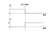
こうした逆入力が発生した直後においては、アシスト電流指令部101は、操舵トルクT(トーションバーの捻れトルク)の急増にしたがって、q軸指令電流Iq*を増加させる。しかし、通常の操舵操作では想定されない速さでステアリングシャフト12が高速回転するため、電気角θeの変化が速すぎてアシストECU100による電動モータ20の通電制御に位相遅れが生じてしまう。このため、図4に示すように、トルク発生方向であるq軸方向に流すべき電流がd軸方向にずれてしまい、実際に電動モータ20に出力できるq軸実電流Iqが低下する。この結果、図5に示すように、ステアリングシャフト12の回転数が非常に高速となった時刻t1から、q軸実電流Iqがq軸指令電流Iq*に対して低下していく。尚、図5は、逆入力が発生した直後からのq軸指令電流Iq*とq軸実電流Iqとの推移を表す。
Immediately after the occurrence of such reverse input, the assist
そこで、アシストECU100は、図2に示すように、逆入力状態判定部110を備え、こうした現象を捉えることにより逆入力状態を検出する。
Therefore, the assist
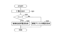
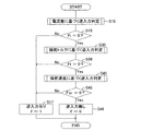
ここで、逆入力状態判定部110の処理についてフローチャートを使って説明する。図6は、逆入力判定部110の実行する逆入力判定ルーチンを表すフローチャートである。逆入力判定ルーチンは、アシストECU100のROM内に制御プログラムとして記憶されている。アシストECU100は、イグニッションスイッチ87の投入により初期診断を行った後に上述した操舵アシスト制御を開始するが、この逆入力判定ルーチンもそれと並行して開始され、所定の短い周期で繰り返される。
Here, the process of the reverse input
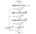
逆入力判定ルーチンが開始されると、逆入力状態判定部110は、ステップS11において、アシスト電流指令部101の出力するq軸指令電流Iq*と、3相/2相変換部103の出力するq軸実電流Iqとを読み込む。つまり、q軸における目標電流と実電流とを読み込む。続いて、ステップS12において、電流値の大きさの差である電流差ΔIqを算出する。この電流差ΔIqは、次式により算出される。
ΔIq=|Iq*|−|Iq|
尚、q軸電流は、電動モータ20に右方向の操舵トルクを発生させるように流れる電流を正の値で、左方向の操舵トルクを発生させるように流れる電流を負の値で表す。従って、ここでは、電流値の大きさを比較するため、絶対値を用いて電流差ΔIqを算出する。
When the reverse input determination routine is started, the reverse input
ΔIq = | Iq * | − | Iq |
The q-axis current is a positive value for a current flowing so as to generate a right steering torque in the
続いて、ステップS13において、電流差ΔIqが判定基準値Iref(正の値)より大きいか否かを判断する。逆入力が発生していない場合には、電流フィードバック制御によりq軸指令電流Iq*とq軸実電流Iqとの差は少ない。しかし、逆入力が発生した場合、上述したようにステアリングシャフト12が高速回転するため、q軸指令電流Iq*の増加に対してq軸実電流Iqが減少していく。従って、q軸実電流Iqの大きさ|Iq|は、q軸指令電流Iq*の大きさ|Iq*|に比べて小さく、しかも、その差が大きくなる。そこで、逆入力状態判定部110は、電流差ΔIqの大きさに基づいで逆入力が発生したか否かを判定する。
Subsequently, in step S13, it is determined whether or not the current difference ΔIq is larger than a determination reference value Iref (positive value). When no reverse input occurs, the difference between the q-axis command current Iq * and the q-axis actual current Iq is small by current feedback control. However, when reverse input occurs, the steering
逆入力状態判定部110は、電流差ΔIqが判定基準値Iref以下である場合には、ステップS14において、逆入力が発生していないと判定するとともに、逆入力判定フラグFを0に設定し(F=0)、その逆入力判定フラグFをアシスト電流指令部101に出力する。そして、逆入力判定ルーチンを一旦終了する。逆入力判定ルーチンは、所定の短い周期で繰り返し実行される。従って、逆入力が発生していないと判定されている期間においては、逆入力判定フラグF=0の信号がアシスト電流指令部101に出力されることになる。
When the current difference ΔIq is equal to or smaller than the determination reference value Iref, the reverse input
一方、電流差ΔIqが判定基準値Irefを越えた場合(S13:Yes)には、ステップS15において、逆入力が発生していると判定するとともに、逆入力判定フラグFを1に設定し(F=1)、その逆入力判定フラグFをアシスト電流指令部101に出力して本ルーチンを一旦終了する。逆入力判定ルーチンは、所定の短い周期で繰り返し実行されるため、逆入力が発生していると判定されている期間においては、逆入力判定フラグF=1の信号がアシスト電流指令部101に出力されることになる。
On the other hand, if the current difference ΔIq exceeds the determination reference value Iref (S13: Yes), it is determined in step S15 that reverse input has occurred, and the reverse input determination flag F is set to 1 (F = 1), the reverse input determination flag F is output to the assist
アシスト電流指令部101は、こうした逆入力状態判定部110の判定に応じて制御形態を切り替える。図7は、アシスト電流指令部101の実行する制御形態切替ルーチンを表すフローチャートである。制御形態切替ルーチンは、アシストECU100のROM内に制御プログラムとして記憶されており、イグニッションスイッチ87の投入により初期診断を行った後に開始され、所定の短い周期で繰り返される。
The assist
本ルーチンが起動すると、アシスト電流指令部101は、ステップS21において、逆入力状態判定部110から逆入力判定フラグFを読み込む。続いて、ステップS22において、逆入力判定フラグFが1に設定されている(F=1)か否かを判断する。逆入力判定フラグFが0に設定されている(F=0)場合、つまり、逆入力状態でない場合、ステップS23において、通常の操舵アシスト制御用の電流指令値を出力する制御形態に設定する。従って、アシスト電流指令部101は、上述したように、操舵トルクTと車速vとから基本アシストトルクTasを演算するとともに操舵角θhと操舵速度ωとから補償値Tcを演算し、これらの和(Tas+Tc)により目標アシストトルクT*を求め、この目標アシストトルクT*をトルク定数で除算してq軸指令電流Iq*を算出する。また、d軸指令電流Id*をゼロに設定する。
When this routine is started, the assist
アシスト電流指令部101は、ステップS23において操舵アシスト用の電流指令をフィードバック制御部102出力すると、制御形態切替ルーチンを一旦終了する。制御形態切替ルーチンは、所定の短い周期で繰り返される。従って、逆入力状態でない期間においては、こうした電流指令値の演算が繰り返され、電流フィードバック制御により適切な操舵アシストトルクが得られる。
When the assist
一方、逆入力判定フラグFが1に設定されている場合(S22:Yes)、つまり、逆入力状態が検出されている場合、アシスト電流指令部101は、ステップS24において、衝撃低減用の電流指令を出力する制御形態に設定する。本実施形態においては、図8に示すように、q軸指令電流Iq*をゼロに設定するとともに、d軸指令電流Id*を電動モータ20がロックされる方向、つまり、界磁を増加させる方向の一定値Idcに設定する。一般に、d軸電流は弱め界磁用に使用されるが、本実施形態においては、その逆方向に流すことで界磁を強める。従って、衝撃低減用の指令電流(Iq*=0、Id*=Idc)により電動モータ20の通電が制御され、電動モータ20の回転に対してブレーキが働く。
On the other hand, when the reverse input determination flag F is set to 1 (S22: Yes), that is, when the reverse input state is detected, the assist
操舵輪Wのタイヤが縁石に衝突したケースのように、ステアリング機構10に強い逆入力が働くと、操舵輪Wが転舵されラックバー14が軸方向に移動する。これにより、ラックバー14の軸方向の運動エネルギーがラックアンドピニオン機構13を介してステアリングシャフト12に伝達され、ステアリングシャフト12が回転する。また、ステアリングシャフト12の回転により、電動モータ20のロータが同方向に回されることとなる。そして、ラックバー14がストロークエンドに達して、ラックバー14の両端に設けたストッパ18の一方が、ラックハウジング15の端部に衝突する。以下、この衝突をストロークエンド衝突と呼ぶ。
When a strong reverse input is applied to the
ストロークエンド衝突が起きると、ステアリングシャフト12の出力側の回転はラックバー14の停止により規制されるが、ステアリングシャフト12の入力側は、開放されているためハンドル慣性トルクとモータ慣性トルクとにより更に回転する。このため、ストロークエンド衝突時には、ステアリングシャフト12における減速ギヤ19より出力側が捩られて大きな衝撃が加わる。特に、本実施形態のように、ステアリングシャフト12に減速ギヤ19を介して電動モータ20を連結しているコラムアシスト方式においては、電動モータ20の慣性トルクが大きく影響するため衝撃が大きい。従って、ステアリングシャフト12の強度(インターミディエイトシャフト12b、ピニオンシャフト12c、および、それらを連結するユニバーサルジョイント12d,12eの強度)を高くする必要がある。
When a stroke end collision occurs, the rotation of the output side of the steering
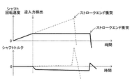
そこで、本実施形態においては、逆入力状態を検知したときに、直ちに、衝撃低減用の指令電流(Iq*=0、Id*=Idc)に切り替えて電動モータ20の回転に対してブレーキを働かせるため、ストロークエンドに達する前にラックバー14の移動速度の上昇を抑えることができ、衝突による衝撃を緩和することができる。図9は、逆入力が発生したときのステアリングシャフト12の回転速度(シャフト回転速度)の推移と、ステアリングシャフト12に働くトルク(シャフトトルク)の推移とを、本実施形態によりブレーキ制動を加えた場合(実線)と、ブレーキ制動を加えない場合(破線)とについて表したグラフである。図示するように、ブレーキ制動を加えない場合には、モータ回転速度が増加していくため、ストロークエンド衝突時における衝撃(シャフトトルク)が大きいが、ブレーキ制動を加えた場合には、逆入力検出以降においてシャフト回転速度の上昇を抑えることができ、ストロークエンド衝突時における衝撃を弱めることができる。
Therefore, in the present embodiment, when the reverse input state is detected, it is immediately switched to the command current for reducing the impact (Iq * = 0, Id * = Idc), and the brake is applied to the rotation of the
アシスト電流指令部101は、ステップS24において衝撃低減用の電流指令をフィードバック制御部102出力すると、制御形態切替ルーチンを一旦終了する。制御形態切替ルーチンは、所定の短い周期で繰り返される。従って、逆入力状態が検出されている期間においては、電動モータ20のブレーキ制動が継続される。尚、こうした逆入力の発生を検出した後においては、図示しないウォーニングランプ等を点滅して運転者に点検を促すようにしてもよい。
When the assist
以上説明した本実施形態の電動パワーステアリング装置によれば、電流差ΔIqに基づいて逆入力状態を判定するため、その判定精度が高い。従って、ステアリング機構10、特に、ステアリングシャフト12に加わる衝撃を適正に低減することができる。この結果、ステアリング機構10の耐久性を向上させることができる。また、操舵ハンドル11から運転者に伝わる衝撃を低減することできる。
According to the electric power steering apparatus of the present embodiment described above, the determination accuracy is high because the reverse input state is determined based on the current difference ΔIq. Therefore, the impact applied to the
次に、逆入力状態判定部110の処理に関する他の実施形態について説明する。尚、上述した実施形態を第1実施形態と呼び、以下に示す実施形態を第2実施形態と呼ぶ。また、図2において、第2実施形態に係る特有の構成については、破線にて示している。
第1実施形態においては、電流差ΔIqに基づいて逆入力状態を判定したが、この第2実施形態においては、電流差ΔIqだけでなく、操舵トルクT、および、操舵速度ωに基づいて逆入力状態を判定する。図10は、第2実施形態としての逆入力判定部110の実行する逆入力判定ルーチンを表すフローチャートである。この逆入力判定ルーチンは、アシスト電流指令部101の処理と並行して実行され、所定の短い周期で繰り返される。
Next, another embodiment relating to the processing of the reverse input
In the first embodiment, the reverse input state is determined based on the current difference ΔIq. However, in the second embodiment, the reverse input is based not only on the current difference ΔIq but also on the steering torque T and the steering speed ω. Determine the state. FIG. 10 is a flowchart illustrating a reverse input determination routine executed by the reverse
本ルーチンが開始されると、逆入力状態判定部110は、ステップS10において、電流差ΔIqに基づく逆入力状態判定処理を行う。このステップS10の処理は、上述した図6に示す実施形態の逆入力判定ルーチンの処理と同じである。ただし、上述したステップS14,15の処理においては、逆入力判定フラグをFiとし、逆入力が発生していると判定したときにはFi=1、逆入力が発生していないと判定したときにはFi=0に設定するものとする。
When this routine is started, the reverse input
続いて、逆入力状態判定部110は、ステップS16において、逆入力判定フラグFiが0であるか否かを判断する。逆入力判定フラグFiが1に設定されている(Fi=1)場合、つまり、電流差ΔIqに基づいて逆入力状態であると判定されている場合には、ステップS17において、逆入力判定フラグFを1に設定し(F=1)、その逆入力判定フラグFをアシスト電流指令部101に出力する。
Subsequently, the reverse input
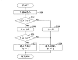
一方、逆入力判定フラグFiが0に設定されている(Fi=0)場合には、ステップS30の操舵トルクに基づく逆入力判定処理を行う。このステップS30の処理については、図11のサブルーチンに沿って実行される。まず、ステップS31において、操舵トルクセンサ22により検出される操舵トルクTを読み込む。続いて、操舵トルクTの大きさ|T|が予め設定した判定基準トルクTrefより大きいか否かを判断する。この判定基準トルクTrefは、運転者による操舵操作では検出されない大きな値に設定されている。
On the other hand, when the reverse input determination flag Fi is set to 0 (Fi = 0), the reverse input determination process based on the steering torque in step S30 is performed. The processing in step S30 is executed according to the subroutine of FIG. First, in step S31, the steering torque T detected by the
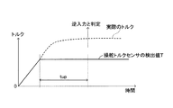
ここで、操舵トルクTに基づいて逆入力状態を判定する原理について説明する。操舵輪Wのタイヤの縁石衝突等により逆入力がステアリング機構10に働くと、操舵輪Wが転舵され、それに伴ってステアリングシャフト12のトーションバーが急激に捩られる。この捩り力は、操舵トルクTとして操舵トルクセンサ22により検出されるが、通常の操舵操作では検出されない非常に大きな値となる。例えば、図12に示すように、ステアリングシャフト12のトーションバーを捩るように働く実際のトルク(破線にて示す)は、操舵トルクセンサ22の検出可能な範囲を超える。そのため、操舵トルクセンサ22の検出値T(実線にて示す)は、最大値を維持した状態が続く。いわゆる、検出値が振り切れた状態である。そこで、判定基準トルクTrefを操舵トルクセンサ22にて検出できる最大値近傍(最大値よりやや小さめの値)に設定しておくことで、逆入力状態を判定することができる。
Here, the principle of determining the reverse input state based on the steering torque T will be described. When a reverse input acts on the
逆入力状態判定部110は、操舵トルク|T|が予め設定した判定基準トルクTref以下であれば(S32:No)、ステップS33において、計時用タイマのタイマ値tをゼロクリアしたのち、ステップS34において、逆入力が発生していないと判定するとともに、逆入力判定フラグFtを0に設定し(Ft=0)、このサブルーチンを抜ける。
If the steering torque | T | is equal to or smaller than the predetermined determination reference torque Tref (S32: No), the reverse input
一方、操舵トルク|T|が予め設定した判定基準トルクTrefを越えていれば(S32:Yes)、逆入力状態判定部110は、ステップS35において、計時用タイマのタイマ値tを値1だけインクリメントし、ステップS36においてタイマ値tが判定基準時間tupに達したか否かを判断する。タイマ値tは、逆入力判定ルーチンの起動時にはゼロに設定されている。従って、このステップS36では、操舵トルク|T|が予め設定した判定基準トルクTrefを越えている状態が判定基準時間tupだけ継続したか否かを判断している。
On the other hand, if the steering torque | T | exceeds the preset determination reference torque Tref (S32: Yes), the reverse input
操舵トルク|T|が判定基準トルクTrefを越えている連続時間が判定基準時間tupに満たない場合は、ステップS34において、逆入力判定フラグFtを0に設定し(Ft=0)、このサブルーチンを抜ける。 If the continuous time during which the steering torque | T | exceeds the determination reference torque Tref is less than the determination reference time tup, the reverse input determination flag Ft is set to 0 (Ft = 0) in step S34, and this subroutine is executed. Exit.
逆入力が発生した場合、ステアリングシャフト12に働くトルクは、例えば、図12の破線に示すように操舵トルクセンサ22の検出範囲を越える大きな値で推移する。従って、操舵トルク|T|が判定基準トルクTrefを越える状態が連続する。そして、操舵トルク|T|が判定基準トルクTrefを越える連続時間が判定基準時間tupに達すると(S36:Yes)、逆入力状態判定部110は、ステップS37において、逆入力が発生していると判定して逆入力判定フラグFtを1に設定し(Ft=1)、このサブルーチンを抜ける。
When reverse input occurs, the torque acting on the steering
ステップS34、あるいは、ステップS37において、逆入力判定フラグFtを設定すると、図10のステップS38の処理に移行する。逆入力状態判定部110は、ステップS38において、逆入力判定フラグFtが0であるか否かを判断する。逆入力判定フラグFtが1に設定されている(Ft=1)場合、つまり、操舵トルク|T|に基づいて逆入力状態であると判定されている場合には、ステップS17において、逆入力判定フラグFを1に設定し(F=1)、その逆入力判定フラグFをアシスト電流指令部101に出力する。
If the reverse input determination flag Ft is set in step S34 or step S37, the process proceeds to step S38 in FIG. In step S38, the reverse input
一方、逆入力判定フラグFtが0に設定されている(Ft=0)場合には、ステップS40の操舵速度に基づく逆入力判定処理を行う。このステップS40の処理については、図13のサブルーチンに沿って実行される。まず、ステップS41において、操舵速度ωを操舵速度変換部107から読み込む。操舵速度変換部107は、図2に破線にて示すように、回転角センサ21の出力するモータ回転角θmを入力し、モータ回転角θmの単位時間当たりの変化量演算、つまり、時間微分することにより操舵速度ωを演算する。尚、逆入力判定部110にモータ回転角θmを入力して、逆入力判定部110内にて操舵速度ωを演算するようにしても良い。
On the other hand, when the reverse input determination flag Ft is set to 0 (Ft = 0), the reverse input determination process based on the steering speed in step S40 is performed. The process of step S40 is executed according to the subroutine of FIG. First, in step S41, the steering speed ω is read from the steering
続いて、逆入力状態判定部110は、ステップS42において、操舵速度ωの大きさ|ω|が予め設定した判定基準速度ωrefを越えているか否かを判断する。この判定基準速度ωrefは、運転者による操舵操作では回転できない高速の値に設定されている。
Subsequently, in step S42, the reverse input
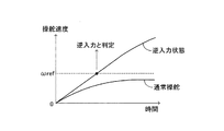
ここで、操舵速度ωに基づいて逆入力状態を判定する原理について説明する。操舵輪Wのタイヤの縁石衝突等により逆入力がステアリング機構10に働くと、操舵輪Wが転舵され、それに伴ってステアリングシャフト12が回転する。このときのステアリングシャフト12の回転速度は、非常に大きく、運転者の操舵操作では回転できない速さとなる。図14は、運転者が操舵ハンドル11を速く回したときの操舵速度の推移と、逆入力が発生したときの操舵速度の推移とを表している。運転者による操舵操作時においては、大きな操舵速度ωは検出されない。そこで、判定基準速度ωrefを運転者による操舵操作では検出されない高速の値に設定しておくことで、逆入力状態を判定することができる。
Here, the principle of determining the reverse input state based on the steering speed ω will be described. When a reverse input is applied to the
逆入力状態判定部110は、操舵速度|ω|が予め設定した判定基準速度ωref以下であれば(S42:No)、ステップS43において、逆入力が発生していないと判定するとともに、逆入力判定フラグFωを0に設定し(Fω=0)、このサブルーチンを抜ける。
If the steering speed | ω | is equal to or lower than the preset determination reference speed ωref (S42: No), the reverse input
一方、操舵速度|ω|が予め設定した判定基準速度ωrefを越えていれば(S42:Yes)、ステップS44において、逆入力が発生していると判定して逆入力判定フラグFωを1に設定し(Fω=1)、このサブルーチンを抜ける。 On the other hand, if the steering speed | ω | exceeds the predetermined determination reference speed ωref (S42: Yes), it is determined in step S44 that reverse input has occurred, and the reverse input determination flag Fω is set to 1. (Fω = 1), and this subroutine is exited.
ステップS43、あるいは、ステップS44において、逆入力判定フラグFωを設定すると、図10のステップS45の処理に移行する。逆入力状態判定部110は、ステップS45において、逆入力判定フラグFωが0であるか否かを判断する。逆入力判定フラグFωが1に設定されている(Fω=1)場合、つまり、操舵速度|ω|に基づいて逆入力状態であると判定されている場合には、ステップS17において、逆入力判定フラグFを1に設定し(F=1)、その逆入力判定フラグFをアシスト電流指令部101に出力する。
If the reverse input determination flag Fω is set in step S43 or step S44, the process proceeds to step S45 in FIG. In step S45, the reverse input
一方、逆入力判定フラグFωが0に設定されている(Fω=0)場合には、ステップS46において、逆入力判定フラグFを0に設定し(F=0)、その逆入力判定フラグFをアシスト電流指令部101に出力する。
On the other hand, if the reverse input determination flag Fω is set to 0 (Fω = 0), the reverse input determination flag F is set to 0 (F = 0) in step S46, and the reverse input determination flag F is set. Output to the assist
逆入力状態判定部110は、ステップS17、あるいは、ステップS46により逆入力判定フラグFを出力すると、本逆入力判定ルーチンを一旦終了する。そして、所定の短い周期で同様の処理を繰り返す。
When the reverse input
以上説明した第2実施形態としての逆入力判定ルーチンを実行する電動パワーステアリング装置によれば、電流差ΔIqだけでなく、操舵トルク|T|、操舵速度|ω|の推移をも考慮した3つの逆入力判定処理を行うため、一層、判定精度が向上する。また、判定処理のうち1つでも逆入力の発生が検出された場合には、衝撃低減用の電流指令を出力するため、ステアリング機構10の衝撃の緩和を遅れることなく一層確実に行うことができる。
According to the electric power steering apparatus that executes the reverse input determination routine according to the second embodiment described above, not only the current difference ΔIq but also three changes taking into account the transition of the steering torque | T | and the steering speed | ω | Since the reverse input determination process is performed, the determination accuracy is further improved. Further, when the occurrence of reverse input is detected in any one of the determination processes, a current command for impact reduction is output, so that the impact of the
尚、逆入力状態の判定に関しては、操舵トルクに基づく逆入力判定処理を省略した構成(ステップS30,S38を省略した構成)、あるいは、操舵速度に基づく逆入力判定処理を省略した構成(ステップS40,S45を省略した構成)を採用することもできる。 Regarding the determination of the reverse input state, a configuration in which the reverse input determination processing based on the steering torque is omitted (a configuration in which steps S30 and S38 are omitted), or a configuration in which the reverse input determination processing based on the steering speed is omitted (step S40). , S45 can be omitted).
また、上記第2実施形態においては、3つの逆入力判定処理(電流差に基づく逆入力判定処理と、操舵トルクに基づく逆入力判定処理と、操舵速度に基づく逆入力判定処理)のうち何れか1つでも逆入力有りと判定されたときに、逆入力状態である旨の判定結果を出力したが、3つの逆入力判定処理のうちの2つあるいは3つで逆入力有りと判定されたときに、逆入力状態である旨の判定結果を出力するようにしてもよい。例えば、電流差に基づく逆入力判定処理と操舵トルクに基づく逆入力判定処理との両方で逆入力有りと判定されたとき(Fi=1、かつ、Ft=1)、逆入力状態である旨の判定結果(F=1)を出力するようにしてもよい。また、電流差に基づく逆入力判定処理と操舵速度に基づく逆入力判定処理との両方で逆入力有りと判定されたとき(Fi=1、かつ、Fω=1)、逆入力状態である旨の判定結果(F=1)を出力するようにしてもよい。また、電流差に基づく逆入力判定処理と操舵トルクに基づく逆入力判定処理と操舵速度に基づく逆入力判定処理の全てにおいて逆入力有りと判定されたとき(Fi=1、かつ、Ft=1、かつ、Fω=1)、逆入力状態である旨の判定結果(F=1)を出力するようにしてもよい。図17は、この3つ目の例について、フローチャートに表したものである。図中において、第2実施形態と同じ処理については、図10のステップ符号と同じステップS符号を使って示している。これによれば、逆入力状態の検出を確実に行うことができる。 In the second embodiment, any one of three reverse input determination processes (a reverse input determination process based on a current difference, a reverse input determination process based on a steering torque, and a reverse input determination process based on a steering speed). When it is determined that at least one reverse input is present, a determination result indicating that it is in the reverse input state is output, but when two or three of the three reverse input determination processes are determined to be reverse input Alternatively, a determination result indicating that the state is the reverse input state may be output. For example, when it is determined that there is a reverse input in both the reverse input determination process based on the current difference and the reverse input determination process based on the steering torque (Fi = 1 and Ft = 1), the reverse input state is indicated. The determination result (F = 1) may be output. Further, when it is determined that there is a reverse input in both the reverse input determination process based on the current difference and the reverse input determination process based on the steering speed (Fi = 1 and Fω = 1), it indicates that the reverse input state is present. The determination result (F = 1) may be output. Further, when it is determined that the reverse input is present in all of the reverse input determination process based on the current difference, the reverse input determination process based on the steering torque, and the reverse input determination process based on the steering speed (Fi = 1, Ft = 1, In addition, Fω = 1), and a determination result (F = 1) indicating that it is in the reverse input state may be output. FIG. 17 is a flowchart showing the third example. In the figure, the same processing as in the second embodiment is indicated by using the same step S code as the step code in FIG. According to this, it is possible to reliably detect the reverse input state.
また、第1、第2実施形態、および、上記第2実施形態の逆入力判定の変形例において、更に、操舵速度ωに基づいて、操舵方向が中立位置から遠ざかる向きとなっているか否かを判定し、操舵方向が中立位置から遠ざかる向きとなっていることを逆入力判定のアンド条件として加えるようにしてもよい。この場合には、逆入力状態の判定精度が更に向上する。 Further, in the first and second embodiments and the modified example of the reverse input determination of the second embodiment, it is further determined whether or not the steering direction is away from the neutral position based on the steering speed ω. It may be determined that the steering direction is away from the neutral position as an AND condition for the reverse input determination. In this case, the determination accuracy of the reverse input state is further improved.
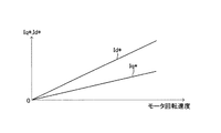
次に、逆入力状態が検出されているときにアシスト電流指令部101が行う衝撃低減用の指令電流の演算処理の変形例について説明する。上述した実施形態においては、逆入力状態が検出されている場合には、衝撃低減用の指令電流としてq軸指令電流Iq*=0、d軸指令電流Id*=Idc(モータロック方向の一定値)に設定したが、例えば、d軸指令電流Id*を一定値にするのではなく、図15に示すように、モータ回転速度に応じて変化するように設定してもよい。モータ回転速度は、操舵速度ωに比例するものであるため、操舵速度検出部107の出力する操舵速度ωに基づいてd軸指令電流Id*を設定すればよい。この例では、モータ回転速度が増加するにしたがって増加するモータロック方向のd軸指令電流Id*が設定される。これによれば、モータ回転速度が速いほど大きなブレーキを発生させることができるため、更に適正な衝撃緩和を行うことができる。
Next, a description will be given of a modification of the calculation process of the command current for impact reduction performed by the assist
また、他の変形例として、図16に示すように、q軸指令電流Iq*についても、モータ回転速度に応じて変化するように設定してもよい。この場合、q軸指令電流Iq*は、モータ回転速度が増加するにしたがって増加する大きさであって、逆入力により電動モータ20が回転してしまう方向とは逆方向のトルクを発生する向きに設定される。これによれば、モータ回転速度が速いほど大きなブレーキを発生させることができるため、更に適正な衝撃緩和を行うことができる。
As another modification, as shown in FIG. 16, the q-axis command current Iq * may be set so as to change according to the motor rotation speed. In this case, the q-axis command current Iq * has a magnitude that increases as the motor rotation speed increases, and in a direction that generates torque in the direction opposite to the direction in which the
また、他の変形例として、逆入力状態が検出されたとき、電動モータ20の3相間(U相、V相、W相)を短絡させることにより、発電によるブレーキを働かせるようにしても良い。例えば、逆入力状態が検出された場合、指令電流id*,iq*の演算を停止して、モータ駆動回路30の上アーム回路のスイッチング素子31,33,35をオン(デューティ比100%)、下アーム回路のスイッチング素子32,34,366をオフ(デューティ比0%)にするPWM制御信号をモータ駆動回路30に出力する。これにより、電動モータ20の3相間が短絡され、逆入力によるロータの回転でモータコイルに発電電流が流れて電動モータ20にブレーキが働く。
As another modification, when a reverse input state is detected, a brake by power generation may be applied by short-circuiting the three phases (U phase, V phase, W phase) of the
以上、本実施形態の電動パワーステアリング装置について説明したが、本発明は上記実施形態に限定されるものではなく、本発明の目的を逸脱しない限りにおいて種々の変更が可能である。 The electric power steering apparatus according to the present embodiment has been described above. However, the present invention is not limited to the above-described embodiment, and various modifications can be made without departing from the object of the present invention.
例えば、本実施形態においては、電動モータ20の回転角を検出する回転角センサ21により操舵角θおよび操舵速度ωを検出するようにしているが、例えば、ステアリングシャフト12に回転角センサを設けて、ステアリングシャフト12の回転角度および回転角速度により操舵角θおよび操舵速度ωを検出する構成でもよい。
For example, in this embodiment, the steering angle θ and the steering speed ω are detected by the
また、本実施形態においては、モータ駆動回路30のスイッチング素子としてMOS−FETを用いているが、他のスイッチング素子を用いることも可能である。また、モータ駆動回路30の入力側に、車載電源装置80から供給される電源を昇圧する昇圧回路を設けて電動モータ20の大出力化を図るようにしてもよい。
In the present embodiment, the MOS-FET is used as the switching element of the
10…ステアリング機構、11…操舵ハンドル、12…ステアリングシャフト、20…電動モータ、21…回転角センサ、22…操舵トルクセンサ、25…車速センサ、30…モータ駆動回路、37…電力供給ライン、38…電流センサ、88…主電源リレー、100…電子制御装置(アシストECU)、101…アシスト電流指令部、102…フィードバック制御部、103…3相/2相変換部、104…回転角変換部、105…3相/2相座標変換部、106…PWM制御信号発生部、107…操舵速度検出部、110…逆入力状態検出部。
DESCRIPTION OF
Claims (3)
操舵ハンドルに連結されたステアリングシャフトに働く捩り力を操舵トルクとして検出する操舵トルク検出手段と、
前記検出した操舵トルクに基づいて目標電流を演算し、演算した目標電流が前記電動モータに流れるように前記電動モータの通電を制御するモータ制御手段と、
タイヤからの逆入力により操舵輪が転舵されてしまう逆入力状態を検出する逆入力状態検出手段と、
前記逆入力状態が検出されたときに、前記ステアリング機構に働く衝撃を低減する衝撃低減手段と
を備えた電動パワーステアリング装置において、
前記逆入力検出手段は、
前記目標電流を表す情報と、前記電動モータに実際に出力された実電流を表す情報とを取得する電流情報取得手段と、
前記取得した情報に基づいて、前記実電流が前記目標電流よりも小さく、その差が判定基準値を超えた場合に、前記逆入力状態であると判定する電流判定手段と
を備えたことを特徴とする電動パワーステアリング装置。 An electric motor provided in the steering mechanism for generating steering assist torque;
A steering torque detecting means for detecting a torsional force acting on a steering shaft connected to the steering handle as a steering torque;
Motor control means for calculating a target current based on the detected steering torque and controlling energization of the electric motor so that the calculated target current flows to the electric motor;
Reverse input state detection means for detecting a reverse input state in which the steered wheels are steered by reverse input from the tire;
An electric power steering apparatus comprising: an impact reducing means for reducing an impact acting on the steering mechanism when the reverse input state is detected;
The reverse input detection means includes
Current information acquisition means for acquiring information representing the target current and information representing the actual current actually output to the electric motor;
A current determination unit that determines that the reverse input state is established when the actual current is smaller than the target current and a difference thereof exceeds a determination reference value based on the acquired information. Electric power steering device.
前記操舵トルク検出手段により検出された操舵トルクを表す情報を取得するトルク情報取得手段と、
前記取得した情報に基づいて、前記操舵トルクが運転者の操舵操作では検出されない大きな値に設定された基準トルクよりも大きな値で基準時間以上継続した場合に、前記逆入力状態であると判定するトルク判定手段と
を備えたことを特徴とする請求項1記載の電動パワーステアリング装置。 The reverse input detection means further includes:
Torque information acquisition means for acquiring information representing the steering torque detected by the steering torque detection means;
Based on the acquired information, when the steering torque continues for a reference time at a value larger than a reference torque set to a large value that is not detected by the driver's steering operation, the reverse input state is determined. The electric power steering apparatus according to claim 1, further comprising: a torque determination unit.
操舵速度を表す情報を取得する操舵速度情報取得手段と、
前記取得した情報から、前記操舵速度が運転者の操舵操作では回転できない高速に設定された基準速度よりも大きい場合に、前記逆入力状態であると判定する速度判定手段と
を備えたことを特徴とする請求項1または2記載の電動パワーステアリング装置。 The reverse input detection means further includes:
Steering speed information acquisition means for acquiring information representing the steering speed;
Speed determining means for determining that the reverse input state is obtained when the steering speed is higher than a reference speed set at a high speed that cannot be rotated by a driver's steering operation from the acquired information. The electric power steering apparatus according to claim 1 or 2.
Priority Applications (1)
| Application Number | Priority Date | Filing Date | Title |
|---|---|---|---|
| JP2008324856A JP5212082B2 (en) | 2008-12-22 | 2008-12-22 | Electric power steering device |
Applications Claiming Priority (1)
| Application Number | Priority Date | Filing Date | Title |
|---|---|---|---|
| JP2008324856A JP5212082B2 (en) | 2008-12-22 | 2008-12-22 | Electric power steering device |
Publications (2)
| Publication Number | Publication Date |
|---|---|
| JP2010143494A true JP2010143494A (en) | 2010-07-01 |
| JP5212082B2 JP5212082B2 (en) | 2013-06-19 |
Family
ID=42564362
Family Applications (1)
| Application Number | Title | Priority Date | Filing Date |
|---|---|---|---|
| JP2008324856A Expired - Fee Related JP5212082B2 (en) | 2008-12-22 | 2008-12-22 | Electric power steering device |
Country Status (1)
| Country | Link |
|---|---|
| JP (1) | JP5212082B2 (en) |
Cited By (4)
| Publication number | Priority date | Publication date | Assignee | Title |
|---|---|---|---|---|
| JP2012240537A (en) * | 2011-05-18 | 2012-12-10 | Jtekt Corp | Electric power steering apparatus |
| JP2013123949A (en) * | 2011-12-13 | 2013-06-24 | Jtekt Corp | Vehicular steering device |
| US9238197B2 (en) | 2010-10-04 | 2016-01-19 | Otsuka Chemical Co., Ltd. | Exhaust gas purification filter, and method for producing same |
| EP3647160A1 (en) * | 2018-10-30 | 2020-05-06 | Jtekt Corporation | Steering control device |
Citations (7)
| Publication number | Priority date | Publication date | Assignee | Title |
|---|---|---|---|---|
| JPH0478770A (en) * | 1990-07-19 | 1992-03-12 | Mazda Motor Corp | Steering device of automobile |
| JPH07228263A (en) * | 1994-02-18 | 1995-08-29 | Toyota Motor Corp | Motor-operated power steering device |
| JP2002274407A (en) * | 2001-03-22 | 2002-09-25 | Koyo Seiko Co Ltd | Electric power steering device |
| JP2004256018A (en) * | 2003-02-26 | 2004-09-16 | Toyoda Mach Works Ltd | Power steering system |
| JP2007062499A (en) * | 2005-08-30 | 2007-03-15 | Jtekt Corp | Electric power steering device |
| JP2007118839A (en) * | 2005-10-31 | 2007-05-17 | Nsk Ltd | Controller of electric power steering device |
| JP2008056224A (en) * | 2006-08-03 | 2008-03-13 | Nsk Ltd | Road surface reaction force detection system of steering device |
-
2008
- 2008-12-22 JP JP2008324856A patent/JP5212082B2/en not_active Expired - Fee Related
Patent Citations (7)
| Publication number | Priority date | Publication date | Assignee | Title |
|---|---|---|---|---|
| JPH0478770A (en) * | 1990-07-19 | 1992-03-12 | Mazda Motor Corp | Steering device of automobile |
| JPH07228263A (en) * | 1994-02-18 | 1995-08-29 | Toyota Motor Corp | Motor-operated power steering device |
| JP2002274407A (en) * | 2001-03-22 | 2002-09-25 | Koyo Seiko Co Ltd | Electric power steering device |
| JP2004256018A (en) * | 2003-02-26 | 2004-09-16 | Toyoda Mach Works Ltd | Power steering system |
| JP2007062499A (en) * | 2005-08-30 | 2007-03-15 | Jtekt Corp | Electric power steering device |
| JP2007118839A (en) * | 2005-10-31 | 2007-05-17 | Nsk Ltd | Controller of electric power steering device |
| JP2008056224A (en) * | 2006-08-03 | 2008-03-13 | Nsk Ltd | Road surface reaction force detection system of steering device |
Cited By (4)
| Publication number | Priority date | Publication date | Assignee | Title |
|---|---|---|---|---|
| US9238197B2 (en) | 2010-10-04 | 2016-01-19 | Otsuka Chemical Co., Ltd. | Exhaust gas purification filter, and method for producing same |
| JP2012240537A (en) * | 2011-05-18 | 2012-12-10 | Jtekt Corp | Electric power steering apparatus |
| JP2013123949A (en) * | 2011-12-13 | 2013-06-24 | Jtekt Corp | Vehicular steering device |
| EP3647160A1 (en) * | 2018-10-30 | 2020-05-06 | Jtekt Corporation | Steering control device |
Also Published As
| Publication number | Publication date |
|---|---|
| JP5212082B2 (en) | 2013-06-19 |
Similar Documents
| Publication | Publication Date | Title |
|---|---|---|
| KR100914424B1 (en) | Electric power steering device, and control method thereof | |
| JP5262931B2 (en) | Electric power steering device | |
| JP4228237B2 (en) | Electric power steering device | |
| JP5365701B2 (en) | Electric power steering device | |
| JP5263090B2 (en) | Electric power steering device | |
| US8272474B2 (en) | Electric power steering system | |
| EP1955928B1 (en) | Motor controller and electric power steering system | |
| JP4715919B2 (en) | Electric power steering device | |
| US7577505B2 (en) | Electric power steering apparatus | |
| JP5212082B2 (en) | Electric power steering device | |
| JP5263079B2 (en) | Electric power steering device | |
| EP3483036B1 (en) | Steering control apparatus | |
| US8981690B2 (en) | Electric power steering system | |
| JP2011218878A (en) | Electric power steering apparatus | |
| EP3854663B1 (en) | Steering control device | |
| JP2010167881A (en) | Steering device of vehicle | |
| JP2010167878A (en) | Electric power steering device | |
| JP2010137627A (en) | Electric power steering device | |
| JP2010167880A (en) | Electric power steering device | |
| JP2018144628A (en) | Electric power steering device | |
| US11167790B2 (en) | Steering control device | |
| JP2010167879A (en) | Steering device of vehicle | |
| JP2019193464A (en) | Steering control device |
Legal Events
| Date | Code | Title | Description |
|---|---|---|---|
| A621 | Written request for application examination |
Free format text: JAPANESE INTERMEDIATE CODE: A621 Effective date: 20110905 |
|
| A977 | Report on retrieval |
Free format text: JAPANESE INTERMEDIATE CODE: A971007 Effective date: 20130121 |
|
| TRDD | Decision of grant or rejection written | ||
| A01 | Written decision to grant a patent or to grant a registration (utility model) |
Free format text: JAPANESE INTERMEDIATE CODE: A01 Effective date: 20130129 |
|
| A61 | First payment of annual fees (during grant procedure) |
Free format text: JAPANESE INTERMEDIATE CODE: A61 Effective date: 20130211 |
|
| R151 | Written notification of patent or utility model registration |
Ref document number: 5212082 Country of ref document: JP Free format text: JAPANESE INTERMEDIATE CODE: R151 |
|
| FPAY | Renewal fee payment (event date is renewal date of database) |
Free format text: PAYMENT UNTIL: 20160308 Year of fee payment: 3 |
|
| LAPS | Cancellation because of no payment of annual fees |