JP2010143219A - Half tone image gloss control for gross mark - Google Patents
Half tone image gloss control for gross mark Download PDFInfo
- Publication number
- JP2010143219A JP2010143219A JP2009282712A JP2009282712A JP2010143219A JP 2010143219 A JP2010143219 A JP 2010143219A JP 2009282712 A JP2009282712 A JP 2009282712A JP 2009282712 A JP2009282712 A JP 2009282712A JP 2010143219 A JP2010143219 A JP 2010143219A
- Authority
- JP
- Japan
- Prior art keywords
- halftone
- orientation
- anisotropic
- image
- gloss
- Prior art date
- Legal status (The legal status is an assumption and is not a legal conclusion. Google has not performed a legal analysis and makes no representation as to the accuracy of the status listed.)
- Pending
Links
Images

Classifications
-
- H—ELECTRICITY
- H04—ELECTRIC COMMUNICATION TECHNIQUE
- H04N—PICTORIAL COMMUNICATION, e.g. TELEVISION
- H04N1/00—Scanning, transmission or reproduction of documents or the like, e.g. facsimile transmission; Details thereof
- H04N1/40—Picture signal circuits
- H04N1/405—Halftoning, i.e. converting the picture signal of a continuous-tone original into a corresponding signal showing only two levels
- H04N1/4055—Halftoning, i.e. converting the picture signal of a continuous-tone original into a corresponding signal showing only two levels producing a clustered dots or a size modulated halftone pattern
- H04N1/4058—Halftoning, i.e. converting the picture signal of a continuous-tone original into a corresponding signal showing only two levels producing a clustered dots or a size modulated halftone pattern with details for producing a halftone screen at an oblique angle
-
- H—ELECTRICITY
- H04—ELECTRIC COMMUNICATION TECHNIQUE
- H04N—PICTORIAL COMMUNICATION, e.g. TELEVISION
- H04N1/00—Scanning, transmission or reproduction of documents or the like, e.g. facsimile transmission; Details thereof
- H04N1/00838—Preventing unauthorised reproduction
- H04N1/00883—Auto-copy-preventive originals, i.e. originals that are designed not to allow faithful reproduction
Abstract
Description
本発明は、一般には、絵画やテキストとなるイメージデータのハードコピーにおいて固有のグロス(光沢)に関する。より詳細には、本発明は、ハーフトーンド(化)イメージデータと、そのハーフトーンイメージデータがハードコピーに印刷されるときの差分グロス(differential gloss)の制御に関する。 The present invention generally relates to a gloss (gloss) specific to a hard copy of image data such as a picture or text. More particularly, the present invention relates to halftoned image data and control of differential gloss when the halftone image data is printed on a hard copy.
文書の複写から保護する方法を持つのが望ましい。内容の一部を人間の読者は容易に確認できるが複写機のスキャナはできない方法が最も望ましい。1つのアプローチは、イメージをクリアトナー若しくはインクを用いて印刷し、紙をある角度で保持することによって人間の読者は見分けることができるが、そのページを直角に読むことに制限されている複写機のスキャナは検出できないような差分を反射光と拡散光に生成するというものである。 It would be desirable to have a way to protect against document copying. A method in which a human reader can easily confirm a part of the contents but a copying machine scanner is not desirable is most desirable. One approach is to copy the image with clear toner or ink and hold the paper at an angle, which can be discerned by the human reader, but is limited to reading the page at right angles This scanner generates a difference between the reflected light and the diffused light that cannot be detected.
読むことはできるがコピーはできないページを印刷できるプリンタが必要とされている。米国特許第4、210、346号や5、695、220号に記述された1つの方法は、異なる角度において異なる拡散光特性を有するようデザインされた特別なホワイトトナーと特別なホワイト紙を用いるものである。勿論、このシステムは、特別な整合する紙とトナーを必要とする。
Hanna等に付与された米国特許第6、108、512号では、開示された発明は、複写不可能なプリントを生成するシステムを開示する。ゼログラフィックプリンタでは、テキストはクリアトナーを用いて印刷される。したがって、ページのトナー部分と非トナー部分(トナーが無い部分)間の光学上の差分だけが反射力(率)に含まれる。プラスチックトナーは、紙より光を反射する。人間の読者は、そのページを、目がトナーからの反射光を遮る角度に保持し、より明るく現れるトナーとより暗く現れる紙の間にコントラストを作り出すことによって読むことができる。しかしながら、複写機のスキャナは、通常、光をある傾斜角で付与して直角で読み出すことにより、反射光を防止するように設定されている。この場合、拡散光はトナー表面についても非トナー表面についてもほぼ等しく、スキャナは差分を何ら検出せず、複写機は原稿を複写することができない。
There is a need for a printer that can print pages that can be read but not copied. One method described in US Pat. Nos. 4,210,346 and 5,695,220 uses special white toner and special white paper designed to have different diffused light characteristics at different angles It is. Of course, this system requires special matching paper and toner.
In US Pat. No. 6,108,512 to Hanna et al., The disclosed invention discloses a system for producing non-replicatable prints. In xerographic printers, text is printed using clear toner. Accordingly, only the optical difference between the toner portion and the non-toner portion (the portion without toner) of the page is included in the reflectivity (rate). Plastic toner reflects light from paper. A human reader can read the page by keeping the eye at an angle that blocks the reflected light from the toner and creating a contrast between the toner that appears brighter and the paper that appears darker. However, a scanner of a copying machine is usually set to prevent reflected light by applying light at a certain tilt angle and reading it at a right angle. In this case, the diffused light is almost the same for both the toner surface and the non-toner surface, the scanner detects no difference, and the copying machine cannot copy the original.
故に、上述したように、特別なトナー/インク、若しくは、紙/基体(サブストレート)、若しくは、特別な取り扱いを必要とすることなく、また、見ることを可能とするために付加的なプリントの重ね合わせ(重畳)を必要とすることなく、グロスマークの操作を可能とし、グロスを制御する装置及び方法が必要とされている。この必要性には、容易には複写されないが何らの助けも受けていない観察者が容易に見分けることができるイメージを生成することが望ましい、ということも含まれる。したがって、固有のグロスの操作のための改良された方法を用いて、上述したこの及び他の欠陥や欠点を解決することが所望される。 Thus, as described above, no special toner / ink, or paper / substrate (substrate), or additional prints to allow viewing without special handling. There is a need for an apparatus and method for controlling gloss that allows manipulation of gloss marks without the need for superposition. This need also includes the desirability of generating an image that is not easily copied but can be easily distinguished by an observer who has not received any help. Accordingly, it would be desirable to solve this and other deficiencies and disadvantages described above using an improved method for inherent gloss manipulation.
本発明は、ハーフトーンイメージにおいて固有かもしれないものとした差分グロスの操作方法に関するものであって、第1異方性構造配向を有する第1ハーフトーンを選択する段階と、前記第1ハーフトーンのものとは異なる第2異方性構造配向を有する第2ハーフトーンを選択する段階とを備える。前記第1ハーフトーンは、前記ハーフトーンイメージの少なくとも一部に適用され、前記第2ハーフトーンは、前記ハーフトーンイメージの残りの部分に適用される。 The present invention relates to a differential gloss manipulation method that may be inherent in a halftone image, comprising: selecting a first halftone having a first anisotropic structure orientation; and the first halftone. Selecting a second halftone having a second anisotropic structural orientation different from that of the first halftone. The first halftone is applied to at least a portion of the halftone image, and the second halftone is applied to the remaining portion of the halftone image.
特に、本発明は、ハーフトーンイメージにおける知覚グロスの操作方法に関するものであって、異方性構造配向を有する第1ハーフトーンを選択する段階と、前記第1ハーフトーンのものとは異なる構造を有する第2ハーフトーンを選択する段階と、前記第1ハーフトーンを前記ハーフトーンイメージの少なくとも幾らかの部分に適用する段階と、前記第2ハーフトーンを前記ハーフトーンイメージの残りの部分に適用する段階とを備える。 In particular, the present invention relates to a method for manipulating perceptual gloss in a halftone image, wherein a step of selecting a first halftone having an anisotropic structure orientation and a structure different from that of the first halftone are described. Selecting a second halftone having, applying the first halftone to at least some portion of the halftone image, and applying the second halftone to the remaining portion of the halftone image. Stages.
本発明はまた、ハーフトーンイメージにおける知覚グロスの操作方法に関するものであって、第1異方性構造配向を有する第1ハーフトーンを選択する段階と、前記第1ハーフトーンのものとは異なる第2異方性構造配向を有する第2ハーフトーンを選択する段階と、前記第1ハーフトーン及び前記第2ハーフトーンの第1ハーフトーンを前記ハーフトーンイメージの少なくとも幾らかの部分に適用する段階と、前記第2ハーフトーンを前記ハーフトーンイメージの他の部分に適用する段階と、前記第3ハーフトーンを前記ハーフトーンイメージの残りの部分に適用する段階を必要とする。 The present invention also relates to a method for manipulating perceptual gloss in a halftone image, wherein the step of selecting a first halftone having a first anisotropic structure orientation is different from that of the first halftone. Selecting a second halftone having a bi-anisotropic structure orientation; and applying the first halftone and the first halftone of the second halftone to at least some portion of the halftone image; Applying the second halftone to the other part of the halftone image and applying the third halftone to the remaining part of the halftone image.
更に、本発明は、ある異方性構造配向を有する第1ハーフトーンと、この第1ハーフトーンとは異なる構造を有した少なくとも1つの付加的なハーフトーンタイプとを備えるハーフトーンイメージに関する。前記第1ハーフトーンは前記ハーフトーンイメージのある部分に適用され、前記少なくとも1つの付加的なハーフトーンタイプは前記ハーフトーンイメージの残りに適用される。 Furthermore, the invention relates to a halftone image comprising a first halftone having an anisotropic structural orientation and at least one additional halftone type having a structure different from the first halftone. The first halftone is applied to a portion of the halftone image and the at least one additional halftone type is applied to the rest of the halftone image.
様々な異方性ハーフトーンドット構造間の固有の知覚差分グロスを適当に利用することによって、特別な紙、又は、特別なトナー若しくはインクを必要とすることなく、その差分グロスを介して知覚グロスの所望の操作やグロスマークの発生を行うことができる。 By appropriately utilizing the inherent perceptual differential gloss between various anisotropic halftone dot structures, the perceptual gloss can be passed through that differential gloss without the need for special paper or special toner or ink. Desired operations and generation of gloss marks can be performed.
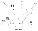
図1は、どのようにして人間の目がページ上のグロスを読むことができ、スキャナは読むことができないかを示す。3つのグロッシー(光沢のある)領域14が示されている。光源2からの光10の1つの光線は、グロストナー14が存在しないポイントで紙に衝突し、その反射光13は、ほんの少量の光があらゆる方向(人間の目1に向かう方向も含む)に存在するように拡散される。等しい強度の光11の他の光線は、グロストナー14が存在するポイントで紙に接触する。ここでは、指示方向において、多量の反射光12が存在する。人間の目1が図示のように位置付けられている場合、人間の目1は、グロッシートナー領域と非グロッシートナー領域との間の大きな差分を容易に確認できる。しかしながら、スキャナ3は、紙に対して直角の入射光だけである。この場合は、グロッシー及び非グロッシードットの双方から来る、ほんの少量の拡散光だけしか存在せず、スキャナは差分を検出することができない。これが、従来の複写機やスキャナによってはスキャンすることができないグロスイメージを生成する1つの方法であるなハーフトーン構造を使用することによって方位角(アジマス)のまわりで入射光が指向性(方向性)(directive)となるよう操作され得るという事実は、ほとんど認識されていなかった。ミラーはミラーの平面に対する光源の方位角に関わらず等しく反射する。同様に、通常の何も書いていない紙(白紙)は、光源の方位角に関わらず、等しく反射し拡散する。しかしながら、印刷物は、ハーフトーンの構造配向に対する光源の原点の方位角に依存して、異なる反射及び拡散特性をしばしば示すことができまた示す。最大化されたときにこのような反射特性は、その性質上異方性である構造を有したハーフトーンで示される。換言すれば、ハーフトーンドットから散乱され、若しくは、反射された光を表現するために使用されるインディカトリックスは、そのハーフトーンが異方性構造(anisotropic structure)を有するときは、光源に対するハーフトーンドットの方位角配向(azimuth orientation)に依存して最大限に変化する。図2は、異方性構造が何を意味するものかの一例である。
FIG. 1 shows how the human eye can read the gloss on the page and the scanner cannot. Three
図2には、異方性の単一のラインスクリーンハーフトーンが、衝突する入射光200に対して2つの配向、即ち、並列配向(parallel orientation)と直角配向(perpendicular orientation)で存在する。双方のハーフトーンドット配向は、紙に対して垂直の角度における拡散光と入射光が等しくなるよう、密度が同様となるように選択される。この方法では、スキャナ3への若しくは人間の目への、真っ直ぐから利用可能な光は同じである。しかしながら、鏡面(正)反射光12は、異方性並列配向210に関してはかなり大きめである。210の並列配向ハーフトーンの大部分が220の直角配向ハーフトーンの大部分に直接に隣接して突き合わされて印刷された場合には、反射光に関して、それらの間に差が存在し、それはある角度から見ると、グロス差分、若しくは、グロスマークにおけるシフトとして知覚される。このグロス差分の知覚(力)は、ハーフトーン異方性配向が図2に示すように90度離れているときに最大となるだろう。
In FIG. 2, an anisotropic single line screen halftone exists in two orientations with respect to impinging incident light 200: a parallel orientation and a perpendicular orientation. Both halftone dot orientations are chosen so that the density is similar so that the diffuse and incident light at an angle perpendicular to the paper is equal. In this way, the light available straight to the scanner 3 or to the human eye is the same. However, the specular (regular) reflected
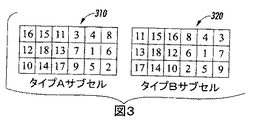
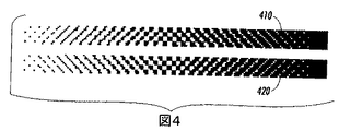
図3は、当業者が本発明の教示を使用する実施形態で使用するのに適したハーフトーンセルの例を示す。これらは当業者には明らかなように単なる有用な一例である。各ハーフトーンセルは、3×6のピクセルアレイとして構成されている。ターンオン/オフ・シーケンスは、数値的に表示されている。ピクセルの番号付けが対角配向(向き)であることに注意していただきたい。タイプAサブセル310とタイプBサブセル320はともに、45度の配向を有し、一方は右に向かうもの、もう一方は左に向かうものである。この配向は、図4の密度スイープ(広がり)410、420にはっきりと示されている。グロス差分の知覚(力)を最大とするため、サブセルタイプAとタイプBの配向は、互いに90度離して配置されている。
FIG. 3 shows an example of a halftone cell suitable for use by those skilled in the art using embodiments of the present invention. These are merely useful examples as will be apparent to those skilled in the art. Each halftone cell is configured as a 3 × 6 pixel array. The turn on / off sequence is numerically displayed. Note that the pixel numbering is a diagonal orientation. Both
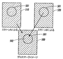
図5は、上述したように、ハーフトーンセルを用いて達成可能なグロスマークイメージ500を示す。スクリーンA510は一方のハーフトーンセルタイプを用い、スクリーンB520はもう一方を用いる。円501は、イメージスクリーン500、510、520の間の視覚面からの理解を助けるものとして設けたものである。所望のグロスマークはここでは、イメージ500の中央で知覚されるべき球502についてのものである。スクリーンA510は、右対角配向とされた異方性ハーフトーンのフィールドを与えるもの、スクリーン520は、左対角配向とされた異方性ハーフトーンセルの球形の領域を与えるものである。この方法で、グロスマークイメージ500を作り出すために、2つのスクリーンタイプの選択がともに寄せ集められる(パッチワークされる)。
FIG. 5 shows a
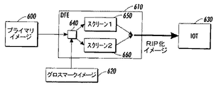
グロスマークイメージの組み立てのための他のアプローチが図6に示されている。ここでは、プライマリイメージ600は、通常と同様に、デジタルフロントエンド(DFE)610に対する入力データとして受け取られる。しかしながら、所望のグロスマークイメージ620は、同様に、DFE610への入力データとしても受け取られる。処理されたイメージは、イメージ出力ターミナル(IOT)630へ伝送される際にはグレイスケール化されており、ハーフトーン密度は、通常と同様に、プライマリイメージ600データによって駆動される。しかしながら、ハーフトーンタイプの選択は、マルチプレクサスイッチ640への入力として、問題のグロスマークイメージデータ620によって駆動される。問題のグロスマークイメージデータ620は、第1異方性構造化ハーフトーンを使用するためにプライマリイメージ600の一部を指示する役割を果たす一方、プライマリイメージ600の残りのために使用されるべき代替のハーフトーンを指示する。当業者によって理解されるように、問題のグロスマークイメージデータ620は、必要ならば、DFE610で、単なる0と1のピクセルデータ表示に平坦化されてもよい。この0と1のパターンはその後、マルチプレクサ640を一方の異方性構造配向タイプ若しくはもう一方へ選択を切り換えるために使用される。マルチプレクサ640はそれ故、所望のグロスマークデータ620によって指図された通りに、スクリーン1タイプハーフトーン650、若しくは、スクリーン2ハーフトーンタイプ660の間で選択の切り換えを行って、IOT630へ送られる際にラスタ入力処理された(RIP)イメージデータ620の複合結果を作り出す。この方法で、パターン620の重ね合わせ(スーパーインポジション)がプライマリイメージ600へ埋め込まれ、それはグロス差分グロスマークとしてのみ知覚され得る。
Another approach for the assembly of the gloss mark image is shown in FIG. Here, the
最後に、2つのハーフトーンタイプ間で交換することにより、各々が同一の整合密度特性を有する一方で別個の異なる異方性構造配向を表示するように慎重に選択された2つのハーフトーンが、特別なトナーや紙を必要とすることなく、グロスマークイメージの重ね合わせを可能とする。グロス差分のこの操作は、勿論、それ自体が固有のグロス特性を最善の方法で表示するようなトナー/インク・基体システムを用いて最善の方法で利用されるだろう。このようなシステムの例としては、静電複写・高級インクジェットシステムがある。ワックスベースのシステムは一般的に固有のグロスを有することはほとんどないが、それらのシステムは、それら固有のグロスを増大させる技術に修正可能なことは明白であろう。このようなシナリオだけで、本明細書の教示は、このようなワックスベースのシステムにも同様に適用することが考えられる。当業者ならば、これらの教示が、カラーイメージや、普通紙、グロッシー紙、若しくはトランスペアレンシー上に加えて、単色の黒及び白の双方に適用されることは理解されよう。また、当業者ならば、固有の異方性グロス差分のこの操作は、ソリッドブラック(ベタ黒)領域(ソリッドトナー/インク)、若しくは、ホワイトのいずれかが存在する場所、従って、トナーが少ない/インクが少ない領域では、弱いことは理解されよう。これが、これらの領域が選択されたハーフトーンの異方性構造を最善には示さない理由である。 Finally, by exchanging between the two halftone types, two halftones carefully selected to display distinct and different anisotropic structural orientations, each having the same matching density characteristics, Gloss mark images can be superimposed without requiring special toner or paper. This manipulation of the gross difference will, of course, be best utilized with a toner / ink substrate system that itself displays the inherent gloss properties in the best possible manner. An example of such a system is an electrostatic copying / high-end inkjet system. Wax-based systems generally have little inherent gloss, but it will be apparent that they can be modified to techniques that increase their inherent gloss. In such a scenario alone, the teachings herein may be equally applicable to such wax-based systems. Those skilled in the art will appreciate that these teachings apply to both monochromatic black and white, in addition to color images, plain paper, glossy paper, or transparency. Also, those skilled in the art will recognize that this manipulation of the intrinsic anisotropic gloss difference is the place where either solid black (solid black) areas (solid toner / ink) or white are present, and therefore less toner / It will be appreciated that in areas where ink is low, it is weak. This is why these regions do not best exhibit the selected halftone anisotropic structure.
本明細書に開示された実施形態は好ましいものではあるが、この教示から、当業者ならば、様々な代替変更、変形、改良をなし得ることが分かるだろう。例えば、当業者ならば、本明細書に挙げた教示は、多くの型のトナー/インクおよび基体タイプに適用できると同時に、多くの型のハーフトーンセルタイプや3つ以上の異なるハーフトーン構造を選択することを含むような構成にも適用できることが分かるだろう。このような全ての変形が請求項に含まれる。 While the embodiments disclosed herein are preferred, from this teaching, one of ordinary skill in the art appreciates that various alternative changes, modifications, and improvements can be made. For example, those skilled in the art will be able to apply the teachings provided herein to many types of toner / ink and substrate types, while simultaneously using many types of halftone cell types and more than two different halftone structures. It will be understood that the present invention can be applied to a configuration including selection. All such variations are within the scope of the claims.
Claims (13)
第1異方性構造配向を有する第1ハーフトーンを選択する段階と、
前記第1ハーフトーンのものとは異なる第2異方性構造配向を有する第2ハーフトーンを選択する段階と、
前記第1ハーフトーンを前記ハーフトーンイメージの少なくとも幾らかの部分に適用する段階と、
前記第2ハーフトーンを前記ハーフトーンイメージの残りの部分に適用する段階と、
を備えることを特徴とする方法。 In the operation method of differential gloss in halftone image,
Selecting a first halftone having a first anisotropic structural orientation;
Selecting a second halftone having a second anisotropic structural orientation different from that of the first halftone;
Applying the first halftone to at least some portion of the halftone image;
Applying the second halftone to the rest of the halftone image;
A method comprising the steps of:
異方性構造配向を有する第1ハーフトーンを選択する段階と、
前記第1ハーフトーンのものとは異なる構造を有する第2ハーフトーンを選択する段階と、
前記第1ハーフトーンを前記ハーフトーンイメージの少なくとも幾らかの部分に適用する段階と、
前記第2ハーフトーンを前記ハーフトーンイメージの残りの部分に適用する段階と、
を備えることを特徴とする方法。 In the operation method of perceptual gloss in a halftone image,
Selecting a first halftone having an anisotropic structural orientation;
Selecting a second halftone having a different structure from that of the first halftone;
Applying the first halftone to at least some portion of the halftone image;
Applying the second halftone to the rest of the halftone image;
A method comprising the steps of:
第1異方性構造配向を有する第1ハーフトーンを選択する段階と、
前記第1ハーフトーンのものとは異なる第2異方性構造配向を有する第2ハーフトーンを選択する段階と、
前記第1ハーフトーン及び前記第2ハーフトーンの双方と異なる構造を有する第3ハーフトーンを選択する段階と、
前記第1ハーフトーンを前記ハーフトーンイメージの少なくとも幾らかの部分に適用する段階と、
前記第2ハーフトーンを前記ハーフトーンイメージの他の部分に適用する段階と、
前記第3ハーフトーンを前記ハーフトーンイメージの残りの部分に適用する段階と、
を備えることを特徴とする方法。 In the operation method of differential gloss in halftone image,
Selecting a first halftone having a first anisotropic structural orientation;
Selecting a second halftone having a second anisotropic structural orientation different from that of the first halftone;
Selecting a third halftone having a different structure from both the first halftone and the second halftone;
Applying the first halftone to at least some portion of the halftone image;
Applying the second halftone to other portions of the halftone image;
Applying the third halftone to the remaining portion of the halftone image;
A method comprising the steps of:
ある異方性構造配向を有する第1ハーフトーンと、
この第1ハーフトーンとは異なる構造を有した少なくとも1つの付加的なハーフトーンタイプとを備え、
前記第1ハーフトーンは前記ハーフトーンイメージのある部分に適用され、前記少なくとも1つの付加的なハーフトーンタイプは前記ハーフトーンイメージの残りに適用されることを特徴とするハーフトーンイメージ。 In the halftone image,
A first halftone having an anisotropic structural orientation;
Comprising at least one additional halftone type having a different structure from the first halftone;
The halftone image wherein the first halftone is applied to a portion of the halftone image and the at least one additional halftone type is applied to the remainder of the halftone image.
Applications Claiming Priority (1)
| Application Number | Priority Date | Filing Date | Title |
|---|---|---|---|
| US10/159,423 US7180635B2 (en) | 2002-05-30 | 2002-05-30 | Halftone image gloss control for glossmarks |
Related Parent Applications (1)
| Application Number | Title | Priority Date | Filing Date |
|---|---|---|---|
| JP2003153961A Division JP4796743B2 (en) | 2002-05-30 | 2003-05-30 | Halftone image gloss control for gloss marks |
Publications (1)
| Publication Number | Publication Date |
|---|---|
| JP2010143219A true JP2010143219A (en) | 2010-07-01 |
Family
ID=29419703
Family Applications (2)
| Application Number | Title | Priority Date | Filing Date |
|---|---|---|---|
| JP2003153961A Expired - Fee Related JP4796743B2 (en) | 2002-05-30 | 2003-05-30 | Halftone image gloss control for gloss marks |
| JP2009282712A Pending JP2010143219A (en) | 2002-05-30 | 2009-12-14 | Half tone image gloss control for gross mark |
Family Applications Before (1)
| Application Number | Title | Priority Date | Filing Date |
|---|---|---|---|
| JP2003153961A Expired - Fee Related JP4796743B2 (en) | 2002-05-30 | 2003-05-30 | Halftone image gloss control for gloss marks |
Country Status (6)
| Country | Link |
|---|---|
| US (1) | US7180635B2 (en) |
| EP (1) | EP1367810B1 (en) |
| JP (2) | JP4796743B2 (en) |
| CA (1) | CA2429446C (en) |
| DE (1) | DE60331022D1 (en) |
| MX (1) | MXPA03004682A (en) |
Families Citing this family (46)
| Publication number | Priority date | Publication date | Assignee | Title |
|---|---|---|---|---|
| US7382495B2 (en) * | 2003-12-12 | 2008-06-03 | Xerox Corporation | Reduction of differential gloss |
| US7352493B2 (en) * | 2003-12-12 | 2008-04-01 | Xerox Corporation | Enhancement of glossmark images at low and high densities |
| US7301675B2 (en) * | 2004-06-29 | 2007-11-27 | Xerox Corporation | Glossmark images with clear toner |
| US7304770B2 (en) * | 2004-08-30 | 2007-12-04 | Xerox Corporation | Reduction of differential gloss with halftoned clear toner |
| US7391537B2 (en) | 2004-09-28 | 2008-06-24 | Xerox Corporation | User interface for differential gloss images |
| US7324241B2 (en) * | 2004-09-29 | 2008-01-29 | Xerox Corporation | Variable data differential gloss images |
| EP1705530A1 (en) * | 2005-03-22 | 2006-09-27 | Eastman Kodak Company | Method and device for controlling differential gloss of low-density areas and print item produced thereby |
| EP1705529A1 (en) | 2005-03-22 | 2006-09-27 | Eastman Kodak Company | Method and device for controlling differential gloss and print item produced thereby |
| US8437044B2 (en) * | 2005-03-22 | 2013-05-07 | Eastman Kodak Company | Method and device for controlling differential gloss and print item produced thereby |
| EP1705531A1 (en) * | 2005-03-22 | 2006-09-27 | Eastman Kodak Company | Method and device for controlling differential gloss of high-density areas and print item produced thereby |
| US7580155B2 (en) * | 2005-12-19 | 2009-08-25 | Xerox Corporation | Tools to embed information into digital visual works |
| US7589865B2 (en) * | 2005-12-21 | 2009-09-15 | Xerox Corporation | Variable differential gloss font image data |
| US7580153B2 (en) * | 2005-12-21 | 2009-08-25 | Xerox Corporation | Printed visible fonts with attendant background |
| US8090141B2 (en) | 2006-01-31 | 2012-01-03 | Xerox Corporation | System and method to automatically establish preferred area for image-wise watermark |
| US8283004B2 (en) * | 2006-05-11 | 2012-10-09 | Xerox Corporation | Substrate fluorescence pattern mask for embedding information in printed documents |
| US8277908B2 (en) * | 2006-05-11 | 2012-10-02 | Xerox Corporation | Substrate fluorescence mask for embedding information in printed documents |
| US8248661B2 (en) * | 2007-02-12 | 2012-08-21 | Xerox Corporation | Color-consistent three level differential gloss images |
| US7639400B2 (en) | 2007-02-13 | 2009-12-29 | Xerox Corporation | Glossmark image simulation with application of background modified gloss effect image |
| US7656556B2 (en) | 2007-02-28 | 2010-02-02 | Xerox Corporation | Detection of a differential gloss region in a cluster-screen halftone image using filters each having a different polarization |
| US8821996B2 (en) * | 2007-05-29 | 2014-09-02 | Xerox Corporation | Substrate fluorescent non-overlapping dot patterns for embedding information in printed documents |
| US8455087B2 (en) * | 2007-06-05 | 2013-06-04 | Xerox Corporation | Infrared encoding of security elements using standard xerographic materials with distraction patterns |
| US8460781B2 (en) * | 2007-06-05 | 2013-06-11 | Xerox Corporation | Infrared encoding of security elements using standard xerographic materials |
| US8269987B2 (en) * | 2007-10-30 | 2012-09-18 | Xerox Corporation | Using application side truetype or other outline fonts to create specialty imaging fonts on digital front-end |
| US8009329B2 (en) * | 2007-11-09 | 2011-08-30 | Xerox Corporation | Fluorescence-based correlation mark for enhanced security in printed documents |
| US7894103B2 (en) * | 2008-02-20 | 2011-02-22 | Xerox Corporation | Variable data digital pantographs |
| US7934785B2 (en) * | 2008-03-18 | 2011-05-03 | Xerox Corporation | Selectable gloss coating system |
| US8345314B2 (en) * | 2008-11-24 | 2013-01-01 | Xerox Corporation | Methods and systems to embed glossmark digital watermarks into continuous-tone images |
| US7869090B2 (en) * | 2008-12-17 | 2011-01-11 | Xerox Corporation | Variable data digital pantographs |
| US8310718B2 (en) | 2009-03-16 | 2012-11-13 | Xerox Corporation | High resolution scalable gloss effect |
| US8179570B2 (en) * | 2009-03-31 | 2012-05-15 | Xerox Corporation | Generating image embedded with UV fluorescent watermark by combining binary images generated using different halftone strategies |
| US9749607B2 (en) | 2009-07-16 | 2017-08-29 | Digimarc Corporation | Coordinated illumination and image signal capture for enhanced signal detection |
| US8619329B2 (en) | 2010-11-12 | 2013-12-31 | Xerox Corporation | Print smoothness on clear toner enabled systems |
| US8608272B2 (en) | 2010-12-03 | 2013-12-17 | Xerox Corporation | System and method for inkjet printing with a differential halftoned protective overcoat with gloss compensation |
| US8941899B2 (en) | 2011-02-22 | 2015-01-27 | Xerox Corporation | Simulated paper texture using glossmark on texture-less stock |
| US8619331B2 (en) * | 2011-07-19 | 2013-12-31 | Xerox Corporation | Simulated paper texture using clear toner and glossmark on texture-less stock |
| US9635378B2 (en) | 2015-03-20 | 2017-04-25 | Digimarc Corporation | Sparse modulation for robust signaling and synchronization |
| US10424038B2 (en) | 2015-03-20 | 2019-09-24 | Digimarc Corporation | Signal encoding outside of guard band region surrounding text characters, including varying encoding strength |
| US9275428B2 (en) | 2014-03-20 | 2016-03-01 | Xerox Corporation | Dark to light watermark without special materials |
| US10783601B1 (en) | 2015-03-20 | 2020-09-22 | Digimarc Corporation | Digital watermarking and signal encoding with activable compositions |
| WO2016153936A1 (en) | 2015-03-20 | 2016-09-29 | Digimarc Corporation | Digital watermarking and data hiding with narrow-band absorption materials |
| US9756212B2 (en) | 2015-11-25 | 2017-09-05 | Xerox Corporation | System and method for producing seesaw gloss effect and recording medium with seesaw gloss effect |
| US9661186B1 (en) * | 2016-06-02 | 2017-05-23 | Xerox Corporation | System and method for rendering gloss effect image patterns on a recording medium |
| US10872392B2 (en) | 2017-11-07 | 2020-12-22 | Digimarc Corporation | Generating artistic designs encoded with robust, machine-readable data |
| US11062108B2 (en) | 2017-11-07 | 2021-07-13 | Digimarc Corporation | Generating and reading optical codes with variable density to adapt for visual quality and reliability |
| US10896307B2 (en) | 2017-11-07 | 2021-01-19 | Digimarc Corporation | Generating and reading optical codes with variable density to adapt for visual quality and reliability |
| US11829655B1 (en) | 2022-10-14 | 2023-11-28 | Xerox Corporation | Method for generating document with specialty imaging and computing device associated therewith |
Citations (1)
| Publication number | Priority date | Publication date | Assignee | Title |
|---|---|---|---|---|
| JPS5619273B2 (en) * | 1972-07-06 | 1981-05-06 |
Family Cites Families (25)
| Publication number | Priority date | Publication date | Assignee | Title |
|---|---|---|---|---|
| US3675948A (en) | 1969-09-10 | 1972-07-11 | American Bank Note Co | Printing method and article for hiding halftone images |
| US4310180A (en) | 1977-05-18 | 1982-01-12 | Burroughs Corporation | Protected document and method of making same |
| US4210346A (en) | 1977-06-23 | 1980-07-01 | Burroughs Corporation | Protected document bearing watermark and method of making |
| US4149194A (en) | 1977-07-07 | 1979-04-10 | Xerox Corporation | Variable angle electronic halftone screening |
| GB2040224A (en) | 1979-01-23 | 1980-08-28 | Alasia Alfred Victor | Security documents |
| CH672687A5 (en) | 1987-11-20 | 1989-12-15 | Lipatec Ets | |
| FI80405C (en) | 1988-03-24 | 1990-06-11 | Suomen Pankin Setelipaino | Printed article secured with warning figure and method for its cutting |
| US5583660A (en) | 1990-09-14 | 1996-12-10 | Minnesota Mining And Manufacturing Company | Non-perpendicular, equal frequency non-conventional screen patterns for electronic halftone generation |
| US5487567A (en) | 1992-04-24 | 1996-01-30 | Francois-Charles Oberthur Group | Printing method and copy-evident secure document |
| US5344192A (en) | 1993-04-01 | 1994-09-06 | Phillips George K | Visual validation mark for bank checks and other security documents |
| JP3241157B2 (en) | 1993-04-19 | 2001-12-25 | 富士写真フイルム株式会社 | Dot image data correction method and image processing apparatus having correction function |
| US5853197A (en) | 1996-03-05 | 1998-12-29 | The Standard Register Company | Security document |
| US5788285A (en) | 1996-06-13 | 1998-08-04 | Wicker; Thomas M. | Document protection methods and products |
| US5678133A (en) | 1996-07-01 | 1997-10-14 | Xerox Corporation | Auto-gloss selection feature for color image output terminals (IOTs) |
| US5734752A (en) | 1996-09-24 | 1998-03-31 | Xerox Corporation | Digital watermarking using stochastic screen patterns |
| US6606168B1 (en) * | 1999-03-31 | 2003-08-12 | 3M Innovative Properties Company | Narrow band, anisotropic stochastic halftone patterns and methods of creating and using the same |
| US6906825B1 (en) * | 1999-06-14 | 2005-06-14 | Toshiba Tec Kabushiki Kaisha | Image processor and color image processor |
| US6714320B1 (en) * | 1999-06-14 | 2004-03-30 | Toshiba Tec Kabushiki Kaisha | Image processor and color image processor |
| US6108512A (en) | 1999-11-29 | 2000-08-22 | Xerox Corporation | Copy prevention method |
| US7148999B2 (en) * | 2002-06-27 | 2006-12-12 | Xerox Corporation | Variable glossmark |
| US7126721B2 (en) * | 2002-06-27 | 2006-10-24 | Xerox Corporation | Protecting printed items intended for public exchange with glossmarks |
| US7193751B2 (en) * | 2002-12-12 | 2007-03-20 | Xerox Corporation | Tag control for runtime glossmarks |
| US7352493B2 (en) * | 2003-12-12 | 2008-04-01 | Xerox Corporation | Enhancement of glossmark images at low and high densities |
| US7301675B2 (en) * | 2004-06-29 | 2007-11-27 | Xerox Corporation | Glossmark images with clear toner |
| US7324241B2 (en) * | 2004-09-29 | 2008-01-29 | Xerox Corporation | Variable data differential gloss images |
-
2002
- 2002-05-30 US US10/159,423 patent/US7180635B2/en active Active
-
2003
- 2003-05-23 CA CA002429446A patent/CA2429446C/en not_active Expired - Fee Related
- 2003-05-27 EP EP03011924A patent/EP1367810B1/en not_active Expired - Fee Related
- 2003-05-27 MX MXPA03004682A patent/MXPA03004682A/en active IP Right Grant
- 2003-05-27 DE DE60331022T patent/DE60331022D1/en not_active Expired - Lifetime
- 2003-05-30 JP JP2003153961A patent/JP4796743B2/en not_active Expired - Fee Related
-
2009
- 2009-12-14 JP JP2009282712A patent/JP2010143219A/en active Pending
Patent Citations (1)
| Publication number | Priority date | Publication date | Assignee | Title |
|---|---|---|---|---|
| JPS5619273B2 (en) * | 1972-07-06 | 1981-05-06 |
Also Published As
| Publication number | Publication date |
|---|---|
| CA2429446A1 (en) | 2003-11-30 |
| DE60331022D1 (en) | 2010-03-11 |
| EP1367810B1 (en) | 2010-01-20 |
| MXPA03004682A (en) | 2005-10-04 |
| US20030231349A1 (en) | 2003-12-18 |
| EP1367810A3 (en) | 2006-06-07 |
| CA2429446C (en) | 2008-09-02 |
| JP2004058655A (en) | 2004-02-26 |
| JP4796743B2 (en) | 2011-10-19 |
| EP1367810A2 (en) | 2003-12-03 |
| US7180635B2 (en) | 2007-02-20 |
Similar Documents
| Publication | Publication Date | Title |
|---|---|---|
| JP4796743B2 (en) | Halftone image gloss control for gloss marks | |
| JP4988019B2 (en) | Tag control for run-time gross marks | |
| EP1370062B1 (en) | Application of glossmarks for printing on ordinary image reproducers | |
| EP1612622B1 (en) | Glossmark images with clear toner | |
| US7813006B2 (en) | Enhancement of glossmark images at low and high densities with selective application of clear toner | |
| US7148999B2 (en) | Variable glossmark | |
| EP1641240B1 (en) | A user interface for differential gloss images | |
| JP4545669B2 (en) | Variable data differential gloss image control method | |
| US7580153B2 (en) | Printed visible fonts with attendant background |
Legal Events
| Date | Code | Title | Description |
|---|---|---|---|
| A131 | Notification of reasons for refusal |
Free format text: JAPANESE INTERMEDIATE CODE: A131 Effective date: 20100610 |
|
| A521 | Written amendment |
Free format text: JAPANESE INTERMEDIATE CODE: A523 Effective date: 20100825 |
|
| A02 | Decision of refusal |
Free format text: JAPANESE INTERMEDIATE CODE: A02 Effective date: 20101007 |