JP2010143056A - Image forming apparatus - Google Patents
Image forming apparatus Download PDFInfo
- Publication number
- JP2010143056A JP2010143056A JP2008322236A JP2008322236A JP2010143056A JP 2010143056 A JP2010143056 A JP 2010143056A JP 2008322236 A JP2008322236 A JP 2008322236A JP 2008322236 A JP2008322236 A JP 2008322236A JP 2010143056 A JP2010143056 A JP 2010143056A
- Authority
- JP
- Japan
- Prior art keywords
- acoustic lens
- electrode
- lens
- acoustic
- image forming
- Prior art date
- Legal status (The legal status is an assumption and is not a legal conclusion. Google has not performed a legal analysis and makes no representation as to the accuracy of the status listed.)
- Pending
Links
Images


Abstract
Description
本発明は、音響レンズを用いた音響インクジェット式記録装置(音響インクジェットプリンタ)に用いられる画像形成装置に関する。 The present invention relates to an image forming apparatus used in an acoustic ink jet recording apparatus (acoustic ink jet printer) using an acoustic lens.
従来からインクジェットプリンタとして、種々の構造をもつものが知られている。
例えばピエゾ方式やサーマル方式のインクジェット方式が従来から提案されている。しかし、これらの方式では、ノズルの目詰まりが発生しやすく印字不良の発生頻度が高いという問題があった。また、ピエゾ方式では、複雑なオリフィス構造を形成する必要があり、コストが高くなっていた。さらに、サーマル方式では、ヘッド部でのヒーターによる加熱が必要なので、インクの熱対策が必要となりインク選択の範囲が狭くなる不具合が生じていた。また、インク液滴サイズを可変することも不可能であった。
Conventionally, ink jet printers having various structures are known.
For example, a piezo method and a thermal ink jet method have been proposed. However, these methods have a problem that nozzles are easily clogged and the frequency of occurrence of printing defects is high. Further, in the piezo method, it is necessary to form a complicated orifice structure, which increases the cost. Furthermore, in the thermal method, since heating with a heater in the head portion is necessary, a countermeasure against ink heat is required, and there is a problem that the range of ink selection is narrowed. Further, it is impossible to change the ink droplet size.
これらの不具合を解決し得るものとして、例えば音響波発生手段を用い、該手段からの音波を集束させてインク液滴を飛翔させて記録紙等に記録印字を行う音響インクジェットプリンタも従来から知られている(例えば、特許文献1参照)。 Conventionally known acoustic inkjet printers that can solve these problems include, for example, acoustic wave generating means, and by focusing sound waves from the means and causing ink droplets to fly to record and print on recording paper or the like. (For example, refer to Patent Document 1).
ところで、上述した音響インクジェットプリンタにおいて、たとえば製造ミス等が生じた際に、インク液滴の飛翔方向にばらつきが生じることがある。このような飛翔方向のばらつきは、印字品質を確保するうえで問題であり、何らかの対策を講じることが望まれている。 By the way, in the above-described acoustic ink jet printer, for example, when a manufacturing error or the like occurs, variation may occur in the flying direction of the ink droplets. Such variation in the flying direction is a problem in ensuring print quality, and it is desired to take some measures.
本発明はこのような事情に鑑みてなされたものであり、音響レンズの焦点位置を変更可能とし、インク飛翔方向を変更できる画像形成装置を得ることを目的とする。 The present invention has been made in view of such circumstances, and an object of the present invention is to obtain an image forming apparatus that can change the focal position of an acoustic lens and change the ink flying direction.
このような目的に応えるために本発明に係る画像形成装置は、音響インクジェット方式の画像形成装置において、超音波収束のための音響レンズと、この音響レンズを駆動する電極とを備え、前記音響レンズとして、流体レンズを使用するとともに、該音響レンズの電極を複数に分割し、異なる駆動を与えることにより、レンズの焦点位置を変更可能とし、インクの飛翔方向を可変にするように構成したことを特徴とする。 In order to meet such an object, an image forming apparatus according to the present invention is an acoustic ink jet image forming apparatus, and includes an acoustic lens for converging ultrasonic waves and an electrode for driving the acoustic lens. As described above, the configuration is such that the fluid lens is used, the electrode of the acoustic lens is divided into a plurality of parts, and a different driving is applied to change the focal position of the lens and the flying direction of the ink is variable. Features.
また、本発明に係る画像形成装置は、音響レンズを用いた音響インクジェット方式の画像形成装置において、超音波収束のための音響レンズと、該音響レンズを駆動する電極とを備え、前記音響レンズを流体レンズで形成するとともに、該音響レンズの電極を複数に分割された構成にすることにより、音響レンズの焦点位置を変更可能とし、インク飛翔方向を変更するように構成したことを特徴とする。 The image forming apparatus according to the present invention is an acoustic ink jet type image forming apparatus using an acoustic lens, and includes an acoustic lens for focusing ultrasonic waves and an electrode for driving the acoustic lens, In addition to being formed of a fluid lens and having a configuration in which the electrode of the acoustic lens is divided into a plurality of parts, the focal position of the acoustic lens can be changed and the ink flying direction is changed.
以上説明したように本発明に係る画像形成装置によれば、インクの飛翔角度を変更することが出来るので、製造ミスにより飛翔位置がずれた場合にも補正をすることが可能になる。 As described above, according to the image forming apparatus of the present invention, the flying angle of ink can be changed, so that it is possible to correct even when the flying position is shifted due to a manufacturing error.
また、電極部の配置を主走査方向にした場合に、レジストレーション補正と供に記録密度の向上も可能になる。 Further, when the electrode portions are arranged in the main scanning direction, recording density can be improved together with registration correction.
図1ないし図5は本発明に係る画像形成装置の一実施形態を示すものであり、これらの図において、本発明の画像形成装置は、音響インクジェット記録方式によるものであって、インクを記録紙へ選択的に飛翔させて、記録パターンを記録紙上に作成するようになっている。 1 to 5 show one embodiment of an image forming apparatus according to the present invention. In these drawings, the image forming apparatus according to the present invention is based on an acoustic ink jet recording system, and ink is used for recording paper. The recording pattern is created on the recording paper by selectively flying.
その模式的断面図を図1に示す。
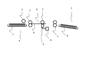
これを簡単に説明すると、この画像形成装置は、大きく分けて給紙部A、記録部B、排紙部Cで構成されている。
給紙部Aは、給紙カセット1、給紙ローラー2で構成され、不図示の中央演算装置から送られて来る給紙データに応じて記録部Bへ用紙Pを供給する。
A schematic cross-sectional view thereof is shown in FIG.
This will be briefly described. This image forming apparatus is roughly composed of a paper feeding unit A, a recording unit B, and a paper discharge unit C.
The paper feeding unit A includes a
記録部Bは、搬送ローラーA3、搬送ローラーB7、プラテンローラー4、記録ヘッド5で構成されている。記録ヘッド5はライン型を採用する。記録ヘッド5には、インクタンク6が接続されている。
The recording unit B includes a conveyance roller A3, a conveyance roller B7, a
印字データに応じて記録ヘッド5からインクIが用紙Pへ向けて飛翔し、記録が行われる。必要に応じてインクタンク6からインクが記録ヘッド5へ供給される。記録部Bで記録が完了した用紙Pは、搬送ローラーB7の回転により排紙部Cへ向かう。排紙部Cでは、記録が完了した用紙Pを排紙カセット8にスタックする。
Ink I flies from the
記録ヘッド5の構成を図2、図3、図4、図5に示す。
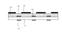
記録ヘッド5は、図2に示すように、ガラス基板9に形成された振動子14と、該振動子14に対応してガラス基板9を介してインク層10側に配置された音響レンズ13と、上部プレート12で構成され、上部プレート12には開口部11が形成されている。
The configuration of the
As shown in FIG. 2, the
本画像形成装置は、音響インクジェット方式であり、振動子14で発生した超音波がガラス基板9を伝播し、音響レンズ13で集束され、インク層10中のインクを上部プレート12の開口部11から選択的に飛翔させる。ここで、開口部11は、飛翔インク滴サイズよりも十分に広く、インク滴サイズを制御する機能は持っていない。
また、従来のサーマル方式やピエゾ型インクジェットでは、ノズル径がΦ20μm前途と非常に小さく目詰まりしやすかったが、本発明では、開口部11は、Φ50μm程度と従来よりもかなり大きくなっており、インク目詰まりの問題も発生しない。
This image forming apparatus is an acoustic ink jet system, and the ultrasonic wave generated by the
Further, in the conventional thermal method and piezo type ink jet, the nozzle diameter is very small as Φ20 μm ahead and easily clogged. There is no clogging problem.
図3、図4、図5により、振動子14と音響レンズ13の構成を以下に説明する。
図3(a)に示すように、振動子14は、共通電極17、圧電体16、セグメント電極15とで構成される。圧電体16は、Zno,Pzt等で構成される。印字データに応じて共通電極17、セグメント電極15に印加される電界によって、圧電体16は振動し超音波を発生する。
The configuration of the
As shown in FIG. 3A, the
例えば、圧電体16に6μm厚のPzt膜を使用した場合、250Mhz、Vp-p 20VのAC電界で駆動する。そして、発生した超音波は、ガラス基板9を介して音響レンズ13で集束される。
For example, when a Pzt film having a thickness of 6 μm is used for the
音響レンズ13は、エレクトロウエッティングを使用した液体レンズである。
音響レンズ13は、図3(a)に示すように、円筒状の形状をしており、内部には、導電性の水性溶媒と非導電性のオイル2種類の溶媒が入れられており、2種類の溶媒の界面がレンズとしての機能を有する。
The
As shown in FIG. 3A, the
音響レンズ13の電極は、図3(b)に示すように半円状に2分割されて配置される。
図5(a)と図5(b)に音響レンズ14の配置図を示す。
すなわち、図5(a)は、振動子16側から見た図であるが、セグメント電極15と共通電極17の交点部に音響レンズ14の中心となるように配置される。また、図5(b)は、音響レンズ13側から見た配置図である。音響レンズ13内の電極部A26、電極部B27は、図5(b)に示すように、主走査方向を中心にして副走査側に向かい合うように配置される。
As shown in FIG. 3B, the electrodes of the
FIG. 5A and FIG. 5B show arrangement views of the
That is, FIG. 5A is a view from the
音響レンズ13は、電極部A26を構成する電極Aa18−1,電極Ba21−1、絶縁体A19−1,20−1、電極部B27を構成する電極Ab18−2,電極Bb21−2、絶縁体B19−2,20−2、ガラス板22で構成されており、インクが内部に入らないように密閉されている。音響レンズ13内部は、ガラス基板9上以外、撥水処理されている。
The
電極Aa18−1,電極Ba21−1には、電源装置A23−1が、電極Ab18−2,電極Bb21−2には、電源装置B23−2が接続されている。
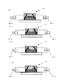
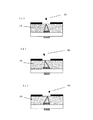
電源装置A23−1および電源装置B23−2から電圧が印加されていないと、音響レンズ13内部の液体の状態は内部が撥水処理をされているので、オイル系溶媒24が壁面を濡らしていくと、図4(a)に示すような状態になる。
The power supply device A23-1 is connected to the electrode Aa18-1 and the electrode Ba21-1, and the power supply device B23-2 is connected to the electrode Ab18-2 and the electrode Bb21-2.
If no voltage is applied from the power supply device A 23-1 and the power supply device B 23-2, the liquid state inside the
電源装置A23−1及び電源装置B23−2から電圧が印加されると、音響レンズ13内部の濡れ性が変化するので水溶性溶媒25が濡らして行き、図4(b)のように界面が凹レンズ形状を形成する。
When a voltage is applied from the power supply device A 23-1 and the power supply device B 23-2, the wettability inside the
また、電源装置A23−1または電源装置B23−2のどちらからのみ電圧が印加されると、図4(c)または図4(d)に示すように、凹型レンズ形状を傾けることが可能になる。電源装置A23−1および電源装置B23−2から印加される電圧を調整することにより、音響レンズの焦点を変化させることが可能になるので、飛翔方向を変更することが可能になる。 Further, when a voltage is applied only from either the power supply device A 23-1 or the power supply device B 23-2, the concave lens shape can be tilted as shown in FIG. 4 (c) or FIG. 4 (d). . Since the focal point of the acoustic lens can be changed by adjusting the voltages applied from the power supply device A 23-1 and the power supply device B 23-2, the flight direction can be changed.
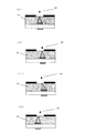
通常の印字パターン時には、図6(a)に示すように開口部11のインク表面に超音波が集束するように調整されている。集束した超音波によりメニスカスが形成され、インク液滴30の飛翔を行い、印字を完成させることが出来る。
In a normal printing pattern, adjustment is made so that the ultrasonic wave is focused on the ink surface of the
たとえば、図5(c)に示すように記録ヘッド5の製造ミス等により共通電極17とセグメント電極15の交点である超音波発生位置が本来のあるべき位置とずれてしまった場合、図6(b)に示すように開口部11からインクを飛翔させることは可能になるが、本来のあるべき位置とは異なった位置にインクを飛翔させることになり、印字不良の原因となっていた。
For example, as shown in FIG. 5C, when the ultrasonic generation position that is the intersection of the
本発明では、音響レンズ13の焦点位置をずらすことが可能なので、図6(c)、図6(d)に示すように、超音波発生位置が本来配置されるべき位置からずれても電源装置A23−1及び電源装置B23−2から印加する電圧を調整することにより、音響レンズ13の焦点位置を移動させることによりインク飛翔角度を変更できるので、インクを本来の位置に飛翔させることが可能になり、レジストレーション補正が容易に行うことが可能になるので高品位な画像を得ることが可能になる。
また、主走査方向に電極部をレイアウトすれば、図7(a),(b),(c)に示すように主走査方向にインク飛翔角度を変更することが可能になる。この場合、レジストレーション補正と供に記録密度の向上が可能になる。
In the present invention, since the focal position of the
If the electrode portions are laid out in the main scanning direction, the ink flying angle can be changed in the main scanning direction as shown in FIGS. 7 (a), (b), and (c). In this case, recording density can be improved together with registration correction.
なお、本発明は上述した実施の形態で説明した構造には限定されず、画像形成装置を構成する各部の形状、構造等を適宜変形、変更し得ることはいうまでもない。 Note that the present invention is not limited to the structure described in the above-described embodiment, and it goes without saying that the shape, structure, and the like of each part constituting the image forming apparatus can be appropriately modified and changed.
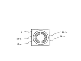
すなわち、上述した実施形態では、音響レンズ13内の電極を2分割した場合を説明したが、本発明はこれに限定されず、4分割など、適宜の数で分割してもよいことはいうまでもない。たとえば図8に示すように、音響レンズ13内の電極を、図中符号26−a,26−b、27−a,27−b等で示すように4分割した場合、レンズの焦点位置を、さらに細かく調節出来るので、インク液滴30のより細かい飛翔方向の補正が可能になるものである。
That is, in the above-described embodiment, the case where the electrode in the
1…給紙カセット、2…給紙ローラー、3…搬送ローラーA、4…プラテンローラー、5…記録ヘッド、6…インクタンク、7…搬送ローラーB、8…排紙カセット、9…ガラス基板、10…インク層、11…開口部、12…上部プレート、13…音響レンズ、14…振動子、15…セグメント電極、16…圧電体、17…共通電極、18−1…電極Aa、18−2…電極Ab、19−1…絶縁体A、19−2…絶縁体B、20−1…絶縁体A、20−2…絶縁体B、21−1…電極Ba、21−2…電極Bb、22…ガラス板、23−1…電源装置A、23−2…電源装置B、24…オイル系溶媒、25…水系溶媒、26…電極部A、27…電極部B、30…インク液滴、P…用紙、A…給紙部、B…記録部、C…排紙部。
DESCRIPTION OF
Claims (2)
超音波収束のための音響レンズと、
この音響レンズを駆動する電極とを備え、
前記音響レンズとして、流体レンズを使用するとともに、
該音響レンズの電極を複数に分割し、異なる駆動を与えることにより、レンズの焦点位置を変更可能とし、インクの飛翔方向を可変にするように構成したことを特徴とする画像形成装置。 In an acoustic inkjet type image forming apparatus,
An acoustic lens for ultrasound convergence;
An electrode for driving the acoustic lens,
While using a fluid lens as the acoustic lens,
An image forming apparatus configured to divide an electrode of the acoustic lens into a plurality of parts and apply different driving to change a focal position of the lens and to change an ink flying direction.
超音波収束のための音響レンズと、
該音響レンズを駆動する電極とを備え、
前記音響レンズを流体レンズで形成するとともに、
該音響レンズの電極を複数に分割された構成にすることにより、音響レンズの焦点位置を変更可能とし、インク飛翔方向を変更するように構成したことを特徴とする画像形成装置。 In an acoustic ink jet image forming apparatus using an acoustic lens,
An acoustic lens for ultrasound convergence;
An electrode for driving the acoustic lens,
Forming the acoustic lens with a fluid lens;
An image forming apparatus characterized in that the focal position of the acoustic lens can be changed by changing the electrode of the acoustic lens into a plurality of parts, and the ink flying direction is changed.
Priority Applications (1)
| Application Number | Priority Date | Filing Date | Title |
|---|---|---|---|
| JP2008322236A JP2010143056A (en) | 2008-12-18 | 2008-12-18 | Image forming apparatus |
Applications Claiming Priority (1)
| Application Number | Priority Date | Filing Date | Title |
|---|---|---|---|
| JP2008322236A JP2010143056A (en) | 2008-12-18 | 2008-12-18 | Image forming apparatus |
Publications (1)
| Publication Number | Publication Date |
|---|---|
| JP2010143056A true JP2010143056A (en) | 2010-07-01 |
Family
ID=42563987
Family Applications (1)
| Application Number | Title | Priority Date | Filing Date |
|---|---|---|---|
| JP2008322236A Pending JP2010143056A (en) | 2008-12-18 | 2008-12-18 | Image forming apparatus |
Country Status (1)
| Country | Link |
|---|---|
| JP (1) | JP2010143056A (en) |
-
2008
- 2008-12-18 JP JP2008322236A patent/JP2010143056A/en active Pending
Similar Documents
| Publication | Publication Date | Title |
|---|---|---|
| US7455393B2 (en) | Mist spraying apparatus and method, and image forming apparatus | |
| US20080129772A1 (en) | Apparatus and method of preventing drying of ink in inkjet printhead and printing method using inkjet printer | |
| US20090244173A1 (en) | Nozzle plate, liquid ejection head and image forming apparatus | |
| JP2012256756A (en) | Formation method of electromechanical conversion film, electromechanical conversion film, electromechanical conversion element, liquid discharge head and image forming apparatus | |
| US7758159B2 (en) | Mist spraying apparatus and image forming apparatus | |
| JP2010208204A (en) | Liquid discharge head, method for manufacturing liquid discharge head and image forming apparatus | |
| JP2005035282A (en) | Actuator device, liquid jetting head and its production method, and liquid jetting device | |
| JP4972949B2 (en) | Droplet ejector | |
| JP2010052316A (en) | Image forming apparatus | |
| JP2010143056A (en) | Image forming apparatus | |
| JPH1044398A (en) | Ink jet recording head and ink jet recorder | |
| JP3384958B2 (en) | Ink jet recording apparatus and manufacturing method thereof | |
| US7611230B2 (en) | Inkjet recording apparatus | |
| US7533966B2 (en) | Mist spraying apparatus and method, and image forming apparatus | |
| JP5017397B2 (en) | Ink jet apparatus and ink coating method | |
| JP5336892B2 (en) | Acoustic ink applicator | |
| WO2024004996A1 (en) | Liquid discharge head and liquid discharge device | |
| JP2006289971A (en) | Mist spraying device and image forming apparatus | |
| JP2004261998A (en) | Ink-jet printer | |
| JP2010167745A (en) | Image forming apparatus | |
| US7497556B2 (en) | Mist spraying apparatus and image forming apparatus | |
| JP2003211666A (en) | Ink jet head, ink jet recorder, and combined machine | |
| JP2016115702A (en) | Piezoelectric actuator, method for manufacturing the same, inkjet head, and inkjet printer | |
| JP2010052315A (en) | Image forming apparatus | |
| JP2009226807A (en) | Inkjet print head |