JP2010143047A - Method for manufacturing precast beam and jig for producing precast beam - Google Patents
Method for manufacturing precast beam and jig for producing precast beam Download PDFInfo
- Publication number
- JP2010143047A JP2010143047A JP2008322109A JP2008322109A JP2010143047A JP 2010143047 A JP2010143047 A JP 2010143047A JP 2008322109 A JP2008322109 A JP 2008322109A JP 2008322109 A JP2008322109 A JP 2008322109A JP 2010143047 A JP2010143047 A JP 2010143047A
- Authority
- JP
- Japan
- Prior art keywords
- coupler
- screw
- axis
- precast beam
- reinforcing bar
- Prior art date
- Legal status (The legal status is an assumption and is not a legal conclusion. Google has not performed a legal analysis and makes no representation as to the accuracy of the status listed.)
- Granted
Links
Images


Landscapes
- Manufacturing Of Tubular Articles Or Embedded Moulded Articles (AREA)
Abstract
【課題】プレキャスト梁を製造する際、ネジ節鉄筋の一端部を型枠に位置決め保持するとともにネジ節鉄筋のネジ山の一端の軸心回りの位置を設定することで、建設現場におけるプレキャスト梁の設置位置に応じて、対となる2本のネジ節鉄筋のネジ位相を合わせることができる、プレキャスト梁の製造に関する技術を提供する。
【解決手段】 複数のネジ節鉄筋41を型枠に対してセットする際、先ず、各ネジ節鉄筋41の一端部にキャップ状のカプラー51を外嵌螺合させ、このカプラー51の端壁61にネジ節鉄筋41の一端が当接して押圧可能にカプラー51を装着し、カプラー51の軸心C1に対してネジ節鉄筋41の一端部の軸心C2を調芯した状態で、カプラー51を介してネジ節鉄筋41の一端部を型枠に位置決め保持するとともにネジ節鉄筋41のネジ山41aの一端の軸心回りの位置を設定する。
【選択図】 図10An object of the present invention is to manufacture a precast beam by positioning and holding one end of a screw joint reinforcing bar on a formwork and setting a position around an axis of one end of a screw thread of the screw joint reinforcing bar. Provided is a technique related to the manufacture of a precast beam, which can match the screw phases of two threaded reinforcing bars to be paired according to the installation position.
When setting a plurality of screw joint reinforcing bars 41 to a mold, first, a cap-shaped coupler 51 is externally screwed to one end of each screw joint reinforcing bar 41, and an end wall 61 of the coupler 51 is fitted. The coupler 51 is mounted so that one end of the screw rebar 41 abuts against the shaft C1 and can be pressed, and the coupler 51 is aligned with the axis C2 of one end of the screw rebar 41 aligned with the axis C1 of the coupler 51. Then, one end of the screw rebar 41 is positioned and held in the mold, and the position around the axis of one end of the thread 41a of the screw rebar 41 is set.
[Selection] Figure 10
Description
本発明は、複数のネジ節鉄筋を型枠に対して所定位置にセットした後に型枠内にコンクリートを打設してプレキャスト梁を製造する際、ネジ節鉄筋の一端部を型枠に位置決め保持するとともにネジ節鉄筋のネジ山の一端の軸心回りの位置を設定することができる技術に関するものである。 In the present invention, when a plurality of screw rebars are set in a predetermined position with respect to a formwork and concrete is placed in the formwork to manufacture a precast beam, one end of the screw joint rebar is positioned and held in the formwork. In addition, the present invention relates to a technique capable of setting a position around an axial center of one end of a thread of a screw rebar.
近年、建築物(特に、多階建築物)を建設する場合に、工期短縮を図るために、工場において、柱、梁、壁、床(天井)等のプレキャストコンクリート(PC)を個別に製造し、そのプレキャストコンクリートを建設現場に搬送し、その建設現場で設置して組み立てる、所謂プレキャスト工法が主流になりつつある。 In recent years, when building buildings (especially multi-storey buildings), precast concrete (PC) such as pillars, beams, walls, floors (ceilings), etc. are individually manufactured at the factory in order to shorten the construction period. The so-called precast construction method, in which the precast concrete is transported to the construction site and installed and assembled at the construction site, is becoming mainstream.
プレキャスト梁(プレキャストコンクリート製の梁。以下、PC梁という)は、複数の主筋を型枠に対して所定位置にセットした後に型枠内にコンクリートを打設して製造されるが、主筋としてネジ節鉄筋を適用し、そのネジ節鉄筋の両端部をコンクリート外へ露出させ、建設現場で隣接状に設置される1対のPC梁の同軸状の対となる2本のネジ節鉄筋の対向端部同士を外嵌ナット部材を介して接続するPC梁の継手構造が公知である(例えば、特許文献1,2参照)。
Precast beams (precast concrete beams; hereinafter referred to as PC beams) are manufactured by placing concrete in a formwork after setting a plurality of main bars in a predetermined position with respect to the formwork. Applying a reinforcing bar, exposing both ends of the screw reinforcing bar to the outside of the concrete, opposite ends of two screwed reinforcing bars that form a coaxial pair of a pair of PC beams installed adjacently at the construction site A joint structure of a PC beam that connects parts through an external fitting nut member is known (see, for example,
この種のPC梁の継手構造では、外嵌ナット部材が、一方のPC梁のネジ節鉄筋の端部に、他方のPC梁と干渉しないように外嵌螺合された状態で、1対のPC梁が隣接状に設置される。その後、外嵌ナット部材を回動させて、他方のPC梁のネジ節鉄筋の方へ規定位置まで移動させつつ、その他方のPC梁のネジ節鉄筋の端部にも外嵌螺合させる。 In this type of PC beam joint structure, a pair of external fitting nut members are screwed to the end of the threaded bar of one PC beam so as not to interfere with the other PC beam. PC beams are installed adjacent to each other. Thereafter, the external fitting nut member is rotated and moved toward the specified position of the screw joint of the other PC beam, and is also screwed into the end of the screw joint of the other PC beam.
ここで、特許文献2には、1対のPC梁の複数のネジ節鉄筋の対向端部同士を複数の外嵌ナット部材で接続できるように、PC梁を製造する際に治具を用いて、対となる2本のネジ節鉄筋のネジ位相を合わせる技術が開示されている。その治具は、ベース板と、ベース板に貫通状に固定された複数のダミーネジ節鉄筋と、複数の筒状のカプラーナットとを備え、ダミーネジ節鉄筋は主筋としてのネジ節鉄筋と同じネジピッチを有し、カプラーナットはネジ節鉄筋とダミーネジ節鉄筋の両方に外嵌螺合可能に構成されている。
Here, in
PC梁を製造する際、型枠に対してセットされた複数のネジ節鉄筋の一端部と、治具の複数のダミーネジ節鉄筋の一端部とを対向させて、これらの対向端部同士を複数のカプラーナットで接続して、複数のネジ節鉄筋の一端部に治具を取り付ける。そのために、ネジ節鉄筋を軸心回りに回動させたり軸心方向へ移動させたりして調整し、この状態で、型枠内にコンクリートを打設する。次に、このPC梁に連結するPC梁を製造する際、前記治具を取り外し、型枠に対してセットされた複数のネジ節鉄筋の他端部と、前記治具の複数のダミーネジ節鉄筋の他端部とを対向させて、これら対向端部同士を複数のカプラーナットで接続して、複数のネジ節鉄筋の他端部に治具を取り付ける。そのために、前記同様に調整し、この状態で、型枠内にコンクリートを打設する。 When manufacturing a PC beam, one end of a plurality of screw joint reinforcing bars set with respect to a formwork and one end of a plurality of dummy screw joints of a jig are opposed to each other, and a plurality of these opposing ends are arranged. Attach a jig to one end of a plurality of threaded reinforcing bars. For this purpose, adjustment is performed by rotating the screw joint rebar around the axis or moving it in the axial direction, and in this state, concrete is placed in the mold. Next, when manufacturing the PC beam to be connected to the PC beam, the jig is removed, the other end of the plurality of screw joints set to the mold, and the plurality of dummy screw joints of the jig. The other end portions of the plurality of threaded reinforcing bars are connected to each other with a plurality of coupler nuts, and a jig is attached to the other end portions of the plurality of screw joints. For this purpose, adjustment is performed in the same manner as described above, and concrete is placed in the mold in this state.
PC梁を製造する際、複数のネジ節鉄筋を単に型枠に対して所定位置にセットするだけでは、対となる2本のネジ節鉄筋のネジ位相が合わない(ネジピッチの連続性を確保できない)虞が高い。また、PC梁を製造する際、各ネジ節鉄筋はその両端部分が型枠に把持された状態でセットされるが、ネジ節鉄筋が断面小判形に形成されたものでは、このネジ節鉄筋の軸心回りの位置如何によって、ネジ節鉄筋を型枠に把持する位置、つまりネジ節鉄筋の軸心が所期位置からずれて、対となる2本のネジ節鉄筋の軸心がずれる虞がある。 When a PC beam is manufactured, the screw phases of the two screw joint reinforcing bars are not matched by simply setting a plurality of screw joint reinforcing bars at predetermined positions with respect to the formwork (continuity of the screw pitch cannot be secured). ) There is a high risk. Further, when manufacturing the PC beam, each screw joint reinforcing bar is set in a state where both end portions thereof are gripped by the formwork. However, in the case where the screw joint reinforcing bar is formed in a cross-sectional shape, Depending on the position around the axis, there is a risk that the position where the screw joint rebar is gripped by the formwork, that is, the axis of the screw joint rebar is displaced from the intended position, and the axis of the two screw joint reinforcing bars that are paired is displaced. is there.
そして、1対のPC梁を建設現場で隣接状に設置した場合、対となる2本のネジ節鉄筋のネジ位相が合わない場合、更に、対となる2本のネジ節鉄筋の軸心がずれている場合には、一方のPC梁のネジ節鉄筋の端部に外嵌螺合された外嵌ナット部材を回動させて、他方のPC梁のネジ節鉄筋の方へ規定位置まで移動させつつ、その他方のPC梁のネジ節鉄筋の端部に外嵌螺合させることが困難になる。つまり、対となる2本のネジ節鉄筋の対向端部同士を外嵌ナット部材を介して円滑に確実に接続できなくなる。 When a pair of PC beams are installed adjacent to each other at the construction site, if the screw phases of the two screw joint reinforcing bars do not match, the axis of the two screw joint reinforcing bars will be If they are not aligned, rotate the external fitting nut member screwed into the end of the screw joint of one PC beam and move it toward the specified position toward the screw joint of the other PC beam. However, it is difficult to externally engage and screw the end of the threaded bar of the other PC beam. That is, the opposing ends of the two screw joint reinforcing bars that are paired cannot be connected smoothly and reliably through the external fitting nut member.
特許文献2に記載の技術では、PC梁を製造する際に治具を用いて、対となる2本のネジ節鉄筋のネジ位相を合わせるようにするが、この治具のカプラーナットは筒状のものであり、対となる2本のネジ節鉄筋の対向端部同士を接近させた状態でカプラーナットで接続してもよく、つまり、対となる2本のネジ節鉄筋の対向端部の両方にカプラーナットが外嵌螺合されることで目的は略達成される。そして、治具は型枠に連結をとらないで使用されるため、型枠に対してネジ節鉄筋の一端部を位置決め保持するとともにネジ節鉄筋のネジ山の一端の軸心回りの位置を設定することはできない。
In the technique described in
即ち、特許文献2に記載の技術では、対となる2本のネジ節鉄筋のネジ位相を合わせることで、1対のPC梁の複数のネジ節鉄筋の対向端部同士を複数の外嵌ナット部材で接続できることを保証するが、1対のPC梁が建設現場で隣接状に設置された場合、そのPC梁の設置位置によって、対となる2本の節鉄筋のネジ位相が合わなくなる虞があり、そうなると、1対のPC梁の複数のネジ節鉄筋の対向端部同士を複数の外嵌ナット部材で円滑に確実に接続できなくなる。特許文献2には、この問題の対策については何ら開示されていないし、この問題を前記治具を用いて改善することも容易ではない。
That is, in the technique described in
本発明の目的は、プレキャスト梁を製造する際、ネジ節鉄筋の一端部を型枠に位置決め保持するとともにネジ節鉄筋のネジ山の一端の軸心回りの位置を設定することで、建設現場におけるプレキャスト梁の設置位置に応じて、対となる2本のネジ節鉄筋のネジ位相を合わせ、更に、対となる2本のネジ節鉄筋の軸心を一致させ、対となる2本のネジ節鉄筋の対向端部同士を外嵌ナット部材を有する機械式継手を介して円滑に確実に接続できる、プレキャスト梁の製造に関する技術を提供することである。 An object of the present invention is to position and hold one end of a screw joint reinforcing bar in a formwork and set a position around one axis of a screw thread of the screw joint reinforcing bar when manufacturing a precast beam. According to the installation position of the precast beam, the screw phases of the two screw joints that are paired are matched, and the axes of the two screw joints that are paired are matched to each other. An object of the present invention is to provide a technique related to the production of a precast beam, which can smoothly and reliably connect opposing ends of reinforcing bars via a mechanical joint having an external fitting nut member.
請求項1のプレキャスト梁の製造方法は、隣接状に設置される1対のプレキャスト梁の同軸状の2本のネジ節鉄筋の対向端部同士を外嵌ナット部材を有する機械式継手を介して接続可能なプレキャスト梁を、複数のネジ節鉄筋を型枠に対して所定位置にセットした後に型枠内にコンクリートを打設して製造するプレキャスト梁の製造方法において、前記複数のネジ節鉄筋を型枠に対してセットする際、先ず、各ネジ節鉄筋の一端部に筒状ナット部と筒状ナット部の一端を塞ぐ端壁とを有するキャップ状のカプラーを外嵌螺合させ、このカプラーの端壁にネジ節鉄筋の一端が当接して押圧可能にカプラーを装着する準備工程と、前記カプラーの軸心に対してネジ節鉄筋の一端部の軸心を調芯した状態で、前記カプラーを介してネジ節鉄筋の一端部を型枠に位置決め保持するとともにネジ節鉄筋のネジ山の一端の軸心回りの位置を設定する位置決め工程とを備えている。 According to a first aspect of the present invention, there is provided a method for manufacturing a precast beam, wherein a pair of precast beams installed adjacent to each other are connected to each other through two mechanical joints having an external fitting nut member. In the precast beam manufacturing method for manufacturing a connectable precast beam, a plurality of screw joint reinforcing bars are manufactured by placing concrete in a mold after setting the plurality of screw joint reinforcing bars at a predetermined position with respect to the mold. When setting to the mold, first, a cap-shaped coupler having a cylindrical nut portion and an end wall that closes one end of the cylindrical nut portion is externally screwed to one end portion of each screw joint reinforcing bar. A step of preparing the coupler so that one end of the screw rebar comes into contact with the end wall of the screw and pressable, and the axis of the one end of the screw joint is aligned with the axis of the coupler. One end of the threaded bar reinforcement And a positioning step of setting the position of the axial center of one end of the thread of the threaded section rebar with the positioning and holding the mold.
このプレキャスト梁の製造方法では、準備工程において、複数のネジ節鉄筋を型枠に対してセットする際、各ネジ節鉄筋の一端部に筒状ナット部と筒状ナット部の一端を塞ぐ端壁とを有するキャップ状のカプラーを外嵌螺合させ、このカプラーの端壁にネジ節鉄筋の一端が当接して押圧可能にカプラーを装着する。このカプラーを締め付け側へ回動させることで、カプラーの端壁にネジ節鉄筋の一端が当接した状態で、カプラーとネジ節鉄筋の両ネジ山のテーパが互いに押圧され、そのテーパ機能によりカプラーの軸心に対してネジ節鉄筋の一端部の軸心が調芯される。位置決め工程により、カプラーの軸心に対してネジ節鉄筋の一端部の軸心を調芯した状態で、カプラーを介してネジ節鉄筋の一端部を型枠に位置決め保持するとともにネジ節鉄筋のネジ山の一端の軸心回りの位置を設定する。 In this precast beam manufacturing method, in the preparation step, when setting a plurality of screw joint reinforcing bars to the formwork, an end wall that covers one end of each screw joint reinforcing bar and one end of the cylindrical nut portion A cap-shaped coupler having a thread is externally screwed, and one end of the threaded bar contacts the end wall of the coupler so that the coupler can be pressed. By rotating this coupler to the tightening side, the taper of both threads of the coupler and screw joint rebar is pressed against each other with one end of the screw joint reinforcing bar in contact with the end wall of the coupler. The axial center of one end of the threaded reinforcing bar is aligned with respect to the axial center. With the positioning process, one end of the screw rebar is aligned with the axis of the coupler and the end of the screw rebar is positioned and held on the formwork via the coupler. Set the position around the axis of one end of the mountain.
つまり、1対のプレキャスト梁が建設現場で隣接状に設置された場合、そのプレキャスト梁の設置位置に応じて、対となる2本のネジ節鉄筋のネジ位相が合うように、型枠に対してネジ節鉄筋のネジ山の一端の軸心方向の位置及び軸心回りの位置を設定することができ、この場合、一方のプレキャスト梁のネジ節鉄筋(ネジ山)の一端と、そのネジ節鉄筋と対となる他方のプレキャスト梁のネジ節鉄筋(ネジ山)の一端との距離から、型枠に対してネジ節鉄筋のネジ山の一端の軸心回りの位置を設定することができる。 In other words, when a pair of precast beams are installed adjacent to each other at the construction site, the screw phase of the two screw joints that are paired is matched to the formwork according to the installation position of the precast beams. The position in the axial direction of one end of the thread of the threaded reinforcing bar and the position around the axis can be set. In this case, one end of the threaded reinforcing bar (thread) of one precast beam and the threaded section The position around the axis of one end of the thread of the screw joint reinforcing bar can be set with respect to the formwork from the distance from one end of the thread joint reinforcing bar (thread) of the other precast beam paired with the reinforcing bar.
請求項1の従属請求項として次の構成を採用可能である。
前記位置決め工程において、複数のネジ節鉄筋の一端部に装着された複数のカプラーを、型枠に固定されるカプラー保持部材に係合保持する(請求項2)。前記位置決め工程において、カプラーとカプラー保持部材との間にシムを介装して、ネジ節鉄筋のネジ山の一端の軸心方向の位置を調節する(請求項3)。前記位置決め工程において、テーパナット部材とボルト部材により、カプラー保持部材に対してカプラーの軸心を調芯する(請求項4)。
The following configuration can be adopted as a dependent claim of
In the positioning step, the plurality of couplers attached to one end of the plurality of screw joints are engaged and held by a coupler holding member fixed to the mold (Claim 2). In the positioning step, a shim is interposed between the coupler and the coupler holding member to adjust the axial position of one end of the thread of the screw joint reinforcing bar (Claim 3). In the positioning step, the axis of the coupler is aligned with the coupler holding member by the taper nut member and the bolt member.
前記準備工程において、各ネジ節鉄筋の他端部に円筒外周面を有するダブルナットを互いに締結可能に外嵌螺合させて装着し、前記位置決め工程において、ダブルナットの軸心に対してネジ節鉄筋の他端部の軸心を調芯した状態で、ネジ節鉄筋の他端部を型枠に位置決め保持する(請求項5)。前記位置決め工程において、複数のネジ節鉄筋の他端部に装着された複数のダブルナットを、型枠に固定されたアングル部材に載置し、この複数のダブルナットをバー部材でアングル部材に押える(請求項6)。 In the preparation step, a double nut having a cylindrical outer peripheral surface is fitted to the other end of each screw joint reinforcing bar so as to be fastened to each other, and in the positioning step, the screw node is attached to the axis of the double nut. With the axis of the other end of the reinforcing bar aligned, the other end of the threaded reinforcing bar is positioned and held on the mold. In the positioning step, a plurality of double nuts mounted on the other end portions of the plurality of screw joint reinforcing bars are placed on an angle member fixed to the mold, and the plurality of double nuts are pressed against the angle member by a bar member. (Claim 6).
請求項7のプレキャスト梁の製造用治具は、隣接状に設置される1対のプレキャスト梁の同軸状の2本のネジ節鉄筋の対向端部同士を外嵌ナット部材を有する機械式継手を介して接続可能なプレキャスト梁を、複数のネジ節鉄筋を型枠に対して所定位置にセットした後に型枠内にコンクリートを打設して製造する際に用いるプレキャスト梁の製造用治具であって、前記ネジ節鉄筋の一端部に外嵌螺合される筒状ナット部と筒状ナット部の一端を塞ぐように設けられてネジ節鉄筋の一端部が当接して押圧可能な端壁とを有するキャップ状のカプラーと、前記型枠に固定されカプラーを係合保持するカプラー保持部材とを備え、前記カプラーの軸心に対してネジ節鉄筋の一端部の軸心を調芯した状態で、前記カプラーとカプラー保持部材を介してネジ節鉄筋の一端部を型枠に位置決め保持するとともにネジ節鉄筋のネジ山の一端の軸心回りの位置を設定可能に構成している。 The jig for manufacturing a precast beam according to claim 7 is a mechanical joint having an outer fitting nut member between opposing ends of two coaxial threaded reinforcing bars of a pair of precast beams installed adjacent to each other. This is a precast beam manufacturing jig that is used when manufacturing a precast beam that can be connected via a concrete frame in a formwork after a plurality of screw joints are set in a predetermined position with respect to the formwork. A cylindrical nut portion that is externally screwed to one end portion of the threaded reinforcing bar, and an end wall that is provided so as to close one end of the cylindrical nut portion and that can be pressed by contact with one end portion of the threaded reinforcing bar. And a coupler holding member that is fixed to the mold and engages and holds the coupler, and the shaft center of one end portion of the screw joint is aligned with the axis of the coupler. Through the coupler and the coupler holding member It is capable of setting the position of the axial center of one end of the thread of the threaded section reinforcing bars with positioning and holding one end portion of the di-section reinforcing bar into a mold.
このプレキャスト梁の製造用治具では、複数のネジ節鉄筋を型枠に対してセットする際、各ネジ節鉄筋の一端部にカプラーを外嵌螺合させ、このカプラーの端壁にネジ節鉄筋の一端が当接して押圧可能にカプラーを装着し、このカプラーを締め付け側へ回動させることで、カプラーの端壁にネジ節鉄筋の一端が当接した状態で、カプラーとネジ節鉄筋の両ネジ山のテーパが互いに押圧され、そのテーパ機能によりカプラーの軸心に対してネジ節鉄筋の一端部の軸心を調芯した状態で、カプラーを型枠に固定されたカプラー保持部材に係合保持させ、カプラーとカプラー保持部材を介してネジ節鉄筋の一端部を型枠に位置決め保持するとともにネジ節鉄筋のネジ山の一端の軸心回りの位置を設定することができる。故に、請求項1と基本的に同様の作用が得られる。 In this precast beam manufacturing jig, when a plurality of threaded reinforcing bars are set on the formwork, a coupler is externally screwed to one end of each threaded reinforcing bar, and the threaded reinforcing bar is connected to the end wall of the coupler. Attach the coupler so that one end of the screw can be pressed and rotate the coupler to the tightening side, so that one end of the threaded bar is in contact with the end wall of the coupler. The taper of the thread is pressed against each other, and the taper function engages the coupler holding member fixed to the formwork with the shaft center of one end of the screw joint reinforcing bar aligned with the shaft center of the coupler. It is possible to hold and position and hold one end portion of the screw joint reinforcing bar on the mold through the coupler and the coupler holding member, and set the position around the axis of one end of the thread of the screw joint reinforcing bar. Therefore, an operation basically similar to that of the first aspect can be obtained.
請求項7の従属請求項として次の構成を採用可能である。
前記カプラー保持部材に対してカプラーの軸心を調芯した状態でカプラーをカプラー保持部材に締結する調芯締結機構を備える(請求項8)。前記カプラー保持部材に対してネジ節鉄筋のネジ山の一端の軸心方向の位置を調節する軸心方向位置調節機構を備える(請求項9)。前記ネジ節鉄筋の他端部に互いに締結可能に外嵌螺合される円筒外周面を有するダブルナットと、前記型枠に固定されてダブルナットを載置するアングル部材と、ダブルナットをアングル部材に押えるバー部材とを備える(請求項10)。
The following configuration can be adopted as a dependent claim of claim 7.
A centering fastening mechanism is provided for fastening the coupler to the coupler holding member in a state where the axis of the coupler is aligned with respect to the coupler holding member. An axial direction position adjusting mechanism is provided for adjusting the axial position of one end of the thread of the screw rebar with respect to the coupler holding member. A double nut having a cylindrical outer peripheral surface that is externally screwed to the other end of the threaded reinforcing bar, an angle member that is fixed to the mold and on which the double nut is placed, and the double nut is an angle member And a bar member that is pressed onto the body (claim 10).
請求項1のプレキャスト梁の製造方法によれば、準備工程において、複数のネジ節鉄筋を型枠に対してセットする際、先ず、各ネジ節鉄筋の一端部に筒状ナット部と筒状ナット部の一端を塞ぐ端壁とを有するキャップ状のカプラーを外嵌螺合させ、このカプラーの端壁にネジ節鉄筋の一端が当接して押圧可能にカプラーを装着し、位置決め工程において、カプラーの軸心に対してネジ節鉄筋の一端部の軸心を調芯した状態で、カプラーを介してネジ節鉄筋の一端部を型枠に位置決め保持するとともにネジ節鉄筋のネジ山の一端の軸心回りの位置を設定する。つまり、プレキャスト梁を製造する際、型枠に対して各ネジ節鉄筋の軸心を所期の軸心位置に合わせて、型枠に対してネジ節鉄筋のネジ山の一端の軸心方向の位置及び軸心回りの位置を設定することができる。従って、1対のプレキャスト梁が建設現場で隣接状に設置された場合、対となる2本のネジ節鉄筋の軸心を一致させることができ、そのプレキャスト梁の設置位置に応じて、前記設定により、対となる2本のネジ節鉄筋のネジ位相を合わせることができる。その結果、対となる2本のネジ節鉄筋の対向端部同士を外嵌ナット部材を有する機械式継手を介して円滑に確実に接続できる。
According to the method for manufacturing a precast beam according to
請求項2のプレキャスト梁の製造方法によれば、位置決め工程において、複数のネジ節鉄筋の一端部に装着された複数のカプラーを、型枠に固定されるカプラー保持部材に係合保持するので、複数のネジ節鉄筋の一端部を複数のカプラーとそれらに共通のカプラー保持部材を介して型枠に位置決め保持することができ、複数のネジ節鉄筋の一端部を型枠に位置決め保持する作業負荷を軽減できる。
According to the precast beam manufacturing method of
請求項3のプレキャスト梁の製造方法によれば、位置決め工程において、カプラーとカプラー保持部材との間にシムを介装して、ネジ節鉄筋のネジ山の一端の軸心方向の位置を調節するので、この調節により対となる2本のネジ節鉄筋のネジ位相を合わせることができ、この調節を簡単に確実に行うことができる。
According to the precast beam manufacturing method of
請求項4のプレキャスト梁の製造方法によれば、位置決め工程において、テーパナット部材とボルト部材により、カプラー保持部材に対してカプラーの軸心を調芯するので、カプラーをカプラー保持部材に締結するとともに、カプラー保持部材に対してカプラーの軸心を簡単確実に調芯することができ、ネジ節鉄筋の軸心を所期位置に正確に合わせて、対となる2本のネジ節鉄筋の軸心を確実に一致させることができる。
According to the precast beam manufacturing method of
請求項5のプレキャスト梁の製造方法によれば、準備工程において、各ネジ節鉄筋の他端部に円筒外周面を有するダブルナットを互いに締結可能に外嵌螺合させて装着し、位置決め工程において、ダブルナットの軸心に対してネジ節鉄筋の他端部の軸心を調芯した状態で、ネジ節鉄筋の他端部を型枠に位置決め保持するので、ネジ節鉄筋の軸心を所期位置に正確に合わせて、対となる2本のネジ節鉄筋の軸心を確実に一致させることができる。 According to the precast beam manufacturing method of claim 5, in the preparation step, a double nut having a cylindrical outer peripheral surface is fitted to the other end portion of each screw joint reinforcing bar so that they can be fastened together, and in the positioning step Since the other end of the screw rebar is positioned and held in the formwork while the axis of the other end of the screw rebar is aligned with the axis of the double nut, the center of the screw rebar is located The axial centers of the two screw joints that are paired can be surely matched in accordance with the initial position.
請求項6のプレキャスト梁の製造方法によれば、位置決め工程において、複数のネジ節鉄筋の他端部に装着された複数のダブルナットを、型枠に固定されたアングル部材に載置し、この複数のダブルナットをバー部材でアングル部材に押えるので、複数のダブルナットをアングル部材とバー部材を介して型枠に確実に保持することができる。 According to the precast beam manufacturing method of claim 6, in the positioning step, a plurality of double nuts mounted on the other end portions of the plurality of screw joints are placed on an angle member fixed to the mold, Since the plurality of double nuts are pressed against the angle member by the bar member, the plurality of double nuts can be reliably held on the mold frame via the angle member and the bar member.
請求項7のプレキャスト梁の製造用治具によれば、ネジ節鉄筋の一端部に外嵌螺合される筒状ナット部と筒状ナット部の一端を塞ぐように設けられてネジ節鉄筋の一端部が当接して押圧可能な端壁とを有するキャップ状のカプラーと、型枠に固定されカプラーを係合保持するカプラー保持部材とを備え、カプラーの軸心に対してネジ節鉄筋の一端部の軸心を調芯した状態で、前記カプラーとカプラー保持部材を介してネジ節鉄筋の一端部を型枠に位置決め保持するとともにネジ節鉄筋のネジ山の一端の軸心回りの位置を設定可能に構成したので、請求項1,2と基本的に同様の効果を奏する。 According to the precast beam manufacturing jig of claim 7, the cylindrical nut portion that is externally screwed to one end portion of the screw joint reinforcing bar and the one end of the cylindrical nut portion are provided so as to close the screw nut reinforcing rod. A cap-shaped coupler having an end wall that can be pressed by abutting one end, and a coupler holding member that is fixed to the mold and engages and holds the coupler. With the center of the shaft centered, the one end of the screw rebar is positioned and held on the formwork via the coupler and the coupler holding member, and the position of one end of the thread of the screw rebar is set around the axis. Since it is configured to be possible, it has basically the same effect as the first and second aspects.
請求項8のプレキャスト梁の製造方法によれば、カプラー保持部材に対してカプラーの軸心を調芯した状態でカプラーをカプラー保持部材に締結する調芯締結機構を備えたので、カプラーをカプラー保持部材に確実に締結するとともに、カプラー保持部材に対してカプラーの軸心を簡単確実に調芯することができ、ネジ節鉄筋の軸心を所期位置に正確に合わせて、対となる2本のネジ節鉄筋の軸心を確実に一致させることができる。 According to the precast beam manufacturing method of the eighth aspect, the coupler holding member is provided with the alignment fastening mechanism for fastening the coupler to the coupler holding member in a state where the axis of the coupler is aligned with the coupler holding member. It can be securely fastened to the member, and the center axis of the coupler can be easily and accurately aligned with the coupler holding member. It is possible to reliably match the axial centers of the threaded joints.
請求項9のプレキャスト梁の製造方法によれば、カプラー保持部材に対してネジ節鉄筋のネジ山の一端の軸心方向の位置を調節する軸心方向位置調節機構を備えたので、この調節により対となる2本のネジ節鉄筋のネジ位相を合わせることができ、この調節を簡単に確実に行うことができる。 According to the precast beam manufacturing method of the ninth aspect, the axial center position adjusting mechanism for adjusting the axial position of one end of the thread of the threaded reinforcing bar with respect to the coupler holding member is provided. The screw phases of the two threaded reinforcing bars that form a pair can be matched, and this adjustment can be performed easily and reliably.
請求項10のプレキャスト梁の製造方法によれば、ネジ節鉄筋の他端部に互いに締結可能に外嵌螺合される円筒外周面を有するダブルナットと、型枠に固定されてダブルナットを載置するアングル部材と、ダブルナットをアングル部材に押えるバー部材とを備えたので、ネジ節鉄筋の軸心を所期位置に正確に合わせて、対となる2本のネジ節鉄筋の軸心を確実に一致させることができ、また、ダブルナットをアングル部材とバー部材を介して型枠に確実に保持することができる。
According to the method for producing a precast beam of
本発明のプレキャスト梁の製造方法は、複数のネジ節鉄筋を型枠に対してセットする際、先ず、各ネジ節鉄筋の一端部に筒状ナット部と筒状ナット部の一端を塞ぐ端壁とを有するキャップ状のカプラーを外嵌螺合させ、このカプラーの端壁にネジ節鉄筋の一端が当接して押圧可能にカプラーを装着する準備工程、カプラーの軸心に対してネジ節鉄筋の一端部の軸心を調芯した状態で、カプラーを介してネジ節鉄筋の一端部を型枠に位置決め保持するとともにネジ節鉄筋のネジ山の一端の軸心回りの位置を設定する位置決め工程を備えている。 In the method for manufacturing a precast beam according to the present invention, when setting a plurality of screw rebars to a formwork, first, an end wall that closes one end of each screw joint rebar to a cylindrical nut portion and one end of the cylindrical nut portion A cap-shaped coupler having an external fitting, and a preparation process for attaching the coupler so that one end of the screw joint bar comes into contact with the end wall of the coupler and can be pressed, and the screw joint of the screw joint bar with respect to the axis of the coupler A positioning step of positioning and holding one end portion of the screw joint reinforcing bar on the formwork through a coupler while aligning the shaft center of one end portion and setting the position around the axis of one end of the screw thread of the screw joint reinforcing rod. I have.
本発明のプレキャスト梁の製造用治具は、ネジ節鉄筋の一端部に外嵌螺合される筒状ナット部と筒状ナット部の一端を塞ぐように設けられてネジ節鉄筋の一端部が当接して押圧可能な端壁とを有するキャップ状のカプラー、型枠に固定されてカプラーを係合保持するカプラー保持部材を備え、カプラーの軸心に対してネジ節鉄筋の一端部の軸心を調芯した状態で、カプラーとカプラー保持部材を介してネジ節鉄筋の一端部を型枠に位置決め保持するとともにネジ節鉄筋のネジ山の一端の軸心回りの位置を設定可能に構成している。 The jig for manufacturing a precast beam according to the present invention is provided so as to close one end of a cylindrical nut portion and a cylindrical nut portion that are externally screwed to one end portion of the screw joint reinforcing rod, and one end portion of the screw joint reinforcing rod is A cap-shaped coupler having an end wall that can be pressed by contact, a coupler holding member that is fixed to the mold and holds the coupler in engagement, and an axial center of one end of the threaded reinforcing bar with respect to the axial center of the coupler With the coupler aligned, the one end of the screw rebar is positioned and held on the formwork via the coupler and the coupler holding member, and the position around the axis of one end of the thread of the screw rebar can be set. Yes.
図1に示すように、第1,第2プレキャスト梁1,2(プレキャストコンクリート製の梁。以下、第1,第2PC梁1,2という)は、工場で個別に成形されて建設現場に搬送され、その建設現場で、第1PC梁1の長さ方向中央部分が柱3の上端部に載置連結されるとともに、第2PC梁2の長さ方向中央部分が柱4の上端部に載置連結されて、第1,第2PC梁1,2が隣接状に設置される。
As shown in FIG. 1, first and second
第1,第2PC梁1,2は、夫々、複数(8本)の主筋としてのネジ節鉄筋10,20と、複数のネジ節鉄筋10,20が埋設されたコンクリート11,21とを有する。第1PC梁1の複数のネジ節鉄筋10と第2PC梁2の複数のネジ節鉄筋20は、夫々、第1,第2PC梁1,2の長さ方向に水平に互いに平行関係を維持して延び、その両端部がコンクリート11,21外へ露出している。
Each of the first and
尚、第1PC梁1のコンクリート11の長さ方向中央部分には、柱3から上方へ突出して延びる複数の鉄筋3aが貫通する複数の鉄筋貫通孔11aが形成され、同様に、第2PC梁2のコンクリート21の長さ方向中央部分には、柱4から上方へ突出して延びる複数の鉄筋4aが貫通する複数の鉄筋貫通孔21aが形成されている。
In addition, a plurality of reinforcing bar through holes 11a through which a plurality of reinforcing
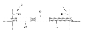
図2に示すように、第1,第2PC梁1,2が隣接状に設置されると、第1PC梁1の複数のネジ節鉄筋10と、この複数のネジ節鉄筋10に対応する第2PC梁2の複数のネジ節鉄筋20が、夫々、同軸状に配置されて僅かな隙間を空けて対向し、これら複数のネジ節鉄筋10,20の対向端部同士が、複数の外嵌ナット部材30(機械式継手30)を介して接続される。
As shown in FIG. 2, when the first and
この場合、図3に示すように、各外嵌ナット部材30が、第1PC梁1のネジ節鉄筋10の端部に、第2PC梁2と干渉しないように外嵌螺合された状態で、第1,第2PC梁1,2が設置された後、外嵌ナット部材30を回動させる。すると、図4に示すように、外嵌ナット部材30が、第2PC梁2のネジ節鉄筋20の方へ規定位置まで移動しつつ、第2PC梁2のネジ節鉄筋20の端部にも外嵌螺合される。
In this case, as shown in FIG. 3, each external
ここで、第1,第2PC梁1,2の対となる2本のネジ節鉄筋10,20のネジ位相が合わない(ネジピッチの連続性を確保できない)場合、また、対となる2本のネジ節鉄筋10,20の軸心がずれた場合、図3に示すように、第1PC梁1のネジ節鉄筋10の端部に外嵌螺合された外嵌ナット部材30を回動させて、図4に示すように、第2PC梁2のネジ節鉄筋20の方へ規定位置まで移動させつつ、第2PC梁2のネジ節鉄筋20の端部に外嵌螺合させることが困難になる。
Here, when the screw phases of the two
本発明のプレキャスト梁の製造方法及びプレキャスト梁の製造用治具50は、上記課題を改善できるものであり、以下、このプレキャスト梁の製造方法とプレキャスト梁の製造用治具50について詳しく説明する。
The precast beam manufacturing method and the precast
先ず、PC梁40の製造用治具50について説明する。
このPC梁40の製造用治具50は、隣接状に設置される1対のPC梁40(第1,第2PC梁1,2)の同軸状の対となる2本のネジ節鉄筋41(10,20)の対向端部同士を外嵌ナット部材30(機械式継手30)を介して接続可能なプレキャスト梁40を、複数のネジ節鉄筋41を型枠45に対して所定位置にセットした後に型枠45内にコンクリート42を打設して製造する際に用いるものである。
First, the
The
図5〜図15に示すように、製造用治具50は、カプラー51、カプラー保持部材52、調芯締結機構53、ダブルナット54、アングル部材55、バー部材56を備え、カプラー51と調芯締結機構53とダブルナット54は、PC梁40のネジ節鉄筋41の数(8本)に相当する複数組(8組)設けられ、カプラー保持部材52とアングル部材55とバー部材56は、上筋となる複数(4本)のネジ節鉄筋41と下筋となる複数(4本)のネジ節鉄筋41とに対応して2組設けられている。
As shown in FIGS. 5 to 15, the
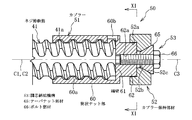
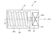
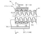
図10〜図13に示すように、カプラー51は、ネジ節鉄筋41の一端部に外嵌螺合される筒状ナット部60と、筒状ナット部60の一端を塞ぐように設けられてネジ節鉄筋41の一端部が当接して押圧可能な鉛直平滑面を有する端壁61とを有し、この筒状ナット部60と端壁61が一体形成され、キャップ状に構成されている。筒状ナット部60は、ネジ節鉄筋41のネジピッチの4〜5倍程度の長さを有し、ネジ節鉄筋41のネジ部分が比較的粗く成形されることから、この筒状ナット部60はネジ節鉄筋41に適度に遊嵌状に螺合されるように形成されている。
As shown in FIGS. 10 to 13, the
カプラー51が締め付け側へ回動されることで、カプラー51の端壁61にネジ節鉄筋41の一端が当接した状態で、カプラー51とネジ節鉄筋41の両ネジ山60a,41aのテーパが互いに押圧され、そのテーパ機能によりカプラー51の軸心C1に対してネジ節鉄筋41の一端部の軸心C2が調芯される。
By rotating the
また、カプラー51には、端壁61から筒状ナット部60と反対側へ突出する係合部62が一体形成され、この係合部62及び端壁61には、カプラー51の軸心C1を中心とするネジ孔62aが貫通状に形成されている。係合部62は、外周面に1対の水平平滑面を有する断面小判形に形成され、係合部62の端面は鉛直平滑面に形成されている。尚、筒状ナット部60には、ネジ節鉄筋41の一端が端壁61に当接したことを確認できる確認孔60bが形成されている。
Further, the
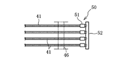
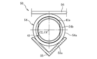
図7、図8、図10、図11に示すように、カプラー保持部材52は、複数(4つ)のカプラー51を係合保持するものであり、型枠45に取り外し可能に固定される。カプラー保持部材52は、長細く形成されネジ節鉄筋41の軸心C2と直交する水平方向に延びる姿勢でセットされ、カプラー保持部材52には、その長さ方向へ延び且つ複数のカプラー51の係合部60が回転不能に係合する凹溝52aが形成されている。
As shown in FIGS. 7, 8, 10, and 11, the
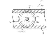
図10に示すように、調芯締結機構53は、カプラー保持部材52に対してカプラー51の軸心C1を調芯した状態でカプラー51をカプラー保持部材52に締結するものである。カプラー保持部材52には、凹溝52aからその反対側へ貫通する複数(4つ)の貫通孔52bであって、複数(4本)のネジ節鉄筋41に夫々対応する複数(4つ)の貫通孔52が形成され、その貫通孔52bのうち凹溝52aと反対側部分がテーパ穴部52cに形成されている。
As shown in FIG. 10, the
調芯締結機構53は、テーパナット部材65、ボルト部材66を有し、テーパナット部材65がカプラー保持部材52のテーパ穴部52cに係合され、ボルト部材66が、テーパナット部材65を摺動自在に挿通するとともに、カプラー保持部材52の貫通孔52bを貫通して、カプラー51のネジ孔62aに螺合される。
The
ボルト部材66が締め付け側へ回動されることで、カプラー保持部材52の凹溝52aの奥端面にカプラー51の端面が当接した状態で、カプラー保持部材52のテーパ穴部52cとテーパナット部材65が互いに押圧され、そのテーパ機能によりカプラー保持部材52の貫通孔52bの軸心C3に対してカプラー51の軸心C1が調芯される。
When the
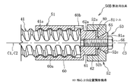
以上のことから、製造用治具50は、カプラー51の軸心C1に対してネジ節鉄筋41の一端部の軸心C2を調芯した状態で、且つ、カプラー保持部材52に対してカプラー51の軸心C1を調芯した状態で、カプラー51とカプラー保持部材52と調芯締結機構53を介して、ネジ節鉄筋41の一端部を型枠45に位置決め保持するとともにネジ節鉄筋41のネジ山41aの一端の軸心回りの位置を設定可能に構成されている。
From the above, the
実施例1の場合、複数のカプラー51がカプラー保持部材52に係合保持された状態で、その複数のカプラー51のネジ山60aの両端の軸心回りの位置は夫々全て同位置となるように構成され、故に、この複数のカプラー51を装着した複数のネジ節鉄筋41のネジ山41aの一端の軸心回りの位置は全て同位置に設定される。
In the case of the first embodiment, in the state where the plurality of
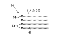
図14、図15に示すように、ダブルナット54は、ネジ節鉄筋41の他端部に互いに締結可能に外嵌螺合される円筒外周面54aを有するものである。ダブルナット54は同構造の1対のナット部材からなり、夫々、ネジ節鉄筋41のネジピッチの2倍程度の長さを有し、ネジ節鉄筋41のネジ部分が比較的粗く成形されることから、ダブルナット54はネジ節鉄筋41に適度に遊嵌状に螺合されるように形成されている。
As shown in FIGS. 14 and 15, the
ダブルナット54の一方が他方に対して締め付け側へ回動されることで、ダブルナット54が互いに締結され、これにより、ダブルナット54とネジ節鉄筋41の両ネジ山54b,41aのテーパが互いに押圧され、そのテーパ機能によりダブルナット54の軸心C4に対してネジ節鉄筋41の他端部の軸心C2が調芯される。
When one of the
図8、図14、図15に示すように、アングル部材55は、型枠45に固定されて複数(4つ)のダブルナット54を載置するものである。アングル部材55は、長細く形成されネジ節鉄筋41の軸心C2と直交する水平方向に延びる姿勢で型枠45に固定される。
As shown in FIGS. 8, 14, and 15, the
アングル部材55には、複数(4本)のネジ節鉄筋41に夫々対応する複数(4つ)の断面V形の鉄筋受け部55aが一体的に設けられ、各鉄筋受け部55aに、ダブルナット54がその円筒外周面54aを当接させた状態で載置される。各鉄筋受け部55aは、ネジ節鉄筋41(ダブルナット54)が軸心方向へ多少移動しても、ダブルナット54を載置可能に構成されている。
The
図8、図14、図15に示すように、バー部材56は、複数(4つ)のダブルナット54をアングル部材55に押えるものである。このバー部材56は、複数のダブルナット54をアングル部材55に押えた状態で、その両端部分がアングル部材55(又は型枠45)に複数のボルト等により締結される。
As shown in FIGS. 8, 14, and 15, the
次に、PC梁40の製造方法について説明する。
このPC梁40の製造方法は、隣接状に設置される1対のPC梁40(第1,第2PC梁1,2)の同軸状の対となる2本のネジ節鉄筋41(10,20)の対向端部同士を外嵌ナット部材30(機械式継手30)を介して接続可能なプレキャスト梁40を、8本のネジ節鉄筋41を型枠45に対して所定位置にセットした後に型枠45内にコンクリート42を打設して製造するものであり、ここで、前記製造用治具50が用いられる。
Next, a method for manufacturing the
The method of manufacturing the
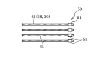
このPC梁40の製造方法では、準備工程において、図8に示すように、8本のネジ節鉄筋41を型枠45に対してセットする際、先ず、図5に示すように、各ネジ節鉄筋41の一端部に筒状ナット部60と筒状ナット部60の一端を塞ぐ端壁61とを有するキャップ状のカプラー51を外嵌螺合させ、このカプラー51の端壁61にネジ節鉄筋41の一端が当接して押圧可能にカプラー51を装着するとともに、図6に示すように、各ネジ節鉄筋41の他端部に円筒外周面54aを有するダブルナット54を互いに締結可能に外嵌螺合させて装着する。
In the method of manufacturing the
次に、位置決め工程において、各ネジ節鉄筋41に対して、カプラー51を締め付け側へ回動させることで、カプラー51の端壁61にネジ節鉄筋41の一端が当接した状態で、カプラー51とネジ節鉄筋41の両ネジ山60a,41aのテーパが互いに押圧され、そのテーパ機能によりカプラー51の軸心C1に対してネジ節鉄筋41の一端部の軸心C2を調芯し、また、ダブルナット54の一方を他方に対して締め付け側へ回動させることで、ダブルナット54が互いに締結され、これにより、ダブルナット54とネジ節鉄筋41の両ネジ山54b,41aのテーパが互いに押圧され、そのテーパ機能によりダブルナット54の軸心C4に対してネジ節鉄筋41の一端部の軸心C2を調芯する。
Next, in the positioning step, the
続いて、位置決め工程において、仮組みのため、図7に示すように、8本のネジ節鉄筋41を架台46に所定配列で配置し、上筋となる4本のネジ節鉄筋41の一端部に装着された4個のカプラー51を上筋用のカプラー保持部材52に係合保持させるとともに、下筋となる4本のネジ節鉄筋41の一端部に装着された4個のカプラー51を下筋用のカプラー保持部材52に係合保持させる。その際、8個のカプラー51のネジ山60aの両端の軸心回りの位置が夫々全て同位置となるように、図10、図11に示すように、各カプラー51の係合部62をカプラー保持部材52の凹溝52aに係合させる。
Subsequently, in the positioning step, for temporary assembly, as shown in FIG. 7, eight screw joint reinforcing
そして、調芯締結機構53のテーパナット部材65とボルト部材66により、カプラー保持部材52に各カプラー51を締結するとともに、カプラー保持部材52に対して各カプラー51の軸心C1を調芯して、また、複数の補助筋(図示略)も架台46に対して所定配列で設置して、仮組みが完了する。
Then, each of the
続いて、位置決め工程において、図8に示すように、仮組みされた8本のネジ節鉄筋41、8個のカプラー51、2つのカプラー保持部材52、8個のダブルナット54を含む仮組み構造体を一体的に型枠45に対してセットする。ここで、型枠45には、鉄筋止め枠45a,45bが立設されており、鉄筋止め枠45bには、上筋用と下筋用の両アングル部材55が所定位置に予め固定されている。
Subsequently, in the positioning step, as shown in FIG. 8, a temporary assembly structure including eight temporarily assembled screw joints 41, eight
この場合、鉄筋止め枠45aに、上筋用と下筋用のカプラー保持部材52を所定位置に複数のボルト等で締結固定するとともに、図14、図15に示すように、上筋用の4個のダブルナット54を上筋用のアングル部材55(鉄筋受け部55a)に載置し、その4個のダブルナット54を上筋用のバー部材56でアングル部材55に押えて、そのバー部材56を鉄筋止め枠45bに複数のボルト等で締結固定し、また、下筋用の4個のダブルナット54を下筋用のアングル部材55(鉄筋受け部55a)に載置し、その4個のダブルナット54を下筋用のバー部材56でアングル部材55に押えて、そのバー部材56を鉄筋止め枠45bに複数のボルト等で締結固定する。
In this case, a
こうして、型枠45に対して8本のネジ節鉄筋41の軸心を夫々所期の軸心位置に合わせ、各ネジ節鉄筋41の一端部を型枠45に位置決め保持するとともにネジ節鉄筋41のネジ山41aの一端の軸心回りの位置を設定するようにして、8本のネジ節鉄筋41を型枠45に対して所定位置にセットすることができ、この状態で、型枠45にコンクリート42を打設して、その後、各ネジ節鉄筋41に装着したカプラー51とダブルナット54を取り外して、図9に示すPC梁40を製造する。
In this way, the axial centers of the eight
ここで、実施例1の場合、前記のように、8個のカプラー51のネジ山60aの両端の軸心回りの位置が夫々全て同位置であるため、図2に示すように、上記製造方法で製造された第1,第2PC梁1,2の対となる2本のネジ節鉄筋10,20の一端同士間の距離Lがネジ節鉄筋10,11のネジピッチの正数倍になると、対となる2本のネジ節鉄筋10,20のネジ位相が合う(ネジピッチの連続性を確保できる)ことになり、そうなるように、型枠46に対するカプラー51の保持位置(ネジ節鉄筋41の一端の位置)等に基づくネジ位相で、カプラー51のネジ部分が形成されている。
Here, in the case of Example 1, as described above, since the positions around the axial centers of both ends of the
以上説明したPC梁40の製造技術によれば次の効果を奏する。
準備工程において、複数のネジ節鉄筋41を型枠45に対してセットする際、先ず、各ネジ節鉄筋41の一端部にカプラー51を外嵌螺合させ、このカプラー51の端壁61にネジ節鉄筋41の一端が当接して押圧可能にカプラー51を装着し、位置決め工程において、カプラー51の軸心C1に対してネジ節鉄筋41の一端部の軸心C2を調芯した状態で、カプラー51を介してネジ節鉄筋41の一端部を型枠45に位置決め保持するとともにネジ節鉄筋41のネジ山41aの一端の軸心回りの位置を設定する。
According to the manufacturing technique of the
In the preparation step, when setting the plurality of screw joint reinforcing
また、準備工程において、各ネジ節鉄筋41の他端部にダブルナット54を互いに締結可能に外嵌螺合させて装着し、位置決め工程において、ダブルナット54の軸心C4に対してネジ節鉄筋41の他端部の軸心C2を調芯した状態で、ネジ節鉄筋41の他端部を型枠45に位置決め保持する。
Further, in the preparation step, the
つまり、PC梁40を製造する際、型枠45に対して各ネジ節鉄筋41の軸心C2を所期の軸心位置に合わせて、型枠45に対してネジ節鉄筋41のネジ山41aの一端の軸心方向の位置及び軸心回りの位置を設定することができる。従って、1対のPC梁40が建設現場で隣接状に設置された場合、対となる2本のネジ節鉄筋41の軸心を一致させることができ、そのPC梁40の設置位置に応じて、前記設定により、対となる2本のネジ節鉄筋41のネジ位相を合わせることができる。その結果、対となる2本のネジ節鉄筋41の対向端部同士を外嵌ナット部材30を介して円滑に確実に接続できる。
That is, when the
位置決め工程において、複数のネジ節鉄筋41の一端部に装着された複数のカプラー51を、型枠45に固定されるカプラー保持部材52に係合保持するので、複数のネジ節鉄筋41の一端部を複数のカプラー51とそれらに共通のカプラー保持部材52を介して型枠45に位置決め保持することができ、複数のネジ節鉄筋41の一端部を型枠45に位置決め保持する作業負荷を軽減できる。
In the positioning step, the plurality of
位置決め工程において、調芯締結機構53のテーパナット部材65とボルト部材66により、カプラー保持部材52に対してカプラー51の軸心C1を調芯するので、カプラー51をカプラー保持部材52に締結するとともに、カプラー保持部材52に対してカプラー51の軸心C1を簡単確実に調芯することができ、ネジ節鉄筋41の軸心C2を所期位置に正確に合わせて、対となる2本のネジ節鉄筋41の軸心C2を確実に一致させることができる。
In the positioning step, the shaft center C1 of the
位置決め工程において、複数のダブルナット54を型枠45に固定されたアングル部材55に載置し、複数のダブルナット54をバー部材56でアングル部材55に押えるので、複数のダブルナット54をアングル部材55とバー部材56を介して型枠45に確実に保持することができる。
In the positioning step, the plurality of
図16に示すように、実施例2のPC梁40の製造用治具50Aは、実施例1のカプラー51を変更し、カプラー保持部材52に対してネジ節鉄筋41のネジ山41aの一端の軸心回りの位置を調節する軸心回り位置調節機構70を備えたものである。尚、実施例1と基本的に同じものには同一符号を付して説明を省略する。
As illustrated in FIG. 16, the
このカプラー51Aは、カプラー基部75と、このカプラー基部75にカプラー51Aの軸心C1回りに回転可能に連結されたカプラー本体部76とを有する。カプラー基部75に係合部75aが形成され、この係合部75aがカプラー保持部材52の凹溝52aに回転不能に係合される。カプラー基部75に、カプラー51Aの軸心C1を中心とするネジ孔75bが貫通状に形成され、このネジ孔75bに調芯締結機構53のボルト部材66が内嵌螺合される。
The
カプラー本体部76に、実施例1の筒状ナット部60と端壁61と同機能の筒状ナット部77と端壁78が一体形成されている。カプラー基部75にカプラー本体部76を回転可能に連結するために、カプラー基部75の係合部52aと反対側の端部に円形凹部75cが形成され、カプラー本体部76に、端壁78から筒状ナット部77と反対側へ突出して円形凹部75cに摺動自在に係合するキャップ状係合部76aが一体形成されている。
A
キャップ状係合部76aの端壁に、ネジ孔75bに略連続するボルト孔76bが形成されている。ボルト71の頭部がキャップ状係合部76aの収容凹部76cに収容され、端壁77よりも筒状ナット部77側へ突出しないようにした状態で、そのボルト71がボルト孔76bを挿通してネジ孔75bに内嵌螺合されている。
Bolt holes 76b that are substantially continuous to the screw holes 75b are formed in the end wall of the cap-shaped
軸心回り位置調節機構70は、ネジ孔75b、円形凹部75c、キャップ状係合部76a、ボルト71等で構成され、ボルト71を弛めた状態で、カプラー本体部76を回動させ、所望の位置でボルト71を締めて、カプラー本体部76を固定することができる。即ち、カプラー保持部材52に対して、カプラー本体部76の軸心回りの位置を調節することにより、ネジ節鉄筋41のネジ山41aの一端の軸心回りの位置を調節する。
The shaft center
この製造用治具50Aを用いたPC梁40の製造方法では、軸心回り位置調節機構70により、対となる2本のネジ節鉄筋41のネジ位相が合うように、ネジ節鉄筋41のネジ山41aの一端の軸心回りの位置を調節することができる。例えば、実施例1のように、8個のカプラー51のネジ山60aの両端の軸心回りの位置が夫々全て同位置であるように、カプラー51のネジ部分を形成しようとしても、成形誤差によりそうならない場合に、ネジ節鉄筋41のネジ山41aの一端の軸心回りの位置を調節して対応し、対となる2本のネジ節鉄筋40の一端同士間の距離Lがネジ節鉄筋40のネジピッチの正数倍になるようにすることができる。
In the method of manufacturing the
図17に示すように、実施例3のPC梁40の製造用治具50Bは、カプラー保持部材52に対してネジ節鉄筋41のネジ山41aの一端の軸心方向の位置を調節する軸心方向位置調節機構80を備えたものである。尚、実施例1と基本的に同じものには同一符号を付して説明を省略する。
As illustrated in FIG. 17, the
軸心方向位置調節機構80と、カプラー51とカプラー保持部材52との間に介装されるシム81を備えている。シム81は、カプラー保持部材52の凹部52に収容可能に形成され、その中央部分にボルト部材66が挿通する孔81aが形成されている。ここで、シム81として厚さが異なる複数のシム81を用意しておくことが好ましい。即ち、カプラー保持部材52に対して、カプラー51の軸心方向の位置を調節することにより、ネジ節鉄筋41のネジ山41aの一端の軸心方向の位置を調節する。
An axial center
この製造用治具50Bを用いたPC梁40の製造方法では、軸心方向位置調節機構80により、対となる2本のネジ節鉄筋41のネジ位相が合うように、ネジ節鉄筋41のネジ山41aの一端の軸心方向の位置を調節することができる。
In the method of manufacturing the
その他、本発明の趣旨を逸脱しない範囲において、前記開示事項以外の種々の変更を付加して実施可能である。また、本発明については、隣接状に設置される1対のプレキャスト梁の同軸状の2本のネジ節鉄筋の対向端部同士を接続する場合に、上記外嵌ナット部材30に限らず、種々の外嵌ナット部材を有する機械式継手を介して接続可能なプレキャスト梁を製造する際に適用することができる。
In addition, various modifications other than the disclosed items can be added and implemented without departing from the spirit of the present invention. In addition, the present invention is not limited to the above-described external
1,2,40 プレキャスト梁(PC梁)
10,20,41 ネジ節鉄筋
11,21,42 コンクリート
30 外嵌ナット部材(機械式継手)
45 型枠
50,50A,50B 製造用治具
51,51A カプラー
52 カプラー保持部材
53 調芯締結機構
54 ダブルナット
54a 円筒外周面
55 アングル部材
56 バー部材
60,77 筒状ナット部
61,78 端壁
65 テーパナット部材
66 ボルト部材
80 軸心方向位置調節機構
81 シム
1,2,40 Precast beam (PC beam)
10, 20, 41 Threaded
45
Claims (10)
前記複数のネジ節鉄筋を型枠に対してセットする際、先ず、各ネジ節鉄筋の一端部に筒状ナット部と筒状ナット部の一端を塞ぐ端壁とを有するキャップ状のカプラーを外嵌螺合させ、このカプラーの端壁にネジ節鉄筋の一端が当接して押圧可能にカプラーを装着する準備工程と、
前記カプラーの軸心に対してネジ節鉄筋の一端部の軸心を調芯した状態で、前記カプラーを介してネジ節鉄筋の一端部を型枠に位置決め保持するとともにネジ節鉄筋のネジ山の一端の軸心回りの位置を設定する位置決め工程と、
を備えたことを特徴とするプレキャスト梁の製造方法。 A plurality of screw nodes can be connected to a precast beam that can connect two opposite end portions of two coaxial screw joints of a pair of precast beams installed adjacent to each other via a mechanical joint having an external fitting nut member. In the method of manufacturing a precast beam in which concrete is placed in a mold after the rebar is set at a predetermined position with respect to the mold,
When setting the plurality of screw rebars on the formwork, first, a cap-shaped coupler having a cylindrical nut portion and an end wall that closes one end of the cylindrical nut portion is removed at one end portion of each screw rebar. A preparatory step of fitting and screwing, and attaching the coupler so that one end of the threaded bar contacts the end wall of the coupler and can be pressed;
In a state where the axis of one end of the screw rebar is aligned with the axis of the coupler, the one end of the screw rebar is positioned and held on the mold via the coupler, and the thread of the screw rebar is A positioning step for setting a position around the axis of one end;
A method for producing a precast beam, comprising:
前記位置決め工程において、ダブルナットの軸心に対してネジ節鉄筋の他端部の軸心を調芯した状態で、ネジ節鉄筋の他端部を型枠に位置決め保持することを特徴とする請求項1〜4の何れかに記載のプレキャスト梁の製造方法。 In the preparatory step, a double nut having a cylindrical outer peripheral surface is fitted to the other end of each threaded reinforcing bar by being externally screwed so that they can be fastened together,
In the positioning step, the other end portion of the screw joint reinforcing bar is positioned and held on the formwork in a state where the axis of the other end portion of the screw joint reinforcing rod is aligned with the axis of the double nut. Item 5. A method for producing a precast beam according to any one of Items 1 to 4.
前記ネジ節鉄筋の一端部に外嵌螺合される筒状ナット部と筒状ナット部の一端を塞ぐように設けられてネジ節鉄筋の一端部が当接して押圧可能な端壁とを有するキャップ状のカプラーと、
前記型枠に固定されカプラーを係合保持するカプラー保持部材とを備え、
前記カプラーの軸心に対してネジ節鉄筋の一端部の軸心を調芯した状態で、前記カプラーとカプラー保持部材を介してネジ節鉄筋の一端部を型枠に位置決め保持するとともにネジ節鉄筋のネジ山の一端の軸心回りの位置を設定可能に構成したことを特徴とするプレキャスト梁の製造用治具。 A plurality of screw nodes can be connected to a precast beam that can connect two opposite end portions of two coaxial screw joints of a pair of precast beams installed adjacent to each other via a mechanical joint having an external fitting nut member. A jig for producing a precast beam to be used when placing and manufacturing concrete in a mold after setting a reinforcing bar at a predetermined position with respect to the mold,
A cylindrical nut portion that is externally screwed to one end portion of the screw reinforcing bar, and an end wall that is provided so as to close one end of the cylindrical nut portion and that can be pressed against the one end portion of the screw reinforcing bar. A cap-shaped coupler,
A coupler holding member fixed to the mold and holding the coupler engaged,
In a state where the axis of one end of the screw rebar is aligned with the axis of the coupler, the one end of the screw rebar is positioned and held on the formwork via the coupler and the coupler holding member, and the screw rebar A jig for manufacturing a precast beam, characterized in that the position around the axis of one end of the thread can be set.
Priority Applications (1)
| Application Number | Priority Date | Filing Date | Title |
|---|---|---|---|
| JP2008322109A JP5442247B2 (en) | 2008-12-18 | 2008-12-18 | Precast beam manufacturing method and precast beam manufacturing jig |
Applications Claiming Priority (1)
| Application Number | Priority Date | Filing Date | Title |
|---|---|---|---|
| JP2008322109A JP5442247B2 (en) | 2008-12-18 | 2008-12-18 | Precast beam manufacturing method and precast beam manufacturing jig |
Publications (2)
| Publication Number | Publication Date |
|---|---|
| JP2010143047A true JP2010143047A (en) | 2010-07-01 |
| JP5442247B2 JP5442247B2 (en) | 2014-03-12 |
Family
ID=42563981
Family Applications (1)
| Application Number | Title | Priority Date | Filing Date |
|---|---|---|---|
| JP2008322109A Active JP5442247B2 (en) | 2008-12-18 | 2008-12-18 | Precast beam manufacturing method and precast beam manufacturing jig |
Country Status (1)
| Country | Link |
|---|---|
| JP (1) | JP5442247B2 (en) |
Citations (2)
| Publication number | Priority date | Publication date | Assignee | Title |
|---|---|---|---|---|
| JPS6153448U (en) * | 1984-09-13 | 1986-04-10 | ||
| JPH02178457A (en) * | 1988-12-28 | 1990-07-11 | Tokyo Tekko Kk | Precast concrete, manufacture thereof and formwork for precast concrete |
-
2008
- 2008-12-18 JP JP2008322109A patent/JP5442247B2/en active Active
Patent Citations (2)
| Publication number | Priority date | Publication date | Assignee | Title |
|---|---|---|---|---|
| JPS6153448U (en) * | 1984-09-13 | 1986-04-10 | ||
| JPH02178457A (en) * | 1988-12-28 | 1990-07-11 | Tokyo Tekko Kk | Precast concrete, manufacture thereof and formwork for precast concrete |
Also Published As
| Publication number | Publication date |
|---|---|
| JP5442247B2 (en) | 2014-03-12 |
Similar Documents
| Publication | Publication Date | Title |
|---|---|---|
| JP6750158B2 (en) | Adjustable mini jack coupler and usage | |
| US20170081853A1 (en) | Rebar connector having a pair of locking pieces and connection method for prefabricated rebar net using same | |
| CN110653934A (en) | Steel bar positioning device and method for prefabricated RC component | |
| KR20220023669A (en) | Reinforced connection system for precast concrete column and girder | |
| JP5442247B2 (en) | Precast beam manufacturing method and precast beam manufacturing jig | |
| JP5796940B2 (en) | Method for joining concrete members | |
| CN212742226U (en) | Steel bar positioning device | |
| JP2008190175A (en) | Joining method and joint structure of precast reinforced concrete beam members | |
| KR100919784B1 (en) | Beam-column connection of precast members and constructing method for the same | |
| KR101360360B1 (en) | Form assembly easily installed distance maintenance implement | |
| CN114508168B (en) | Green assembled concrete prefabricated part and preparation method thereof | |
| JP2004300888A (en) | Irregularity correcting tool for steel-frame column | |
| KR20200053874A (en) | Centrifugal casted rectangular PC column with hollow section and manufacturing method thereof | |
| CN112012402B (en) | A steel formwork concrete composite cross-shaped internode column | |
| JP5771467B2 (en) | Building unit positioning structure, building unit positioning method, and unit guide installation method | |
| CN210857496U (en) | Connecting structure between precast beam and precast column in assembled concrete frame | |
| JP6405070B1 (en) | Seismic reinforcement structure for concrete structure and seismic structure construction method for concrete structure | |
| JPH03244733A (en) | Exterior wall connection structure | |
| JP6921413B2 (en) | Reinforcing bar joints and rebar assemblies, as well as precast reinforced concrete bodies | |
| CN112727083A (en) | Formwork erecting method for reserved hole | |
| KR102719314B1 (en) | horizontal coupling method of precast concrete | |
| JP2026513420A (en) | Improved adjustable compact lifting coupler and instructions for use | |
| KR101320697B1 (en) | Concrete mold connector and method for connecting concrete mold using concrete mold connector | |
| KR200373289Y1 (en) | Separator for prefabricated panel | |
| JP2005194750A (en) | Correction jig |
Legal Events
| Date | Code | Title | Description |
|---|---|---|---|
| A621 | Written request for application examination |
Free format text: JAPANESE INTERMEDIATE CODE: A621 Effective date: 20111129 |
|
| A977 | Report on retrieval |
Free format text: JAPANESE INTERMEDIATE CODE: A971007 Effective date: 20121212 |
|
| A131 | Notification of reasons for refusal |
Free format text: JAPANESE INTERMEDIATE CODE: A131 Effective date: 20121217 |
|
| A521 | Request for written amendment filed |
Free format text: JAPANESE INTERMEDIATE CODE: A523 Effective date: 20130214 |
|
| TRDD | Decision of grant or rejection written | ||
| A01 | Written decision to grant a patent or to grant a registration (utility model) |
Free format text: JAPANESE INTERMEDIATE CODE: A01 Effective date: 20131119 |
|
| A61 | First payment of annual fees (during grant procedure) |
Free format text: JAPANESE INTERMEDIATE CODE: A61 Effective date: 20131218 |
|
| R150 | Certificate of patent or registration of utility model |
Free format text: JAPANESE INTERMEDIATE CODE: R150 Ref document number: 5442247 Country of ref document: JP Free format text: JAPANESE INTERMEDIATE CODE: R150 |
|
| R250 | Receipt of annual fees |
Free format text: JAPANESE INTERMEDIATE CODE: R250 |
|
| R250 | Receipt of annual fees |
Free format text: JAPANESE INTERMEDIATE CODE: R250 |
|
| R250 | Receipt of annual fees |
Free format text: JAPANESE INTERMEDIATE CODE: R250 |
|
| R250 | Receipt of annual fees |
Free format text: JAPANESE INTERMEDIATE CODE: R250 |
|
| R250 | Receipt of annual fees |
Free format text: JAPANESE INTERMEDIATE CODE: R250 |
|
| R250 | Receipt of annual fees |
Free format text: JAPANESE INTERMEDIATE CODE: R250 |
|
| R250 | Receipt of annual fees |
Free format text: JAPANESE INTERMEDIATE CODE: R250 |
|
| R250 | Receipt of annual fees |
Free format text: JAPANESE INTERMEDIATE CODE: R250 |