JP2010142765A - Degassing device of vacuum treatment apparatus, degassing method of vacuum treatment apparatus, and vacuum treatment apparatus - Google Patents
Degassing device of vacuum treatment apparatus, degassing method of vacuum treatment apparatus, and vacuum treatment apparatus Download PDFInfo
- Publication number
- JP2010142765A JP2010142765A JP2008324951A JP2008324951A JP2010142765A JP 2010142765 A JP2010142765 A JP 2010142765A JP 2008324951 A JP2008324951 A JP 2008324951A JP 2008324951 A JP2008324951 A JP 2008324951A JP 2010142765 A JP2010142765 A JP 2010142765A
- Authority
- JP
- Japan
- Prior art keywords
- vacuum
- gas
- degassing
- processing apparatus
- pipe
- Prior art date
- Legal status (The legal status is an assumption and is not a legal conclusion. Google has not performed a legal analysis and makes no representation as to the accuracy of the status listed.)
- Pending
Links
- 238000007872 degassing Methods 0.000 title claims abstract description 50
- 238000009489 vacuum treatment Methods 0.000 title 3
- 239000007789 gas Substances 0.000 claims abstract description 143
- 239000012159 carrier gas Substances 0.000 claims abstract description 49
- 238000001816 cooling Methods 0.000 claims abstract description 38
- 238000010438 heat treatment Methods 0.000 claims abstract description 25
- 238000011144 upstream manufacturing Methods 0.000 claims abstract description 16
- 238000000034 method Methods 0.000 claims description 34
- 239000011261 inert gas Substances 0.000 claims description 11
- 238000001179 sorption measurement Methods 0.000 claims 1
- 239000000498 cooling water Substances 0.000 description 3
- 230000015572 biosynthetic process Effects 0.000 description 2
- 230000001771 impaired effect Effects 0.000 description 2
- 238000001514 detection method Methods 0.000 description 1
- 238000010586 diagram Methods 0.000 description 1
- 239000007769 metal material Substances 0.000 description 1
- 238000012986 modification Methods 0.000 description 1
- 230000004048 modification Effects 0.000 description 1
- 239000003507 refrigerant Substances 0.000 description 1
- 238000011069 regeneration method Methods 0.000 description 1
Images
Landscapes
- Chemical Vapour Deposition (AREA)
Abstract
【課題】適正に脱ガス処理を行うことができる真空処理装置の脱ガス装置、真空処理装置の脱ガス方法および真空処理装置を提供することである。
【解決手段】ワークWを処理する真空チャンバ2が真空配管32を介して真空吸引装置31に接続された真空処理装置1に組み込まれ、真空吸引装置31と協働して、真空処理装置1の装置内部に吸着した吸着ガスを除去する真空処理装置1の脱ガス装置であって、吸着ガスを除去するためのキャリアガスのキャリアガス源16に連通し、キャリアガスを加熱して真空チャンバ2に供給する加熱ガス供給装置12と、真空吸引装置31の上流側近傍の真空配管32に介設され、真空吸引装置31に吸引されるキャリアガスを冷却するガス冷却装置33と、を備えたものである。
【選択図】図1A degassing apparatus for a vacuum processing apparatus, a degassing method for the vacuum processing apparatus, and a vacuum processing apparatus capable of appropriately performing degassing processing.
A vacuum chamber 2 for processing a workpiece W is incorporated in a vacuum processing apparatus 1 connected to a vacuum suction apparatus 31 via a vacuum pipe 32, and in cooperation with the vacuum suction apparatus 31, the vacuum processing apparatus 1 A degassing apparatus for the vacuum processing apparatus 1 that removes the adsorbed gas adsorbed inside the apparatus, communicated with a carrier gas source 16 of a carrier gas for removing the adsorbed gas, and heated into the vacuum chamber 2 by heating the carrier gas. A heating gas supply device 12 to be supplied and a gas cooling device 33 that is interposed in a vacuum pipe 32 in the vicinity of the upstream side of the vacuum suction device 31 and cools the carrier gas sucked into the vacuum suction device 31. is there.
[Selection] Figure 1
Description
本発明は、ワークを処理する真空処理装置に組み込まれ、真空処理装置の真空吸引手段と協働して装置内部に吸着した吸着ガスを除去する真空処理装置の脱ガス装置、真空処理装置の脱ガス方法および真空処理装置に関するものである。 The present invention is incorporated in a vacuum processing apparatus for processing a workpiece, and in cooperation with the vacuum suction means of the vacuum processing apparatus, removes the adsorbed gas adsorbed inside the apparatus, and removes the vacuum processing apparatus. The present invention relates to a gas method and a vacuum processing apparatus.
従来、このような真空装置(真空処理装置)として、加熱した不活性ガスにより、吸着ガスを除去するものが知られている(特許文献1参照)。
この真空装置は、ワークを処理する真空容器と、プロセスガスを供給するプロセスガス供給手段と、不活性ガスを供給する不活性ガス供給手段と、不活性ガスを加熱するガス加熱手段と、真空処理後のプロセスガス、不活性ガスおよび吸着ガスを排気するガス排気手段と、を有している。
この場合、プロセスガスを導入して真空処理を行い、プロセスガスを排気した後、不活性ガスを供給し、ガス加熱手段により不活性ガスを加熱することで、脱ガス処理を行い、ガス排気手段により脱ガス処理後の不活性ガスおよび吸着ガスを排気する。
The vacuum apparatus includes a vacuum vessel for processing a workpiece, a process gas supply unit for supplying a process gas, an inert gas supply unit for supplying an inert gas, a gas heating unit for heating the inert gas, and a vacuum process. Gas exhaust means for exhausting the subsequent process gas, inert gas and adsorbed gas.
In this case, after introducing the process gas, performing vacuum processing, exhausting the process gas, supplying the inert gas, and heating the inert gas by the gas heating means, the degassing treatment is performed, and the gas exhaust means Then, the inert gas and adsorbed gas after the degassing treatment are exhausted.
しかしながら、このような真空装置では、脱ガス後の高温の不活性ガスおよび吸着ガス(排ガス)をそのまま排気しているため、ガス排気手段に高温の排気ガスが流れ込む。すなわち、ガス排気手段は、排気ガスの熱によって加熱されることで負荷がかかり、その機能を十分発揮することができない。よって、排気ガスの排気処理が不十分となり、結果的に脱ガス処理がうまく行われないという問題があった。また、真空容器内にガス加熱手段を設ける必要があり、既存の装置に脱ガス機能を簡単に組み込むことができなかった。 However, in such a vacuum apparatus, since the high-temperature inert gas and the adsorbed gas (exhaust gas) after degassing are exhausted as they are, the high-temperature exhaust gas flows into the gas exhaust means. In other words, the gas exhaust means is loaded by being heated by the heat of the exhaust gas and cannot fully perform its function. Therefore, exhaust gas exhaust processing becomes insufficient, and as a result, there is a problem that degassing processing is not performed well. Moreover, it is necessary to provide a gas heating means in the vacuum vessel, and the degassing function cannot be easily incorporated into the existing apparatus.
本発明は、適正に脱ガス処理を行うことができる真空処理装置の脱ガス装置、真空処理装置の脱ガス方法および真空処理装置を提供することをその課題としている。 An object of the present invention is to provide a degassing apparatus for a vacuum processing apparatus, a degassing method for the vacuum processing apparatus, and a vacuum processing apparatus that can appropriately perform degassing processing.
本発明の真空処理装置の脱ガス装置は、ワークを処理する真空チャンバが真空配管を介して真空吸引手段に接続された真空処理装置に組み込まれ、真空吸引手段と協働して、真空処理装置の装置内部に吸着した吸着ガスを除去する真空処理装置の脱ガス装置であって、吸着ガスを除去するためのキャリアガスのガス源に連通し、キャリアガスを加熱して真空チャンバに供給する加熱ガス供給手段と、真空吸引手段の上流側近傍の真空配管に介設され、真空吸引手段に吸引されるキャリアガスを冷却するガス冷却手段と、を備えたことを特徴とする。 A degassing apparatus for a vacuum processing apparatus according to the present invention includes a vacuum processing apparatus in which a vacuum chamber for processing a work is incorporated in a vacuum processing apparatus connected to a vacuum suction means via a vacuum pipe. A degassing device for a vacuum processing device that removes the adsorbed gas adsorbed inside the device, and communicates with a carrier gas source for removing the adsorbed gas, and heats the carrier gas to be supplied to the vacuum chamber. A gas supply unit and a gas cooling unit that is interposed in a vacuum pipe near the upstream side of the vacuum suction unit and cools the carrier gas sucked by the vacuum suction unit are provided.
本発明の真空処理装置の脱ガス方法は、ワークを処理する真空チャンバが真空配管を介して真空吸引手段に接続された真空処理装置に組み込まれ、真空吸引手段と協働して、真空処理装置の装置内部に吸着した吸着ガスを除去する真空処理装置の脱ガス方法であって、真空チャンバに、吸着ガスを除去するためのキャリアガスを加熱して供給するガス加熱供給工程と、真空配管を介してキャリアガスを吸引すると共に、真空吸引手段の上流側近傍でキャリアガスを冷却するガス冷却吸引工程と、を備えたことを特徴とする。 The degassing method for a vacuum processing apparatus according to the present invention includes a vacuum processing apparatus in which a vacuum chamber for processing a work is incorporated in a vacuum processing apparatus connected to a vacuum suction means via a vacuum pipe. A degassing method for a vacuum processing apparatus for removing adsorbed gas adsorbed inside the apparatus, comprising: a gas heating supply step for heating and supplying a carrier gas for removing adsorbed gas to a vacuum chamber; and a vacuum pipe And a gas cooling and suction step of cooling the carrier gas in the vicinity of the upstream side of the vacuum suction means.
これらの構成によれば、加熱ガス供給手段により加熱したキャリアガスを真空チャンバに供給して脱ガスを行い、ガス冷却手段により脱ガス後のキャリアガスおよび吸着ガス(排気ガス)を冷却した後に、真空吸引手段により真空引きして排気するようになっている。すなわち、加熱された高温の排気ガスが、ガス冷却手段により冷却された後に、真空吸引手段に吸引されるため、真空吸引手段に熱的負荷がかかることがなく、その機能が損なわれることがない。よって、適正に脱ガス処理を行うことができる。また、脱ガス機能を簡単に附加することができる。 According to these configurations, the carrier gas heated by the heated gas supply means is supplied to the vacuum chamber to perform degassing, and after the carrier gas and the adsorbed gas (exhaust gas) after degassing are cooled by the gas cooling means, A vacuum suction means evacuates and exhausts. That is, since the heated high-temperature exhaust gas is cooled by the gas cooling means and then sucked by the vacuum suction means, the vacuum suction means is not subjected to a thermal load and its function is not impaired. . Therefore, the degassing process can be performed appropriately. In addition, a degassing function can be easily added.
この場合、加熱ガス供給手段は、真空チャンバに処理ガスを供給する処理ガス配管に接続され、当該処理ガス配管を介してキャリアガスを真空チャンバに供給することが、好ましい。 In this case, it is preferable that the heating gas supply means is connected to a processing gas pipe for supplying a processing gas to the vacuum chamber, and the carrier gas is supplied to the vacuum chamber via the processing gas pipe.
この構成によれば、加熱ガス供給手段が処理ガス配管に接続されているため、新たに真空チャンバにキャリアガス供給用の供給口を加工する必要がない。 According to this configuration, since the heating gas supply means is connected to the processing gas pipe, there is no need to newly process a supply port for supplying the carrier gas in the vacuum chamber.
この場合、真空配管は、介設したバイパス配管および迂回配管と、バイパス配管と迂回配管とを流路切り替えする流路切替え手段と、を有し、ガス冷却手段は、迂回配管に介設されていることが、好ましい。 In this case, the vacuum pipe has an intervening bypass pipe and a bypass pipe, and a flow path switching means for switching the flow path between the bypass pipe and the bypass pipe, and the gas cooling means is interposed in the bypass pipe. It is preferable.
この構成によれば、ガス冷却手段を排気ガスの排気処理時にのみ駆動させることができるため、真空処理後の処理ガスがガス冷却手段に触れることがない。また、真空配管を介してガス冷却手段を簡単に附加することができる。 According to this configuration, since the gas cooling means can be driven only during the exhaust gas exhaust process, the processing gas after the vacuum processing does not touch the gas cooling means. Moreover, a gas cooling means can be easily added via vacuum piping.
この場合、真空吸引手段は、低真空用のロータリーポンプと、高真空用のクライオポンプと、を有していることが、好ましい。 In this case, the vacuum suction means preferably has a rotary pump for low vacuum and a cryopump for high vacuum.
この構成によれば、ロータリーポンプにより大気圧から低真空に真空引きし、続いてクライオポンプで低真空から高真空に真空引きすることで、脱ガス後の排ガスを適切に排気することができる。すなわち、真空吸引手段を利用して、脱ガス後の排ガスを吸引処理することができる。なお、定期的に行うクライオポンプのクライオ再生の直前に、脱ガス処理を行うことが好ましい。 According to this configuration, the exhaust gas after degassing can be appropriately exhausted by evacuating from atmospheric pressure to low vacuum with a rotary pump and subsequently evacuating from low vacuum to high vacuum with a cryopump. That is, the exhaust gas after degassing can be sucked using a vacuum suction means. In addition, it is preferable to perform a degassing process immediately before cryo-regeneration of the cryopump periodically performed.
この場合、キャリアガスが、不活性ガスであることが、好ましい。 In this case, the carrier gas is preferably an inert gas.
この構成によれば、高温のキャリアガスにより真空チャンバ内が高温に達しても、生成物が生じることがないため、適正に脱ガス処理を行うことができる。 According to this configuration, even if the inside of the vacuum chamber reaches a high temperature due to the high-temperature carrier gas, no product is generated, so that the degassing process can be performed appropriately.
本発明の真空処理装置は、上記した真空処理装置の脱ガス装置、を備えたことが、好ましい。 The vacuum processing apparatus of the present invention preferably includes the above-described degassing apparatus for the vacuum processing apparatus.
この構成によれば、適正に脱ガス処理を行うことができる真空処理装置を提供することができる。 According to this structure, the vacuum processing apparatus which can perform a degassing process appropriately can be provided.
以下、添付した図面を参照して、脱ガス装置を搭載した真空処理装置について説明する。この真空処理装置は、ワークを収容した真空チャンバ内に供給したプロセスガス(処理ガス)をイオン化・ラジカル化して、ワーク表面に成膜処理等を行うものであると共に、キャリアガスを供給して真空チャンバの真空度に影響を及ぼす吸着ガスを脱ガスする機能を有するものである。 Hereinafter, a vacuum processing apparatus equipped with a degassing apparatus will be described with reference to the accompanying drawings. This vacuum processing apparatus ionizes and radicalizes a process gas (processing gas) supplied into a vacuum chamber containing a workpiece to form a film on the surface of the workpiece and supplies a carrier gas to form a vacuum. It has a function of degassing the adsorbed gas that affects the degree of vacuum of the chamber.
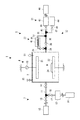
図1に示すように、真空処理装置1は、金属の素材で気密に構成され、ワークWを処理する真空チャンバ2と、真空チャンバ2にプロセスガスあるいはキャリアガスを供給するガス供給装置3と、真空チャンバ2内にプラズマを発生させ、プロセスガスをイオン化・ラジカル化するプラズマ発生装置4と、真空チャンバ2の真空化および脱ガスした吸着ガスを吸引排気するガス排気装置5と、から構成されている。 As shown in FIG. 1, a vacuum processing apparatus 1 is hermetically configured with a metal material, and a vacuum chamber 2 that processes a workpiece W, a gas supply apparatus 3 that supplies a process gas or a carrier gas to the vacuum chamber 2, A plasma generator 4 that generates plasma in the vacuum chamber 2 to ionize and radicalize the process gas, and a gas exhaust device 5 that sucks and exhausts the vacuumed and degassed adsorbed gas in the vacuum chamber 2. Yes.
ガス供給装置3は、プロセスガスを貯留しているプロセスガス源15および真空チャンバ2を連通する処理ガス配管11と、処理ガス配管11に接続された加熱ガス供給装置12と、処理ガス配管11に介設された処理ガスバルブ13および共通バルブ14を備えている。真空チャンバ2にプロセスガスを供給する場合には、処理ガスバルブ13および共通バルブ14を「開」とすることで、真空チャンバ2が所定のプロセスガス濃度になるようにプロセスガスを供給する。
The gas supply device 3 includes a
加熱ガス供給装置12は、上流側がキャリアガスを貯留しているキャリアガス源16に連通し、下流側がキャリアガス配管17を介して処理ガス配管11に接続されている。また、キャリアガス配管17には、キャリアガスバルブ18が介設されている。加熱ガス供給装置12は、キャリアガスが流れる内部流路に、例えばヒーターや赤外線ランプ等の加熱装置を臨ませて構成されている。真空チャンバ2にキャリアガスを供給する場合には、加熱ガス供給装置12を駆動すると共に、処理ガスバルブ13を「閉」とし、キャリアガスバルブ18および共通バルブ14を「開」とすることで、真空チャンバ2が所定のキャリアガス濃度になるようにキャリアガスを供給する。なお、処理ガスバルブ13およびキャリアガスバルブ18に換えて、処理ガス配管11およびキャリアガス配管17の接続部に設けたいわゆる三方弁で構成してもよい(図示省略)。
The heated
プラズマ発生装置4は、上部電極21と、下部電極22と、高周波電圧を印加する高周波電源23と、を有している。上部電極21は真空チャンバ2の上部に固定的に配設され、下部電極22は真空チャンバ2の下部に固定的に配設されている。下部電極22は、成膜処理の対象物であるワークWの載置板を兼ねており、固定治具24によってワークWを固定するようになっている。真空チャンバ2にプロセスガスが導入された状態で、プラズマ発生装置4を駆動することで、真空チャンバ2内にプラズマが発生し、プラズマによりイオン化・ラジカル化したプロセスガスがワークWに作用することで成膜処理を行う。そして、成膜処理終了後、プロセスガスを排気する。
The plasma generator 4 includes an
大気開放バルブ25は、いわゆる開閉バルブで構成されており、プロセスガスの排気後、大気を開放することで、真空チャンバ2内の圧力を大気圧に戻す。この状態で、ワークWの搬入搬出が行われると共に、必要に応じて後述する脱ガス処理が行われる。また、脱ガス処理後の真空チャンバ2内の圧力を大気圧に戻す際にも使用される。
The
ガス排気装置5は、真空チャンバ2を真空吸引する真空吸引装置31と、真空チャンバ2および真空吸引装置31を連通する真空配管32と、真空配管32に介設され、キャリアガスを冷却するガス冷却装置33と、から構成されている。
The gas exhaust device 5 is provided with a
真空配管32は、上流側が真空チャンバ2に接続されている上流側真空配管34と、下流側が真空吸引装置31に接続されている下流側真空配管35と、上流側真空配管34の下流端で分岐し下流側真空配管35の上流端で合流するバイパス配管36および迂回配管37と、から構成されている。バイパス配管36には、バイパス開閉バルブ38が介設され、迂回配管37には、迂回開閉バルブ39およびガス冷却装置33が介設されている。真空処理後のプロセスガスを排気する場合には、バイパス開閉バルブ38を「開」、迂回開閉バルブ39を「閉」とした状態で、真空吸引装置31により吸引排気する。なお、請求項にいう流路切替え手段は、バイパス開閉バルブ38および迂回開閉バルブ39から構成されている。また、流路切替え手段を、分岐部分に設けたいわゆる三方弁で構成してもよい。
The
ガス冷却装置33は、真空吸引装置31の上流側近傍に位置するように、迂回配管37における迂回開閉バルブ39の下流側に介設されている。また、ガス冷却装置33は、迂回配管37より細径に形成された複数本の冷却コイル41と、複数本の冷却コイル41を介して排気ガスを冷却する冷却水(冷媒)タンク42と、からなっている。そして、冷却水は、図外のチラーユニット等から冷却水タンク42に循環するようにして、供給される。脱ガス後のキャリアガスおよび吸着ガス(排気ガス)を排気する場合には、迂回開閉バルブ39を「開」、バイパス開閉バルブ38を「閉」とした状態で、ガス冷却装置33により排気ガスを冷却した後、真空吸引装置31により排気する。これにより、上流側真空配管34をキャリアガスが流れることにより、上流側真空配管34を脱ガスすることができるようになっている。
The
真空吸引装置31は、低真空用のロータリーポンプ43および高真空用のクライオポンプ44から構成されている。ロータリーポンプ43は、下流側真空配管35の下流側で分岐した一方のロータリー側分岐配管45に接続されており、排気管を介して排気処理設備46に連通している。一方、クライオポンプ44は、下流側真空配管35の下流側で分岐した他方のクライオ側分岐配管47の下流端に接続されている。また、両ポンプ43,44は、ロータリー側分岐配管45に介設した低真空用バルブ48、およびクライオ側分岐配管47に介設した高真空用バルブ49により、切替え可能に構成されている。
The
すなわち、真空チャンバ2の真空化を行う場合には、バイパス開閉バルブ38および低真空用バルブ48を「開」(迂回開閉バルブ39は「閉」)とした状態で、ロータリーポンプ43により吸引して低真空にする。続いて、低真空用バルブ48を「閉」とすると共に高真空用バルブ49を「開」として、クライオポンプ44により吸引して高真空にすることで行われる。一方、上述のように、脱ガス後の排気ガスの排気を行う場合には、迂回開閉バルブ39を「開」とし、且つガス冷却装置33を駆動しておいて、低真空用バルブ48を「開」として、ロータリーポンプ43によりガス冷却装置33によって冷却された排気ガスを吸引処理する。続いて、低真空用バルブ48を「閉」とすると共に高真空用バルブ49を「開」として、クライオポンプ44により吸引して高真空にすることで行われる。なお、いずれの場合においても、真空計51の検出結果に基づいて、ロータリーポンプ43およびクライオポンプ44が制御される。
That is, when the vacuum chamber 2 is evacuated, suction is performed by the
次に、真空処理装置1を用いた一連の処理動作について説明する。この処理操作は、上記したように、ワークW表面に成膜処理を施した後に行われ、真空チャンバ2に、吸着ガスを除去するためのキャリアガスを加熱して供給するガス加熱供給工程と、真空配管32を介してキャリアガスを吸引すると共に、真空吸引装置31の上流側近傍でキャリアガスを冷却するガス冷却吸引工程と、からなっている。なお、脱ガス処理は、定期的に行うクライオポンプ44のクライオ再生の直前に行うことが好ましい。
Next, a series of processing operations using the vacuum processing apparatus 1 will be described. As described above, this processing operation is performed after the film W is subjected to the film forming process, and the gas heating and supplying step of heating and supplying the carrier gas for removing the adsorbed gas to the vacuum chamber 2; It comprises a gas cooling and suction step of sucking the carrier gas through the
ガス加熱供給工程では、キャリアガス源16に貯留してあるキャリアガスを加熱ガス供給装置12により加熱して真空チャンバ2に供給する。これにより、加熱された高温のキャリアガスが真空チャンバ2全体に行き渡り、真空チャンバ2内に付着している吸着ガスと反応して、脱ガスが行われる。
In the gas heating and supplying step, the carrier gas stored in the
ガス冷却吸引工程では、排気ガスをガス冷却装置33により冷却した後、ロータリーポンプ43により吸引する。そして、ガス冷却装置33を駆動したままクライオポンプ44に切り替えて、さらに真空引きする。これにより、加熱された高温の排気ガスが、ガス冷却装置33により冷却された後に、ロータリーポンプ43およびクライオポンプ44に吸引処理される。なお、クライオポンプ44およびガス冷却装置33の使用状態になるまでに時間がかかる場合には、キャリアガスの供給直後に、排気ガスの排気が行えるように、これら装置を予め駆動させておくことが好ましい。
In the gas cooling suction process, the exhaust gas is cooled by the
以上の構成によれば、加熱ガス供給装置12により加熱したキャリアガスを真空チャンバ2に供給して脱ガスを行い、ガス冷却装置33により脱ガス後の排気ガスを冷却した後に、真空吸引装置31により排気するようになっている。すなわち、真空吸引装置31に熱的負荷がかかることがなく、その機能が損なわれることがない。よって、適正に脱ガス処理を行うことができる。また、脱ガス機能を簡単に附加することができる。
According to the above configuration, the carrier gas heated by the heated
なお、上記の実施形態では、加熱ガス供給装置12およびガス冷却装置33を組み込んだ真空処理装置1について説明したが、このような装置を搭載していない既存の真空処理装置1に、これら加熱ガス供給装置12およびガス冷却装置33を組み込むことも可能である。係る場合に、加熱ガス供給装置12は、既存の処理ガス配管11を改造してこれに接続され、ガス冷却装置33は、既存の真空配管32を改造してこれに接続されることになる。このように、簡単な改造により既存の真空処理装置1に、脱ガス装置である加熱ガス供給装置12およびガス冷却装置33を附加することができる。
In the above embodiment, the vacuum processing apparatus 1 incorporating the heating
1…真空処理装置 2…真空チャンバ 11…処理ガス配管 12…加熱ガス供給装置 31…真空吸引装置 32…真空配管 33…ガス冷却装置 34…上流側真空配管 35…下流側真空配管 36…バイパス配管 37…迂回配管 38…バイパス開閉バルブ 39…迂回開閉バルブ 43…ロータリーポンプ 44…クライオポンプ 48…低真空用バルブ 49…高真空用バルブ W…ワーク
DESCRIPTION OF SYMBOLS 1 ... Vacuum processing apparatus 2 ...
Claims (7)
前記真空吸引手段と協働して、前記真空処理装置の装置内部に吸着した吸着ガスを除去する真空処理装置の脱ガス装置であって、
前記吸着ガスを除去するためのキャリアガスのガス源に連通し、前記キャリアガスを加熱して前記真空チャンバに供給する加熱ガス供給手段と、
前記真空吸引手段の上流側近傍の前記真空配管に介設され、前記真空吸引手段に吸引される前記キャリアガスを冷却するガス冷却手段と、を備えたことを特徴とする真空処理装置の脱ガス装置。 A vacuum chamber for processing the workpiece is incorporated in a vacuum processing apparatus connected to a vacuum suction means via a vacuum pipe,
In cooperation with the vacuum suction means, a degassing device for a vacuum processing device for removing adsorbed gas adsorbed inside the vacuum processing device,
A heated gas supply means that communicates with a gas source of a carrier gas for removing the adsorbed gas, heats the carrier gas, and supplies the carrier gas to the vacuum chamber;
Degassing the vacuum processing apparatus, comprising: a gas cooling means that is interposed in the vacuum pipe near the upstream side of the vacuum suction means and cools the carrier gas sucked by the vacuum suction means apparatus.
前記バイパス配管と前記迂回配管とを流路切り替えする流路切替え手段と、を有し、
前記ガス冷却手段は、前記迂回配管に介設されていることを特徴とする請求項1または2に記載の真空処理装置の脱ガス装置。 The vacuum pipe includes an intervening bypass pipe and a bypass pipe,
Flow path switching means for switching the flow path between the bypass pipe and the bypass pipe,
The degassing apparatus for a vacuum processing apparatus according to claim 1 or 2, wherein the gas cooling means is interposed in the bypass pipe.
前記真空吸引手段と協働して、前記真空処理装置の装置内部に吸着した吸着ガスを除去する真空処理装置の脱ガス方法であって、
前記真空チャンバに、前記吸着ガスを除去するためのキャリアガスを加熱して供給するガス加熱供給工程と、
前記真空配管を介して前記キャリアガスを吸引すると共に、前記真空吸引手段の上流側近傍で前記キャリアガスを冷却するガス冷却吸引工程と、を備えたことを特徴とする真空処理装置の脱ガス方法。 A vacuum chamber for processing the workpiece is incorporated in a vacuum processing apparatus connected to a vacuum suction means via a vacuum pipe,
A degassing method for a vacuum processing apparatus that, in cooperation with the vacuum suction means, removes the adsorbed gas adsorbed inside the vacuum processing apparatus,
A gas heating and supplying step of heating and supplying a carrier gas for removing the adsorption gas to the vacuum chamber;
A degassing method for a vacuum processing apparatus, comprising: a gas cooling suction step for sucking the carrier gas through the vacuum pipe and cooling the carrier gas in the vicinity of the upstream side of the vacuum suction means. .
Priority Applications (1)
| Application Number | Priority Date | Filing Date | Title |
|---|---|---|---|
| JP2008324951A JP2010142765A (en) | 2008-12-22 | 2008-12-22 | Degassing device of vacuum treatment apparatus, degassing method of vacuum treatment apparatus, and vacuum treatment apparatus |
Applications Claiming Priority (1)
| Application Number | Priority Date | Filing Date | Title |
|---|---|---|---|
| JP2008324951A JP2010142765A (en) | 2008-12-22 | 2008-12-22 | Degassing device of vacuum treatment apparatus, degassing method of vacuum treatment apparatus, and vacuum treatment apparatus |
Publications (1)
| Publication Number | Publication Date |
|---|---|
| JP2010142765A true JP2010142765A (en) | 2010-07-01 |
Family
ID=42563751
Family Applications (1)
| Application Number | Title | Priority Date | Filing Date |
|---|---|---|---|
| JP2008324951A Pending JP2010142765A (en) | 2008-12-22 | 2008-12-22 | Degassing device of vacuum treatment apparatus, degassing method of vacuum treatment apparatus, and vacuum treatment apparatus |
Country Status (1)
| Country | Link |
|---|---|
| JP (1) | JP2010142765A (en) |
Cited By (1)
| Publication number | Priority date | Publication date | Assignee | Title |
|---|---|---|---|---|
| CN119465019A (en) * | 2025-01-13 | 2025-02-18 | 上海陛通半导体能源科技股份有限公司 | A device for rapidly cooling semiconductor components after high-temperature degassing |
-
2008
- 2008-12-22 JP JP2008324951A patent/JP2010142765A/en active Pending
Cited By (1)
| Publication number | Priority date | Publication date | Assignee | Title |
|---|---|---|---|---|
| CN119465019A (en) * | 2025-01-13 | 2025-02-18 | 上海陛通半导体能源科技股份有限公司 | A device for rapidly cooling semiconductor components after high-temperature degassing |
Similar Documents
| Publication | Publication Date | Title |
|---|---|---|
| JP2009534574A5 (en) | ||
| CN102741976B (en) | There is the dual cavity treatment system of shared vacuum pump | |
| JP4982320B2 (en) | Substrate processing equipment | |
| TWI534074B (en) | Ozone gas concentration method and device thereof | |
| JP5377666B2 (en) | Vacuum exhaust apparatus, vacuum exhaust method and substrate processing apparatus | |
| JP2013020954A5 (en) | Method and structure for quickly switching between different process gases in a plasma ion source | |
| JPH01268030A (en) | Plasma etching method and device | |
| TW200641981A (en) | Plasma processing apparatus | |
| CN103426746A (en) | Substrate processing apparatus and substrate processing method | |
| JP5669659B2 (en) | Cryopump and vacuum exhaust method | |
| JP2009026779A (en) | Vacuum processing equipment | |
| JP6044352B2 (en) | Organic material coating apparatus and organic material coating method using the same | |
| KR20110130481A (en) | Detaching Method of Object and Processing Device | |
| JP2010142765A (en) | Degassing device of vacuum treatment apparatus, degassing method of vacuum treatment apparatus, and vacuum treatment apparatus | |
| KR20140035832A (en) | Etching apparatus and etching method | |
| KR20180131400A (en) | Decompression drying apparatus | |
| JP2010144233A (en) | Degassing processing device of vacuum treatment apparatus, and vacuum treatment apparatus | |
| WO2017187787A1 (en) | Ozone gas concentration method and ozone gas concentration device | |
| JP2017197422A (en) | Ozone gas concentration method and ozone gas concentration apparatus | |
| JP5956754B2 (en) | Vacuum exhaust system | |
| JP2708569B2 (en) | Vacuum device degassing method and degassing device | |
| JP2008241533A (en) | Sample introduction apparatus and sample introduction method | |
| JP2004228602A5 (en) | ||
| JP6382048B2 (en) | Vacuum drying equipment | |
| JPH05311403A (en) | Gas regenerator for film forming equipment |