JP2010142672A - Device for processing powder - Google Patents
Device for processing powder Download PDFInfo
- Publication number
- JP2010142672A JP2010142672A JP2008319163A JP2008319163A JP2010142672A JP 2010142672 A JP2010142672 A JP 2010142672A JP 2008319163 A JP2008319163 A JP 2008319163A JP 2008319163 A JP2008319163 A JP 2008319163A JP 2010142672 A JP2010142672 A JP 2010142672A
- Authority
- JP
- Japan
- Prior art keywords
- processing apparatus
- intubation
- rotating shaft
- casing
- powder
- Prior art date
- Legal status (The legal status is an assumption and is not a legal conclusion. Google has not performed a legal analysis and makes no representation as to the accuracy of the status listed.)
- Granted
Links
Images
Landscapes
- Mixers Of The Rotary Stirring Type (AREA)
- Developing Agents For Electrophotography (AREA)
- Crushing And Grinding (AREA)
Abstract
Description
本発明は、粉体の混合や表面改質を行う粉体処理装置に関し、たとえば、トナー、粉体塗料、磁性材料、電池材料、医薬品などの混合に用いられる、撹拌部材の回転軸が水平に構成された片持ちの混合装置などの粉体処理装置に関する。 TECHNICAL FIELD The present invention relates to a powder processing apparatus for mixing powder and performing surface modification. For example, a rotating shaft of a stirring member used for mixing toner, powder coating material, magnetic material, battery material, medicine, and the like is horizontal. The present invention relates to a powder processing apparatus such as a cantilever mixing apparatus.
従来から、種々の粉体処理装置や粉体処理方法が提案されている。特許文献1には、「複数の攪拌部材を外周部に設けた水平に設置した回転軸と、前記攪拌部材に対して微小間隙を隔てて位置する内周部を有したケーシングとを備え、前記回転軸の回転に伴い移動する前記攪拌部材によってケーシング内の処理物を攪拌処理する処理装置であって、前記回転軸が軸方向の動力を伝達する側のみで支持し、前記回転軸の端面部に拡散部材を設けており、前記回転軸が軸方向の動力を伝達する側と対向するケーシング側面に気体を排気可能な貫通口を有した粉体混合装置」が例示されている。
特許文献1の段落[0065]に記載されているように、この粉体混合装置は、回転軸の根元側から空気等を供給することができ、貫通口に連通する排気管から該空気等を排気する構造を有する。しかし、この粉体混合装置は、たとえばトナーのような、粒径が数μmの微粒子を原料粉体として混合する際には、排気流に乗って原料粉体が貫通口から外部へ漏洩してしまうという問題があった。
また、特許文献2には、「複数の攪拌部材を外周部に設けた回転軸と、前記攪拌部材に対して空間を隔てて位置する内周部を有したケーシングとを備え、前記回転軸の回転に伴い移動する前記攪拌部材によってケーシング内の処理物を攪拌処理する処理装置であって、前記回転軸が軸方向の動力を伝達する側のみで支持し、前記回転軸の端面部に拡散部材を設けており、前記回転軸が軸方向の動力を伝達する側と対向するケーシング側面に気体を排気可能な貫通口を有した粉体処理装置であって、貫通口が垂直に貫通した、気体が排気可能な中空の円筒状の内挿管を設けてある粉体処理装置」が例示されている。
この粉体処理装置は、特許文献1に示された装置と同じく、回転軸の根元側から空気等を供給することができ、内挿管を通じて排気される。この内挿管は、混合槽の整流に用いられるものであることが、特許文献2の段落[0061]に示されている。また、段落[0063]には、内挿管は、羽根車等で構成される回転体の上部に位置することが示されている。
特許文献1、2に示されている粉体処理装置は、回転軸の端面部に拡散部材を設けることにより、攪拌部材の作用が及びにくい当該端面部とケーシングとの間隙に入り込もうとする処理物たる粉体原料に対し、拡散部材によって遠心力を生ぜしめ、当該端面部への処理物の移動を抑制し、その結果、攪拌作用を受けないまま排出される処理物の発生を抑止することができると供に、前記貫通口部から粉体原料を遠ざけることによって、排気部からの粉の漏洩を緩和することができるのであるが、粉体の漏洩防止効果が十分でなく、加工後の製品収率が低下するという問題があった。
Conventionally, various powder processing apparatuses and powder processing methods have been proposed.
As described in paragraph [0065] of
Further,
This powder processing apparatus can supply air or the like from the root side of the rotating shaft, and is exhausted through an intubation tube, as in the apparatus disclosed in
The powder processing apparatus shown in
本発明は上記問題点に鑑みてなされたものであり、回転軸の端面部に設置された拡散部材とケーシングとの間にある隙間からの粉体の漏洩を抑止することができる粉体処理装置を提供することを目的とする。 The present invention has been made in view of the above problems, and a powder processing apparatus capable of suppressing leakage of powder from a gap between a diffusion member installed on an end surface portion of a rotating shaft and a casing. The purpose is to provide.
すなわち、以下の1ないし6の発明によって、上記課題は解決される。
1.複数の攪拌部材を外周部に設け、かつ水平に設置した回転軸と、前記攪拌部材に対して間隙を隔てて位置する内周部を有したケーシングとを備え、前記回転軸の回転に伴い移動する前記攪拌部材によってケーシング内の粉体を攪拌処理する粉体処理装置であって、前記回転軸が軸方向の動力を伝達する側のみで支持され、前記回転軸の端面部に拡散部材を設けてあり、前記回転軸が軸方向の動力を伝達する側と対向するケーシング側面に、気体を排気可能な貫通口を有する粉体処理装置において、貫通口が水平に貫通した、気体が排気可能な中空の円筒状の内挿管を設けてあり、該内挿管が、前記回転軸の端面部と対向し、かつ前記拡散部材の内部に位置することを特徴とする粉体処理装置である。
2.前記内挿管が円環状であり、該内挿管の中心が回転軸の中心軸と同一線上にあることを特徴とする前記1に記載の粉体処理装置である。
3.前記回転軸の端面部が円環状の窪みとして構成されることを特徴とする前記2に記載の粉体処理装置である。
4.前記円環状の窪みが円錐状の窪みであることを特徴とする前記3に記載の粉体処理装置である。
5.内挿管の端部がラッパ状に構成されることを特徴とする前記2ないし4のいずれかに記載の粉体処理装置である。
6.前記内挿管に連通する排気管が上向きに設置されることを特徴とする前記2ないし5のいずれかに記載の粉体処理装置である。
That is, the above-described problems are solved by the following
1. A rotating shaft provided with a plurality of stirring members on the outer peripheral portion and installed horizontally, and a casing having an inner peripheral portion located at a gap with respect to the stirring member, and moves as the rotating shaft rotates. A powder processing apparatus for stirring the powder in the casing by the stirring member, wherein the rotating shaft is supported only on the side transmitting axial power, and a diffusing member is provided on an end surface portion of the rotating shaft. In a powder processing apparatus having a through-hole through which a gas can be exhausted on a side surface of the casing opposite to the side where the rotary shaft transmits axial power, the through-hole penetrates horizontally, and the gas can be exhausted. The powder processing apparatus is characterized in that a hollow cylindrical inner tube is provided, and the inner tube is opposed to an end surface portion of the rotating shaft and is located inside the diffusion member.
2. 2. The powder processing apparatus according to 1 above, wherein the inner intubation is annular and the center of the inner intubation is collinear with the central axis of the rotation axis.
3. 3. The powder processing apparatus according to 2, wherein an end surface portion of the rotating shaft is configured as an annular recess.
4). 4. The powder processing apparatus according to 3 above, wherein the annular recess is a conical recess.
5). 5. The powder processing apparatus according to any one of 2 to 4, wherein an end portion of the internal intubation is configured in a trumpet shape.
6). 6. The powder processing apparatus according to any one of 2 to 5, wherein an exhaust pipe communicating with the inner intubation is installed upward.
本発明によれば、回転軸の端面部に設置された拡散部材とケーシングとの間にある隙間からの粉体の漏洩を抑止することができる。 ADVANTAGE OF THE INVENTION According to this invention, the leakage of the powder from the clearance gap between the diffusion member installed in the end surface part of a rotating shaft and a casing can be suppressed.
以下に、本発明を実施するための最良の形態を図面に基づいて説明する。なお、いわゆる当業者は特許請求の範囲内における本発明を変更・修正をして他の実施形態をなすことは容易であり、これらの変更・修正はこの特許請求の範囲に含まれるものであり、以下の説明はこの発明における最良の形態の例であって、この特許請求の範囲を限定するものではない。
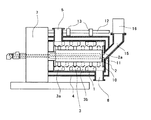
図1は、本発明の実施形態の一例を示す粉体処理装置の概略断面図である。この粉体処理装置は、図1に示されるように、ジャケット(冷却用又は加熱用媒体の流路)4に包まれた円筒形のケーシング1の中心部に、複数の板状の攪拌部材3を外周部に設けた回転軸2を備えている。攪拌部材3は、回転軸2の軸方向に対し傾斜をつけた角度で配置され、送り用攪拌部材3aと戻し用攪拌部材3bとで構成されている。送り用攪拌部材3aと戻し用攪拌部材3bとは、交互に配置されている。
ケーシング1と攪拌部材3の間には空間が設けられている。回転軸2の回転に伴い移動する攪拌部材3によってケーシング1内の処理物を攪拌処理するよう構成している。回転軸2は軸受部7によって片側で支持され、モーター等で構成される不図示の駆動部と連結している。原料投入口5はケーシング1の例えば軸受部7側端部における上部に、製品排出口6は原料投入口5に対し例えば反対の端部にあたるケーシング1の軸受部7の反対側端部における下部に設けられている。
The best mode for carrying out the present invention will be described below with reference to the drawings. Note that it is easy for a person skilled in the art to make other embodiments by changing or correcting the present invention within the scope of the claims, and these changes and modifications are included in the scope of the claims. The following description is an example of the best mode of the present invention, and does not limit the scope of the claims.
FIG. 1 is a schematic cross-sectional view of a powder processing apparatus showing an example of an embodiment of the present invention. As shown in FIG. 1, this powder processing apparatus has a plurality of plate-like stirring
A space is provided between the
上記回転軸2は軸方向の一端側(図1における左側)のみで支持され、上記ケーシング1は回転軸2の軸方向の一端側(図1における左側)でのみ開口し他端側(図1における右側)で閉塞した有底筒状に形成されている。また、ケーシング1は、攪拌部材3との間の空間を覆う作動位置(図1に示す位置)と攪拌部材3との間の空間を覆わない非作動位置(図示せず)とに回転軸2の軸方向に沿って移動可能に構成されている。回転軸2の端面部2aには拡散部材10が備えられている。
ケーシング1は、たとえばガイド棒12およびボス13によって支持され、回転軸2の軸方向に沿って移動可能とされる。また、ケーシング1には、ケーシング内での温度上昇に伴う空気の膨張による圧力を開放したり、回転軸2の軸シール部(図示せず)のシールエアを逃がしたりするために、排気管15を備える。排気管15には、装置から漏洩した粉塵飛散を防備するために、フィルタ16を備えることが好ましい。図1において、11は冷却用又は加熱用媒体の流路である。
本装置は、ケーシング1の内周部の径(図示せず)をD1とし、回転軸2の外周部の径(図示せず)をD2とすると、D1はD2の1.4〜2倍に構成することが好ましい。
The rotating
The
In this apparatus, when the diameter (not shown) of the inner peripheral portion of the
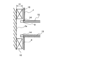
粉体処理装置において内挿管を設置したときの設置形態の一例を図2に示す。図2は、図1に示す粉体処理装置において排気管15が水平に設置されているときの拡散部材10、排気管15周辺の拡大図である。図2に示すように、拡散部材10とケーシング1の内壁は、互いに摩擦しないよう隙間9を隔てて位置する。排気管15は、貫通口8を通じて内挿管14に連通している。内挿管14は、隙間9よりも深くケーシング1内に進入するよう構成される。内挿管14の進入深さは、少なくとも隙間9の高さよりも大きく、かつ、図2にHで示す拡散部材10の高さ(拡散部材からケーシング内面へ向かう垂直方向への高さ)の10%以上の進入深さに設置される。内挿管14の進入深さは、拡散部材10の高さの20%以上であることが好ましい。内挿管14は、拡散部材の高さの10%以上、好ましくは20%以上の隙間を隔てて回転軸端面部2aに近接することが好ましい。また、この隙間は、隙間9と同じかそれ以上の大きさで構成されることが好ましい。
内挿管14の外周部および内周部は、特別な事情が無ければ、円環状に構成されることが好ましい。また、内挿管14の中心軸は、回転軸2の中心軸と同一線上にあることがさらに好ましい。
An example of the installation form when the intubation tube is installed in the powder processing apparatus is shown in FIG. FIG. 2 is an enlarged view of the periphery of the
The outer peripheral portion and the inner peripheral portion of the
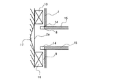
図3は、粉体処理装置における内挿管の設置形態の別例を示す。図3に示すように、内挿管14に対向する端面部2aに、窪み17が形成されている。窪み17は、円錐状に構成されることが好ましく、窪みの外形(直径)は、拡散部材10の回転半径の内径よりも小さく、かつ、内挿管の外径よりも大きく構成される。
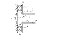
図4は、内挿管の設置形態の別例を示す。図4に示すように、内挿管はその端部がラッパ管状である内挿管14aとして構成される。内挿管14aの最大内径は、拡散部材10の回転半径の内周径よりも小さく構成されることが好ましい。窪み17が形成されていてもよく、窪み17が形成される場合には、窪み17の外径よりも小さく構成される。窪み17の外径(直径)は内挿管の最大内径よりも大きく構成される。内挿管の最大内径はD1の30〜70%程度とすることができる。また、ラッパ管における最大内径はD1の50〜85%程度とすることができる。
ラッパ管は、図4のように断面が直線状に広がるような形状に構成されてもよいし、図示しないが、断面が滑らかな曲線状(弧を描くような形状)で構成されてもよい。
FIG. 3 shows another example of the installation form of the intubation tube in the powder processing apparatus. As shown in FIG. 3, a
FIG. 4 shows another example of the installation form of the intubation. As shown in FIG. 4, the inner intubation is configured as an
The trumpet tube may be configured in a shape such that the cross section extends linearly as shown in FIG. 4 or may be configured in a curved shape (shape that draws an arc) with a smooth cross section, although not shown. .
図2ないし4に示すように内挿管を設置することにより、回転軸の端面部に設置された拡散部材とケーシングとの間にある隙間からの粉体の漏洩を抑止することができる。これは、内挿管によって、前記隙間の出口部、すなわち拡散部材の内周部側の隙間部に壁ができることで、前記隙間を流れる気流を削減するとともに、内挿管の周囲に発生する旋回流による遠心力で、前記隙間を通過した粉体の一部を、再び拡散部材部位に追いやる作用が得られるためである。
このように、隙間部に対する壁効果を、回転する拡散部材部のクリアランスの全周にわたって均等に得るために、内挿管は円筒であり、内挿管の中心が回転軸の中心軸と同一線上にくるように設置されることが好ましい。
また、内挿管が回転軸中心軸と同一線上にあることで、内挿管の周囲に、効率的に旋回流を形成することができる。
By installing the intubation tube as shown in FIGS. 2 to 4, it is possible to suppress the leakage of powder from the gap between the diffusion member installed on the end surface portion of the rotating shaft and the casing. This is because a wall is formed at the exit portion of the gap, that is, the gap portion on the inner peripheral side of the diffusion member, by the intubation, thereby reducing the airflow flowing through the gap and the swirl flow generated around the intubation tube. This is because an action of driving a part of the powder that has passed through the gap to the diffusion member portion by centrifugal force can be obtained.
Thus, in order to obtain the wall effect on the gap portion uniformly over the entire circumference of the clearance of the rotating diffusion member portion, the inner intubation is a cylinder, and the center of the inner intubation is collinear with the central axis of the rotation axis. It is preferable to be installed as described above.
Further, since the intubation is on the same line as the rotation axis central axis, a swirl flow can be efficiently formed around the intubation.
さらに、前記内挿管に対向する回転軸端面部に、円環状の窪みを設置することが好ましい。回転軸端面部に窪みを形成することで、内挿管の外周部を通過してしまった粉体が、さらに内挿管の内側方向へ進入することを抑止することができる。この窪みの作用としては複数の理由が考えられるが、例えば窪みによって回転軸端面部と内挿管の端面との距離が離れることで、内挿管端面周辺において内挿管方向へ流れる気流ベクトルの速度を低下させ、相対的に回転軸周囲に形成される旋回流の遠心力を大きくする作用が例示できる。
円環状の窪みの形状としては、例えば円筒状や、円錐状の窪みなどを挙げることができるが、特に円錐状の窪みが、円錐の周囲に粉体を排除する効果が高く、好適である。
内挿管の端部の、特に好ましい形状は、端部がラッパ管状に形成されることである。ラッパ管状に形成することで、内挿管の端部に向かって流れる粉体が、内挿管の端部に達する直前に、拡散部材近傍に追いやることができる。
Furthermore, it is preferable to install an annular recess on the end surface of the rotating shaft facing the inner tube. By forming the depression in the end surface portion of the rotating shaft, it is possible to prevent the powder that has passed through the outer peripheral portion of the inner tube from further entering the inner side of the tube. There are a number of possible reasons for the action of this depression.For example, the distance between the end surface of the rotary shaft and the end face of the intubation is increased by the depression, thereby reducing the velocity of the airflow vector flowing in the intubation direction around the end face of the intubation. The effect of relatively increasing the centrifugal force of the swirling flow formed around the rotation axis can be exemplified.
Examples of the shape of the annular recess include a cylindrical shape and a conical recess. A conical recess is particularly preferable because it has a high effect of removing powder around the cone.
A particularly preferable shape of the end portion of the intubation tube is that the end portion is formed in a trumpet shape. By forming the tube in a trumpet shape, the powder flowing toward the end of the inner intubation can be driven to the vicinity of the diffusion member immediately before reaching the end of the inner intubation.
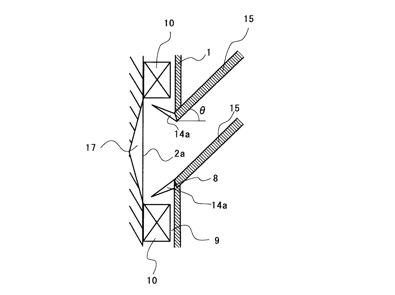
以上の構成を経てなお内挿管に達してしまった粉体を幾ばくでも捕捉するために、内挿管に連通する排気管は、水平や下向きでなく、上向きに設置されることが好ましい。図5に、排気管の好ましい設置形態を示す。排気管15の上向きの角度(θ)は、排気管15の内壁に付着した粉体が管壁から貫通口8へ落下できるよう、水平方向に対して30°以上の角度に構成されることが好ましい。また、この角度の上限は、70°程度である。この角度が大きすぎると、貫通口部における管内の気流の偏りが出てくる。言い換えれば気流の速い部位と遅い部位ができてしまい、貫通口部の気流の速い部位では粉体の流出をかえって促進してしまう。
In order to capture any amount of powder that has reached the inner intubation through the above configuration, the exhaust pipe communicating with the inner intubation is preferably installed upward rather than horizontally or downward. FIG. 5 shows a preferred installation form of the exhaust pipe. The upward angle (θ) of the
本発明の効果を実験結果によって以下に示す。
実施例1ないし5および比較例1、2
実験装置としては、図1に示した装置を用いた。実施例では、図2ないし5に示した内挿管周囲の構造を有する装置を用い、表1に示す構造の組み合わせとした。比較例では、内挿管を有しない従来形態の装置を用い、表1に示す条件で実験を行った。
その他の実験条件として、混合装置のケーシング内径を約130.8mm、仕込み体積を0.5Lとした。回転軸2の外周部の径は70mmとした。実施例においては、内挿管の最大内径および外径をそれぞれ35.7mm、42.7mmとした。このとき、拡散部材の回転内径および回転外径はそれぞれ55mm、90mmとした。
さらにラッパ管を用いる場合はラッパ管の最大内径および最大外径をそれぞれ41.6mm、48.6mmとした。このとき、拡散部材の回転内径および回転外径はそれぞれ55mm、90mmとした。さらに円錐状の窪みを使用するときは、円錐の外形は50mmとし、円錐の深さは10mmとした。
比較例においては、内挿管を有しないが、排気管と処理装置の連結部の口径(内径)は35.7mmとして、実施例における内挿管の内径と同じとした。
電気抵抗式粒度分布測定器によって測定した重量平均径D4が約5.2μmのトナー粒子を180g投入し、トナー原料1kgあたり4kWのモーター負荷(混合機の混合中の動力から、混合機の空転動力を差し引いた値を、トナー1kgあたりに換算した値)で3分間混合した。
得られた製品について、その回収率で評価した。排気管を経て外部へ漏洩する粉体原料が減少すると、製品の回収率が向上するため、回収率は高いほど優れた効果を有すると判断する。
製品の回収率は、混合装置内での付着の影響や、回収方法の影響をキャンセルするために、図1に示すフィルタ16内に捕捉された粉体の質量を、投入量180gから差し引いて回収量を求め、この回収量に基づいて製品回収率(%)を求めた。その結果を表1に示す。
The effects of the present invention are shown below by experimental results.
Examples 1 to 5 and Comparative Examples 1 and 2
As the experimental apparatus, the apparatus shown in FIG. 1 was used. In the examples, the apparatus having the structure around the intubation shown in FIGS. 2 to 5 was used, and the combinations shown in Table 1 were used. In the comparative example, an experiment was performed under the conditions shown in Table 1 using a conventional apparatus having no intubation.
As other experimental conditions, the casing inner diameter of the mixing apparatus was about 130.8 mm, and the charging volume was 0.5 L. The diameter of the outer peripheral part of the
Further, when a trumpet tube is used, the maximum inner diameter and the maximum outer diameter of the trumpet tube are 41.6 mm and 48.6 mm, respectively. At this time, the rotation inner diameter and the rotation outer diameter of the diffusion member were 55 mm and 90 mm, respectively. Further, when using a conical depression, the outer shape of the cone was 50 mm and the depth of the cone was 10 mm.
In the comparative example, the inner tube is not provided, but the diameter (inner diameter) of the connecting portion between the exhaust pipe and the processing apparatus is 35.7 mm, which is the same as the inner diameter of the inner tube in the example.
180 g of toner particles having a weight average diameter D4 measured by an electric resistance type particle size distribution measuring device of about 5.2 μm are charged and a motor load of 4 kW per 1 kg of the toner raw material (from the mixing power of the mixer to the idling power of the mixer) The value obtained by subtracting the value obtained by subtracting 1 from the toner was mixed for 3 minutes.
About the obtained product, it evaluated by the recovery rate. If the powder raw material leaking to the outside through the exhaust pipe decreases, the product recovery rate is improved. Therefore, it is determined that the higher the recovery rate, the better the effect.
The product recovery rate is determined by subtracting the mass of the powder trapped in the
また、実施例1、2と実施例3ないし5の対比から、内挿管がラッパ管であると、高い効果が得られることが確認された。さらに、実施例1と2などの対比によって、窪みを有するものがより優れていること、また、実施例4と5との対比によって、排気管は角度を持って設置されることが製品回収率の点から有効であることが確認された。
Further, from the comparison between Examples 1 and 2 and Examples 3 to 5, it was confirmed that a high effect was obtained when the inner tube was a trumpet tube. Further, the product recovery rate is that the one having a recess is superior by comparing Example 1 and 2 and the exhaust pipe is installed at an angle by comparing Example 4 and 5. From this point, it was confirmed that it was effective.
1 ケーシング
2 回転軸
2a 回転軸端面部
3 攪拌部材
3a 送り用攪拌部材
3b 戻し用攪拌部材
4 ジャケット
5 原料投入口
6 製品排出口
7 軸受部
8 貫通口
9 隙間
10 拡散部材
11 冷却用又は加熱用媒体の流路
12 ガイド棒
13 ボス
14 内挿管
14a ラッパ管状の内挿管
15 排気管
16 フィルタ
17 窪み
H 拡散部材の高さ
DESCRIPTION OF
Claims (6)
前記回転軸が軸方向の動力を伝達する側のみで支持され、
前記回転軸の端面部に拡散部材を設けてあり、
前記回転軸が軸方向の動力を伝達する側と対向するケーシング側面に、気体を排気可能な貫通口を有する粉体処理装置において、
貫通口が水平に貫通した、気体が排気可能な中空の円筒状の内挿管を設けてあり、
該内挿管が、前記回転軸の端面部と対向し、かつ前記拡散部材の内部に位置する
ことを特徴とする粉体処理装置。 A rotating shaft provided with a plurality of stirring members on the outer peripheral portion and installed horizontally, and a casing having an inner peripheral portion located at a gap with respect to the stirring member, and moves as the rotating shaft rotates. A powder processing apparatus that stirs the powder in the casing with the stirring member.
The rotating shaft is supported only on the side transmitting axial power,
A diffusing member is provided on an end surface of the rotating shaft;
In the powder processing apparatus having a through-hole through which the gas can be exhausted on the side of the casing facing the side where the rotary shaft transmits axial power,
A hollow cylindrical intubation tube through which the through-hole penetrates horizontally and gas can be exhausted is provided.
The powder processing apparatus, wherein the intubation tube is opposed to an end surface portion of the rotating shaft and is located inside the diffusion member.
The powder processing apparatus according to any one of claims 2 to 5, wherein an exhaust pipe communicating with the inner intubation is installed upward.
Priority Applications (1)
| Application Number | Priority Date | Filing Date | Title |
|---|---|---|---|
| JP2008319163A JP5163468B2 (en) | 2008-12-16 | 2008-12-16 | Powder processing equipment |
Applications Claiming Priority (1)
| Application Number | Priority Date | Filing Date | Title |
|---|---|---|---|
| JP2008319163A JP5163468B2 (en) | 2008-12-16 | 2008-12-16 | Powder processing equipment |
Publications (2)
| Publication Number | Publication Date |
|---|---|
| JP2010142672A true JP2010142672A (en) | 2010-07-01 |
| JP5163468B2 JP5163468B2 (en) | 2013-03-13 |
Family
ID=42563665
Family Applications (1)
| Application Number | Title | Priority Date | Filing Date |
|---|---|---|---|
| JP2008319163A Expired - Fee Related JP5163468B2 (en) | 2008-12-16 | 2008-12-16 | Powder processing equipment |
Country Status (1)
| Country | Link |
|---|---|
| JP (1) | JP5163468B2 (en) |
Families Citing this family (1)
| Publication number | Priority date | Publication date | Assignee | Title |
|---|---|---|---|---|
| KR100813388B1 (en) | 2005-11-24 | 2008-03-12 | 주식회사 엘지화학 | Acrylic pressure sensitive adhesive compositions |
Citations (2)
| Publication number | Priority date | Publication date | Assignee | Title |
|---|---|---|---|---|
| JPH1076150A (en) * | 1996-09-03 | 1998-03-24 | Mitsubishi Heavy Ind Ltd | Dust stop of pressure kneader |
| JP2005270955A (en) * | 2004-02-23 | 2005-10-06 | Hosokawa Funtai Gijutsu Kenkyusho:Kk | Treatment apparatus and powder treatment method |
-
2008
- 2008-12-16 JP JP2008319163A patent/JP5163468B2/en not_active Expired - Fee Related
Patent Citations (2)
| Publication number | Priority date | Publication date | Assignee | Title |
|---|---|---|---|---|
| JPH1076150A (en) * | 1996-09-03 | 1998-03-24 | Mitsubishi Heavy Ind Ltd | Dust stop of pressure kneader |
| JP2005270955A (en) * | 2004-02-23 | 2005-10-06 | Hosokawa Funtai Gijutsu Kenkyusho:Kk | Treatment apparatus and powder treatment method |
Also Published As
| Publication number | Publication date |
|---|---|
| JP5163468B2 (en) | 2013-03-13 |
Similar Documents
| Publication | Publication Date | Title |
|---|---|---|
| US8485459B2 (en) | Intense vortex dryer, comminutor and reactor | |
| CN102644625B (en) | The turbofan of air-conditioning system | |
| CN204770462U (en) | Handle device with cooling casting sand | |
| CN101270761A (en) | Centrifugal blower and air conditioner having same | |
| KR101598165B1 (en) | Pit barrel pump and method for incorporating same | |
| EP2923766A1 (en) | Media-stirring pulverizer of internal classifier type | |
| CN101980427A (en) | Slip ring ventilation cooling system structure | |
| CN118601941A (en) | Slurry pump inlet components | |
| JP5163468B2 (en) | Powder processing equipment | |
| JP2011189310A (en) | Liquid-powder mixing apparatus, and method for producing liquid-powder mixture | |
| CN101319681A (en) | Vortex blower | |
| CN205119388U (en) | Air purifier | |
| CN107634609B (en) | Rotor cooling system and method of magnetic suspension high-speed motor direct-connected atomizer | |
| KR102108457B1 (en) | Moist air stream generator | |
| JP5857042B2 (en) | Double flow centrifugal pump | |
| US10792676B2 (en) | Suction device and drive device | |
| CN206082858U (en) | Novel immediately, grind dynamic and static combination formula selection powder machine | |
| CN107803264A (en) | It is a kind of to disturb the equipment that enhancing is crushed and surface is modified | |
| JP2021181038A (en) | Agitator | |
| JP2008036567A (en) | Powder treatment apparatus and toner particle manufacturing method | |
| JP2003260346A (en) | High-speed agitation type disperser | |
| CN209222056U (en) | A fluidized bed and fluidized bed granulation separation system | |
| CN106032814A (en) | Centrifugal fan | |
| CN102527639B (en) | Lower air-out type high-efficient powder concentrator | |
| CN209244924U (en) | Air guide ring, fan and water heater |
Legal Events
| Date | Code | Title | Description |
|---|---|---|---|
| A621 | Written request for application examination |
Free format text: JAPANESE INTERMEDIATE CODE: A621 Effective date: 20111014 |
|
| A977 | Report on retrieval |
Free format text: JAPANESE INTERMEDIATE CODE: A971007 Effective date: 20121025 |
|
| TRDD | Decision of grant or rejection written | ||
| A01 | Written decision to grant a patent or to grant a registration (utility model) |
Free format text: JAPANESE INTERMEDIATE CODE: A01 Effective date: 20121120 |
|
| A61 | First payment of annual fees (during grant procedure) |
Free format text: JAPANESE INTERMEDIATE CODE: A61 Effective date: 20121203 |
|
| FPAY | Renewal fee payment (event date is renewal date of database) |
Free format text: PAYMENT UNTIL: 20151228 Year of fee payment: 3 |
|
| R151 | Written notification of patent or utility model registration |
Ref document number: 5163468 Country of ref document: JP Free format text: JAPANESE INTERMEDIATE CODE: R151 |
|
| FPAY | Renewal fee payment (event date is renewal date of database) |
Free format text: PAYMENT UNTIL: 20151228 Year of fee payment: 3 |
|
| LAPS | Cancellation because of no payment of annual fees |