JP2010142615A - Toothpick utilizing air pressure - Google Patents
Toothpick utilizing air pressure Download PDFInfo
- Publication number
- JP2010142615A JP2010142615A JP2008326615A JP2008326615A JP2010142615A JP 2010142615 A JP2010142615 A JP 2010142615A JP 2008326615 A JP2008326615 A JP 2008326615A JP 2008326615 A JP2008326615 A JP 2008326615A JP 2010142615 A JP2010142615 A JP 2010142615A
- Authority
- JP
- Japan
- Prior art keywords
- air
- air cylinder
- control unit
- cylinder
- compressed air
- Prior art date
- Legal status (The legal status is an assumption and is not a legal conclusion. Google has not performed a legal analysis and makes no representation as to the accuracy of the status listed.)
- Pending
Links
- 235000010585 Ammi visnaga Nutrition 0.000 title claims abstract description 26
- 244000153158 Ammi visnaga Species 0.000 title claims abstract description 26
- 230000007246 mechanism Effects 0.000 claims abstract description 18
- 238000003825 pressing Methods 0.000 claims abstract description 7
- 238000007599 discharging Methods 0.000 claims abstract description 4
- 229910052751 metal Inorganic materials 0.000 claims description 7
- 239000002184 metal Substances 0.000 claims description 7
- 238000000465 moulding Methods 0.000 claims description 5
- 230000000903 blocking effect Effects 0.000 claims description 2
- 210000000214 mouth Anatomy 0.000 abstract description 16
- 239000002689 soil Substances 0.000 abstract 1
- 238000004140 cleaning Methods 0.000 description 14
- 241000628997 Flos Species 0.000 description 9
- 230000000694 effects Effects 0.000 description 5
- 238000004519 manufacturing process Methods 0.000 description 4
- 238000000034 method Methods 0.000 description 4
- 239000000835 fiber Substances 0.000 description 3
- 230000036541 health Effects 0.000 description 3
- XLYOFNOQVPJJNP-UHFFFAOYSA-N water Substances O XLYOFNOQVPJJNP-UHFFFAOYSA-N 0.000 description 3
- 239000004677 Nylon Substances 0.000 description 2
- 239000012530 fluid Substances 0.000 description 2
- 229920001778 nylon Polymers 0.000 description 2
- 229910052710 silicon Inorganic materials 0.000 description 2
- 239000010703 silicon Substances 0.000 description 2
- 229910000838 Al alloy Inorganic materials 0.000 description 1
- VYZAMTAEIAYCRO-UHFFFAOYSA-N Chromium Chemical compound [Cr] VYZAMTAEIAYCRO-UHFFFAOYSA-N 0.000 description 1
- 229910000617 Mangalloy Inorganic materials 0.000 description 1
- ZOKXTWBITQBERF-UHFFFAOYSA-N Molybdenum Chemical compound [Mo] ZOKXTWBITQBERF-UHFFFAOYSA-N 0.000 description 1
- 229910000831 Steel Inorganic materials 0.000 description 1
- 230000004913 activation Effects 0.000 description 1
- 230000003044 adaptive effect Effects 0.000 description 1
- 230000006835 compression Effects 0.000 description 1
- 238000007906 compression Methods 0.000 description 1
- 238000010276 construction Methods 0.000 description 1
- 238000011109 contamination Methods 0.000 description 1
- 230000003247 decreasing effect Effects 0.000 description 1
- 230000006866 deterioration Effects 0.000 description 1
- 238000010586 diagram Methods 0.000 description 1
- 230000003670 easy-to-clean Effects 0.000 description 1
- 235000013305 food Nutrition 0.000 description 1
- 230000002496 gastric effect Effects 0.000 description 1
- 210000004195 gingiva Anatomy 0.000 description 1
- 230000007774 longterm Effects 0.000 description 1
- 239000000463 material Substances 0.000 description 1
- 230000004048 modification Effects 0.000 description 1
- 238000012986 modification Methods 0.000 description 1
- 229910052750 molybdenum Inorganic materials 0.000 description 1
- 239000011733 molybdenum Substances 0.000 description 1
- 230000000149 penetrating effect Effects 0.000 description 1
- 239000010959 steel Substances 0.000 description 1
Images


Landscapes
- Brushes (AREA)
Abstract
Description
本発明は、たとえば空気圧利用トゥースピックに係り、特に圧縮空気が充填された容器から、ノズルを介して圧縮空気を噴出させ、それによって歯間や歯茎を洗浄する装置に関する。 The present invention relates to, for example, a pneumatic toothpick, and more particularly, to an apparatus for jetting compressed air from a container filled with compressed air through a nozzle, thereby cleaning the teeth and gums.
従来より、歯間の汚れを効果的に除去して洗浄する用具として、歯間ブラシやフロスなどがあった。しかし、これらは汚れを除去するために歯間に直接挿入しなければならず、その結果、歯茎等が傷つき、出血する可能性がある。また、個人によって異なる歯の形状や歯並びにより、歯間ブラシやフロスなどでは、汚れの付着箇所にうまく到達させることが難しく、フロスなどを誤って歯の先端にこすりつけてしまうと、フロスの繊維が切断され、繊維の切片が口腔内に残留することもあった。さらに同一個人の口腔内においても、各歯間の幅は異なるため、効果的に歯間の汚れを除去するためには、それぞれの歯の個所に合わせて用具を使用する必要があった。 Conventionally, there have been interdental brushes, floss, and the like as tools for effectively removing dirt between teeth and cleaning them. However, these have to be inserted directly between the teeth in order to remove the dirt, with the result that the gums and the like can be damaged and bleed. In addition, it is difficult to reach the location where the dirt adheres well with interdental brushes and floss, etc., depending on the individual tooth shape and teeth, and if the floss is mistakenly rubbed to the tip of the tooth, the fiber of the floss will It was cut and fiber sections could remain in the mouth. Furthermore, since the width between each tooth is different even in the oral cavity of the same individual, it is necessary to use a tool in accordance with the location of each tooth in order to effectively remove dirt between the teeth.
一方、繊維やブラシなどを使用せずに、ノズルの先端から歯間に空気や水を噴出することによって歯間や歯茎を洗浄するジェット流口腔洗浄装置が知られている。しかし、ジェット流口腔洗浄装置は、空気を圧縮させるためのコンプレッサ、さらにコンプレッサとノズルを繋ぐチューブなどを必要とするため、装置が大型になりやすく、かつ高価であり、歯科医院等の専門施設での利用が主なものであった。 On the other hand, there is known a jet-flow oral cleaning device that cleans the teeth and gums by ejecting air or water between the teeth from the tip of the nozzle without using fibers or brushes. However, since a jet flow oral cleaning device requires a compressor for compressing air and a tube connecting the compressor and the nozzle, the device tends to be large and expensive, and it is a specialized facility such as a dental clinic. The main use was.
この問題の解決手段として、特許文献1には、ボンベ中に圧縮して貯蔵されている圧縮流体をノズルから吐出させることにより、ジェット流で歯垢や歯間に挟まった食べ物の滓を除去するようにした装置が開示されている。
特許文献1の装置では、気密にかつ往復動可能に嵌合したピストンを手動で往復動させることで圧縮空気を空気ボンベ内に充填させるため、コンプレッサは不要であり、比較的小規模な装置の実現が可能となる。
In the device of
しかしこの装置では、空気ボンベやピストン、空気圧縮ポンプ等が本体洗浄具内に配置され、かつ空気を圧縮するためのシリンダも備えられており、このため装置本体の構造が複雑であった。さらに圧縮空気の製造は装置内に具備されるピストンの往復動によって行なうため、口腔内の洗浄時に圧縮空気の製造と排出を繰り返さなければならず、時間と労力を要するものであった。一般に口腔内、歯間、及び歯茎の洗浄具は子供から高齢者、ペットまで幅広い対象での使用が想定されるものであり、それゆえに操作における容易性はさらに追求すべき問題であった。 However, in this apparatus, an air cylinder, a piston, an air compression pump, and the like are arranged in the main body cleaning tool, and a cylinder for compressing air is also provided, so that the structure of the apparatus main body is complicated. Furthermore, since the production of compressed air is performed by reciprocating movement of a piston provided in the apparatus, the production and discharge of compressed air must be repeated at the time of cleaning in the oral cavity, which requires time and labor. In general, oral, interdental, and gum cleaning tools are supposed to be used in a wide range of subjects from children to the elderly and pets. Therefore, ease of operation has been a problem to be further pursued.
本発明の主たる目的は、対象者の年齢や、口腔内、歯間、及び歯茎の形状・寸法の相違によらず、またペットに対してであっても、効果的に歯間の汚れを除去できるだけでなく、軽量で携帯可能であり、操作性の高い空気圧利用のトゥースピックを提供することである。 The main object of the present invention is to remove dirt between teeth effectively, even for pets, regardless of the age of the subject, differences in oral cavity, interdental, and gum shape and dimensions. It is not only possible to provide a toothpick that uses light pressure but is light and portable and has high operability.
かかる目的を達成するために、本発明に係る空気圧利用トゥースピックは、圧縮空気があらかじめ貯留されたエアボンベと、前記エアボンベに対して、軸部に配置されたニードルが押圧または螺合を含む接続によって該エアボンベと嵌合して気密に接続し、前記貯留された圧縮空気を吐出/遮断させる動作を制御するON/OFF切り替えスイッチ、及び該圧縮空気の吐出量を調節するエア量調節機構が設けられたエア制御部と、前記エア制御部に接続可能に構成され、前記エアボンベから供給された該圧縮空気を吐出するエアノズルとを備えて構成される。 In order to achieve such an object, the pneumatic tooth pick according to the present invention includes an air cylinder in which compressed air is stored in advance and a connection in which a needle disposed in a shaft portion includes pressing or screwing with the air cylinder. An ON / OFF switch for controlling the operation of fitting and airtightly connecting the air cylinder and discharging / blocking the stored compressed air, and an air amount adjusting mechanism for adjusting the discharge amount of the compressed air are provided. The air control unit is configured to be connectable to the air control unit, and includes an air nozzle that discharges the compressed air supplied from the air cylinder.
この場合において、エアボンベは、金属により被覆される一体成型から成り、該エアボンベ端部に位置する前記圧力空気の吐出口の断面は、他側面に比べて薄肉で形成され、前記エア制御部の軸部に配置されたニードルが貫通することで開封し、該圧力空気が吐出されるような構成とすることも可能である。 In this case, the air cylinder is formed by integral molding covered with metal, and the cross section of the pressure air discharge port located at the end of the air cylinder is formed thinner than the other side surface, and the shaft of the air control unit It is also possible to adopt a configuration in which the needle disposed in the part is opened by passing therethrough and the pressurized air is discharged.
ここで、エアボンベ本体を一体に成型する部材として、マンガン鋼、クロムモリブデン鋼、およびアルミニウム合金を含む金属を用いることができる。エアボンベ内部には圧縮空気が充填されており、エアボンベ上端に配置される吐出部は、圧縮空気充填時において内圧に耐えうる程度にエアボンベ他側面よりも薄肉で、かつ本体部材と同一部材で密閉されている。 Here, as a member for integrally molding the air cylinder main body, a metal including manganese steel, chrome molybdenum steel, and an aluminum alloy can be used. The air cylinder is filled with compressed air, and the discharge part arranged at the upper end of the air cylinder is thinner than the other side of the air cylinder and sealed with the same member as the main body so that it can withstand the internal pressure when filling with compressed air. ing.
このような構成により、エア制御部の軸方向一端に配置されたニードルが押圧または螺合を含む接続によって、エアボンベ吐出部の金属より成る密閉部分を貫通して嵌合し、エアボンベとエア制御部は気密可能に接続する。エア制御部の一端から突出するニードルは中空構造を成すため、これによってエア制御部は、軸部上においてニードルが配置される一端と反対側の端に設けたエアノズルとの接続部が連通し、エアボンベから吐出される圧縮空気を流動させることが可能となる。したがって、圧縮空気を充填した容器に管状ノズルを挿入することで圧縮空気を噴出させる機構を、本体に配置されたON/OFF機構、及び強弱の調節機構を介して、本体制御部に(利用者が)信号を入力するだけで歯間、または歯茎を洗浄することができることになるため、操作性が高い。さらに、空気圧の供給源としてエアボンベを用いるため、軽量で携帯可能である。 With such a configuration, the needle disposed at one end in the axial direction of the air control unit is fitted through the sealed portion made of metal of the air cylinder discharge unit by connection including pressing or screwing, and the air cylinder and the air control unit Connect in an airtight manner. Since the needle protruding from one end of the air control unit has a hollow structure, the air control unit communicates with a connection portion with an air nozzle provided at an end opposite to one end where the needle is disposed on the shaft portion, It becomes possible to flow the compressed air discharged from the air cylinder. Therefore, a mechanism for ejecting compressed air by inserting a tubular nozzle into a container filled with compressed air is connected to the main body control unit via the ON / OFF mechanism and strength adjustment mechanism arranged on the main body (user ) Since interdental or gums can be cleaned only by inputting a signal, operability is high. Further, since an air cylinder is used as a pneumatic supply source, it is lightweight and portable.
また、前記目的を達成するために、本発明に係る空気圧利用トゥースピックにおいて、エア制御部は、エアボンベから吐出する圧縮空気の吐出実行に関するON/OFF切り替えスイッチ、及び圧縮空気の吐出量を調節するエア量調節機構を備えており、切り替えスイッチ、及びエア量調節機構に入力された信号によって、エア制御部は電力、またはスイッチ押下による作動力を含む公知のシステムを利用してエアボンベの吐出部からの圧縮空気吐出を実行/停止、及び圧縮空気の吐出量の増減を行うことができる。 In order to achieve the above object, in the pneumatic tooth pick according to the present invention, the air control unit adjusts an ON / OFF switch for executing discharge of compressed air discharged from the air cylinder and a discharge amount of the compressed air. The air control unit has an air amount adjusting mechanism, and the air control unit uses a known system including an electric power or an operation force by pressing the switch, depending on a signal input to the changeover switch and the air amount adjusting mechanism, from the discharge unit of the air cylinder. The compressed air discharge can be executed / stopped and the discharge amount of the compressed air can be increased / decreased.
かかる構成により、エア制御部に配置される、ON/OFF切り替えスイッチ、及び圧縮空気の吐出量を調節するエア量調節機構への信号入力は、いずれも片手で実行できるため、空いている片手で手鏡の携行、または口唇の拡張などが可能となり、より効率的な口腔、または歯茎の洗浄につながる。さらに、本発明は本体部分の構造が簡素であるため、不慣れな者でも簡単に操作することができ、かつ、本体自体の手入れ及び洗浄も簡便であり、高い衛生性を確保することができる。 With this configuration, the signal input to the ON / OFF switch and the air amount adjusting mechanism for adjusting the discharge amount of compressed air, which are arranged in the air control unit, can be executed with one hand. Carrying a hand mirror or expanding the lips is possible, leading to more efficient oral cavity or gum cleaning. Furthermore, since the structure of the main body portion of the present invention is simple, even an inexperienced person can easily operate it, and the main body itself can be easily maintained and cleaned, and high hygiene can be ensured.
さらに、前記エア制御部は、軸部一端側に前記ニードルが配置され、軸部他端側に気密かつ着脱可能に前記エアノズルが接続されて構成され、該エアボンベから吐出される前記圧縮空気は、該ニードル、及び該エア制御部を経由して該エアノズルとの接続部に流動し、該エアノズル他端から噴射されるような構成とすることもできる。 Further, the air control unit is configured such that the needle is disposed on one end side of the shaft portion and the air nozzle is connected to the other end side of the shaft portion so as to be airtight and detachable, and the compressed air discharged from the air cylinder is A configuration may also be adopted in which the fluid flows to a connection portion with the air nozzle via the needle and the air control portion and is ejected from the other end of the air nozzle.
かかる構成により、エアボンベから吐出される圧縮空気は、エア制御部の軸方向一端に配置されるニードル、及び他端に配置されるエアノズルとの接続部において気密に接続するため、エアボンベ吐出部においてニードルが貫通した穴から噴出する圧縮空気は、その空気圧による気流の強さを損なうことなく、接続部へ流動することが可能となる。 With this configuration, the compressed air discharged from the air cylinder is hermetically connected at the connection portion between the needle disposed at one end of the air control unit in the axial direction and the air nozzle disposed at the other end. Compressed air that is ejected from a hole that passes through can flow to the connecting portion without impairing the strength of the airflow due to the air pressure.
また、上記構成において、エア制御部は、接続部において圧縮空気を吐出するエアノズルと着脱可能に接続し、かつ接続部において、エアノズルと取替可能なアタッチメントを装着し得ることを特徴とする。 In the above configuration, the air control unit can be detachably connected to an air nozzle that discharges compressed air at the connection portion, and an attachment that can be replaced with the air nozzle can be attached to the connection portion.
かかる構成により、アタッチメントとして種々の形状、材料、構造に係るものを選択することで、様々な態様、状況に応じた口腔内の洗浄を可能とする。 With this configuration, it is possible to clean the oral cavity according to various aspects and situations by selecting attachments that have various shapes, materials, and structures.
本発明に係る空気圧利用トゥースピックによれば、あらかじめ圧縮空気が貯留されたエアボンベに対し、エア制御部に配置されたニードルを嵌合させることによって圧縮空気を噴出させ、その空気圧によって歯間、または歯茎を含む口腔内の洗浄を行うことができる。 According to the air pressure-use toothpick according to the present invention, compressed air is ejected by fitting a needle disposed in an air control unit to an air cylinder in which compressed air is stored in advance, and the air pressure causes interdental or Cleaning of the oral cavity including gums can be performed.
さらに詳細には、圧縮空気を充填した容器に管状ノズルを挿入することで圧縮空気を噴出させる機構を、本体に配置されたON/OFF機構、及び強弱の調節機構を介して、本体制御部に(利用者が)信号を入力するだけで歯間、または歯茎を洗浄することができることになるため、操作性が高い。さらに、空気圧の供給源としてエアボンベを用いるため、軽量で携帯可能である。 More specifically, a mechanism for ejecting compressed air by inserting a tubular nozzle into a container filled with compressed air is connected to the main body control unit via an ON / OFF mechanism disposed on the main body and a strength adjustment mechanism. The operability is high because the teeth or gums can be cleaned only by inputting a signal (by the user). Further, since an air cylinder is used as a pneumatic supply source, it is lightweight and portable.
さらに、本発明による空気圧利用トゥースピックは、本体部分の構成が簡素である。歯茎や歯の健康維持は、子供から高齢者、さらにはペットまで共通の課題であり、不慣れな者であっても簡単に扱うことができ、かつ使用時にも重量等による負担をかけずに効果的に操作できることは本発明の簡素な構造により得られる効果である。 Furthermore, the pneumatic toothpick according to the present invention has a simple configuration of the main body portion. Maintaining the health of gums and teeth is a common issue for children, the elderly, and even pets, and can be easily handled even by unfamiliar people, and is effective without burden due to weight, etc. It is an effect obtained by the simple structure of the present invention that it can be operated manually.
また、構造が簡素であることは、操作の簡便さのみでなく、本体の手入れや洗浄がしやすいという効果もある。特に、本発明のように口腔において使用する器具に関しては、高い衛生性を維持できることは必要不可欠な要素である。本発明による空気圧トゥースピックは、使用するのは水ではなく圧縮空気であるため、水を使用する口腔洗浄具と比較して水垢等の汚れが付着する可能性は低く、さらにエアボンベは、内部に充填された圧縮空気が使用されることでなくなった場合、新しいエアボンベのカートリッジと交換して使用するため、長期使用による汚れや劣化を避けることができる。 In addition, the simplicity of the structure has an effect that not only the operation is easy, but also the main body is easy to clean and clean. In particular, with respect to a device used in the oral cavity as in the present invention, it is an indispensable element that high hygiene can be maintained. Since the pneumatic toothpick according to the present invention uses compressed air instead of water, it is less likely to be contaminated with dirt or the like than an oral cleaning device using water. When the filled compressed air is no longer used, it is used by replacing it with a new air cylinder cartridge, so that contamination and deterioration due to long-term use can be avoided.
また、本発明によれば、エアボンベは金属による一体成型から成り、エアボンベ上端に位置する圧力空気の吐出部は、他側面に比べて薄肉で形成され、エア制御部の軸部に配置されたニードルが貫通することで開封し、圧力空気が吐出されることを特徴とするため、本発明は、本体を構成するエアボンベの製造において、多くの部品や部材を必要とすることなく、大量に、かつ安価な製造が可能となる。 Further, according to the present invention, the air cylinder is formed by integral molding with a metal, and the discharge portion of the pressurized air located at the upper end of the air cylinder is formed thinner than the other side surface, and is a needle disposed on the shaft portion of the air control unit In the manufacture of the air cylinder constituting the main body, the present invention is a large amount without requiring many parts and members. Inexpensive production becomes possible.
また、本発明によれば、エア制御部は、軸部一端側にニードルを配置し、かつ軸部他端側に気密かつ着脱可能にエアノズルを接続し、エアボンベから吐出される圧縮空気は、ニードル、及びエア制御部を経由してエア制御部及びエアノズルの接続部に流動し、エアノズル他端から噴射されるため、エアボンベからニードルを通じて吐出された圧縮空気は、空気圧によって発生した強い気流が、エア制御部の軸方向直線上に配置されたニードル、さらに接続部へと流動するため、気流の強さを損なうことなく、口腔へと噴出することが可能となる。 Further, according to the present invention, the air control unit has a needle disposed on one end side of the shaft portion, an air nozzle is connected to the other end side of the shaft portion in an airtight and detachable manner, and the compressed air discharged from the air cylinder is a needle The compressed air discharged from the air cylinder through the needle is a strong air current generated by the air pressure, and flows to the connection portion of the air control unit and the air nozzle via the air control unit. Since it flows to the needle arranged on the straight line in the axial direction of the control unit and further to the connecting portion, it can be ejected to the oral cavity without impairing the strength of the airflow.
さらに、本発明によれば、エア制御部は、接続部において圧縮空気を吐出するエアノズルと着脱可能に接続し、かつ接続部において、エアノズルと取替可能なアタッチメントを装着し得るので、口腔内、さらには歯の形や歯間の構造は個人差があるところ、また、口腔洗浄具を使用する際の口腔内の状態によっても、必要とされる洗浄具の形状や効果は様々であるところ、本発明では、エアノズルと取替可能なアタッチメントとして場合や使用状況に応じて様々な種類のものを選択使用することができ、これによってさらに口腔内の適応的、効果的な洗浄効果が期待できる。 Furthermore, according to the present invention, the air control unit can be detachably connected to the air nozzle that discharges compressed air at the connection portion, and the attachment portion can be equipped with an attachment that can be replaced with the air nozzle. Furthermore, there are individual differences in the shape of the teeth and the structure between the teeth, and the required shape and effect of the cleaning tool varies depending on the state of the oral cavity when using the oral cleaning tool. In the present invention, various types of attachments that can be replaced with air nozzles can be selected and used in accordance with the case and usage conditions, and thereby, an adaptive and effective cleaning effect in the oral cavity can be expected.
以下、図面を参照して本発明を実施するための最良の形態について説明する。なお、以下では、本発明の目的を達成するための説明に必要な範囲を模式的に示し、本発明の当部分の説明に必要な範囲を主に説明することとし、説明を省略する箇所については公知技術によるものとする。 The best mode for carrying out the present invention will be described below with reference to the drawings. In the following, the range necessary for the description for achieving the object of the present invention is schematically shown, and the range necessary for the description of this part of the present invention will be mainly described. Are according to known techniques.
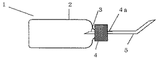
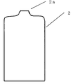
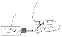
図1は本発明の第1の実施形態に係る空気圧利用トゥースピックの部分横断面図、図2はかかるエアボンベの縦断面図、図3はかかるエアボンベにエア制御部を嵌合する際の部分横断面図、図4は本発明の第1の実施形態に係るエア制御部の拡大部分横断面図、図5は本発明の第1の実施形態に係る空気圧利用トゥースピックを用いて、口腔内を洗浄している状態を示す部分縦断面図を、それぞれ示している。 FIG. 1 is a partial cross-sectional view of a pneumatic toothpick according to a first embodiment of the present invention, FIG. 2 is a vertical cross-sectional view of such an air cylinder, and FIG. 3 is a partial cross-section when an air control unit is fitted to such an air cylinder. FIG. 4 is an enlarged partial cross-sectional view of the air control unit according to the first embodiment of the present invention, and FIG. 5 is a diagram illustrating the intraoral area using the pneumatic tooth pick according to the first embodiment of the present invention. Partial vertical sectional views showing a state of cleaning are respectively shown.
図1から図5において、本発明の第1の実施形態に係る空気圧利用トゥースピック1は、エアボンベ2と、ニードル3と、エア制御部4と、エアノズル5を備えて構成されている。
1 to 5, the pneumatic-
エアボンベ2には、内部にあらかじめ圧縮空気6が充填されており、かつエアボンベ本体は金属による一体成型によって形成されている。エアボンベ端部(たとえば上端)に位置する圧縮空気の吐出部2aは、内部に充填された圧縮空気6の内圧に耐えうる程度に薄肉に形成され、かつエアボンベ2を構成する他側面と同一部材で形成される。
The
さらに、エアボンベ2の吐出部2aにエア制御部4の軸方向一端に設けられたニードルがエアボンベ2と接続して吐出部2aを形成する薄肉の金属面を貫通する。この際、エアボンベ2及びエア制御部4との接続方法は、押圧、螺合、またはその組み合わせを含む公知の技術によって成されることが可能であり、エアボンベ2の吐出部2aはエア制御部4と気密及び水密に嵌合する。
Further, a needle provided at one end of the
エア制御部4の軸方向一端から突出して配置されるニードル3は、中空構造を成し、かつエア制御部4の軸方向他端に配置される接続部4aと連通しているため、エアボンベ2内部に充填された圧縮空気6は、吐出部2aを貫通したニードル3からエア制御部4の軸部、さらに接続部4aへ、圧縮空気6の空気圧による気流の強さを損なうことなく流動することが可能となる。
The
図4は、エア制御部4を拡大して図示したものである。4bはエアボンベ2内部からニードル3内部、さらにエア制御部4の軸部を通過する圧縮空気6の流動を実行/停止するON/OFF切り替えスイッチである。4cは、圧縮空気6の吐出量を調節するエア量調節機構である。ON/OFF切り替えスイッチ4b、エア量調節機構4cへの信号入力は、電力、またはスイッチ押下による作動力を含む公知のシステムを利用し、かつ、何れも片手で実行可能である。
FIG. 4 is an enlarged view of the
エアボンベ2内部から吐出した圧縮空気6は、エアボンベ2に嵌合されエアボンベ2内部に挿入されたニードル内部を通り、エア制御部4軸部に到達してさらに接続部4aへと流動する。接続部4aは中空構造を成し、エアノズル5と嵌合、または螺合、またはその組み合わせを含む公知の技術によって気水密可能に接続する。接続部4aと接続するエアノズル5の一端から流入した圧縮空気6は、エアノズル5の他端から噴出する。
The compressed air 6 discharged from the inside of the
図1において、エアボンベ2内の圧縮空気が消費されて無くなった場合には、エアボンベ2とエア制御部4との接続を解除し、新しいエアボンベのカートリッジに交換するだけで使用を再開することができる。その際の機能及び操作は上記と同様であるため、説明を省略する。
In FIG. 1, when the compressed air in the
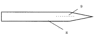
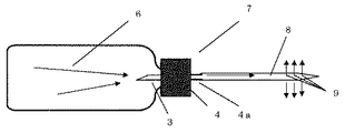
図6及び図7は、本発明の第2の実施形態に係る空気圧利用トゥースピック7を図示したものであり、詳細には、図6は本発明の第2の実施形態に係るフロス型アタッチメントの平面図を、図7はかかるフロス型アタッチメントを取り付けた際の部分縦断面図を、それぞれ示す。図1において、接続部4aからエアノズル5を取り外し、フロス型アタッチメント8を接続部4aに嵌合して組み付ける。フロス型アタッチメント8は、ナイロン、及びシリコンを含む軟質部材により内空構造で構成され、表面上に多数の微細な空気孔9が設けられている。フロス型アタッチメント8を歯間に挿入して空気圧利用トゥースピック7を操作すると、エアボンベ2内部の圧縮空気6はニードル3に流入してエア制御部4軸部を通過し、接続部4aからフロス型アタッチメント8内を流動して空気孔9から噴射される。フロス型アタッチメント8が軟質部材で構成されているため、口腔内を傷つける恐れもなく安全に、かつエアノズル5よりもさらに細かい部分を効果的に洗浄することが可能となる。
6 and 7 illustrate a pneumatic-based
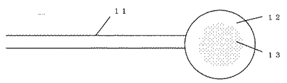
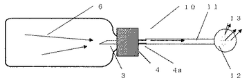
図8及び図9は、本発明第3の実施形態に係る空気圧利用トゥースピック10を図示したものであり、詳細には、図8は本発明の第3の実施形態に係るエアシャワー用アタッチメントの平面図を、図9はかかるエアシャワー用アタッチメントを取り付けた際の部分縦断面図を、それぞれ示す。図1において、接続部4aからエアノズル5を取り外し、エアシャワー用アタッチメント11を接続部4aに嵌合して組み付ける。エアシャワー型アタッチメント11は、ナイロン、及びシリコンを含む軟質部材により中空構造を成し、エアシャワーヘッド部12中心から同心円状に空気孔13が設けられている。エアシャワー用アタッチメント11を口腔に向けて空気圧利用トゥースピック10を操作すると、エアボンベ2内部の圧縮空気6はニードル3に流入してエア制御部4軸部を通過し、接続部4aからエアシャワー用アタッチメント11内を流動してエアシャワーヘッド部表面上の空気孔13から噴射される。圧縮空気の空気圧による気流が歯肉に直接噴射されることによって、歯肉のマッサージ効果が得られる。
8 and 9 illustrate a pneumatic-
なお、本発明は上述した実施形態に限定されるものではなく、本発明の主旨を逸脱しない範囲内で種々変更して実施することが可能である。また、上述したものは本願に係る技術思想を具現化するための実施形態の一例を示したにすぎないものであり、他の実施形態でも本願に係る技術思想を適用することが可能である。 Note that the present invention is not limited to the above-described embodiments, and various modifications can be made without departing from the spirit of the present invention. Moreover, what was mentioned above only showed an example of embodiment for embodying the technical idea which concerns on this application, and the technical idea which concerns on this application is applicable also to other embodiment.
本発明によれば、あらかじめ圧縮空気が貯留されたエアボンベに対し、エア制御部に配置されたニードルを嵌合させることによって圧縮空気を噴出させ、その空気圧によって歯間、または歯茎を含む口腔内の洗浄を行うことができるものである。このとき、圧縮空気を充填した容器に管状ノズルを挿入することで圧縮空気を噴出させる機構を、本体に配置されたON/OFF機構、及び強弱の調節機構を介して、本体制御部に(利用者が)信号を入力するだけで歯間、または歯茎を洗浄することができることになるため、操作性が高いだけでなく、空気圧の供給源としてエアボンベを用いるため、軽量で携帯可能である。したがって、健康や人間生活にかかわるあらゆる産業の活性化に大きな有益性をもたらすものである。詳細には、建設業、観光業、ペット産業、健康器具産業、宇宙産業、機械産業、ゲーム機業等にも広く応用される可能性を有している。 According to the present invention, compressed air is ejected by fitting a needle disposed in an air control unit to an air cylinder in which compressed air is stored in advance, and the air pressure between the teeth or the oral cavity including the gums is injected. It can be washed. At this time, a mechanism for ejecting compressed air by inserting a tubular nozzle into a container filled with compressed air is applied to the main body control unit via an ON / OFF mechanism and strength adjustment mechanism arranged on the main body (utilization). Therefore, not only is the operability high, but the air cylinder is used as the air pressure supply source, so that it is lightweight and portable. Therefore, it brings great benefits to the activation of all industries related to health and human life. Specifically, it has the potential to be widely applied to the construction industry, tourism industry, pet industry, health appliance industry, space industry, machine industry, game machine industry, and the like.
1 空気圧利用トゥースピック
2 エアボンベ
3 ニードル
4 エア制御部
4a 接続部
4b ON/OFF切り替えスイッチ
4c エア量調節機構
5 エアノズル
6 圧力空気
7 空気圧利用トゥースピック
8 フロス型アタッチメント
9 空気孔
10 空気圧利用トゥースピック
11 エアシャワー用アタッチメント
12 エアシャワーヘッド部
13 空気孔
DESCRIPTION OF
Claims (4)
前記エアボンベに対して、軸部に配置されたニードルが押圧または螺合を含む接続によって該エアボンベと嵌合して気密に接続し、前記貯留された圧縮空気を吐出/遮断させる動作を制御するON/OFF切り替えスイッチ、及び該圧縮空気の吐出量を調節するエア量調節機構が設けられたエア制御部と、
前記エア制御部に接続可能に構成され、前記エアボンベから供給された該圧縮空気を吐出するエアノズルと
を具備することを特徴とする空気圧利用トゥースピック。 An air cylinder in which compressed air is stored in advance;
ON to control the operation of discharging / blocking the stored compressed air by fitting the air cylinder to the air cylinder by a connection including pressing or screwing to the air cylinder and connecting the air cylinder in an airtight manner. An air control unit provided with an air amount adjusting mechanism for adjusting a discharge amount of the compressed air,
An air pressure tooth pick comprising: an air nozzle configured to be connectable to the air control unit and discharging the compressed air supplied from the air cylinder.
ことを特徴とする請求項1記載の空気圧利用トゥースピック。 The air cylinder is formed by integral molding covered with a metal, and the cross section of the outlet of the pressurized air located at the end of the air cylinder is formed thinner than the other side surface, and is disposed on the shaft portion of the air control unit. 2. The pneumatic-use toothpick according to claim 1, wherein the pressure air is discharged when the formed needle passes therethrough.
ことを特徴とする請求項1もしくは2記載の空気圧利用トゥースピック。 The air control unit is configured such that the needle is disposed on one end side of the shaft portion and the air nozzle is connected to the other end side of the shaft portion in an airtight and detachable manner, and the compressed air discharged from the air cylinder is the needle And a pneumatic toothpick according to claim 1 or 2, wherein the toothpick flows through the air control section to a connection portion with the air nozzle and is injected from the other end of the air nozzle.
ことを特徴とする請求項1記載の空気圧利用トゥースピック。 2. The pneumatic-use tooth according to claim 1, wherein the air control unit is detachably connected to the air nozzle at the connection portion, and an attachment that can be replaced with the air nozzle can be attached to the connection portion. pick.
Priority Applications (1)
| Application Number | Priority Date | Filing Date | Title |
|---|---|---|---|
| JP2008326615A JP2010142615A (en) | 2008-12-22 | 2008-12-22 | Toothpick utilizing air pressure |
Applications Claiming Priority (1)
| Application Number | Priority Date | Filing Date | Title |
|---|---|---|---|
| JP2008326615A JP2010142615A (en) | 2008-12-22 | 2008-12-22 | Toothpick utilizing air pressure |
Publications (1)
| Publication Number | Publication Date |
|---|---|
| JP2010142615A true JP2010142615A (en) | 2010-07-01 |
Family
ID=42563635
Family Applications (1)
| Application Number | Title | Priority Date | Filing Date |
|---|---|---|---|
| JP2008326615A Pending JP2010142615A (en) | 2008-12-22 | 2008-12-22 | Toothpick utilizing air pressure |
Country Status (1)
| Country | Link |
|---|---|
| JP (1) | JP2010142615A (en) |
-
2008
- 2008-12-22 JP JP2008326615A patent/JP2010142615A/en active Pending
Similar Documents
| Publication | Publication Date | Title |
|---|---|---|
| EP3403525B1 (en) | Electric toothbrush | |
| US6602071B1 (en) | Hand-held self-contained cleaning system | |
| KR101646053B1 (en) | Teeth cleaning device having water flow channel | |
| KR101540594B1 (en) | Electromechanical system for interproximal cleaning | |
| JP6656928B2 (en) | Oral care device using jet-type fluid flow and mechanical action | |
| CN105873472B (en) | Personal hygiene utensil | |
| US20190117357A1 (en) | An integrated fluid connection/drive train interface for an oral healthcare appliance and method | |
| US20130000666A1 (en) | Multi-Function Teeth Cleaning Device | |
| HK1080344A1 (en) | Electric toothbrush | |
| CN113727669B (en) | Hydraulically driven brush-intertooth jet combination | |
| JP2016511050A (en) | Oral care device using pulsed fluid flow and mechanical action | |
| JP2016514990A (en) | Oral care device using variable fluid flow | |
| CN215739580U (en) | Visual tooth flushing device | |
| CN111839776A (en) | An oral cleaning device | |
| KR101726718B1 (en) | Teeth cleaning device having backflow prevention function | |
| JPH09238961A (en) | Rinsing tool for oral cavity | |
| CN209611378U (en) | Flosser nozzle and flosser for composite gap brush | |
| WO2006041116A1 (en) | Electric tooth brush | |
| CN211325764U (en) | Oral cleaning device | |
| JP4729284B2 (en) | electric toothbrush | |
| JP2007029525A (en) | Tooth washer | |
| JPH0759800A (en) | Oral cavity washing device | |
| KR200432170Y1 (en) | Mouthwash with a detachable nozzle structure | |
| TWI776776B (en) | Ultrasonic oral hygiene device | |
| JP2001276097A (en) | Motor driven tooth brush |