JP2010142575A - Endoscope holding device - Google Patents
Endoscope holding device Download PDFInfo
- Publication number
- JP2010142575A JP2010142575A JP2008325981A JP2008325981A JP2010142575A JP 2010142575 A JP2010142575 A JP 2010142575A JP 2008325981 A JP2008325981 A JP 2008325981A JP 2008325981 A JP2008325981 A JP 2008325981A JP 2010142575 A JP2010142575 A JP 2010142575A
- Authority
- JP
- Japan
- Prior art keywords
- sensor
- endoscope
- tactile
- tactile sensor
- endoscope holding
- Prior art date
- Legal status (The legal status is an assumption and is not a legal conclusion. Google has not performed a legal analysis and makes no representation as to the accuracy of the status listed.)
- Pending
Links
- ZEKWIPBXWIHANJ-ZACCUICWSA-N CC(C)CC1C[C@H](C)[C@H](C)C1 Chemical compound CC(C)CC1C[C@H](C)[C@H](C)C1 ZEKWIPBXWIHANJ-ZACCUICWSA-N 0.000 description 1
Images
Landscapes
- Endoscopes (AREA)
Abstract
【課題】 内視鏡にかかる触圧をより広い範囲で検出し、しかも検出感度の調整が容易な触覚センサを備えた内視鏡保持装置を提供する。
【解決手段】内視鏡保持装置の内視鏡保持部23は、内視鏡の本体部2を保持するための円孔54が貫通形成されており一端部にネジ山が設けられているホルダー53と、ホルダー53の内側に装着されており内視鏡の本体部2に加わる触圧をセンシングする触覚センサと、ホルダーのネジ山に螺合されて触覚センサを圧縮してセンサ感度を調整することのできるセンサ特性調整部材60とを備えている。本発明の内視鏡保持装置の触覚センサは、複数のセンサ素子57,58を含む。
【選択図】図3PROBLEM TO BE SOLVED: To provide an endoscope holding device provided with a tactile sensor that detects tactile pressure applied to an endoscope in a wider range and easily adjusts detection sensitivity.
An endoscope holding portion of an endoscope holding device has a circular hole for penetrating a main body portion of the endoscope, and has a thread at one end. 53, a tactile sensor that is attached to the inside of the holder 53 and senses a tactile pressure applied to the main body 2 of the endoscope, and is screwed into a screw thread of the holder to compress the tactile sensor to adjust the sensor sensitivity. And a sensor characteristic adjusting member 60 capable of performing the same. The tactile sensor of the endoscope holding apparatus of the present invention includes a plurality of sensor elements 57 and 58.
[Selection] Figure 3
Description
本発明は、内視鏡が患者の体に与える圧力を検知するための触覚センサを備えた内視鏡保持装置に関する。特に、従来よりも検出できる圧力の範囲が広く、且つ感度調整が容易な触覚センサを備えた内視鏡保持装置に関する。 The present invention relates to an endoscope holding apparatus including a tactile sensor for detecting pressure applied to a patient's body by an endoscope. In particular, the present invention relates to an endoscope holding apparatus including a tactile sensor that has a wider range of pressure that can be detected than before and can easily adjust sensitivity.
近年、内視鏡は医療分野及び工業分野で広く用いられるようになっている。特に医療分野では、腹腔、胸腔(以下、体腔という)等体内の深い部位であってもリアルタイムで観察画像が得られ、且つ侵襲が小さいために盛んに利用されている。内視鏡は、先端に固定されたCCD等の撮像素子によって患者の体内の観察画像を得ることのできる本体部と、得られた観察画像を表示する表示部を備えたものが一般的に使用されている。 In recent years, endoscopes have been widely used in the medical field and the industrial field. Particularly in the medical field, observation images can be obtained in real time even in deep parts of the body, such as the abdominal cavity and chest cavity (hereinafter referred to as body cavity), and they are actively used because they are less invasive. Endoscopes generally have a main body that can obtain an observation image inside the patient's body with an image sensor such as a CCD fixed to the tip, and a display that displays the obtained observation image. Has been.
内視鏡を用いた手術では、患者に麻酔を施して小さな穴をあけ、そこから体内に内視鏡の本体部を挿入してその位置と角度を調整し、撮像素子によって観察部位の画像を表示部に映し出す。執刀医は表示部の画像を視認しながら内視鏡の視野範囲内に鉗子等の器具を挿入して手術を行う。 In surgery using an endoscope, the patient is anesthetized, a small hole is made, the body part of the endoscope is inserted into the body, the position and angle are adjusted, and the image of the observation site is captured by the imaging device. Projected on the display. The surgeon performs an operation by inserting an instrument such as a forceps within the field of view of the endoscope while visually recognizing the image on the display unit.
手術中に最も必要な観察画像を迅速に得るための一つの方法として、執刀医自身が内視鏡の位置と角度を調整して画像を得る方法がある。しかしその場合には、内視鏡と鉗子等の手術具との持ち替えが必要となり、迅速な手術の妨げとなる恐れがある。又、手で内視鏡を保持した場合にはその位置と角度の精密な制御が困難となり、観察画像の位置ずれや手ぶれが発生して必要な観察部位の鮮明な観察画像が得られない恐れがある。このため、機械的に内視鏡を保持する装置が種々開発されている。 One method for quickly obtaining the most necessary observation image during surgery is a method in which the surgeon himself adjusts the position and angle of the endoscope to obtain an image. However, in that case, it is necessary to change between an endoscope and a surgical instrument such as a forceps, which may hinder rapid surgery. In addition, if the endoscope is held by hand, precise control of the position and angle becomes difficult, and the observation image may be misaligned and camera shake may occur, and a clear observation image of the required observation site may not be obtained. There is. For this reason, various apparatuses that mechanically hold the endoscope have been developed.
本発明者らは、内視鏡保持装置について既に提案を行っている(特許文献1)。特許文献1の内視鏡保持装置は、内視鏡が体腔に挿入される部位を中心として左右方向に移動可能な第1保持部と、体腔に挿入される部位を中心として上下方向に移動可能な第2保持部と、体腔に挿入される部位を通過点として斜め前後方向に移動可能な第3保持部とを備えている。内視鏡は第3保持部に保持される。以上の構成により、特許文献1の内視鏡保持装置は、内視鏡を左右方向、上下方向、斜め前後方向に移動可能に保持することができる。 The present inventors have already proposed an endoscope holding apparatus (Patent Document 1). The endoscope holding device disclosed in Patent Document 1 is movable in the vertical direction around the first insertion portion that can move in the left-right direction around the part where the endoscope is inserted into the body cavity, and the part that is inserted into the body cavity. A second holding portion and a third holding portion that is movable obliquely in the front-rear direction with a portion inserted into the body cavity as a passing point. The endoscope is held by the third holding unit. With the above configuration, the endoscope holding device of Patent Document 1 can hold the endoscope so as to be movable in the left-right direction, the up-down direction, and the oblique front-back direction.
また発明者らは、特許文献2において、内視鏡が体腔に挿入される部位に加わる圧力と、内視鏡の端部の臓器への接触とを検知することができるように、第3保持部がコイル状炭素繊維を含む触覚センサを介して内視鏡を保持する内視鏡保持装置の構成を提案している。
In addition, in
更に発明者らは、特許文献3において、触覚センサに対して予め圧力を付加して該触覚センサを調整するセンサ特性調整部材を設けることにより、触覚センサに付加を与えて検出のゼロ点調整を行うことにより、センサの感度が高い領域・範囲でセンシングすることを可能にする技術を開示している。
触覚センサを設けた内視鏡保持装置は、内視鏡が患者の体の内部に接触した場合の圧力が正確に検出可能となる。本発明者らは、このような内視鏡保持装置の優れた特性を一層向上させることを目的として、感度調整が更に容易で且つより広い圧力範囲が検出可能な触覚センサを備えた内視鏡保持装置を提供することを解決すべき課題として本発明をなすに至った。 The endoscope holding device provided with the tactile sensor can accurately detect the pressure when the endoscope contacts the inside of the patient's body. In order to further improve the excellent characteristics of such an endoscope holding apparatus, the present inventors have provided an endoscope including a tactile sensor that can be more easily adjusted in sensitivity and can detect a wider pressure range. Providing the holding device has led to the present invention as a problem to be solved.
本発明の内視鏡保持装置は、内視鏡を保持するための円孔が貫通形成されて一端部にネジ山が設けられているホルダーと、ホルダーの内側に装着されて内視鏡に加わる触圧をセンシングする触覚センサと、ホルダーのネジ山に螺合されて触覚センサを圧縮してセンサ感度を調整することのできるセンサ特性調整部材とを備えている。本発明の内視鏡保持装置は、触覚センサが複数のセンサ素子を含むことを特徴とする。その結果、本発明の内視鏡保持装置は、好ましい特性を有するセンサ素子を複数自由に選択して用いることが可能となり、触覚センサ全体としての感度や圧力範囲の設定が容易となる。 An endoscope holding apparatus according to the present invention includes a holder in which a circular hole for holding an endoscope is formed so as to penetrate therethrough and a thread is provided at one end thereof, and is attached to the endoscope attached to the inside of the holder. It includes a tactile sensor that senses a tactile pressure, and a sensor characteristic adjusting member that can be screwed into a screw thread of the holder to compress the tactile sensor and adjust the sensor sensitivity. In the endoscope holding apparatus according to the present invention, the tactile sensor includes a plurality of sensor elements. As a result, the endoscope holding apparatus of the present invention can freely select and use a plurality of sensor elements having desirable characteristics, and the sensitivity and pressure range of the entire tactile sensor can be easily set.
本発明の内視鏡保持装置の触覚センサは、少なくとも1つのセンサ素子が、コイル状炭素繊維を含有することを特徴とする。コイル状炭素繊維は、その螺旋構造によってインダクタンス(L)成分と、キャパシタンス(C)成分と、レジスタンス(R)成分とを有しLCR共振回路として作用することができるため、センサ素子にかかる微小な圧力の変化を信号として出力することのできる高感度なセンサ素子を構成することができる。 The tactile sensor of the endoscope holding apparatus of the present invention is characterized in that at least one sensor element contains a coiled carbon fiber. The coiled carbon fiber has an inductance (L) component, a capacitance (C) component, and a resistance (R) component due to its helical structure, and can act as an LCR resonance circuit. A highly sensitive sensor element that can output a change in pressure as a signal can be configured.
本発明の内視鏡保持装置の触覚センサは、断面が円形に形成された環状のセンサ素子と、断面が四角形に形成された環状のセンサ素子とを複数個配置されて成ることを特徴とする。断面が円形に形成された環状のセンサ素子と、断面が四角形に形成された環状のセンサ素子とから成る触覚センサは、単一のセンサ素子で構成される触覚センサと比較するとセンサ特性調整部材によって圧力を与えられた場合により変形しやすいために、そのセンサ特性の感度調整をより容易に行うことができる。 The tactile sensor of the endoscope holding apparatus of the present invention is characterized in that a plurality of annular sensor elements having a circular cross section and an annular sensor element having a square cross section are arranged. . A tactile sensor comprising an annular sensor element having a circular cross section and an annular sensor element having a square cross section is compared with a tactile sensor composed of a single sensor element by a sensor characteristic adjusting member. Since it is easier to deform when a pressure is applied, the sensitivity adjustment of the sensor characteristics can be performed more easily.
本発明の内視鏡保持装置の触覚センサは、センサ素子の検出感度が互いに異なることを特徴とする。本発明の触覚センサは、そこに含まれる複数のセンサ素子の特性を全て備えることが可能であり、より広い範囲で高精度に触圧を検出することができる。 The tactile sensor of the endoscope holding apparatus according to the present invention is characterized in that the detection sensitivities of the sensor elements are different from each other. The tactile sensor of the present invention can have all the characteristics of a plurality of sensor elements included therein, and can detect the tactile pressure with high accuracy in a wider range.
本発明の内視鏡保持装置は、触覚センサが複数のセンサ素子を備えている。このような構成の触覚センサは、複数のセンサ素子を組み合わせていることにより、センサ検出範囲と検出感度とを非常に容易に調整することができる。その結果、わずかな圧力の変化を見逃すことなく、内視鏡が内臓諸器官に対して損傷を及ぼすような接触を引き起こす前に、内視鏡の動きを制御することができる。 In the endoscope holding apparatus according to the present invention, the tactile sensor includes a plurality of sensor elements. The tactile sensor having such a configuration can adjust the sensor detection range and the detection sensitivity very easily by combining a plurality of sensor elements. As a result, it is possible to control the movement of the endoscope before it causes a contact that causes damage to the internal organs without missing a slight pressure change.
本発明の内視鏡保持装置は、断面が円形に形成された環状のセンサ素子と断面が四角形に形成された環状のセンサ素子とから成る触覚センサを備えた構成によって、センサ特性調整部材によって圧力を与えられた場合により変形しやすくなっている。その結果、検出感度を一層容易に調整することが可能となり、センサごとのばらつきが少なく品質が安定している内視鏡保持装置を従来よりも容易に得ることができる。 The endoscope holding apparatus according to the present invention includes a tactile sensor including an annular sensor element having a circular cross section and an annular sensor element having a square cross section. It is easier to deform when given. As a result, the detection sensitivity can be adjusted more easily, and an endoscope holding apparatus with little variation among sensors and stable quality can be obtained more easily than before.
本発明の内視鏡保持装置の触覚センサは、検出感度が異なる複数のセンサ素子を備えることにより、全体としてより広い圧力範囲でより高精度に触圧を検出することが可能となる。 The tactile sensor of the endoscope holding apparatus according to the present invention includes a plurality of sensor elements having different detection sensitivities, so that the tactile pressure can be detected with higher accuracy in a wider pressure range as a whole.
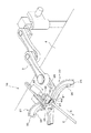
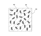
以下、本発明を実施するための最良の形態である内視鏡保持装置10を、添付図面に基づいて具体的に説明する。図1に内視鏡保持装置10の斜視図を示す。内視鏡保持装置10は、第1保持部20と、第2保持部21と、第3保持部22とを備えている。内視鏡の本体部2は、第3保持部22のホルダー53に保持される。ホルダー53と内視鏡の本体部2との間に触覚センサが配置され、内視鏡の本体部に加わる触圧をセンシングする。
Hereinafter, an
内視鏡保持装置10は、多関節のアーム3に取り付けられている。アーム3は、手術台4の側部に一端が固定されており、内視鏡保持装置10を手術台4に対して縦横及び垂直方向に移動させることができる。アーム3と、内視鏡保持装置10の第1保持部20と、第2保持部21と、第3保持部22とは、図示されない制御手段によって指定された移動経路を通って移動し、指定された位置姿勢で停止することができる。
The
内視鏡保持装置10の第1保持部20は、アーム3の先端に枢着ピン24によって回転可能な状態で配置されている。第1保持部20は、アーム3によって略水平に支持された円弧角が略100°の第1円弧板25と、この第1円弧板25の内周部に設けられている第1レール26に案内されて移動を行なう第1スライダ27とから構成されている。ここで第1円弧板25は、アーム3によって略水平に保持された状態で、内視鏡の本体部2の患者の体腔への挿入位置が、その円弧の中心位置となるように移動される。第1スライダ27は、第1円弧板25上を移動することにより、水平面上の円弧を描く左右方向の動きを行なうことができる。
The
内視鏡保持装置10の第2保持部21は、第1保持部20の第1スライダ27の上面に配置されている。第2保持部21は、第1円弧板25に対して垂直となるように第1スライダ27上に固定されている円弧角が略100°の第2円弧板33と、第2円弧板33の内周部に設けられている第2レール35に案内されて上下方向の円弧移動を行なう第2スライダ34とを備えている。第2保持装置は第1スライダ27の移動に伴って移動することができる。第2スライダ34は、第2円弧板33上を移動することにより、第1円弧板25に対して垂直な面上で円弧を描く上下方向の動きを行なうことができる。
The
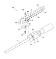
内視鏡保持装置10の第3保持部22の分解斜視図を図2に示す。第3保持部22は、リニアスライダ45とナックル部50とホルダー53とを備えている。リニアスライダ45は、第2スライダ34に突設された一対の保持ピン43が挿通されるガイド孔44を有しており、第2スライダ34に対してスライド可能な状態で保持されている。
An exploded perspective view of the third holding
図2に示すように、リニアスライダ45の底面には直線状ラック46が設けられ、ピニオンギア48が噛合している。リニアスライダ45は、一対の保持ピン43によって第2スライダ34に支持された状態で、図示されない制御手段によってピニオンギア48の回転が制御されることによって、第2保持部21に対して斜め前後方向に移動することができる。尚、ここでいう斜め前とは、水平面に対してリニアスライダ45がなす角度で第2円弧板33の中心方向に向かう方向のことであって、図1の状態の内視鏡保持装置10においては矢印Aで示される方向である。このような斜め前の方向は、通常、手術台4に横臥した状態の患者の体内に内視鏡の本体部2がより深く挿入される方向であり、また斜め後ろの方向とは患者の体内から内視鏡を取り出す方向である。
As shown in FIG. 2, a
リニアスライダ45の前端部には、リニアスライダ45に対して垂直に支持軸49が設けられている。逆コの字状をなすナックル部50が、支持軸49に対して回転可能に支持されている。ナックル部50の開口側の両端部には、支持軸49と垂直となる同一の軸上に上下一対となる雌ねじ孔51が形成されている。ねじ孔51に一対のボールプランジャー52が螺入される。ボールプランジャー52は、その先端のボールで六面体状の外形形状を有するホルダー53を回転可能に支持する。
A
内視鏡の本体部2は、ホルダー53の内側に保持される。ホルダー53の上面と下面の中央部には円錐状の支持穴58が穿設されており、そこにナックル部50に螺合されたボールプランジャー52が挿入されることで、ホルダー53と内視鏡の本体部2は第3保持部22のナックル部50に回転可能な状態で支持される。
The
すなわち、ホルダー53と内視鏡の本体部2は支持軸49とボールプランジャー52を軸としてこの両方の軸に対して回転可能に保持されており、内視鏡の本体部2が斜め前後方向以外の外力を受けたときには、その外力に追従して回転することができる。
That is, the
以上のような構成を有する内視鏡保持装置10は、制御手段によって制御された第1保持部20、第2保持部21及び第3保持部22の各動きを合成した動きが、水平方向の円弧運動(図1における左右方向の円弧運動)、垂直方向の円弧運動(図1における上下方向の円弧運動)及びリニアスライダ45と略平行な直線運動(図1における斜め前後方向の運動)の合成運動として、内視鏡の本体部2に与えられる。内視鏡保持装置10の左右方向、上下方向又は斜め前後方向のいずれかの方向の運動が指定された経路に対してずれを生じていた場合、特に保持された内視鏡の本体部2が斜め前方即ち患者の体内に侵入する方向に移動している際には、内視鏡の本体部2と患者の組織とが強く接触して内視鏡の本体部2に意図されない大きな圧力が加わる場合がある。このとき内視鏡の本体部2に加わる様々な方向からの圧力(即ち触圧)をセンシングするために、本実施の形態においては、内視鏡を保持するホルダー53の内側に触覚センサが配置されている。
The
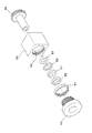
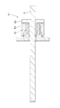
以下に於いては、内視鏡保持装置10の第3保持部22の中で、ナックル部50の先端に配置されて内視鏡の本体部2を直接保持する部分を内視鏡保持部23と称する。内視鏡保持部23は、パイプサポート55と、触覚センサと、センサ特性調整部材60と、ホルダー53とを備えることが好ましい。内視鏡の本体部2を保持した状態の内視鏡保持部23の断面図を図3に示す。又、内視鏡保持部23の分解斜視図を図4に示す。
In the following description, the portion of the third holding
触覚センサとして、1又は2以上の断面が円形に形成された環状のセンサ素子57(以下、Oリング状素子57とも言う)と1又は2以上の断面が四角形に形成された環状のセンサ素子58(以下、角断面リング状素子58とも言う)が互いの側面を接するように配置されて用いられることが好ましい。又、Oリング状素子57と、角断面リング状素子58とは互いの検出感度が異なっていることが好ましい。
As a tactile sensor, an annular sensor element 57 (hereinafter also referred to as an O-ring-like element 57) having one or more cross sections formed in a circle and an
ホルダー53の中心部には円孔54が貫通形成されている。パイプサポート55は、断面がT字状で中心に内視鏡の本体部2を挿通して保持することのできる貫通孔57が形成されている。パイプサポート55の外周には、1又は2以上のOリング状素子57と1又は2以上の角断面リング状素子58とが装着される。パイプサポート55と、1又は2以上のOリング状素子57と1又は2以上の角断面リング状素子58とは、ホルダー53の円孔54の内部に配置される。
A
1又は2以上のOリング状素子57と、1又は2以上の角断面リング状素子58のうち少なくとも一つのセンサ素子が、コイル状炭素繊維がマトリクスとしての樹脂又はゴムに分散されて形成されていることが好ましい。コイル状炭素繊維を用いない他のセンサ素子については、既知の圧電素子を適用することができるが、あらゆる方向の触圧を高感度に検出するためには、少なくとも一つのセンサ素子が、コイル状炭素繊維がマトリクスとしての樹脂又はゴムに分散されて形成されていることが好ましい。
At least one sensor element among one or two or more O-ring-shaped
センサ素子のうちの少なくとも一つを構成するマトリクスの硬さは、JIS A硬度(JIS K6301)で10〜100が好ましい。JIS A硬度で10未満の場合には、マトリクスが軟らかくなり過ぎて、ノイズの検出が大きくなって好ましくない。一方、JIS A硬度が100を越える場合には、マトリクスが硬くなり過ぎて、触圧の伝播性が悪く、検知感度が低下する。マトリクスは誘電体であって静電容量(C)を有し、コンデンサとして作用する。 The hardness of the matrix constituting at least one of the sensor elements is preferably 10 to 100 in terms of JIS A hardness (JIS K6301). If the JIS A hardness is less than 10, the matrix becomes too soft, and noise detection becomes large, which is not preferable. On the other hand, when the JIS A hardness exceeds 100, the matrix becomes too hard, the propagation property of the contact pressure is poor, and the detection sensitivity is lowered. The matrix is a dielectric, has a capacitance (C), and acts as a capacitor.
マトリクスを構成する樹脂としては、シリコーン樹脂、ウレタン樹脂、エポキシ樹脂、スチレンと熱可塑性エラストマーとの共重合樹脂等が用いられる。ゴムとしては、シリコーンゴム、ウレタンゴム等が用いられる。マトリクスの硬さはセンサ素子の感度を向上させる上で重要であり、マトリクスとして弾性力の優れたシリコーン樹脂、シリコーンゴム等を用いた場合には、微小な触圧でも伸縮してその触圧を高感度で検知することができる。一方、硬いシリコーン樹脂、ウレタン樹脂、スチレンと熱可塑性エラストマーとの共重合樹脂等を用いた場合には、大きな触圧でないと伸縮せず、センサ素子の感度は低いが、幅広い触圧範囲を検知することができる。これらの特性を生かして、それぞれのOリング状素子57と角断面リング状素子58を異なるマトリクス樹脂で形成することにより、一層幅広い触圧範囲を検知することができる。
As the resin constituting the matrix, silicone resin, urethane resin, epoxy resin, copolymer resin of styrene and thermoplastic elastomer, or the like is used. As the rubber, silicone rubber, urethane rubber or the like is used. The hardness of the matrix is important for improving the sensitivity of the sensor element. When a silicone resin or silicone rubber with excellent elasticity is used as the matrix, the contact pressure can be expanded and contracted even with a minute contact pressure. It can be detected with high sensitivity. On the other hand, when a hard silicone resin, urethane resin, copolymer resin of styrene and thermoplastic elastomer, etc. are used, it will not expand or contract unless the contact pressure is large, and the sensitivity of the sensor element is low, but a wide contact pressure range is detected. can do. By making use of these characteristics, each of the O-
マトリクスに分散させるコイル状炭素繊維としては、1本の炭素繊維で螺旋構造を形成するものや、2本の炭素繊維で二重螺旋構造を形成するもののうち、一方又は両方を組み合わせて使用することができる。コイル状炭素繊維は、コイルの直径が20nm〜100μmであり、コイルの長さは10nm〜50mmである。コイルの直径が20nm未満のコイル状炭素繊維は、製造が困難である。又、コイルの直径が100μmを超えるコイル状炭素繊維も、同様に製造が困難である。またコイル長さが10nm未満であるとインダクタンス成分としての機能を充分に発揮し難くなる。一方、コイル長さは50mmを超えて形成しても良く、センサの厚みに合わせて適当な長さに裁断すればよい。さらに、コイル状炭素繊維の直径は好ましくは1nm〜10μmである。繊維の直径が1nm未満では、コイル状炭素繊維の製造が困難であり、10μmを超えると、コイルの直径を前記範囲に設定することが困難になるからである。なお繊維は断面が真円のものに限らず、楕円形、矩形、不定形になっていてもよい。また、コイル状炭素繊維は、どのような製法で製造されたものであってもよい。 As the coiled carbon fiber dispersed in the matrix, one of carbon fibers forming a helical structure or two carbon fibers forming a double helical structure may be used in combination of one or both. Can do. The coiled carbon fiber has a coil diameter of 20 nm to 100 μm and a coil length of 10 nm to 50 mm. Coiled carbon fibers having a coil diameter of less than 20 nm are difficult to manufacture. Similarly, coiled carbon fibers having a coil diameter exceeding 100 μm are also difficult to manufacture. Further, when the coil length is less than 10 nm, it becomes difficult to sufficiently exhibit the function as an inductance component. On the other hand, the coil length may be formed to exceed 50 mm, and it may be cut to an appropriate length according to the thickness of the sensor. Furthermore, the diameter of the coiled carbon fiber is preferably 1 nm to 10 μm. This is because if the fiber diameter is less than 1 nm, it is difficult to produce a coiled carbon fiber, and if it exceeds 10 μm, it is difficult to set the coil diameter in the above range. The fiber is not limited to a perfect circle in cross section, and may be oval, rectangular, or indefinite. The coiled carbon fiber may be manufactured by any manufacturing method.
コイル状炭素繊維は伸縮性(弾力性)があり、その伸縮により電気特性であるインダクタンス(L)、静電容量(C)及び電気抵抗(R)が変化するため、それらの変化量に基づいて触圧を検知することができる。一例を挙げると、コイル状炭素繊維を伸ばすとインダクタンス、静電容量及び電気抵抗が増加し、収縮させるとインダクタンス、静電容量及び電気抵抗が減少する場合がある。そして、コイル状炭素繊維を伸長もしくは収縮させた後元の長さに戻すと、インダクタンス、静電容量及び電気抵抗は元の値まで再現性良く戻る。マトリクス中に分散しているコイル状炭素繊維に対してマトリクスの外部から触圧が加わったとき、まずマトリクスが伸縮し、次いでコイル状炭素繊維が伸縮するため、マトリクスを介してコイル状炭素繊維に加わる触圧に基づいてインダクタンス、静電容量及び電気抵抗の値が変化する。 The coiled carbon fiber has stretchability (elasticity), and the expansion and contraction changes the electrical characteristics such as inductance (L), capacitance (C), and electrical resistance (R). Tactile pressure can be detected. For example, when the coiled carbon fiber is stretched, the inductance, capacitance, and electrical resistance may increase, and when contracted, the inductance, capacitance, and electrical resistance may decrease. When the coiled carbon fiber is stretched or contracted and then returned to its original length, the inductance, capacitance, and electrical resistance return to their original values with good reproducibility. When contact pressure is applied to the coiled carbon fiber dispersed in the matrix from the outside of the matrix, the matrix first expands and contracts, and then the coiled carbon fiber expands and contracts. The values of inductance, capacitance, and electric resistance change based on the applied contact pressure.
マトリクスにコイル状炭素繊維を分散させる方法としては、マトリクス前駆体としてのシリコーン樹脂にコイル状炭素繊維を添加し、撹拌して均一に分散させた後、脱泡し、鋳型に充填して成形する方法や、ポリスチレンや熱可塑性エラストマーのペレットを加熱溶融し、それにコイル状炭素繊維を添加し、撹拌して均一に分散させた後、鋳型に流し込み、加圧成形する方法などがある。 As a method of dispersing the coiled carbon fiber in the matrix, the coiled carbon fiber is added to the silicone resin as the matrix precursor, and the mixture is stirred and dispersed uniformly, then defoamed, filled in a mold and molded. And a method of heating and melting pellets of polystyrene or thermoplastic elastomer, adding a coiled carbon fiber thereto, stirring and dispersing uniformly, then pouring into a mold, and pressure molding.
マトリクスが誘電体により形成されて静電容量成分を有するものであるときには、各センサ素子の相互間に存在するマトリクスはコンデンサとして作用する。そして、コイル状炭素繊維が周囲のマトリクスを介して互いに接続されることにより、複合共振回路である電気的等価回路として構成されて、センサ素子全部が一つのLCR共振回路として作用することができる。 When the matrix is formed of a dielectric and has a capacitance component, the matrix existing between the sensor elements acts as a capacitor. Then, the coiled carbon fibers are connected to each other via a surrounding matrix, so that the sensor element is configured as an electrically equivalent circuit which is a composite resonance circuit, and all the sensor elements can act as one LCR resonance circuit.
1又は2以上のOリング状素子57と1又は2以上の角断面リング状素子58とで構成される触覚センサには、図示されない1対の電極が接続されている。電極は、図示されないセンサ本体部と接続されている。触覚センサに加わる触圧の微小な変化により、触覚センサのインダクタンス、静電容量及び電気抵抗が変化し、その変化によりセンサ出力信号が変化する。センサ出力信号の変化は、電極を介してセンサ本体部に入力される。センサ本体部は、基準信号を発振する発振回路と、検知手段及び信号調整手段としての移相部と、検知手段としての検波部とを備えており、センサ出力信号の変化は、検波部における直交検波により検知され、インダクタンス、静電容量及び電気抵抗の変化傾向や変化量が求められる。Oリング状素子57と角断面リング状素子58のうちの少なくとも1つがコイル状炭素繊維を含むことにより、いずれの方向から受けた微小な圧力をも高感度に検知可能に構成することができる。
A tactile sensor composed of one or two or more O-
1又は2以上のOリング状素子57と1又は2以上の角断面リング状素子58のうち、2以上のセンサ素子について、コイル状炭素繊維がマトリクスとしての樹脂又はゴムに分散されて形成されている場合には、マトリクスの種類若しくは硬度、又はコイル状炭素繊維の種類若しくは含有量を調整することで、センサ素子としての検出感度が互いに異なるように構成することが好ましい。これにより、触覚センサ全体としてより広い圧力範囲の触圧を検出することが可能となる。
Of two or more sensor elements out of one or two or more O-
ホルダー53の一端部の内側にはネジ山が設けられており、センサ特性調整部材60と調節ネジ固定用ナット61とを、ホルダー53のこのネジ山に螺合させることで、触覚センサに接するように配置されたセンサ圧縮板62を触覚センサ側に加圧することができる。加圧されたセンサ圧縮板62は、装着された全てのOリング状素子57と角断面リング状素子58に圧縮力を加える。ここで加えられる圧縮力は、ホルダー53に対するセンサ特性調整部材60の位置を調整することによって、精度高く調整することができる。
A screw thread is provided inside one end of the
センサ特性調整部材60,調節ネジ固定用ナット61,及びセンサ圧縮板62は、共にポリエチレン、ポリプロピレン、ポリスチレン、ポリ酢酸ビニル、ABS樹脂、アクリル樹脂などの汎用プラスチックの他、ポリアミド、ポリアセタール、ポリカーボネート、ポリエチレンテレフタレート、環状ポリオレフィンなどのエンジニアプラスチックから成形することができ、特にネジ部などの耐性を考慮してポリアセタールなどのエンジニアプラスチックが好ましい。
The sensor
センサ特性調整部材60は図3に示すような螺合によって接続する場合、接続部分に使用されるネジ部の長さは5〜10mm程度であることが好ましい。この長さが短すぎると簡単に外れたり、斜めに螺合されるなどの不都合があり、一方長すぎると固定するまでに何回転も必要となって操作性に劣るからである。またセンサ圧縮板62の厚さは1〜5mm程度であることが好ましい。厚みが薄すぎると取扱に不便なだけでなく容易に変形して触覚センサに均一な圧力を作用させることが困難になり、厚みが厚すぎるとセンサ調整部材を接続するためにネジ部の長さを確保するのが難しくなるからである。
When the sensor
ホルダー53に対するセンサ特性調整部材60の位置を調整し、装着されている全てのOリング状素子57と角断面リング状素子58に圧縮力を加えることで、センサの感度が高い領域・範囲でセンシングするための調整を容易且つ高精度に行うことができる。すなわち、検知感度・検知幅・検知速度・定量性等の初期特性に潜在的なばらつきがあるOリング状素子57と角断面リング状素子58に対して、これらをホルダー53内に配置する際にセンサ特性調整部材60によって圧縮力を加えることで、これらのセンサ素子の特性のばらつきの調整を行うことが可能となる。
Sensing is performed in a region / range where the sensitivity of the sensor is high by adjusting the position of the sensor
触覚センサが、1又は2以上のOリング状素子57と1又は2以上の角断面リング状素子58とで構成されている場合には、ホルダー53内の円孔54内には図3に示すように互いのセンサ素子との間に部分的に隙間が形成される。このためセンサ素子が隙間なく装着されている場合と比較すると、センサ特性調整部材60によって圧縮された場合に、より圧縮が容易となっている。このため、本実施形態の触覚センサは、所望の検出感度となるような調整を非常に容易に行うことができる。
When the tactile sensor is composed of one or two or more O-
複数のOリング状素子57と角断面リング状素子58の検出感度が互いに異なるように構成されることにより、触覚センサとしてより広い圧力範囲で触圧をセンシングすることが可能となる。その結果、わずかな触圧の変化を見逃すことがなく、内視鏡が内臓諸器官に対して損傷を及ぼすような接触を引き起こす前に、内視鏡の動きを制御することができる。
By configuring the plurality of O-
以下、実施例1〜3及び比較例により、前記実施形態をさらに具体的に説明する。 Hereinafter, the embodiment will be described more specifically with reference to Examples 1 to 3 and a comparative example.
(実施例1)本実施例の内視鏡保持装置10の触覚センサには、2個のOリング状素子57と1個の角断面リング状素子58とが用いられている。Oリング状素子57と角断面リング状素子58とは、図3に示すように、内視鏡保持部23のパイプサポート55の外周に交互に装着されて、ホルダー53の円孔54の内部に配置されている。
(Embodiment 1) For the tactile sensor of the
本実施例で用いられる2個のOリング状素子57は、同一の構成で同一寸法に形成されている。すなわちOリング状素子57は、マトリクスとしてシリコーン樹脂の一種である二液型RTVゴム(商品名:KE103;信越化学工業製)の中に5.0重量%のコイル状炭素繊維が分散されて構成されている。コイル状炭素繊維としては、コイルの長さが90μm以下、コイルの直径が平均5μm程度のものが使用されている。そしてOリング状素子57は、内径が14mm、外径が18mmであって、その断面が直径が2mmの円形となるように形成されている。
The two O-
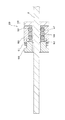
本実施例で用いられる1個の角断面リング状素子58の断面図を図5に示す。角断面リング状素子はリングの内径が14mmであって、その断面が一辺2mmの正方形に形成されている。角断面リング状素子58は、Oリング状素子57と同様に、マトリクス65としての二液型RTVゴムの中に5.0重量%のコイル状炭素繊維66が分散されて構成されている。コイル状炭素繊維66は、コイルの長さが90μm以下、コイルの直径が平均5μm程度のものが使用されている。尚、図5に示すコイル状炭素繊維65は、その分散状態と形状の理解を容易にするために、その大きさを誇張して描かれている。
FIG. 5 shows a cross-sectional view of one square cross-section ring-shaped
触覚センサの検出感度と検出範囲とを測定するために、内視鏡保持部23に保持されている内視鏡の本体部2の先端に荷重をかけて、触覚センサの出力電圧を測定した。本実施例の触覚センサは、センサ特性調整部材60によって圧縮前の素子体積に対する圧縮後の素子体積の比率が0.9となるように予め圧縮されている。又、内視鏡の本体部2は、内視鏡保持部23のボールプランジャー52で定義される回転軸から内視鏡の先端までの距離が200mmとなるように保持されている。
In order to measure the detection sensitivity and the detection range of the tactile sensor, a load was applied to the tip of the
上記の如く保持された内視鏡の本体部2の先端に、100gfの上向きの荷重をかけた場合に、触覚センサの出力電圧は3.3Vであった。又、触覚センサの出力電圧で表される検出範囲は、0〜20.0Vであった。尚、本実施例における検出範囲の最大値は、触覚センサが接続されているセンサ本体部における信号処理回路の出力電圧範囲の上限値に相当する値であり、信号処理回路の構成を変更してその出力電圧範囲を広くすることによって、20.0Vよりも広い範囲の検出が可能となる。
When an upward load of 100 gf was applied to the distal end of the endoscope
(実施例2)本実施例における内視鏡保持装置の触覚センサには、3個の角断面リング状素子が用いられている。このうちの2個は、実施例1の角断面リング状素子58と同一の構成を有している。残る1個の角断面リング状素子は、外形形状は他の角断面リング状素子と同一であるが、その組成が異なっている。即ちこの角断面リング状素子は、マトリクスとしての二液型RTVゴムの中に10.0重量%のコイル状炭素繊維が分散されて構成されている。コイル状炭素繊維の含有量が10.0重量%となっていることによって、この角断面リング状素子は、他の角断面リング状素子と比較して、検出感度が高くなっている。3個の角断面リング状素子は、内視鏡保持部23のパイプサポート55の外周に互いの側面が接するように装着されて、ホルダー53の円孔54の内部に配置されている。触覚センサ以外の内視鏡保持装置の構成については実施例1と同一であり、重複説明を割愛する。
(Embodiment 2) Three angular section ring-shaped elements are used for the tactile sensor of the endoscope holding apparatus in the present embodiment. Two of them have the same configuration as the angular section ring-shaped
本実施例では、実施例1と同様の圧縮比率となるようにセンサ特性調整部材60によって触覚センサを圧縮した状態で、触覚センサの検出感度と検出範囲とを測定している。内視鏡の本体部2の先端に100gfの上向きの荷重をかけた場合の触覚センサの出力電圧は2.4Vであった。又、触覚センサの出力電圧で表される検出範囲は、0〜14.0Vであった。
In the present embodiment, the detection sensitivity and the detection range of the tactile sensor are measured in a state where the tactile sensor is compressed by the sensor
(実施例3)本実施例における内視鏡保持装置の触覚センサには、3個のOリング状素子57が用いられている。Oリング状素子57は、内視鏡保持部23のパイプサポート55の外周に互いの側面が接するように装着されて、ホルダー53の円孔54の内部に配置されている。本実施例では、実施例1と同様の圧縮比率で触覚センサの検出感度と検出範囲とを測定している。内視鏡の本体部2の先端に100gfの上向きの荷重をかけた場合の触覚センサの出力電圧は3.1Vであった。又、触覚センサの出力電圧で表される検出範囲は、0〜20.0Vであった。尚、本実施例における検出範囲の最大値は、触覚センサが接続されているセンサ本体部における信号処理回路の出力電圧範囲の上限値に相当する値であり、信号処理回路の構成を変更してその出力電圧範囲を広くすることによって、20.0Vよりも広い範囲の検出が可能となる。
(Embodiment 3) Three O-
(比較例)比較例の内視鏡保持装置の内視鏡保持部71の構成を、図6に示す。比較例の触覚センサは、パイプサポート55の外周に配置された1個の円筒状のセンサ素子70で構成されている。このセンサ素子70は内径14mm、外径18mm、長さ6mmの円筒形のセンサ素子であって、マトリクスとしての二液型RTVゴム(商品名:KE103;信越化学工業製)の中にコイル状炭素繊維を5.0重量%添加して形成されている。添加されているコイル状炭素繊維のコイルの長さは90μm以下であって、コイルの直径は平均5μm程度である。
(Comparative Example) FIG. 6 shows the configuration of the
比較例の触覚センサを構成するセンサ素子70の検出感度と検出範囲との測定を行った。最初に、センサ特性調整部材60によるセンサ素子70の圧縮を行わない状態で測定を行った。内視鏡の本体部2の先端に100gfの上向きの荷重をかけた場合の触覚センサの出力電圧は1.3Vであった。又、触覚センサの出力電圧で表される検出範囲は、0〜7.4Vであった。次に、センサ特性調整部材60によってセンサ素子70を、圧縮前の素子体積に対する圧縮後の素子体積の比率が0.9となるように圧縮して、検出感度と検出範囲とを測定した。内視鏡の本体部2の先端に100gfの上向きの荷重をかけた場合の触覚センサの出力電圧は1.8Vであった。又、触覚センサの出力電圧で表される検出範囲は、0〜10.2Vであった。
The detection sensitivity and the detection range of the
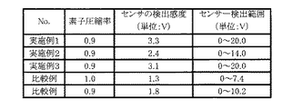
実施例1〜3と比較例に示した内視鏡保持装置のセンサ素子の検出感度と検出範囲とを図7に示す。尚、図中の圧縮率とは、センサ特性調整部材60によって触覚センサを圧縮する前の体積を基準として圧縮後の体積の比率を求めた値であり、触覚センサが全く圧縮されていない場合にその値は1.0となっている。それぞれの実施例と比較例の検出感度と検出範囲の測定結果から明らかであるように、触覚センサがOリング状素子と角断面リング状素子とで構成されている実施例1の場合には、同一の荷重に対するセンサの出力電圧が最も高くなり、従って微小な荷重でも検出が可能で高い検出感度を有すると同時に、センサの検出範囲が最も広くなっている。又、触覚センサが複数の角断面リング状素子で構成されている実施例2の場合には、その中の1つの角断面リング状素子のコイル状炭素繊維の添加量を増加させたことにより、比較例よりも高い検出感度を有すると同時に、センサの検出範囲が広くなっている。更に、複数のOリング状素子で触覚センサを構成した実施例3の場合、実施例1と比較して検出感度はやや低くなるものの、非常に広い検出範囲を得ることが可能となっている。
FIG. 7 shows the detection sensitivity and detection range of the sensor elements of the endoscope holding apparatuses shown in Examples 1 to 3 and the comparative example. The compression rate in the figure is a value obtained by calculating the ratio of the volume after compression with reference to the volume before the tactile sensor is compressed by the sensor
以上、発明を実施するための最良の形態と実施例に基づいて、本発明に係る内視鏡保持装置の具体例を詳細に説明したが、これらは例示に過ぎず、特許請求の範囲を限定するものではない。特許請求の範囲に記載の技術には、以上に例示した具体例を様々に変形、変更したものが含まれる。例えば、実施例1〜3の触覚センサは、マトリクスとしての樹脂にコイル状炭素繊維を5.0重量%又は10.0%添加して形成されているが、コイル状炭素繊維の添加量を適切に調整してより検出感度を向上させることが可能である。 As described above, specific examples of the endoscope holding device according to the present invention have been described in detail based on the best modes and examples for carrying out the invention. However, these are merely examples, and the scope of the claims is limited. Not what you want. The technology described in the claims includes various modifications and changes of the specific examples illustrated above. For example, the tactile sensors of Examples 1 to 3 are formed by adding 5.0% by weight or 10.0% of a coiled carbon fiber to a resin as a matrix. It is possible to further improve the detection sensitivity by adjusting.
また例えば、触覚センサは、内視鏡とパイプサポートとの間に装着することも、あるいは他の部分、例えばボールプランジャー52によるホルダー53の支持部や、ナックル部50の支持部に装着することもできる。さらに触覚センサを複数箇所に設けて検知感度を高めることもできる。
Further, for example, the tactile sensor may be mounted between the endoscope and the pipe support, or may be mounted on another part, for example, the support part of the
本発明に係る内視鏡保持装置の特に触覚センサの構成は、工業用ロボットアーム、内視鏡以外の医療機器、その他工業用制御機器やヒューマノイドロボット等の分野で、圧力をセンシングしてその動作を制御する必要のある各種機器に適用が可能である。 The configuration of the tactile sensor of the endoscope holding apparatus according to the present invention is particularly sensitive to pressure sensing in the fields of industrial robot arms, medical equipment other than endoscopes, other industrial control equipment, and humanoid robots. It can be applied to various devices that need to control the above.
2 内視鏡の本体部
3 アーム
4 手術台
10 内視鏡保持装置
20 第1保持部
21 第2保持部
22 第3保持部
23,71 内視鏡保持部
24 枢着ピン
25 第1円弧板
26 第1レール
27 第1スライダ
33 第2円弧板
34 第2スライダ
35 第2レール
43 保持ピン
44 ガイド孔
45 リニアスライダ
46 直線状ラック
48 ピニオンギア
49 支持軸
50 ナックル部
52 ボールプランジャー
53 ホルダー
54 円孔
57 断面が円形に形成された環状のセンサ素子(Oリング状素子)
58 断面が四角形に形成された環状のセンサ素子(角断面リング状素子)
60 センサ特性調整部材
61 調節ネジ固定用ナット
62 センサ圧縮板
65 マトリクス
66 コイル状炭素繊維
70 センサ素子
DESCRIPTION OF
58 Annular sensor element with a square cross-section (ring-shaped element with a square cross section)
60 sensor
Claims (4)
前記ホルダーの内側に装着されており、内視鏡に加わる触圧をセンシングする触覚センサと、
前記ホルダーのネジ山に螺合されて、触覚センサを圧縮してセンサ感度を調整することのできるセンサ特性調整部材とを備えており、
前記触覚センサが、複数のセンサ素子を含むことを特徴とする内視鏡保持装置。 A holder in which a circular hole for holding the endoscope is formed, and a thread is provided at one end;
A tactile sensor that is attached to the inside of the holder and senses a contact pressure applied to the endoscope;
A sensor characteristic adjusting member that is screwed into the thread of the holder and compresses the tactile sensor to adjust the sensor sensitivity;
The endoscope holding apparatus, wherein the tactile sensor includes a plurality of sensor elements.
Priority Applications (1)
| Application Number | Priority Date | Filing Date | Title |
|---|---|---|---|
| JP2008325981A JP2010142575A (en) | 2008-12-22 | 2008-12-22 | Endoscope holding device |
Applications Claiming Priority (1)
| Application Number | Priority Date | Filing Date | Title |
|---|---|---|---|
| JP2008325981A JP2010142575A (en) | 2008-12-22 | 2008-12-22 | Endoscope holding device |
Publications (1)
| Publication Number | Publication Date |
|---|---|
| JP2010142575A true JP2010142575A (en) | 2010-07-01 |
Family
ID=42563604
Family Applications (1)
| Application Number | Title | Priority Date | Filing Date |
|---|---|---|---|
| JP2008325981A Pending JP2010142575A (en) | 2008-12-22 | 2008-12-22 | Endoscope holding device |
Country Status (1)
| Country | Link |
|---|---|
| JP (1) | JP2010142575A (en) |
Cited By (4)
| Publication number | Priority date | Publication date | Assignee | Title |
|---|---|---|---|---|
| WO2017169143A1 (en) * | 2016-03-30 | 2017-10-05 | ソニー株式会社 | Information processing device, information processing method, and calibration system |
| CN113784682A (en) * | 2019-03-07 | 2021-12-10 | 普罗赛普特生物机器人公司 | Robotic arm and method for tissue ablation and imaging |
| US12178537B2 (en) | 2020-06-26 | 2024-12-31 | Procept Biorobotics Corporation | Systems for defining and modifying range of motion of probe used in patient treatment |
| US12419701B2 (en) | 2019-11-11 | 2025-09-23 | Procept Biorobotics Corporation | Surgical probes for tissue resection with robotic arms |
-
2008
- 2008-12-22 JP JP2008325981A patent/JP2010142575A/en active Pending
Cited By (8)
| Publication number | Priority date | Publication date | Assignee | Title |
|---|---|---|---|---|
| WO2017169143A1 (en) * | 2016-03-30 | 2017-10-05 | ソニー株式会社 | Information processing device, information processing method, and calibration system |
| CN113784682A (en) * | 2019-03-07 | 2021-12-10 | 普罗赛普特生物机器人公司 | Robotic arm and method for tissue ablation and imaging |
| JP2022533297A (en) * | 2019-03-07 | 2022-07-22 | プロセプト バイオロボティクス コーポレイション | Robotic arm and method for tissue ablation and imaging |
| US12089907B2 (en) | 2019-03-07 | 2024-09-17 | Procept Biorobotics Corporation | Robotic arms and methods for tissue resection and imaging |
| CN113784682B (en) * | 2019-03-07 | 2024-09-20 | 普罗赛普特生物机器人公司 | Robotic arms and methods for tissue resection and imaging |
| JP7607574B2 (en) | 2019-03-07 | 2024-12-27 | プロセプト バイオロボティクス コーポレイション | Robotic arms and methods for tissue ablation and imaging - Patents.com |
| US12419701B2 (en) | 2019-11-11 | 2025-09-23 | Procept Biorobotics Corporation | Surgical probes for tissue resection with robotic arms |
| US12178537B2 (en) | 2020-06-26 | 2024-12-31 | Procept Biorobotics Corporation | Systems for defining and modifying range of motion of probe used in patient treatment |
Similar Documents
| Publication | Publication Date | Title |
|---|---|---|
| CN113038900B (en) | Surgical instrument with sensor alignment cable guide | |
| JP5936914B2 (en) | Operation input device and manipulator system including the same | |
| JP6634504B2 (en) | Endoscopic surgery device | |
| JP2015036161A (en) | Joint mechanism | |
| CA2908845C (en) | Ear clip for medical monitoring device | |
| JP2010142575A (en) | Endoscope holding device | |
| US20210267709A1 (en) | Force sensing device, medical endodevice and process of using such endodevice | |
| Chen et al. | Two-axis bend sensor design, kinematics and control for a continuum robotic endoscope | |
| JP2008017903A (en) | Endoscope holding device | |
| JPWO2005012829A1 (en) | Angle measuring instrument | |
| Vajpeyi et al. | A novel, flexible, full-length, pressure-sensing sleeve for colonoscopes | |
| CN115813317A (en) | Endoscope with a detachable handle | |
| AU2017202575B2 (en) | Devices, systems, and methods for locating pressure sensitive critical structures | |
| JP2009226011A (en) | Endoscope holding device | |
| Faragasso et al. | Disposable stiffness sensor for endoscopic examination | |
| US10674893B2 (en) | Endoscopic surgical device and guide device | |
| Othman | Systems and Methods for Restoring Tactile Sensation in Laparoscopic Surgery | |
| US10448810B2 (en) | Surgical apparatus for endoscope and outer tube | |
| US20190125242A1 (en) | Surgical tool with pressure sensor | |
| Chen | Design of Pressure Feedback Sensors for Miniaturized Intra-ventricular Neurosurgery Robotic Tools | |
| Usman et al. | Sensorized laparoscopic surgical grasper with integrated capacitive force sensor for robot-assisted minimally invasive surgery | |
| WO2016157470A1 (en) | Touch sensor, medical device, and medical system | |
| CN115300007A (en) | A universal control part of an electric multi-degree-of-freedom flexible instrument | |
| CN115462906A (en) | End Devices and Surgical Instruments | |
| TWM505909U (en) | Housing of endoscope display device |