JP2010142017A - Pole incorporating cable - Google Patents
Pole incorporating cable Download PDFInfo
- Publication number
- JP2010142017A JP2010142017A JP2008315731A JP2008315731A JP2010142017A JP 2010142017 A JP2010142017 A JP 2010142017A JP 2008315731 A JP2008315731 A JP 2008315731A JP 2008315731 A JP2008315731 A JP 2008315731A JP 2010142017 A JP2010142017 A JP 2010142017A
- Authority
- JP
- Japan
- Prior art keywords
- cable
- column
- electric device
- attached
- electric
- Prior art date
- Legal status (The legal status is an assumption and is not a legal conclusion. Google has not performed a legal analysis and makes no representation as to the accuracy of the status listed.)
- Granted
Links
Images
Landscapes
- Suspension Of Electric Lines Or Cables (AREA)
Abstract
【課題】 支柱に取付けられる機器類への配線作業を、短時間でかつ容易にできるようにする。
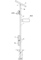
【解決手段】 街路に建柱され、カメラ2a、照明機器2b、制御装置3、蓄電池ボックス3a、太陽電池パネル5を取付け可能とした支柱1の内部に、そのカメラ2a、照明機器2bを動作させるためのケーブル10を、前記支柱1の建柱前に配線するようにした。建柱前に予め必要なケーブル10が配線されていれば、建柱後の支柱1内にケーブル10を引き入れて取り回す作業を省略できるので、作業は、各機器2の端子と制御装置3の端子にそれぞれ対応するケーブル10の端子14を接続するのみとなる。このため、配線作業は短時間でかつ容易にできる。また、その配線したケーブル10を、支柱1のケーブル挿通孔12,13にブッシュ12a,13aを介して挿通すれば、ケーブル10は表面が損傷することなく、張力止め15を用いればしっかりと固定される。
【選択図】図1PROBLEM TO BE SOLVED: To easily perform wiring work to equipment attached to a column in a short time.
SOLUTION: A camera 2a and a lighting device 2b are operated inside a column 1 which is built on a street and can be attached with a camera 2a, a lighting device 2b, a control device 3, a storage battery box 3a and a solar cell panel 5. For this purpose, the cable 10 is wired in front of the pillar of the column 1. If the necessary cable 10 is wired in advance before the building pillar, the work of drawing the cable 10 into the post 1 after the building pillar and routing it can be omitted. Only the terminal 14 of the cable 10 corresponding to each terminal is connected. For this reason, wiring work can be performed in a short time and easily. Further, if the wired cable 10 is inserted into the cable insertion holes 12 and 13 of the support column 1 through the bushes 12a and 13a, the surface of the cable 10 is not damaged, and the tension stopper 15 is used to fix the cable 10 firmly. The
[Selection] Figure 1
Description
この発明は、照明機器等の各種電気機器類を取付け可能な支柱に関するものである。 The present invention relates to a support column to which various electric devices such as lighting devices can be attached.
近年、街路に設置される照明用等の支柱に、照明機器のほか、各種電気機器、例えば、カメラ、センサ、非常通報装置等が取付けられる機会が増えている。また、それ以外にも各種表示灯、広告灯等の電気機器が取付けられる場合もある。さらに、それらを動作させる電源を確保するため、ソーラ発電装置などの電源装置が取付けられる場合もある。 In recent years, in addition to lighting devices, various electric devices such as cameras, sensors, emergency call devices, and the like have been increasingly attached to lighting columns installed on streets. In addition, electric devices such as various indicator lights and advertisement lights may be attached. Furthermore, in order to secure a power source for operating them, a power source device such as a solar power generator may be attached.
これらの電気機器を支柱に取付ける際の手順を、中空の鋼管支柱を用いた本発明の実施形態の説明図である図1に基づいて説明すると、前記支柱の所定箇所に各機器類、及びその機器類を動作させるのに必要な制御盤等を固定するとともに、支柱の内部に必要なケーブルを配線し固定する。そして、前記制御盤等に電源を接続するとともに、各機器類の端子と制御盤の端子にそれぞれ対応するケーブルの端子を結線する手順で行われる。 The procedure for attaching these electric devices to the column will be described with reference to FIG. 1 which is an explanatory view of an embodiment of the present invention using a hollow steel tube column. In addition to fixing the control panel, etc. necessary to operate the equipment, the necessary cables are wired and fixed inside the column. And while connecting a power supply to the said control board etc., it carries out in the procedure of connecting the terminal of the cable corresponding to the terminal of each apparatus, and the terminal of a control board, respectively.
なお、中空の鋼管支柱の内部にケーブルを配線する手法として、例えば、特許文献1に記載のものがある。
In addition, as a method of wiring a cable inside a hollow steel pipe column, for example, there is a method described in
しかし、上記のケーブル配線作業は、既に建てられた支柱に施工しなければならないため、概ね高所での作業となる。また、高所作業となれば、作業者を持ち上げる作業重機等が必要になる場合もある。このため、作業は、大がかりなものとなる。 However, the above-described cable wiring work has to be performed on a column that has already been built, and thus is generally a work at a high place. In addition, when working at a high place, there may be a need for a heavy work machine or the like for lifting an operator. For this reason, work becomes a large-scale thing.
その高所において、支柱内にケーブルを引き入れて取り回す作業は、例えば、高さの異なる2箇所(具体的には、電気機器を取付ける場所に近い部分に設けたケーブル挿通孔と、その電気機器の動作に必要な装置を取付ける場所に近い部分に設けたケーブル挿通孔の2箇所)間で、上下両側からケーブルを引きながらの作業となることもある。このため、作業能率が悪く時間を要することとなるとともに、作業が煩雑である。
したがって、作業時間の短縮、作業の容易化が望まれる。
At the high place, the work of drawing the cable into the support column includes, for example, two places with different heights (specifically, the cable insertion hole provided in the portion close to the place where the electric equipment is installed, and the electric equipment There are cases where the work is performed while pulling the cable from both the upper and lower sides between the two portions of the cable insertion hole provided near the place where the device required for the operation is installed. For this reason, work efficiency is poor and time is required, and the work is complicated.
Accordingly, it is desired to shorten the work time and facilitate the work.
そこで、この発明は、支柱に取付けられる電気機器類への配線作業を、短時間でかつ容易にできるようにすることを課題とする。 Accordingly, an object of the present invention is to make it possible to perform wiring work to electric devices attached to a support in a short time and easily.
上記の課題を解決するために、この発明は、建柱前の支柱内に、予め必要なケーブルを配線したのである。 In order to solve the above-described problems, the present invention wires a necessary cable in advance in a column in front of a building pillar.
建柱前の支柱内に予め必要なケーブルが配線されていれば、建柱後の支柱内にケーブルを引き入れて取り回す作業を省略できるので、作業は、各機器類の端子と制御盤の端子にそれぞれ対応するケーブルの端子を結線するのみとなる。このため、配線作業は短時間でかつ容易にできるようになる。
なお、その配線作業は、支柱の出荷前に工場内で施工してもよいし、建柱作業前に現場で施工した後に建柱するようにしても良い。
If the necessary cables are routed in advance in the pillars before the building pillars, the work of drawing the cables into the pillars after the pillars and routing them can be omitted. Only the corresponding cable terminals are connected. For this reason, the wiring work can be easily performed in a short time.
In addition, the wiring work may be performed in the factory before the support is shipped, or may be performed after the construction work at the site before the construction work.
この発明は、建柱前の支柱内に、予め必要なケーブルを配線したので、その支柱に取付けられる機器類の配線作業を、短時間でかつ容易にできるようになる。 In the present invention, since necessary cables are wired in advance in the columns in front of the building columns, the wiring work of the devices attached to the columns can be easily performed in a short time.
具体的な実施形態としては、街路に建柱される支柱に、電気機器を取付け可能とするとともに、その電気機器の動作に必要な装置を取付け可能とし、前記電気機器及び前記装置を前記支柱の建柱後に取付ける支柱において、前記支柱の内部に、前記電気機器及び前記装置の相互間を結ぶことによりその電気機器を動作させるケーブルを、前記支柱の建柱前に配線したことを特徴とするケーブル内蔵型支柱としたものである。 As a specific embodiment, it is possible to attach an electric device to a pillar that is built on a street, and to attach an apparatus necessary for the operation of the electric device, and to attach the electric device and the device to the pillar. A cable installed after a building pillar, wherein a cable for operating the electrical equipment by connecting the electrical equipment and the device to each other inside the pillar is wired before the construction pillar of the pillar. It is a built-in column.
建柱前の支柱の内部に、電気機器とその電気機器の動作に必要な装置とを結ぶケーブルが配線されているので、建柱後の配線作業は、その電気機器の端子と必要な装置の端子にそれぞれ対応するケーブルの端子を結線するのみでよい。このため、ケーブルの配線作業は、短時間でかつ容易にできるようになる。 Since the cable connecting the electrical equipment and the equipment necessary for the operation of the electrical equipment is wired inside the pillar in front of the construction pillar, the wiring work after the construction pillar is performed by connecting the terminals of the electrical equipment and the necessary equipment. It is only necessary to connect the cable terminals corresponding to the terminals. For this reason, the cable wiring work can be easily performed in a short time.
なお、前記電気機器の動作に必要な装置としては、その電気機器の動作を制御する制御装置及びその電気機器に電気を供給するための電源装置又はそのいずれかとすることができる。すなわち、電気機器と制御装置、電気機器と電源装置、電気機器と制御装置と電源装置とを備えた構成が考えられる。電気機器と制御装置と電源装置とを備える場合、電気機器と制御装置、電気機器と電源装置、制御装置と電源装置のそれぞれを結ぶケーブルを配線することができる。
また、一つの電気機器に対して対応する制御装置が複数備えられている構成、あるいは、対応する電源装置が複数備えられている構成も考えられる。
In addition, as an apparatus required for operation | movement of the said electric equipment, it can be set as the control apparatus which controls the operation | movement of the electric equipment, the power supply device for supplying electricity to the electric equipment, or either. That is, a configuration including an electric device and a control device, an electric device and a power supply device, and an electric device, a control device, and a power supply device can be considered. When the electric device, the control device, and the power supply device are provided, cables connecting the electric device and the control device, the electric device and the power supply device, and the control device and the power supply device can be wired.
Moreover, the structure provided with two or more corresponding control apparatuses with respect to one electric equipment, or the structure provided with two or more corresponding power supply devices is also considered.
前記の構成において、前記支柱の前記電気機器と前記電気機器の動作に必要な装置の取付け場所に臨む箇所に、それぞれケーブル挿通孔が形成されており、前記配線されたケーブルは、その両端が前記各ケーブル挿通孔にブッシュを介して挿通された状態で前記支柱に固定されているようにした構成を採用し得る。
このようにすれば、配線したケーブルは、ブッシュを介してケーブル挿通孔に挿通されてケーブル表面の損傷を保護し、しっかりと支柱に固定されるようになる。
なお、そのブッシュは、ケーブルとともに前記挿通孔に取付けられた後は、支柱内部に雨水や異物等の侵入を阻止し得るものであることが望ましく、また、その挿通孔に嵌め込み容易であるものが望ましい。
In the above-described configuration, cable insertion holes are respectively formed at locations facing the mounting position of the electrical equipment and the device necessary for the operation of the electrical equipment of the support column, and both ends of the wired cable are the above-described ends. A configuration may be adopted in which each cable insertion hole is fixed to the support column while being inserted through a bush.
In this way, the wired cable is inserted into the cable insertion hole via the bush to protect the cable surface from damage, and is firmly fixed to the support column.
In addition, after the bush is attached to the insertion hole together with the cable, it is desirable that the bush can prevent rain water, foreign matter and the like from entering the column, and the bush can be easily fitted into the insertion hole. desirable.
さらに、前記各ケーブル挿通孔に挿通されたケーブルは、その両端に、それぞれケーブルの接続先を理解できる表示を付したタグが外部から視認可能に取付けられているようにした構成を採用し得る。このようにすれば、電気機器の端子と装置の端子にそれぞれ対応するケーブルの端子を結線する際に、ケーブルの誤結線を防止し得る。 Furthermore, the cable inserted into each cable insertion hole may employ a configuration in which a tag with an indication that can understand the connection destination of the cable is attached to both ends so as to be visible from the outside. If it does in this way, when connecting the terminal of the cable respectively corresponding to the terminal of an electric equipment, and the terminal of an apparatus, the incorrect connection of a cable can be prevented.
また、その支柱に、ケーブルを保持することにより、その支柱内におけるケーブルの取り回し状態を維持する機能を有する張力止めを設けることができる。この張力止めは、ケーブルのいずれの部分を保持するものであってもよいが、ケーブルの端部を保持できる位置に設けることが望ましい。ケーブルの端部が支柱の外部に出ている時は、その支柱外の部分に設けることができる。 Moreover, the tension | tensile_strength stop which has the function to maintain the routing state of the cable in the support | pillar by hold | maintaining a cable to the support | pillar can be provided. This tension stopper may hold any part of the cable, but is preferably provided at a position where the end of the cable can be held. When the end of the cable is outside the column, it can be provided outside the column.
なお、街路に建柱され、電気機器及びその電気機器の動作に必要な装置を取付け可能とした支柱の内部に、前記電気機器と前記装置とを結ぶことにより前記電気機器を動作させるケーブルを配線する支柱へのケーブル配線方法として、以下の構成を採用することができる。
すなわち、前記支柱の内部に、前記電気機器と前記装置の相互間を結んでその電気機器を動作させるケーブルを前記支柱の建柱前に配線し、その支柱を建柱した後、その支柱に前記電気機器と前記装置を取付けるとともに、その後、前記電気機器と前記装置の相互間を前記ケーブルで結ぶことを特徴とする支柱へのケーブル配線方法である。
In addition, the cable which operates the said electric equipment by connecting the said electric equipment and the said apparatus is wired in the inside of the support | pillar which can be attached to the electric equipment and the apparatus required for operation | movement of the electric equipment built in the street. The following configuration can be adopted as a method of cable wiring to the supporting column.
That is, in the inside of the support column, a cable for connecting the electrical device and the device to operate the electrical device is wired before the pillar of the support column, and after the support column is built, A cable wiring method to a support, wherein the electrical device and the device are attached, and then the electrical device and the device are connected to each other by the cable.
一実施例を図面に基づいて説明する。この実施例は、図1に示すように、街路に建柱される照明柱用の鋼管支柱(支柱)1であって、その鋼管支柱1に、各種のカメラ2a(電気機器2)、及び照明機器2b(電気機器2)を、それぞれ取付け可能としたものである。また、そのカメラ2a及び照明機器2bに電源を供給するための太陽電池パネル5も支柱1に固定されるようになっている。
An embodiment will be described with reference to the drawings. As shown in FIG. 1, this embodiment is a steel pipe column (post) 1 for an illumination column that is built on a street. The
これらの電気機器2としては、その他にも、例えば、センサ、そのセンサの作動によって点灯するライト、非常通報装置、その非常通報装置の作動によって鳴動するブザー等の各種機器を採用することができる。
なお、内部に中空部分を有する支柱であれば、例えば、樹脂製など鋼管製以外の支柱であってもよい。
In addition to these, for example, various devices such as a sensor, a light that is turned on by the operation of the sensor, an emergency call device, and a buzzer that rings by the operation of the emergency call device can be adopted as the
In addition, as long as it is a support | pillar which has a hollow part inside, support | pillars other than steel pipes, such as resin, may be sufficient, for example.
また、鋼管支柱1の下部には、前記カメラ2aの動作を制御する制御装置3、及び、前記太陽電池パネル5で取り入れた電力を蓄電する機能を有する蓄電池ボックス3aが取付け可能となっている。鋼管支柱1は、これらのカメラ2a、照明機器2b、制御装置3、蓄電池ボックス3a、太陽電池パネル5をそれぞれ取付け可能なブラケット6,7を備えている。
A
その制御装置3及び蓄電池ボックス3aには、地中から鋼管支柱1内に引込まれた電源ケーブル4が接続できるようになっている。この電源ケーブル4は、鋼管支柱1の建柱後に根元部から内部に引込まれるが、鋼管支柱1の上端付近に設けたケーブル入線孔4aや、あるいは、後述のケーブル挿通孔12,13から引込んでもよい。
The
鋼管支柱1は、その製造後、前記各ブラケット6,7に前記カメラ2a、照明機器2b、制御装置3、蓄電池ボックス3a、太陽電池パネル5を取付けない状態で出荷される。鋼管支柱1を所定の街路に建柱後、必要に応じて各ブラケット6,7に前記カメラ2a、照明機器2b、制御装置3、蓄電池ボックス3a、太陽電池パネル5のいずれかが選択的に、又はすべてが取付けられるようになっている。もちろん、例示した機器や装置以外の装置、機器を取付けてもよい。
After the manufacture, the
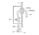
前記鋼管支柱1の前記カメラ2a、照明機器2b、制御装置3、蓄電池ボックス3a、太陽電池パネル5の取付け場所に臨む箇所に、それぞれケーブル挿通孔12,13が形成されており、前記配線されたケーブル10は、その両端10a,10aが前記各ケーブル挿通孔12,13にブッシュ12a,13aを介して挿通された状態で前記鋼管支柱1に固定されている。
前記鋼管支柱1の内部に、前記カメラ2a、照明機器2b、制御装置3、蓄電池ボックス3a、太陽電池パネル5の相互間を結ぶことによりそのカメラ2a、照明機器2b等を動作させるケーブル10が配線されている。このケーブル10の配線は、前記鋼管支柱1の製造後、出荷される前に施工される。
A
前記各ケーブル挿通孔12,13に挿通されたケーブル10は、その両端10a,10aに、対応する前記カメラ2a、照明機器2b、制御装置3、蓄電池ボックス3a、太陽電池パネル5の端子に接続可能な形態の端子14が取付けられており、また、両端10a,10aには、それぞれそのケーブル10の端子14の接続先を理解できる表示を付したタグ11が外部から視認可能に取付けられている(図3参照)。
The
また、前記ケーブル入線孔4aやケーブル挿通孔12,13周囲に、ケーブル10を保持することにより、その支柱1内におけるケーブル10の取り回し状態を維持する機能を有する張力止め15が設けられている。この張力止め15は、ケーブル10の端部10aを支柱の外部で保持しているので、ケーブル10が支柱1内に入り込んでしまうことがない。
A
以下、作業手順を説明すると、街路に既に建柱された鋼管支柱1のブラケット6,7に、前記カメラ2a、照明機器2b、制御装置3、蓄電池ボックス3a、太陽電池パネル5等を固定する。
Hereinafter, the work procedure will be described. The
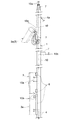
鋼管支柱1の内部には、予め、図2に示すように、ケーブル10が配線されているので、その各ケーブル10の端子14を、支柱1に取付けた前記カメラ2a、照明機器2b、制御装置3、蓄電池ボックス3a、太陽電池パネル5の対応する端子に接続するとともに、制御装置3に電源ケーブル4を接続(結線)する手順で行われる。
As shown in FIG. 2,
この接続の際、作業者は、タグ11に記載された内容を目視で確認することにより、対応する前記カメラ2a、照明機器2b、制御装置3、蓄電池ボックス3a、太陽電池パネル5を理解できるので、誤接続(誤結線)を防止し得るようになっている。
At the time of this connection, the operator can understand the
なお、そのケーブル10の端部10aに取付けた端子(圧着端子)14が、その接続先の機器に対応した態様となっていることはもちろんである。
Of course, the terminal (crimp terminal) 14 attached to the
この実施例では、カメラ2a及び照明機器2bに電源を供給するためのソーラ発電装置(蓄電池ボックス3a、太陽電池パネル5等)を備え、また、蓄電池ボックス3aには、電源ケーブル4が接続されているので商用電源が供給可能である。このため、各機器2a,2bの動作に必要な電気を、ソーラ発電装置(蓄電池ボックス3a、太陽電池パネル5等)と商用電源とから選択的に供給することができる。このため、例えば、日照時間が短い時など、充電が充分にできない場合は、ソーラ発電装置(蓄電池ボックス3a、太陽電池パネル5等)からの電気の供給に加え又は代えて、商用電源から電気を供給することもできる。もちろん、必要に応じて、ソーラ発電装置(蓄電池ボックス3a、太陽電池パネル5等)の設置を省略することもできるし、逆に、ソーラ発電装置(蓄電池ボックス3a、太陽電池パネル5等)のみで電源を賄い、商用電源からの電気の供給を行わないようにすることもできる。
In this embodiment, a solar power generation device (
1 鋼管支柱(支柱)
2 電気機器
2a カメラ
2b 照明機器
3 制御装置
3a 蓄電池ボックス
4 電源ケーブル
5 太陽電池パネル
6,7 ブラケット
10 ケーブル(配線ケーブル)
11 タグ
12,13 ケーブル挿通孔
12a,13a ブッシュ
14 端子
15 張力止め
1 Steel pipe support (support)
2
11
Claims (6)
前記支柱(1)の内部に、前記電気機器(2)及び前記装置の相互間を結ぶことによりその電気機器(2)を動作させるケーブル(10)を、前記支柱(1)の建柱前に配線したことを特徴とするケーブル内蔵型支柱。 The electric device (2) can be attached to the column (1) built on the street, and the device necessary for the operation of the electric device (2) can be attached. The electric device (2) and the device In the column (1) for attaching the column after the column of the column (1),
A cable (10) for operating the electric device (2) by connecting the electric device (2) and the device to each other inside the column (1) is provided in front of the building column of the column (1). Built-in cable-supported column characterized by wiring.
前記支柱(1)の内部に、前記電気機器(2)と前記装置の相互間を結んでその電気機器(2)を動作させるケーブル(10)を前記支柱(1)の建柱前に配線し、その支柱(1)を建柱した後、その支柱(1)に前記電気機器(2)と前記装置を取付けるとともに、その後、前記電気機器(2)と前記装置の相互間を前記ケーブル(10)で結ぶことを特徴とする支柱へのケーブル配線方法。 Between the electric device (2) and the device inside a column (1) that is built on a street and can be mounted with the electric device (2) and a device necessary for the operation of the electric device (2). A cable wiring method to a support for wiring a cable (10) for operating the electric device (2) by tying,
A cable (10) for operating the electric device (2) by connecting the electric device (2) and the device to each other inside the column (1) is wired before the building column of the column (1). After the column (1) is built, the electric device (2) and the device are attached to the column (1), and then the cable (10) is connected between the electric device (2) and the device. ) Is a cable wiring method to a support.
Priority Applications (1)
| Application Number | Priority Date | Filing Date | Title |
|---|---|---|---|
| JP2008315731A JP5369326B2 (en) | 2008-12-11 | 2008-12-11 | Built-in cable support |
Applications Claiming Priority (1)
| Application Number | Priority Date | Filing Date | Title |
|---|---|---|---|
| JP2008315731A JP5369326B2 (en) | 2008-12-11 | 2008-12-11 | Built-in cable support |
Publications (2)
| Publication Number | Publication Date |
|---|---|
| JP2010142017A true JP2010142017A (en) | 2010-06-24 |
| JP5369326B2 JP5369326B2 (en) | 2013-12-18 |
Family
ID=42351633
Family Applications (1)
| Application Number | Title | Priority Date | Filing Date |
|---|---|---|---|
| JP2008315731A Expired - Fee Related JP5369326B2 (en) | 2008-12-11 | 2008-12-11 | Built-in cable support |
Country Status (1)
| Country | Link |
|---|---|
| JP (1) | JP5369326B2 (en) |
Cited By (4)
| Publication number | Priority date | Publication date | Assignee | Title |
|---|---|---|---|---|
| CN106568059A (en) * | 2016-10-21 | 2017-04-19 | 钟立朋 | Multi-function street lamp |
| JP2018048461A (en) * | 2016-09-21 | 2018-03-29 | 住友商事株式会社 | Multifunctional structure |
| CN108848349A (en) * | 2018-07-13 | 2018-11-20 | 成都福立盟科技有限公司 | A kind of data collection system of management easy to produce |
| CN115613487A (en) * | 2022-09-30 | 2023-01-17 | 合肥市规划设计研究院 | A fixing device and fixing method for a load-carrying rod on a composite rod |
Families Citing this family (3)
| Publication number | Priority date | Publication date | Assignee | Title |
|---|---|---|---|---|
| JP7524965B2 (en) * | 2020-11-06 | 2024-07-30 | 日本電信電話株式会社 | Method for adjusting tension of utility pole and optical cable |
| KR102342820B1 (en) * | 2021-03-11 | 2021-12-23 | 이원목 | Modular-combined smart pole for building a smart city |
| KR102429277B1 (en) * | 2021-11-24 | 2022-08-08 | 주식회사 가보테크 | Modular-combined smart poles for building smart cities equipped with electric vehicle charging stations |
Citations (5)
| Publication number | Priority date | Publication date | Assignee | Title |
|---|---|---|---|---|
| JPS4934529U (en) * | 1972-06-21 | 1974-03-27 | ||
| JPS5136235Y1 (en) * | 1970-12-27 | 1976-09-06 | ||
| JPS533099A (en) * | 1976-06-29 | 1978-01-12 | Takashi Itonaga | Pole for signaling lamp |
| JPH10126914A (en) * | 1996-10-15 | 1998-05-15 | Hitachi Electron Service Co Ltd | Wiring discriminating method and apparatus with discrimination mark at cable laying |
| JP2004343868A (en) * | 2003-05-14 | 2004-12-02 | Kokuyo Denko Kk | Cable lead-in part structure and cable lead-in method |
-
2008
- 2008-12-11 JP JP2008315731A patent/JP5369326B2/en not_active Expired - Fee Related
Patent Citations (5)
| Publication number | Priority date | Publication date | Assignee | Title |
|---|---|---|---|---|
| JPS5136235Y1 (en) * | 1970-12-27 | 1976-09-06 | ||
| JPS4934529U (en) * | 1972-06-21 | 1974-03-27 | ||
| JPS533099A (en) * | 1976-06-29 | 1978-01-12 | Takashi Itonaga | Pole for signaling lamp |
| JPH10126914A (en) * | 1996-10-15 | 1998-05-15 | Hitachi Electron Service Co Ltd | Wiring discriminating method and apparatus with discrimination mark at cable laying |
| JP2004343868A (en) * | 2003-05-14 | 2004-12-02 | Kokuyo Denko Kk | Cable lead-in part structure and cable lead-in method |
Cited By (6)
| Publication number | Priority date | Publication date | Assignee | Title |
|---|---|---|---|---|
| JP2018048461A (en) * | 2016-09-21 | 2018-03-29 | 住友商事株式会社 | Multifunctional structure |
| CN106568059A (en) * | 2016-10-21 | 2017-04-19 | 钟立朋 | Multi-function street lamp |
| CN108848349A (en) * | 2018-07-13 | 2018-11-20 | 成都福立盟科技有限公司 | A kind of data collection system of management easy to produce |
| CN108848349B (en) * | 2018-07-13 | 2020-10-16 | 成都福立盟科技有限公司 | Data acquisition system convenient to production management |
| CN115613487A (en) * | 2022-09-30 | 2023-01-17 | 合肥市规划设计研究院 | A fixing device and fixing method for a load-carrying rod on a composite rod |
| CN115613487B (en) * | 2022-09-30 | 2025-07-11 | 合肥市规划设计研究院 | A fixing device and fixing method of a bearing rod on a comprehensive rod |
Also Published As
| Publication number | Publication date |
|---|---|
| JP5369326B2 (en) | 2013-12-18 |
Similar Documents
| Publication | Publication Date | Title |
|---|---|---|
| JP5369326B2 (en) | Built-in cable support | |
| KR101176940B1 (en) | Steel pole for multifunctional traffic facility | |
| JP4119476B1 (en) | Outdoor lights | |
| CN104930448A (en) | Solar integrated road lamp | |
| JP2007146524A (en) | Prop support device | |
| KR20140127542A (en) | Portable apparatus for equipping tower of wind turbine | |
| KR101467693B1 (en) | Apparatus for hoist flag | |
| US20040159027A1 (en) | Electronic display board supporting structure | |
| CN205663253U (en) | Fast dismouting housing construction | |
| KR100618523B1 (en) | Optical cable spare organizer | |
| JP3844250B2 (en) | Canopy equipment | |
| JP5105994B2 (en) | Broken pole repair device and broken pole repair method using the same | |
| CN203805819U (en) | Automobile distribution box | |
| CN108666837A (en) | A kind of low pressure emergency service attachment device | |
| JP2008291432A (en) | Installation equipment with protective sheet and construction method for wind and rain | |
| CN214456362U (en) | Energy-concerving and environment-protective type is hanger for construction | |
| JP4125335B2 (en) | Solar cell module | |
| JP3238795U (en) | Fall prevention structure for lighting device and fall prevention tool | |
| CN109386795A (en) | A kind of power transmission line steel pipe rod structure of solar street light | |
| CN205617879U (en) | Transmission line salvagees overhead line pole | |
| JP5139243B2 (en) | Steel pipe column | |
| CN220827132U (en) | A climbing frame for manhole inspection | |
| CN215254751U (en) | Positioning device for embedded bolt at top of concrete column and embedded bolt fixing structure | |
| CN216345110U (en) | Camera stand column | |
| CN212841237U (en) | LED street lamp convenient to maintain |
Legal Events
| Date | Code | Title | Description |
|---|---|---|---|
| A621 | Written request for application examination |
Free format text: JAPANESE INTERMEDIATE CODE: A621 Effective date: 20111130 |
|
| A977 | Report on retrieval |
Free format text: JAPANESE INTERMEDIATE CODE: A971007 Effective date: 20130328 |
|
| A131 | Notification of reasons for refusal |
Free format text: JAPANESE INTERMEDIATE CODE: A131 Effective date: 20130423 |
|
| A521 | Request for written amendment filed |
Free format text: JAPANESE INTERMEDIATE CODE: A523 Effective date: 20130621 |
|
| TRDD | Decision of grant or rejection written | ||
| A01 | Written decision to grant a patent or to grant a registration (utility model) |
Free format text: JAPANESE INTERMEDIATE CODE: A01 Effective date: 20130820 |
|
| A61 | First payment of annual fees (during grant procedure) |
Free format text: JAPANESE INTERMEDIATE CODE: A61 Effective date: 20130829 |
|
| R150 | Certificate of patent or registration of utility model |
Ref document number: 5369326 Country of ref document: JP Free format text: JAPANESE INTERMEDIATE CODE: R150 Free format text: JAPANESE INTERMEDIATE CODE: R150 |
|
| R250 | Receipt of annual fees |
Free format text: JAPANESE INTERMEDIATE CODE: R250 |
|
| R250 | Receipt of annual fees |
Free format text: JAPANESE INTERMEDIATE CODE: R250 |
|
| R250 | Receipt of annual fees |
Free format text: JAPANESE INTERMEDIATE CODE: R250 |
|
| R250 | Receipt of annual fees |
Free format text: JAPANESE INTERMEDIATE CODE: R250 |
|
| R250 | Receipt of annual fees |
Free format text: JAPANESE INTERMEDIATE CODE: R250 |
|
| R250 | Receipt of annual fees |
Free format text: JAPANESE INTERMEDIATE CODE: R250 |
|
| LAPS | Cancellation because of no payment of annual fees |