JP2010142015A - Motor control device and image forming apparatus using the same - Google Patents
Motor control device and image forming apparatus using the same Download PDFInfo
- Publication number
- JP2010142015A JP2010142015A JP2008315695A JP2008315695A JP2010142015A JP 2010142015 A JP2010142015 A JP 2010142015A JP 2008315695 A JP2008315695 A JP 2008315695A JP 2008315695 A JP2008315695 A JP 2008315695A JP 2010142015 A JP2010142015 A JP 2010142015A
- Authority
- JP
- Japan
- Prior art keywords
- motor
- control
- speed
- control device
- signal
- Prior art date
- Legal status (The legal status is an assumption and is not a legal conclusion. Google has not performed a legal analysis and makes no representation as to the accuracy of the status listed.)
- Pending
Links
Images
Landscapes
- Control Or Security For Electrophotography (AREA)
- Control Of Motors That Do Not Use Commutators (AREA)
Abstract
Description
本発明はモータの駆動方法および制御装置に関するものであり、また、電子写真式あるいは静電記録式の複写装置、画像記録装置、プリンタファクシミリなどの画像形成装置に関するものである。 The present invention relates to a motor driving method and a control device, and also relates to an image forming apparatus such as an electrophotographic or electrostatic recording type copying apparatus, an image recording apparatus, and a printer facsimile.
従来のモータ制御装置を図1を参照して説明する。 A conventional motor control apparatus will be described with reference to FIG.
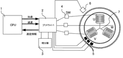
図1は3相のブラシレスモータの構成を示したもので、図において、1はCPUで予め設定された速度とモータから得た速度情報とにより、制御量を演算し、制御信号である加速信号、減速信号を2のプリドライバへ送信する。2のプリドライバでは1のCPUから送信された加速減速信号を、3の積分器によりモータのトルク指令に変換する。また、5の磁気センサにより検知したモータの永久磁石の位置から、7の3相コイルへ電流を流すタイミングを生成し、そのタイミングに応じて4のSWをオンオフする。
Fig. 1 shows the configuration of a three-phase brushless motor. In the figure, 1 is an acceleration signal that is a control signal by calculating a control amount based on a speed preset by the CPU and speed information obtained from the motor. Send a deceleration signal to the 2 pre-driver. The pre-driver 2 converts the acceleration / deceleration signal transmitted from the CPU 1 into a motor torque command by the
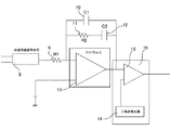
また、図2は図1の積分器3を詳細に示した図で、CPU1より送信される加速信号、減速信号により充放電される8のチャージポンプ回路、8のチャージポンプ回路の出力によりモータに対してトルク指令を発生する積分アンプ13よりなる。
FIG. 2 is a detailed diagram of the
8のチャージポンプ回路は加速信号により充電され、減速信号により放電される構成となっている。よって、モータ起動時は加速信号が入力され、チャージポンプ回路の出力電圧が上昇し、トルク指令が増加していく。モータが所望の回転数になった時点で加速信号の送信を中止し、その状態にてホールドさせる。モータの負荷トルクが変動した場合は加速信号、減速信号により調整を行う構成である。
The
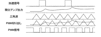
積分アンプ13の出力は比較器15に入力され、14の三角波発生器で生成された三角波と比較した値を出力することでPWM信号を作り出している。信号の関係は図3に示すとおりである。14、15をまとめてPWM生成手段16とする。このPWM信号は7のコイルに電流を流すための4のSWに入力され、所望の電流がコイルに流れるようになっている。モータがこのとき発生する出力トルク(負荷)T、トルク定数KT、モータに流れる電流をIとすると、以下の式が成り立つため、加速減速信号により、モータの速度を制御することが可能となっている。
The output of the integrating
T=KT×I
しかしながら、この方式では、積分アンプ13の特性を決めるための定数が抵抗やコンデンサなどの固定部品で構成されているため、負荷変動の周波数やモータの回転数が広範な場合、すべての範囲に最適なモータ制御を行うということが不可能であった。
T = K T × I
However, with this method, the constants that determine the characteristics of the integrating
上記課題を解決するための方法として、広範な回転数において最適なモータ制御を実現するためにゲインを自動調整する方式が知られている。(特許文献1参照)。 As a method for solving the above-described problem, there is known a method of automatically adjusting a gain in order to realize optimum motor control in a wide range of rotation speeds. (See Patent Document 1).
あるいはゲインをアナログスイッチを用いて切り替える方式が知られている。(特許文献2参照)。
しかしながら、従来の方式では自動調整する場合は回路が複雑で多くなり、かつ制御手段(例えばCPU)の負荷が大きくなり、モータ制御専用のICを採用するなど、コストがかかっていた。また、アナログスイッチ方式ではスイッチを切り替えるための信号線が必要でコストがかかってしまっていた。 However, in the conventional method, when automatic adjustment is performed, the circuit becomes complicated and increases, and the load on the control means (for example, CPU) increases, and an IC for exclusive use for motor control is employed. Further, the analog switch method requires a signal line for switching the switch, which is expensive.
本発明は上述した課題を解決するためになされたものであり、以下の構成を備える。 The present invention has been made to solve the above-described problems, and includes the following configuration.
第1の発明は、複数種の制御信号により制御可能なモータと、該モータの速度を制御する制御手段とを備え、該制御手段はモータの速度情報をもとに制御量を算出する制御量算出手段と、制御量をモータへ出力するための制御信号を複数種出力することが可能な出力手段と、出力する制御信号を切り替える出力切り替え手段とを備えたモータ制御装置において、制御するモータの速度に応じて、制御手段で出力する制御信号の種類を切り替えることを特徴とする。 A first invention includes a motor that can be controlled by a plurality of types of control signals, and a control unit that controls the speed of the motor, and the control unit calculates a control amount based on motor speed information. In a motor control device comprising: a calculating means; an output means capable of outputting a plurality of types of control signals for outputting control amounts to the motor; and an output switching means for switching the control signals to be output. The type of the control signal output by the control means is switched according to the speed.
第2の発明は、第1の発明のモータ制御装置において、モータの速度情報が予め設定された速度設定値より遅い場合は加速信号を送信し、速度設定値より速い場合は減速信号を送信することにより、モータの速度を制御する方式と、PWM信号を用いてモータの速度を制御する方式とを切り替えることを特徴とする。 According to a second invention, in the motor control device of the first invention, an acceleration signal is transmitted when the motor speed information is slower than a preset speed set value, and a deceleration signal is transmitted when the motor speed information is faster than the speed set value. Thus, the method of switching the motor speed and the method of controlling the motor speed using a PWM signal are switched.
第3の発明は、第1の発明、又は第2の発明のモータ制御装置において、制御信号を切り替える場合に、制御信号を出力するための信号線は、制御信号を切り替える前と共通の信号線を使用することを特徴とする。 According to a third aspect of the present invention, in the motor control device of the first aspect or the second aspect, when the control signal is switched, the signal line for outputting the control signal is the same signal line as before the control signal is switched. It is characterized by using.
第4の発明は、第1の発明〜第3の発明のいずれかに記載のモータ制御装置において、設定されたモータの速度設定値に応じて制御信号を切り替えるとともに、制御量算出手段で算出する制御量の算出方式も切り替えることを特徴とする。 According to a fourth invention, in the motor control device according to any one of the first to third inventions, the control signal is switched according to the set speed setting value of the motor, and is calculated by the control amount calculation means. The control amount calculation method is also switched.
第5の発明は、第4の発明のモータ制御装置において、モータの速度情報と、モータを制御するために予め設定されたモータの速度設定値との差分に比例ゲインをかけて制御量を算出する比例制御と、比例ゲインをかけた制御量に、差分を時間微分、時間積分をしたものを加えて制御量を算出する制御とを切り替えることを特徴とする。 According to a fifth aspect of the present invention, in the motor control device of the fourth aspect of the invention, a control amount is calculated by multiplying a difference between the motor speed information and a motor speed setting value set in advance to control the motor by a proportional gain. Switching between proportional control and control for calculating a control amount by adding a time differential and time integral to a control amount multiplied by a proportional gain.
第6の発明は、第1の発明〜第5の発明のいずれかに記載のモータ制御装置において、モータの速度情報と、予め設定されたモータの速度設定値からモータの速度のズレを検出し、速度のズレ量に応じて制御手段で出力する制御信号を切り替えることを特徴とする。 According to a sixth invention, in the motor control device according to any one of the first to fifth inventions, a motor speed deviation is detected from the motor speed information and a preset motor speed setting value. The control signal output by the control means is switched according to the amount of speed deviation.
第7の発明は、第1の発明〜第5の発明のいずれかに記載のモータ制御装置において、モータへ出力する制御量の変動を所定期間モニタし、制御量の変動の大きさに応じて制御手段で出力する制御信号を切り替えることを特徴とする。 According to a seventh aspect of the present invention, in the motor control device according to any one of the first to fifth aspects, the fluctuation of the control amount output to the motor is monitored for a predetermined period, and according to the magnitude of the fluctuation of the control amount The control signal output by the control means is switched.
第8の発明は、第1の発明〜第7の発明のいずれかに記載のモータ制御装置を搭載した画像形成装置。 An eighth invention is an image forming apparatus equipped with the motor control device according to any one of the first to seventh inventions.
第9の発明は、第8の発明の画像形成装置において、複数の画像形成のためのプロセス速度を持った画像形成装置であって、プロセス速度に応じてモータ制御装置の制御方法を切り替えることを特徴とする。 A ninth invention is an image forming apparatus having process speeds for forming a plurality of images in the image forming apparatus of the eighth invention, wherein the control method of the motor control device is switched according to the process speed. Features.
第10の発明は、第1の発明〜第7の発明のモータ制御装置において、制御するモータがDCモータであることを特徴とする。 According to a tenth aspect, in the motor control device according to the first to seventh aspects, the motor to be controlled is a DC motor.
第11の発明は、第10の発明のモータ制御装置において、制御するモータがインナーロータタイプのDCモータであることを特徴とする。 The eleventh invention is characterized in that, in the motor control device of the tenth invention, the motor to be controlled is an inner rotor type DC motor.
以上説明したように、本発明によれば、モータの速度に応じた最適な制御を低コストで行うことが可能となり、特に画像形成装置においては、安価に高画質化を図ることができる。 As described above, according to the present invention, it is possible to perform optimum control in accordance with the speed of the motor at low cost, and in particular, in an image forming apparatus, high image quality can be achieved at low cost.
次に、本発明の詳細を実施例の記述に従って説明する。 Next, details of the present invention will be described in accordance with the description of the embodiments.
以下、本発明を図4に示す実施例に基いて詳細に説明する。 Hereinafter, the present invention will be described in detail based on the embodiment shown in FIG.
本発明の実施例に係るモータ制御装置の構成は図1と同様である。 The configuration of the motor control device according to the embodiment of the present invention is the same as that shown in FIG.
同図において、制御信号を切り替え可能なモータ制御装置を実現している。その他の構成および動作は従来例と同様なので説明を省略する。 In the figure, a motor control device capable of switching control signals is realized. Other configurations and operations are the same as those of the conventional example, and thus description thereof is omitted.
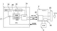
図4に本装置の制御システムの概略構成を示す。 FIG. 4 shows a schematic configuration of the control system of this apparatus.
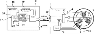
17はモータを所定の速度で制御するための速度ターゲット18とモータから得た速度情報との差分を算出する差分演算部、19は速度ターゲットに応じて制御方式を切り替えるための制御切り替え手段、20は演算部で、制御切り替え判定手段の出力に応じて演算方式を切り替える構成となっている。本実施例においては一例としてP制御(比例制御)とPID制御(比例積分微分制御)とが切り替えられる構成としているものの、切り替える制御方式は問わないものとする。21は出力部で制御切り替え判定手段の出力に応じてモータのプリドライバへ送出する信号を加速減速信号とPWM信号とを切り替える。22はプリドライバに設けられた受信信号切り替え手段で、制御部であるCPU1から受信する信号の種類に応じて、信号の伝達先を切り替える。加速減速信号の場合は3の積分器へ接続し、PWM信号の場合は直接コイルに通電するためのスイッチ群23へ接続を行う。
17 is a difference calculation unit for calculating the difference between the
次に本実施形態に係る上記構成のモータ制御装置の動作を説明する。 Next, the operation of the motor control device having the above configuration according to the present embodiment will be described.
まず、モータを駆動するために速度ターゲット18を設定する。設定された速度ターゲットに応じて制御切り替え判定手段にて制御方式および出力制御信号を切り替える。切り替える基準はそのモータの使用する速度レンジに応じて、任意に設定できる構成である。モータは速度が低速であるほど、回転ムラが悪化するため、より高精度な制御が必要である。よって、本実施例においては設定した基準より速度ターゲット18が小さい場合に、演算部20での演算をPID制御を選択することとする。また、モータの制御性を向上させるため、モータ側に備えられている積分器3とPWM信号発生手段16を使用することなく、21の出力部からPWM信号を送出し、23のスイッチ群のON/OFFに使用する。23のスイッチ群のON/OFFに従い、コイル7へ電流が流れる。速度ターゲットに対してモータから得られた速度情報が遅かった場合はPWM信号のON_DUTYが大きくなるように制御し、モータから得られた速度情報が速かった場合はPWM信号のON_DUTYが小さくなるように制御することで、モータの速度が速度ターゲットと一致するように制御を行う。
First, the
22の受信信号切り替え手段においては、例えば、PWM信号を送出する前に、減速信号の信号線を使って、減速信号を送信する周期より速い周期で信号を送信することにより、それをコマンドとして扱うことで切り替え手段のモードを切り替える構成とする。その他、加速信号、減速信号の送信タイミングなどを組み合わせることによりモードを切り替える構成としても良い。 In the reception signal switching means of 22, for example, before sending the PWM signal, the signal is transmitted at a cycle faster than the cycle of transmitting the deceleration signal by using the signal line of the deceleration signal, so that it is handled as a command. Thus, the mode of the switching means is switched. In addition, it is good also as a structure which switches a mode by combining the transmission timing of an acceleration signal, a deceleration signal, etc.
速度ターゲット18が制御手段を切り替える基準よりも大きくした場合は、制御切り替え判定手段19で20の演算部の演算方式をP制御に切り替える。また、出力部で出力する制御信号も加速減速信号に切り替える。このとき減速信号の信号線を使ってコマンドを送信し、2のプリドライバに制御信号の切り替わりを伝える。2のプリドライバは、入力された加速減速信号を3の積分器へ接続し、積分された値と16のPWM信号生成器により23のスイッチ群へPWM信号を送出し、23のスイッチ群のON/OFFを行う。23のスイッチ群のON/OFFに従い、コイル7へ電流が流れる。速度ターゲットに対してモータから得られた速度情報が遅かった場合は加速信号を送信し、モータから得られた速度情報が速かった場合は減速信号を送信することで、モータの速度が速度ターゲットと一致するように制御を行う。
When the
以上の構成により、信号線を追加することなく、モータの駆動速度に応じて制御方式を切り替えることが可能となり、モータの速度に応じた最適制御を実現することができる。 With the above configuration, the control method can be switched according to the driving speed of the motor without adding a signal line, and optimal control according to the speed of the motor can be realized.
以下、本発明を図5に示す実施例に基いて詳細に説明する。 Hereinafter, the present invention will be described in detail based on the embodiment shown in FIG.
本発明の実施例に係るモータ制御装置の主な構成は図1と同様である。 The main configuration of the motor control device according to the embodiment of the present invention is the same as that shown in FIG.
同図において、制御信号を切り替え可能なモータ制御装置を実現している。他の構成および動作は従来例と同様なので説明を省略する。 In the figure, a motor control device capable of switching control signals is realized. Since other configurations and operations are the same as those of the conventional example, the description thereof is omitted.
図5において24は設定された速度ターゲットとモータから得られた速度情報との差分を17により算出し、算出した値の大きさをモニタするための差分モニタ手段。25は速度検出手段で強磁性磁気抵抗効果型素子などにより、ロータに均等に着磁されたパターンを、ロータの回転スピードに応じたSin波形として読み取り、波形変換器により矩形のパルス波(例えば500パルス/回転)に変換した速度情報を制御手段へ出力する。速度検出手段にはその他にロータ近傍に形成したFGパターンによる回転速度検出や、円周に沿って等間隔にスリットのある円盤と、フォトインタラプタ(光透過型センサ)から構成されるエンコーダなどが用いられる。 In FIG. 5, 24 is a difference monitoring means for calculating the difference between the set speed target and the speed information obtained from the motor by 17, and monitoring the magnitude of the calculated value. 25 is a speed detection means that reads a pattern magnetized evenly on the rotor by a ferromagnetic magnetoresistive element or the like as a Sin waveform corresponding to the rotational speed of the rotor, and a rectangular pulse wave (eg, 500 The speed information converted into (pulse / rotation) is output to the control means. In addition, the speed detection means uses an FG pattern formed near the rotor, a rotational speed detection, a disk with slits at equal intervals along the circumference, and an encoder composed of a photo interrupter (light transmission sensor). It is done.
次に本実施形態に係る上記構成のモータ制御装置の動作を説明する。 Next, the operation of the motor control device having the above configuration according to the present embodiment will be described.
まず、モータを駆動するために速度ターゲット18を設定する。設定された速度ターゲットと25の速度検出手段で得られたモータの速度情報を比較し、17の差分算出部にて差分を算出する。モータ駆動開始時はP制御が選択され、演算部20では算出された差分に対して、比例ゲインをかけた制御量が出力される。このとき21の出力部においては加速信号および減速信号をプリドライバ2へ送信することが選択され、モータの速度情報が速度ターゲットより遅い場合は加速信号を、速度ターゲットより速い場合は減速信号をプリドライバへ送信する。
First, the
この制御を26のタイマにセットされた時間T1の間継続させる。T1はモータ駆動開始速度が安定するまでに十分な時間とする。T1経過後、24の偏差モニタで所定期間T2の間偏差の振幅を計測する。偏差の振幅は速度が遅かった場合の偏差をed、その累積値Ed、速度が速かった場合の偏差ef、その累積値Efとすると次式により算出する。 This control is continued for the time T1 set in the 26 timer. T1 is set to a sufficient time until the motor drive start speed is stabilized. After T1, the deviation amplitude is measured for a predetermined period T2 with 24 deviation monitors. The amplitude of the deviation is calculated by the following equation, where ed is the deviation when the speed is slow, its accumulated value Ed, deviation ef when the speed is fast, and its accumulated value Ef.
ES=│Ed│+│Ef│
Ed=Σed(T2間の累積)
Ef=Σef(T2間の累積)
算出されたESの値が制御切り替えのしきい値Eよりも大きい場合は、制御切り替え判定手段19により制御を切り替える処理を行う。具体的には演算部20での制御をP制御からPID制御へ切り替えかつ、出力部21でモータのプリドライバへ送出する信号を加速減速信号からPWM信号へと切り替える。2のプリドライバに設けられた受信信号切り替え手段で、PWM信号を直接23のスイッチ群へ接続する処理を行う。接続を切り替えて以降はモータの速度を切り替える、あるいは停止するまで同じモードにて制御を継続させる。
ES = │Ed│ + │Ef│
Ed = Σed (cumulative between T2)
Ef = Σef (cumulative between T2)
When the calculated ES value is larger than the control switching threshold value E, the control switching determining
PWM信号での制御においては速度ターゲットに対してモータから得られた速度情報が遅かった場合はPWM信号のON_DUTYが大きくなるように制御し、モータから得られた速度情報が速かった場合はPWM信号のON_DUTYが小さくなるように制御することで、モータの速度が速度ターゲットと一致するように制御を行う。 In the control with the PWM signal, if the speed information obtained from the motor with respect to the speed target is slow, control is performed so that the ON_DUTY of the PWM signal becomes large, and if the speed information obtained from the motor is fast, the PWM signal By controlling so that ON_DUTY of the motor becomes smaller, control is performed so that the motor speed matches the speed target.
22の受信信号切り替え手段においては、例えば、PWM信号を送出する前に、減速信号の信号線を使って、減速信号を送信する周期より速い周期で信号を送信することにより、それをコマンドとして扱うことで切り替え手段のモードを切り替える構成とする。その他、加速信号、減速信号の送信タイミングなどを組み合わせることによりモードを切り替える構成としても良い。 In the reception signal switching means of 22, for example, before sending the PWM signal, the signal is transmitted at a cycle faster than the cycle of transmitting the deceleration signal by using the signal line of the deceleration signal, so that it is handled as a command. Thus, the mode of the switching means is switched. In addition, it is good also as a structure which switches a mode by combining the transmission timing of an acceleration signal, a deceleration signal, etc.
次に以上の構成における位相補正の実施形態を図6を用いて説明する。 Next, an embodiment of phase correction in the above configuration will be described with reference to FIG.
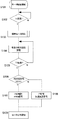
モータを駆動開始後(S101)、タイマにセットされたT1の時間だけ待つ(S102)。T1経過したところで速度ターゲットとモータの速度情報との差分である偏差のモニタを開始する(S103)。このモニタはT2の間継続させる。また、モニタ中に偏差の絶対値を累積させる(S104、S105)。T2経過したときの累積値ESが制御方式を切り替えるための閾値ECより大きい場合は制御をPID制御に切り替える(S106,S107)。ESがECより小さい場合はP制御かつ加速減速信号とする(S108)。制御方式が決定した後は制御方式を固定し定常制御を行う(S109)。 After starting the motor (S101), the system waits for the time T1 set in the timer (S102). When T1 has elapsed, monitoring of the deviation, which is the difference between the speed target and the motor speed information, is started (S103). This monitor is continued for T2. Further, the absolute value of the deviation is accumulated during monitoring (S104, S105). If the accumulated value ES when T2 has elapsed is larger than the threshold EC for switching the control method, the control is switched to PID control (S106, S107). When ES is smaller than EC, P control and acceleration / deceleration signal are used (S108). After the control method is determined, the control method is fixed and steady control is performed (S109).
以上の構成により、信号線を追加することなく、モータの駆動速度に応じて制御方式を切り替えることが可能となり、モータの速度に応じた最適制御を実現することができる。 With the above configuration, the control method can be switched according to the driving speed of the motor without adding a signal line, and optimal control according to the speed of the motor can be realized.
以下、本発明を図7に示す実施例に基いて詳細に説明する。 Hereinafter, the present invention will be described in detail based on the embodiment shown in FIG.
本発明の実施例に係るモータ制御装置の主な構成は図1と同様である。 The main configuration of the motor control device according to the embodiment of the present invention is the same as that shown in FIG.
同図において、制御信号を切り替え可能なモータ制御装置を搭載した画像形成装置を実現している。他の構成および動作は従来例と同様なので説明を省略する。 In the figure, an image forming apparatus equipped with a motor control device capable of switching control signals is realized. Since other configurations and operations are the same as those of the conventional example, the description thereof is omitted.
以下、本発明を図7の実施例に基いて詳細に説明する。 Hereinafter, the present invention will be described in detail based on the embodiment of FIG.
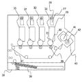
図7は本発明の特徴をよくあらわした図面であり、図において27はスキャナユニットであり不図示の半導体レーザと28の回転多面鏡により構成される。29は現像剤(トナー)格納および30の像担持体上の余剰トナーをクリーニングしたときに発生する廃トナーを格納するためのカートリッジ。31は像担持体表面の静電潜像をトナー像へと現像する現像スリーブであり、30の像担持体と接離可能な構成となっており、画像形成時に当接し、画像形成時以外は離間している。32は29,30,31をまとめて現像装置(以下現像カートリッジ)とし、32,33,34,35,はそれぞれイエローY、マゼンタM、シアンC、ブラックBKの現像カートリッジであり、特にその順序は問わないものとする。36は各色現像カートリッジにより現像された像担持体30上のトナー像を印字媒体へと転写するために像担持体に対向して配設された転写ローラ。37は印字媒体を搬送するため無端ベルトにより構成された搬送ベルト。38は給紙ユニット。39は給紙ユニット内に搭載された印字媒体を表す。40は印字媒体上のトナー像を印字媒体へ定着させるための定着器、41は定着ローラ、42は定着させるために定着器を加熱するためのヒータローラである。
FIG. 7 is a diagram showing the features of the present invention. In FIG. 7,
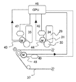
図8は図7の主に搬送ベルト駆動部と現像駆動部を模式的に示したもので、本実施例に係るモータ制御部を示したものである。 FIG. 8 schematically shows mainly the conveyance belt drive unit and the development drive unit of FIG. 7, and shows the motor control unit according to this embodiment.
図8において、43はブラックの現像カートリッジを駆動するためのモータで、このモータを駆動することによりカートリッジ内の感光体30と現像スリーブ31を回転駆動させることができる。44はシアンの現像カートリッジを駆動するためのモータ。45は37の搬送ベルトを駆動するためのモータ。46は画像形成装置に備えられたCPUでありモータの制御や駆動開始、停止などのタイミングを制御している。47、48は画像形成系の現像装置のモータを駆動するためのモータドライバで、49は搬送ベルトを駆動するモータのモータドライバである。
In FIG. 8,
本実施例においては特に43、44、45のモータにDCブラシレスモータを採用したものについて述べる。
In this embodiment, a case where a DC brushless motor is adopted as the
上記構成の画像形成装置について動作説明を行う。モータ制御ブロックについては図3および実施例1で説明したところと同様であるので詳細な説明は省略する。 The operation of the image forming apparatus having the above configuration will be described. Since the motor control block is the same as that described in FIG. 3 and the first embodiment, detailed description thereof is omitted.
画像データを受けると、まず46のCPUはユーザに設定された紙種あるいは印字モードに応じて18の速度ターゲットに速度を設定する。制御切り替え判定手段では設定された速度ターゲットに応じて演算部の演算方式を切り替える。例えば、坪量60g/cm2〜105g/ cm2の印字媒体が選択された場合は画像形成装置における最も速い印字モードにて印字を行うため、演算部はP制御を選択し、出力部では加速減速信号方式を選択する。モータドライバも同様に加速減速信号でのモータ制御の処理を実行し、制御モードを設定する。
When the image data is received, the
一方、105g/ cm2より重い紙種やOHTあるいはグロスフィルムなどが選択された場合は、低速の印字モードにて印字を行うため、演算部はPID制御を選択し、出力部ではPWM信号方式を選択する。モータドライバも同様にPWM信号でのモータ制御の処理を実行し、制御モードを設定する。 On the other hand, when a paper type heavier than 105 g / cm 2 or OHT or gloss film is selected, the PID control is selected for the calculation unit and the PWM signal system is selected for the output unit to perform printing in the low-speed print mode. select. Similarly, the motor driver executes the motor control process with the PWM signal and sets the control mode.
モータの制御方式の設定終了後に43、44、45の各モータに対し駆動信号を送信する。そして、モータ駆動中は43、44、45それぞれのモータに取り付けられた速度検出手段により回転速度情報がCPU46へ送られる。モータはCPU46図3に示した制御ブロックにて各モータの回転速度が所定の速度になるように制御される。このとき43,44,45とその他のモータが目標の回転数に達すると45のCPUは画像形成プロセスを開始する。46のCPUは給紙動作を開始し、38の給紙ユニットにより内部に搭載された39の印字媒体を画像形成系の搬送駆動装置へ搬送する。画像形成系の先頭部へ搬送された印字媒体39は、画像形成時の最適速度(以下プロセス速度)で回転している37の搬送ベルトに吸着され、プロセス速度でBKの現像カートリッジ35の前縁へ搬送される。ここで35のBK現像カートリッジ内の感光体上に形成されたBKのトナー像を転写ローラ36により印字媒体上へ転写する。その後、搬送順にCの現像カートリッジによりCのトナー像が印字媒体上へ転写され、Mのトナー像、Yのトナー像と順次印字媒体上で重ね合わせ、最終的にフルカラーのトナー像が印字媒体上で形成される。
After the setting of the motor control method is completed, a drive signal is transmitted to each of the
印字媒体の先端は画像形成系の最下流にあるYのトナー像の転写が終わると搬送に従い画像形成系を脱し、40の定着器により印字媒体上のトナー像は加熱加圧され印字媒体上へ定着し、排紙される。 When the transfer of the Y toner image located at the most downstream side of the image forming system at the end of the printing medium is completed, the image forming system is removed according to the conveyance, and the toner image on the printing medium is heated and pressurized by the 40 fixing device onto the printing medium. It is fixed and discharged.
(他の実施形態)
上述の実施形態においては、画像形成装置の一例としてのレーザビームプリンタに本発明を適用した場合のみを説明した。しかしながら、本発明の本質はモータの速度制御を広範囲の速度域で安定させて行うことであり、本発明をレーザビームプリンタ以外の画像形成装置、例えばLEDプリンタや液晶プリンタ等の他のプリンタや、画像形成機能を有する任意の機器、例えば複写機やファクシミリ装置、複合機等にも適用可能である。
(Other embodiments)
In the above-described embodiment, only the case where the present invention is applied to the laser beam printer as an example of the image forming apparatus has been described. However, the essence of the present invention is that the speed control of the motor is performed stably in a wide speed range, and the present invention is applied to an image forming apparatus other than a laser beam printer, for example, another printer such as an LED printer or a liquid crystal printer, The present invention can also be applied to an arbitrary apparatus having an image forming function, such as a copying machine, a facsimile machine, and a multifunction machine.
1 CPU
2 プリドライバ
3 積分器
4 スイッチ
5 ホールセンサ
6 モータ速度検出センサ
7 モータコイル
8 加速減速信号合成回路
9 抵抗1
10 コンデンサ1
11 抵抗2
12 コンデンサ2
13 アンプ
14 三角波発生器
15 比較器
16 PWM生成器
17 差分演算部
18 速度ターゲット設定部
19 制御切り替え判定手段
20 制御量演算部
21 制御信号出力部
22 制御信号接続切り替え部
23 スイッチ群(コイル通電用)
24 偏差モニタ
25 モータ速度検出手段
26 タイマ
27 スキャナユニット
28 回転多面鏡
29 カートリッジ
30 像担持体
31 現像スリーブ
32 Y現像カートリッジ
33 M現像カートリッジ
34 C現像カートリッジ
35 BK現像カートリッジ
36 転写ローラ
37 搬送ベルト
38 給紙ユニット
39 印字媒体
40 定着器
41 定着ローラ
42 ヒータローラ
43 現像装置駆動モータ1
44 現像装置駆動モータ2
45 搬送ベルト駆動モータ
46 CPU(画像形成装置内)
47 モータ1用モータドライバ
48 モータ2用モータドライバ
49 モータ3用モータドライバ
1 CPU
2 Pre-driver 3
10 Capacitor 1
11
12
DESCRIPTION OF
24 Deviation monitor 25 Motor
44 Developing
45 Conveyor
47 Motor driver for motor 1 48 Motor driver for
Claims (11)
Priority Applications (1)
| Application Number | Priority Date | Filing Date | Title |
|---|---|---|---|
| JP2008315695A JP2010142015A (en) | 2008-12-11 | 2008-12-11 | Motor control device and image forming apparatus using the same |
Applications Claiming Priority (1)
| Application Number | Priority Date | Filing Date | Title |
|---|---|---|---|
| JP2008315695A JP2010142015A (en) | 2008-12-11 | 2008-12-11 | Motor control device and image forming apparatus using the same |
Publications (1)
| Publication Number | Publication Date |
|---|---|
| JP2010142015A true JP2010142015A (en) | 2010-06-24 |
Family
ID=42351631
Family Applications (1)
| Application Number | Title | Priority Date | Filing Date |
|---|---|---|---|
| JP2008315695A Pending JP2010142015A (en) | 2008-12-11 | 2008-12-11 | Motor control device and image forming apparatus using the same |
Country Status (1)
| Country | Link |
|---|---|
| JP (1) | JP2010142015A (en) |
Cited By (1)
| Publication number | Priority date | Publication date | Assignee | Title |
|---|---|---|---|---|
| JP2016187249A (en) * | 2015-03-27 | 2016-10-27 | カルソニックカンセイ株式会社 | Electric vehicle driving force control device |
-
2008
- 2008-12-11 JP JP2008315695A patent/JP2010142015A/en active Pending
Cited By (1)
| Publication number | Priority date | Publication date | Assignee | Title |
|---|---|---|---|---|
| JP2016187249A (en) * | 2015-03-27 | 2016-10-27 | カルソニックカンセイ株式会社 | Electric vehicle driving force control device |
Similar Documents
| Publication | Publication Date | Title |
|---|---|---|
| US6771919B2 (en) | Image forming apparatus with reduced variation of rotation speed of image carrier | |
| US9323208B2 (en) | Electric motor system and motor control method | |
| JP2020038313A (en) | Image forming apparatus | |
| JPH11136974A (en) | Actuator driving method, driving device, and image forming apparatus | |
| JP2013136454A (en) | Sheet conveying device, image forming apparatus, sheet thickness detection system, and sheet thickness detection program | |
| US9081344B2 (en) | Image forming apparatus with intermediate toner transfer medium, control method therefor, and storage medium storing control program therefor | |
| US8879960B2 (en) | Image bearing member drive unit that drives image bearing member, method of controlling image bearing member drive unit, storage medium, and image forming apparatus | |
| CN110196538B (en) | Image forming apparatus with a toner supply device | |
| JP7611656B2 (en) | Motor control device and image forming apparatus | |
| JP2010142015A (en) | Motor control device and image forming apparatus using the same | |
| JP5789247B2 (en) | Driving device, image forming apparatus, driving method, and image forming method | |
| JP2006163016A (en) | Image forming apparatus | |
| US20100316408A1 (en) | Cleaning control of image carrier in image forming apparatus | |
| US7443114B2 (en) | Image forming apparatus | |
| JP5258209B2 (en) | Stepping motor driving apparatus and image forming apparatus | |
| JP6354344B2 (en) | Image forming apparatus and motor control apparatus | |
| US20130142545A1 (en) | Image forming apparatus | |
| JP2000224878A (en) | Drive controller and picture forming apparatus using the same | |
| JP4078246B2 (en) | Motor control apparatus and image forming apparatus | |
| JP2010220434A (en) | Motor controller | |
| JP2003228255A (en) | Image recording device | |
| JP7814911B2 (en) | Image forming device | |
| JP2022060752A (en) | Image forming device | |
| JP2005181507A (en) | Image forming apparatus and speed control method thereof | |
| JP2006220939A (en) | Image forming apparatus and control method thereof |
Legal Events
| Date | Code | Title | Description |
|---|---|---|---|
| RD01 | Notification of change of attorney |
Free format text: JAPANESE INTERMEDIATE CODE: A7421 Effective date: 20100630 |