JP2010141980A - Electric power system monitor - Google Patents
Electric power system monitor Download PDFInfo
- Publication number
- JP2010141980A JP2010141980A JP2008313860A JP2008313860A JP2010141980A JP 2010141980 A JP2010141980 A JP 2010141980A JP 2008313860 A JP2008313860 A JP 2008313860A JP 2008313860 A JP2008313860 A JP 2008313860A JP 2010141980 A JP2010141980 A JP 2010141980A
- Authority
- JP
- Japan
- Prior art keywords
- lightning
- power system
- data
- operation procedure
- accident location
- Prior art date
- Legal status (The legal status is an assumption and is not a legal conclusion. Google has not performed a legal analysis and makes no representation as to the accuracy of the status listed.)
- Withdrawn
Links
Images


Landscapes
- Remote Monitoring And Control Of Power-Distribution Networks (AREA)
- Supply And Distribution Of Alternating Current (AREA)
Abstract
【課題】電力系統設備情報と発雷情報の両方を監視して、電力系統設備の状態変化が発雷の影響なのか否かを操作者が判断する必要がなく、判断ミスや判断の差が生じる虞がなく、停電箇所が最小となるような操作が実行可能な電力系統監視装置を提供する。
【解決手段】電力系統設備情報データ10と発雷情報データ11を入手して電力系統を監視する装置で、発雷情報データ11と電力系統設備雷監視区域データベース12を参照し、雷想定事故箇所を判定する雷想定事故箇所判定手段9と、判定された雷想定事故箇所データ13と電力系統設備情報データ10を参照し、電力系統設備の事故により停電となる箇所が最小となるような電力系統の構成を変更するための操作手順表データ14を作成する操作手順表作成手段7と、操作手順表データ14をマンマシンインターフェース装置15へ通知する操作手順表表示手段8を備えている。
【選択図】図1[PROBLEMS] There is no need for an operator to monitor both power system facility information and lightning information to determine whether a change in the state of the power system facility is due to lightning. There is provided a power system monitoring apparatus capable of performing an operation that is unlikely to occur and minimizes a power outage point.
An apparatus for obtaining power system facility information data 10 and lightning information data 11 and monitoring the power system, referring to the lightning information data 11 and the power system facility lightning monitoring area database 12, A power system that minimizes the location where a power outage occurs due to an accident in the power system facility with reference to the lightning scenario accident location determination means 9 for determining the lightning scenario accident location data 13 and the power system facility information data 10 determined. The operation procedure table creation means 7 for creating the operation procedure table data 14 for changing the configuration of the operation procedure table 14 and the operation procedure table display means 8 for notifying the man-machine interface device 15 of the operation procedure table data 14 are provided.
[Selection] Figure 1
Description
本発明は、複数の電気所や送電設備等から情報伝送装置を介して入手した電力系統設備情報データと発雷情報データを基に、電力系統設備の監視制御等を行う電力系統監視装置に関する。 The present invention relates to a power system monitoring apparatus that performs monitoring control of power system equipment and the like based on power system equipment information data and lightning information data obtained from a plurality of electric stations, power transmission equipment, and the like via an information transmission device.
電力系統監視装置は、遠隔配置された複数の電気所や送電設備などから送られてくる電力系統設備の種々の系統情報をもとに情報の加工、編集等の処理を行い、マンマシンインターフェース装置に電力系統に発生している事象を表示する。そして、操作者が稼動状況の監視や必要とする操作等を行うことができるようにしていた。 The power system monitoring device is a man-machine interface device that processes and edits information based on various system information of power system facilities sent from a plurality of remotely located electrical stations and power transmission facilities. Displays the events occurring in the power grid. Then, the operator can monitor the operation status and perform necessary operations.
一方、発雷に関する情報は、電力系統監視装置とは別に設けた発雷監視装置、あるいは電力系統監視装置の電力系統監視機能とは別の発雷監視機能に電力系統内の発雷情報を集めて編集等の処理を行い、マンマシンインターフェース装置に表示を行うようにし、操作者が、電力系統に発生している事象が発雷による影響であるか否かを、発雷状況、発雷箇所等から判断するようにしていた。すなわち、従来の電力系統監視装置の機能構成は、図14に示すブロック図のようなものとなっていた。 On the other hand, information related to lightning is collected from lightning monitoring devices provided separately from the power system monitoring device, or to lightning monitoring functions separate from the power system monitoring function of the power system monitoring device. Edit, etc., and display it on the man-machine interface device, and the operator can check whether the event occurring in the power system is the effect of lightning, the lightning status, the location of lightning. Judging from such as. That is, the functional configuration of the conventional power system monitoring apparatus is as shown in the block diagram of FIG.
図14において、電力系統監視装置100には、図示しない情報伝送装置を介して電力系統設備(不図示)の種々の系統情報が、電力系統設備情報データ101として電力系統監視機能部分100Aに入力し、出力されるようになっている。入力した電力系統設備情報データ101は、電力系統や各設備の状態変化情報である状態変化メッセージ(状変メッセージ)を作成する状変メッセージ作成手段201、操作手順表作成手段301、事故箇所判定手段401にそれぞれ入力され、各手段201,301,401で加工、編集等された状変メッセージデータ202、操作手順表データ302、事故箇所データ402が、状変メッセージ表示手段203、操作手順表表示手段303、事故箇所表示手段403にそれぞれ出力される。
In FIG. 14, various types of power system equipment (not shown) are input to the power
そして、各表示手段203,303,403の表示出力が、マンマシンインターフェース装置103に出力され、各表示がなされる。これにより、表示を見る操作者に状態変化の様子、事故箇所の通知がなされ、操作者による対応した操作手順の確認が行えるようになっていた。
Then, the display output of each display means 203, 303, 403 is output to the man-
一方、発雷に関する情報は、電力系統内の発雷情報データ102が集められ、発雷監視機能部分100Bに入力し、電力系統設備情報データ101とは別に処理され出力されるようになっている。発雷情報データ102は、発雷箇所表示手段503に入力し、その表示出力が、マンマシンインターフェース装置103に出力され、表示がなされる。これにより、同様に、操作者が発雷の状況を確認できるようになっていた。
On the other hand, information related to lightning is collected from
しかし、上記構成の従来の装置では、操作者が、電力系統設備情報と発雷情報の両方を監視し、電力系統設備の状態変化が発雷による影響なのかどうかを、事故内容や事故箇所、発雷状況や発雷箇所等から判断しなければならず、さらに、それに対応して停電箇所がゼロ、もしくは最小となるような操作をしなけれず、操作者の負担が大きなものとなっていた。また、操作者の負担が大きいことから、判断ミスや操作者の違いによる判断に差異が生じる虞があった。さらにまた、操作者の操作能力向上のために、発雷時の状態を模擬した訓練を実行できるようにすることが求められていた。 However, in the conventional apparatus having the above configuration, the operator monitors both the power system facility information and the lightning information, and determines whether the change in the state of the power system facility is caused by the lightning. Judgment must be made based on the lightning situation and the location of the lightning occurrence, and in addition to that, the operation to minimize or minimize the power outage location has to be made, which has caused a heavy burden on the operator. . In addition, since the burden on the operator is large, there is a possibility that a difference may occur in the determination due to a determination error or a difference between operators. Furthermore, in order to improve the operation ability of the operator, it has been required to be able to execute training that simulates the state of lightning.
なお、電力系統監視を行うものとしては、電力系統監視システムにおいて、発雷情報と過負荷判定、電圧安定性判定、過渡安定性判定、遮断可否判定を組み合せるようにして構成したものがある(例えば、特許文献1参照)。 In addition, as a power system monitoring system, there is a power system monitoring system configured to combine lightning information and overload determination, voltage stability determination, transient stability determination, and interruptability determination ( For example, see Patent Document 1).
また、電力系統監視制御システムにおいて、気象情報提供システムから提供された気象情報の発雷等の発雷データと、設定した雷監視区域、発雷時に表示が必要な送電線の条件などのデータに基づき、予防制御等のためにマンマシンインターフェース装置に表示を行うよう構成したものがある(例えば、特許文献2参照)。
上記のような状況に鑑みて本発明はなされたもので、その目的とするところは、電力系統設備情報と発雷情報の両方を監視して、電力系統設備の状態変化が発雷の影響なのか否かを操作者が判断する必要がなく、また判断ミスや操作者による判断の差が生じる虞がなく、さらに、停電箇所がゼロ、もしくは最小となるような操作が実行可能な電力系統監視装置を提供することにある。 The present invention has been made in view of the situation as described above. The purpose of the present invention is to monitor both power system facility information and lightning information, and the state change of the power system facility is the influence of lightning. There is no need for the operator to determine whether or not there is a risk, there is no risk of a judgment error or a difference in the judgment made by the operator, and the power system monitoring can be performed so that the number of power outages is zero or minimum To provide an apparatus.
また、発雷時の状態を模擬した事前の操作や訓練を実行することができる電力系統監視装置を提供することにある。 It is another object of the present invention to provide a power system monitoring apparatus capable of executing prior operations and training simulating the state of lightning.
本発明の電力系統監視装置は、情報伝送装置を介して、電力系統設備情報データと発雷情報データを入手して電力系統を監視するよう構成された電力系統監視装置であって、前記発雷情報データと前記電力系統の雷監視区域データベースを参照し、雷想定事故箇所を判定する雷想定事故箇所判定手段と、前記雷想定事故箇所判定手段で判定された雷想定事故箇所データと前記電力系統設備情報データを参照し、電力系統設備の事故により停電となる箇所が最小、またはゼロとなるような電力系統の構成変更を実行するための操作手順表データを作成する操作手順表作成手段と、前記操作手順表データをマンマシンインターフェース装置へ通知する操作手順表表示手段を有することを特徴とするものであり、
また、情報伝送装置を介して、電力系統設備情報データと発雷情報データを入手して電力系統を監視するよう構成された電力系統監視装置であって、前記発雷情報データと前記電力系統の雷監視区域データベースを参照し、雷想定事故箇所を判定する雷想定事故箇所判定手段と、前記電力系統設備情報データから事故箇所を判定する事故箇所判定手段と、前記事故箇所判定手段で判定された事故箇所データと前記雷想定事故箇所判定手段で判定された雷想定事故箇所データを参照し、雷による事故箇所を判定する雷事故箇所・原因判定手段と、前記雷事故箇所・原因判定手段判定された雷事故箇所・原因判定データをマンマシンインターフェース装置へ通知する雷事故箇所・原因表示手段を有することを特徴とするものであり、
また、情報伝送装置を介して、電力系統設備情報データと発雷情報データを入手して電力系統を監視するよう構成された電力系統監視装置であって、前記発雷情報データと前記電力系統の雷監視区域データベースを参照し、雷想定事故箇所を判定する雷想定事故箇所判定手段と、前記電力系統設備情報データから事故箇所を判定する事故箇所判定手段と、前記事故箇所判定手段で判定された事故箇所データと前記雷想定事故箇所判定手段で判定された雷想定事故箇所データを参照し、雷による事故箇所を判定する雷事故箇所・原因判定手段と、前記電力系統設備情報データから状変メッセージデータを作成する状変メッセージ作成手段と、前記状変メッセージデータと前記雷事故箇所・原因データを参照し、雷による状変メッセージを雷訓練シナリオデータとして取り込む雷訓練シナリオ取込手段と、前記雷訓練シナリオデータをマンマシンインターフェース装置で確認することを可能とする訓練シナリオ表示手段と、前記雷訓練シナリオデータを実行し、前記マンマシンインターフェース装置で確認することを可能とする系統模擬手段を有することを特徴とするものである。
A power system monitoring apparatus according to the present invention is a power system monitoring apparatus configured to obtain power system facility information data and lightning information data via an information transmission device and monitor the power system, wherein the lightning Lightning assumption accident location determination means for determining a lightning assumption accident location with reference to information data and a lightning monitoring area database of the power system, lightning assumption accident location data determined by the lightning assumption accident location determination means, and the power system An operation procedure table creating means for referring to the facility information data and creating an operation procedure table data for executing a configuration change of the power system so that the power outage due to an accident of the power system facility is minimized or zero, It has an operation procedure table display means for notifying the operation procedure table data to a man-machine interface device,
The power system monitoring device is configured to obtain power system facility information data and lightning information data via an information transmission device and monitor the power system, wherein the lightning information data and the power system The lightning monitoring area database is referred to, and the lightning assumption accident location determination means for determining the lightning assumption accident location, the accident location determination means for determining the accident location from the power system facility information data, and the accident location determination means are determined. The lightning accident location / cause determination means for determining the location of the lightning accident by referring to the accident location data and the lightning assumption accident location data determined by the lightning assumption accident location determination means, and the lightning accident location / cause determination means are determined. It has a lightning accident location / cause display means for notifying the man-machine interface device of the lightning accident location / cause determination data,
The power system monitoring device is configured to obtain power system facility information data and lightning information data via an information transmission device and monitor the power system, wherein the lightning information data and the power system The lightning monitoring area database is referred to, and the lightning assumption accident location determination means for determining the lightning assumption accident location, the accident location determination means for determining the accident location from the power system facility information data, and the accident location determination means are determined. A lightning accident location / cause determination means for determining an accident location due to lightning with reference to the accident location data and the lightning assumption accident location data determined by the lightning assumption accident location determination means, and a status change message from the power system facility information data A status change message generating means for generating data, and the status change message data and the lightning accident location / cause data are referred to, and the status change message caused by lightning Lightning training scenario capturing means that captures as light data, training scenario display means that makes it possible to confirm the lightning training scenario data with a man-machine interface device, and the man-machine interface device that executes the lightning training scenario data It is characterized by having a system simulation means that can be confirmed in (1).
本発明によれば、電力系統設備情報と発雷情報の両方を組み合わせて処理し、発雷による電力系統設備への影響を判定することが可能となり、さらに、停電箇所がゼロ、もしくは最小となるような操作手順表を自動作成し、実行することが可能となり、また、操作者の発雷時の状態を模擬した事前の操作や訓練が行え、操作能力を向上強化させることができる等の効果を有する。 According to the present invention, it is possible to process both power system facility information and lightning information in combination to determine the influence of lightning on the power system facility, and further, the number of power outages is zero or minimized. It is possible to automatically create and execute an operation procedure table like this, and it is possible to perform advance operations and training simulating the state of lightning strikes by operators, and to improve and enhance the operation capability. Have
以下本発明の実施の形態を、図面を参照して説明する。 Embodiments of the present invention will be described below with reference to the drawings.
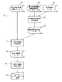
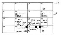
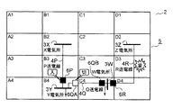
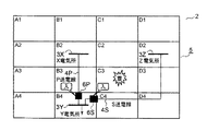
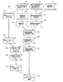
先ず第1の実施形態を図1乃至図3により説明する。図1は機能構成を示すブロック図であり、図2は通常時の監視区域の状況を示す図であり、図3は発雷時の監視区域の状況を示す図である。 First, a first embodiment will be described with reference to FIGS. FIG. 1 is a block diagram showing the functional configuration, FIG. 2 is a diagram showing the status of the monitoring area at the normal time, and FIG. 3 is a diagram showing the status of the monitoring area at the time of lightning.
図1乃至図3において、電力系統監視装置1は、予め複数に区画設定された監視区域2の区域A1,A2,…,A4,…,B1,B2,…,B4,…,C1,C2,…,C4,…,D1,D2,…,D4,…を監視し、特に区域内の発電所、変電所等の電気所3や送電線4などの電力系統設備が配置された雷監視区域5について監視するようになっている。雷監視区域5は、例えば監視区域2の区域B2,B3,B4,C4,D2,D3,D4となっており、区域B2には、X電気所3X、区域B4にY電気所3Y、区域C4にW電気所3W、区域D2にZ電気所3Zが設置されている。さらに、X電気所3XとY電気所3Yとは、区域B2,B3,B4を通るP送電線4Pによって結ばれており、Y電気所3YとW電気所3Wとは、区域B4,C4内を通るQ送電線4Qによって結ばれており、W電気所3WとZ電気所3Zとは、区域C4,D4,D3,D2を通るR送電線4Rによって結ばれている。
1 to 3, the power
そして、通常の運用時のY電気所3Yへの電力供給は、Z電気所3ZからR送電線4R、W電気所3W、Q送電線4Qを経由して行なわれ、W電気所3Wへの電力供給は、Z電気所3ZからR送電線4Rを使って行なわれるようになっており、Y電気所3YとW電気所3Wから図示しない需要側への電力供給が行われるようになっている。なお、6P,6QA,6QB,6Rは、各送電線4P,4Q,4Rに挿入された遮断器であり、P送電線4Pに挿入された遮断器6Pは「切」状態となっており、他の遮断器6QA,6QB,6Rは「入」状態となっている。
The electric power supply to the Y
また、電力系統監視装置1は、操作手順表作成手段7、操作手順表表示手段8、雷想定事故箇所判定手段9を備え、図示しない情報伝送装置を介して雷監視区域5である各区域B2,B3,B4,C4,D2,D3,D4内の各電気所3W,3X,3Y,3Zやこれら電気所3を結ぶ各送電線4P,4Q,4R等電力系統設備の種々の系統情報、例えば供給中の電力の電圧値、電流値やそれらの変動状況、遮断器6P,6QA,6QB,6Rの「入」、「切」の状態等の電力系統設備情報データ10と、発雷状況、発雷箇所等の発雷情報データ11を入手するようになっている。そして、雷想定事故箇所判定手段9では、入力した発雷情報データ11と、予め記憶している雷監視区域5内の電力系統設備についての電力系統雷監視区域データベース12とから雷想定事故箇所、すなわち雷による事故が想定される箇所を推定、判断して雷想定事故箇所データ13を操作手順表作成手段7に出力する。
In addition, the power
操作手順表作成手段7は、入力した雷想定事故箇所データ13と共に電力系統設備情報データ10と、予め記憶されたプログラムに従い雷想定事故箇所データ13と電力系統設備情報データ10とから、電力系統設備の事故により停電となる箇所が最小となるような電力系統の新たな構成を作成し、現構成を新たな構成へと構成変更を実行するための操作手順表データ14を作成し、操作手順表表示手段8に出力する。
The operation procedure table creating means 7 is configured to calculate the power system facility from the power system
この操作手順表作成手段7による電力系統の構成変更に関して、例えば図3に示すように監視区域2の区域D3で雷が発生した場合で説明すると、次のようになる。
The configuration change of the power system by the operation procedure table creation means 7 will be described as follows, for example, when lightning occurs in the area D3 of the
すなわち、区域D3で雷が発生したとの発雷情報データ11は、雷想定事故箇所判定手段9に入力される。それにより雷想定事故箇所判定手段9からは、気象状況や蓄積されている過去の事例等に基づく推定、判断がなされ、例えばR送電線4Rが被雷して送電事故の発生が想定されると判定し、雷想定事故箇所データ13が操作手順表作成手段7に出力される。
That is, the
操作手順表作成手段7は、雷想定事故箇所データ13に基づいて遮断器6Pを「入」状態に変えると同時に、遮断器6QAを「切」状態に変え、Y電気所3Yへの電力供給をX電気所3Xから行い、W電気所3Wへは引き続きZ電気所3ZからR送電線4Rに過負荷が生じないようにしながら電力供給を行う新たな電力系統の構成を作成する。さらに、現構成を新たな構成へと構成変更を実行するための操作手順表データ14を作成し、操作手順表表示手段8に出力する。
The operating procedure table creating means 7 changes the
そして、操作手順表データ14が入力した操作手順表表示手段8は、操作手順表データ14をもとに表示出力をマンマシンインターフェース装置15に出力し、マンマシンインターフェース装置15の表示部等によって操作者が、発雷箇所やそれに基づく電力系統の構成変更等を確認する。
Then, the operation procedure table display means 8 inputted with the operation
このように変更することで、R送電線4Rに落雷による送電事故が生じ、W電気所3Wへの電力供給を遮断するようにしても、Y電気所3Yへの電力供給が継続できることになる。なお、P送電線4Pの送電容量から可能であるならば、遮断器6Rを「切」状態に変え、遮断器6QA,6QBを「入」状態にしてW電気所3Wへの電力供給もX電気所3Xから行うようにしてもよい。
By changing in this way, even if a power transmission accident due to a lightning strike occurs on the R
以上の通り、上記の構成によれば、例えば監視区域2の区域D3で発雷の発雷情報データ11を入手した時点で、X電気所3XからP送電線4P経由でY電気所3Yへの電力供給を行うようにする、停電箇所を最小とする電力系統の新構成に変更するための操作手順表データ14が自動作成されることになるので、操作者の負担が減り、判断ミス等が生じる虞がなくなる。そして、電力系統を停電箇所が最小である構成にすることが、円滑且つ誤りなく行えることになる。
As described above, according to the above configuration, for example, at the time when the
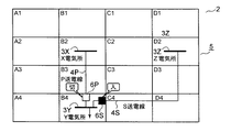
次に第2の実施形態を図4及び図5により、図1を参照し説明する。図4は通常時の監視区域の状況を示す図であり、図5は発雷時の監視区域の状況を示す図である。なお、本実施形態は第1の実施形態と監視区域に配置された電力系統設備の構成が異なるのみであるため、第1の実施形態と同一部分には同一符号を付して説明を省略し、第1の実施形態と異なる本実施形態の構成について説明する。 Next, a second embodiment will be described with reference to FIGS. 4 and 5 with reference to FIG. FIG. 4 is a diagram showing the status of the monitoring area during normal times, and FIG. 5 is a diagram showing the status of the monitoring area during lightning strikes. Since the present embodiment is different from the first embodiment only in the configuration of the power system equipment arranged in the monitoring area, the same parts as those in the first embodiment are denoted by the same reference numerals and description thereof is omitted. The configuration of this embodiment that is different from the first embodiment will be described.
図4及び図5において、電力系統監視装置1が監視する監視区域2の雷監視区域5は、例えばX電気所3X、Y電気所3Y、Z電気所3Zが配置された監視区域2の区域B2,B4,D2と、P送電線4P、S送電線4Sが架設された監視区域B3,C4,D3,D4となっており、P送電線4Pには遮断器6P、S送電線4Sには遮断器6Sが挿入されている。そして、第1の実施形態と同様構成の電力系統監視装置1による監視のもとに、通常の運用時のY電気所3Yへの電力供給は、図4に示すように遮断器6Pを「切」状態にし、遮断器6Sを「入」状態にしてS送電線4Sを使ってZ電気所4Zから行なわれる。
4 and 5, the
また、第1の実施形態と同様の構成の電力系統監視装置1は、その雷監視区域5の各電気所3X,3Y,3Z、各送電線4P,4S、各遮断器6P,6S等の電力系統設備に関する電力系統雷監視区域データベース12と発雷情報データ11をもとに、雷想定事故箇所判定手段9は、雷想定事故箇所データ13を操作手順表作成手段7に出力する。
In addition, the power
操作手順表作成手段7は、電力系統設備情報データ10と入力した雷想定事故箇所データ13をもとに、電力系統設備の事故等によって停電となる箇所がゼロとなるような電力系統の新たな構成を作成する。例えば図5に示すように監視区域2の区域C3で雷が発生したとすると、電力系統監視装置1では、区域C3で雷が発生したとの発雷情報データ11が、雷想定事故箇所判定手段9に入力される。
Based on the power system
それにより雷想定事故箇所判定手段9からは、気象状況や蓄積されている過去の事例等に基づく推定、判断がなされ、P送電線4PとS送電線4Sが現在は被雷していないが被雷する虞があると判定し、雷想定事故箇所データ13が出力される。出力された雷想定事故箇所データ13に基づいて操作手順表作成手段7は、遮断器6Sを「入」状態にしたまま遮断器6Pを「入」状態に変え、Y電気所3Yへの電力供給を、引き続きZ電気所3Zから行いながらX電気所3Xからも行う新たな電力系統の構成を作成する。さらに、現構成を新たな構成へと構成変更を実行するための操作手順表データ14を作成し、操作手順表表示手段8に出力する。
As a result, the lightning assumption accident location determination means 9 performs estimation and determination based on the weather conditions and accumulated past cases, and the
そして、操作手順表データ14が入力した操作手順表表示手段8は、操作手順表データ14をもとに表示出力をマンマシンインターフェース装置15に出力し、マンマシンインターフェース装置15の表示部等によって操作者が、発雷箇所やそれに基づく電力系統の構成変更等を確認する。
Then, the operation procedure table display means 8 inputted with the operation
このように変更することで、例えばS送電線4Sが被雷して事故が生じ、Z電気所3ZからY電気所3Yへの電力供給ができなくなっても、X電気所3Xからの電力供給が継続でき、停電することがない。
By changing in this way, for example, even if the
以上の通り、上記の構成によれば、例えば監視区域2の区域C3で発雷の発雷情報データ11を入手した時点で、X電気所3XからP送電線4P経由でY電気所3Yへの電力供給を行うようにする、停電箇所がゼロとなる電力系統の新構成に変更するための操作手順表データ14が自動作成されることになるので、第1の実施形態と同様に、操作者の負担が減り、判断ミス等が生じる虞がなくなる。そして、電力系統を停電箇所が無くなる構成にすることが、円滑且つ誤りなく行えることになる。
As described above, according to the above configuration, for example, when the
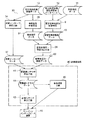
次に第3の実施形態を図6により、図2を参照し説明する。図6は機能構成を示すブロック図である。なお、本実施形態は第1の実施形態と機能構成の一部が異なるのみであるため、第1の実施形態と同一部分には同一符号を付して説明を省略し、第1の実施形態と異なる本実施形態の構成について説明する。 Next, a third embodiment will be described with reference to FIG. FIG. 6 is a block diagram showing a functional configuration. Note that this embodiment is different from the first embodiment only in part of the functional configuration, and therefore, the same parts as those in the first embodiment are denoted by the same reference numerals and description thereof is omitted. The configuration of the present embodiment, which is different from FIG.
図6において、電力系統監視装置16は、例えば監視区域2とその雷監視区域5内を監視するようになっている。また電力系統監視装置16は、操作手順表自動実行手段17を備えている点のみが第1の実施形態の電力系統監視装置1と異なっている。
In FIG. 6, the power
すなわち、電力系統監視装置16は、操作手順表作成手段7、操作手順表表示手段8、雷想定事故箇所判定手段9、操作手順表自動実行手段17を備え、例えば図2の雷監視区域5である各区域B2,B3,B4,C4,D2,D3,D4内の各電気所3W,3X,3Y,3Zやこれら電気所3を結ぶ各送電線4P,4Q,4R等電力系統設備の電力系統設備情報データ10と、発雷情報データ11を入手するようになっている。そして、雷想定事故箇所判定手段9では、入力した発雷情報データ11と電力系統雷監視区域データベース12とから雷想定事故箇所、すなわち雷による事故が想定される箇所を推定、判断して雷想定事故箇所データ13を操作手順表作成手段7に出力する。
That is, the electric power
操作手順表作成手段7は、雷想定事故箇所データ13と共に電力系統設備情報データ10が入力され、雷想定事故箇所データ13と電力系統設備情報データ10とから、電力系統設備の事故により停電となる箇所が最小となるような、あるいはゼロとなるような電力系統の新たな構成を作成し、現構成を新たな構成へと構成変更を実行するための操作手順表データ14を作成し、操作手順表表示手段8に出力する。同時に、雷監視区域5の電力系統設備の作動を操作手順表データ14に基づき自動操作するようプログラムされた構成の操作手順表自動実行手段17に出力する。
The operating procedure table creation means 7 receives the power system
電力系統の構成変更は、例えば区域D3で雷が発生した場合、雷想定事故箇所判定手段9が発雷情報データ11に基づいてR送電線4Rへの落雷により送電事故の発生が想定されると判定し、雷想定事故箇所データ13が操作手順表作成手段7に出力される。操作手順表作成手段7は、遮断器6Pを「入」状態に、遮断器6QAを「切」状態に変えて、電力供給をY電気所3YへはX電気所3Xから、W電気所3Wへは引き続きZ電気所3Zから行う新たな電力系統の構成を作成し、新たな構成へと構成変更するための操作手順表データ14を作成し、操作手順表表示手段8に出力する。同時に、操作手順表データ14を操作手順表自動実行手段17に出力する。
For example, when a lightning occurs in the area D3, it is assumed that a lightning accident is assumed by the lightning strike to the
そして、操作手順表表示手段8は、操作手順表データ14をもとに表示出力をマンマシンインターフェース装置15に出力し、マンマシンインターフェース装置15の表示部等によって操作者が、発雷箇所やそれに基づく電力系統の構成変更等を確認する。一方、操作手順表自動実行手段17は、予めプログラムされている雷監視区域5の電力系統設備の自動操作内容に従い、対象となる電力系統設備の遮断器6Pを「入」状態に、遮断器6QAを「切」状態に変える操作を実行し、発雷に対する対応処置が自動的に完了する。これにより、R送電線4Rに落雷事故が生じ、W電気所3Wへの電力供給を遮断するようにしても、Y電気所3Yへの電力供給が継続できることになる。
Then, the operation procedure table display means 8 outputs a display output to the man-
以上の通り、上記の構成によれば、例えば監視区域2の区域D3で発雷の発雷情報データ11を入手した時点で、X電気所3XからP送電線4P経由でY電気所3Yへの電力供給を行うようにする、停電箇所を最小とする電力系統の新構成に変更するための操作手順表データ14が自動作成され、また電力系統の新構成への構成変更が自動的に実行されることになるので、第1の実施形態と同様に、操作者の負担が減り、判断ミス等が生じる虞がなくなる。そして、電力系統を停電箇所が最小である構成にすることが、円滑且つ誤りなく行えることになる。
As described above, according to the above configuration, for example, at the time when the
次に第4の実施形態を図7により、図2を参照し説明する。図7は機能構成を示すブロック図である。なお、本実施形態は第3の実施形態と機能構成の一部が異なるのみであるため、第3の実施形態と同一部分には同一符号を付して説明を省略し、第1及び第3の実施形態と異なる本実施形態の構成について説明する。 Next, a fourth embodiment will be described with reference to FIG. FIG. 7 is a block diagram showing a functional configuration. Note that this embodiment is different from the third embodiment only in part of the functional configuration, and therefore, the same parts as those in the third embodiment are denoted by the same reference numerals, and the description thereof is omitted. The configuration of the present embodiment, which is different from the present embodiment, will be described.
図7において、電力系統監視装置18は、例えば監視区域2とその雷監視区域5内を監視するようになっている。また電力系統監視装置18は、操作手順表自動/手動切替手段19、操作手順表手動実行手段20を備えている点のみが第3の実施形態の電力系統監視装置16と異なっている。
In FIG. 7, the power
すなわち、電力系統監視装置18は、操作手順表作成手段7、操作手順表表示手段8、雷想定事故箇所判定手段9、操作手順表自動実行手段17、操作手順表手動実行手段19、操作手順表自動/手動切替手段20を備え、例えば図2の雷監視区域5である各区域B2,B3,B4,C4,D2,D3,D4内の各電気所3W,3X,3Y,3Zやこれら電気所3を結ぶ各送電線4P,4Q,4R等電力系統設備の電力系統設備情報データ10と、発雷情報データ11を入手するようになっている。そして、雷想定事故箇所判定手段9では、入力した発雷情報データ11と電力系統雷監視区域データベース12とから雷想定事故箇所、すなわち雷による事故が想定される箇所を推定、判断して雷想定事故箇所データ13を操作手順表作成手段7に出力する。
That is, the power
操作手順表作成手段7は、雷想定事故箇所データ13と共に電力系統設備情報データ10が入力され、雷想定事故箇所データ13と電力系統設備情報データ10とから、電力系統設備の事故により停電となる箇所が最小となるような、あるいはゼロとなるような電力系統の新たな構成を作成し、現構成を新たな構成へと構成変更を実行するための操作手順表データ14を作成し、操作手順表表示手段8に出力する。同時に、操作手順表自動実行手段17と操作手順表手動実行手段19に出力する。操作手順表自動実行手段17と操作手順表手動実行手段19とは、操作手順表自動/手動切替手段20により、いずれか一方を選択、切替えることができるようになっている。
The operating procedure table creation means 7 receives the power system
電力系統の構成変更は、例えば区域D3で雷が発生した場合、雷想定事故箇所判定手段9が発雷情報データ11に基づいてR送電線4Rへの落雷により送電事故の発生が想定されると判定し、雷想定事故箇所データ13が操作手順表作成手段7に出力される。操作手順表作成手段7は、遮断器6Pを「入」状態に、遮断器6QAを「切」状態に変えて、電力供給をY電気所3YへはX電気所3Xから、W電気所3Wへは引き続きZ電気所3Zから行う新たな電力系統の構成を作成し、新たな構成へと構成変更するための操作手順表データ14を作成し、操作手順表表示手段8に出力する。同時に、操作手順表データ14を操作手順表自動/手動切替手段20により、予め選択、切替えられている例えば操作手順表自動実行手段17に出力する。
For example, when a lightning occurs in the area D3, it is assumed that a lightning accident is assumed by the lightning strike to the
そして、操作手順表表示手段8は、操作手順表データ14をもとに表示出力をマンマシンインターフェース装置15に出力し、マンマシンインターフェース装置15の表示部等によって操作者が、発雷箇所やそれに基づく電力系統の構成変更等を確認する。また操作手順表自動実行手段17は、予めプログラムされている雷監視区域5の電力系統設備の自動操作内容に従い、対象となる電力系統設備の遮断器6Pを「入」状態に、遮断器6QAを「切」状態に変える操作を実行し、発雷に対する対応処置が自動的に完了する。これにより、R送電線4Rに落雷事故が生じ、W電気所3Wへの電力供給を遮断するようにしても、Y電気所3Yへの電力供給が継続できることになる。
Then, the operation procedure table display means 8 outputs a display output to the man-
また、操作手順表自動/手動切替手段20により、操作手順表手動実行手段19が選択されている場合には、操作者が操作手順表手動実行手段19を操作手順表データ14、操作手順表表示手段8により表示されたマンマシンインターフェース装置15の表示部等の表示内容に基づき、遮断器6Pを「入」状態に、遮断器6QAを「切」状態に変える操作を実行し、発雷に対する対応処置操作を実行する。
When the operation procedure table manual execution means 19 is selected by the operation procedure table automatic / manual switching means 20, the operator operates the operation procedure table manual execution means 19 with the operation
以上の通り、上記の構成によれば、例えば監視区域2の区域D3で発雷の発雷情報データ11を入手した時点で、X電気所3XからP送電線4P経由でY電気所3Yへの電力供給を行うようにする、停電箇所を最小とする電力系統の新構成に変更するための操作手順表データ14が自動作成され、また電力系統の新構成への構成変更が自動/手動のいずれかを選択して実行することができることになるので、第3の実施形態と同様の効果が得られると共に、より高度の系統運用の支援を行うことができる。
As described above, according to the above configuration, for example, at the time when the
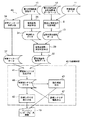
次に第5の実施形態を図8により、図2を参照し説明する。図8は機能構成を示すブロック図である。なお、本実施形態は第1の実施形態と機能構成の一部が異なるのみであるため、第1の実施形態と同一部分には同一符号を付して説明を省略し、第1の実施形態と異なる本実施形態の構成について説明する。 Next, a fifth embodiment will be described with reference to FIG. FIG. 8 is a block diagram showing a functional configuration. Note that this embodiment is different from the first embodiment only in part of the functional configuration, and therefore, the same parts as those in the first embodiment are denoted by the same reference numerals and description thereof is omitted. The configuration of the present embodiment, which is different from FIG.
図8において、電力系統監視装置21は、例えば監視区域2とその雷監視区域5内を監視するようになっている。また電力系統監視装置21は、操作手順表模擬実行手段22を備えている点のみが第1の実施形態の電力系統監視装置1と異なっている。
In FIG. 8, the power
すなわち、電力系統監視装置21は、操作手順表作成手段7、操作手順表表示手段8、雷想定事故箇所判定手段9、操作手順表模擬実行手段22を備え、例えば図2の雷監視区域5である各区域B2,B3,B4,C4,D2,D3,D4内の各電気所3W,3X,3Y,3Zやこれら電気所3を結ぶ各送電線4P,4Q,4R等電力系統設備の電力系統設備情報データ10と、発雷情報データ11を入手するようになっている。そして、雷想定事故箇所判定手段9では、入力した発雷情報データ11と電力系統雷監視区域データベース12とから雷想定事故箇所、すなわち雷による事故が想定される箇所を推定、判断して雷想定事故箇所データ13を操作手順表作成手段7に出力する。
That is, the power
操作手順表作成手段7は、雷想定事故箇所データ13と共に電力系統設備情報データ10が入力され、雷想定事故箇所データ13と電力系統設備情報データ10とから、電力系統設備の事故により停電となる箇所が最小となるような、あるいはゼロとなるような電力系統の新たな構成を作成し、現構成を新たな構成へと構成変更を実行するための操作手順表データ14を作成し、操作手順表表示手段8に出力する。同時に、操作手順表模擬実行手段22に出力する。
The operating procedure table creation means 7 receives the power system
電力系統の構成変更は、例えば区域D3で雷が発生した場合、雷想定事故箇所判定手段9が発雷情報データ11に基づいてR送電線4Rへの落雷により送電事故の発生が想定されると判定し、雷想定事故箇所データ13が操作手順表作成手段7に出力される。操作手順表作成手段7は、遮断器6Pを「入」状態に、遮断器6QAを「切」状態に変えて、電力供給をY電気所3YへはX電気所3Xから、W電気所3Wへは引き続きZ電気所3Zから行う新たな電力系統の構成を作成し、新たな構成へと構成変更するための操作手順表データ14を作成し、操作手順表表示手段8に出力する。同時に、操作手順表データ14を操作手順表模擬実行手段22に出力する。
For example, when a lightning occurs in the area D3, it is assumed that a lightning accident is assumed by the lightning strike to the
そして、操作手順表表示手段8は、操作手順表データ14をもとに表示出力をマンマシンインターフェース装置15に出力し、マンマシンインターフェース装置15の表示部等によって操作者が、発雷箇所やそれに基づく電力系統の構成変更等を確認することができるようになっている。
Then, the operation procedure table display means 8 outputs a display output to the man-
一方、操作手順表模擬実行手段22には、予め雷監視区域5の各電気所3W,3X,3Y,3Zやこれら電気所3を結ぶ各送電線4P,4Q,4R等電力系統設備の模擬操作がマンマシンインターフェース装置15の表示部等を使ってできるようにプログラムされている。このため、操作手順表模擬実行手段22に発雷情報データ11に基づく操作手順表データ14が入力されると、それに対応して構成変更を模擬実行する内容がマンマシンインターフェース装置15の表示部等に表示され、操作者が表示されたものを使って事前に模擬実行することができるようになっている。
On the other hand, in the operation procedure table simulation execution means 22, simulation operations of electric power system equipment such as the
以上の通り、上記の構成によれば、第1の実施形態と同様に、操作者の負担が減り、判断ミス等が生じる虞がなくなり、また、電力系統を停電箇所が最小である構成にすることが、円滑且つ誤りなく行えることになる。さらに、作成された操作手順表データ14にしたがって構成変更を模擬実行することができ、実操作等をする前に、操作手順表データ14に矛盾がないことを確認することができる。
As described above, according to the above-described configuration, similarly to the first embodiment, the burden on the operator is reduced, there is no possibility of making a determination error, and the power system is configured to have the smallest power outage location. Can be performed smoothly and without error. Furthermore, a configuration change can be simulated according to the created operation
次に第6の実施形態を図9により、図2を参照し説明する。図9は機能構成を示すブロック図である。なお、本実施形態は第1の実施形態と機能構成の一部が異なるのみであるため、第1の実施形態と同一部分には同一符号を付して説明を省略し、第1の実施形態と異なる本実施形態の構成について説明する。 Next, a sixth embodiment will be described with reference to FIG. FIG. 9 is a block diagram showing a functional configuration. Note that this embodiment is different from the first embodiment only in part of the functional configuration, and therefore, the same parts as those in the first embodiment are denoted by the same reference numerals and description thereof is omitted. The configuration of the present embodiment, which is different from FIG.
図9において、電力系統監視装置23は、例えば監視区域2とその雷監視区域5内を監視するようになっている。また電力系統監視装置23は、操作手順表訓練取込手段24、操作手順表訓練編集手段25を備えている点のみが第1の実施形態の電力系統監視装置1と異なっている。
In FIG. 9, the power
すなわち、電力系統監視装置23は、操作手順表作成手段7、操作手順表表示手段8、雷想定事故箇所判定手段9、操作手順表訓練取込手段24、操作手順表訓練編集手段25を備え、例えば図2の雷監視区域5である各区域B2,B3,B4,C4,D2,D3,D4内の各電気所3W,3X,3Y,3Zやこれら電気所3を結ぶ各送電線4P,4Q,4R等電力系統設備の電力系統設備情報データ10と、発雷情報データ11を入手するようになっている。そして、雷想定事故箇所判定手段9では、入力した発雷情報データ11と電力系統雷監視区域データベース12とから雷想定事故箇所、すなわち雷による事故が想定される箇所を推定、判断して雷想定事故箇所データ13を操作手順表作成手段7に出力する。
That is, the power
操作手順表作成手段7は、雷想定事故箇所データ13と共に電力系統設備情報データ10が入力され、雷想定事故箇所データ13と電力系統設備情報データ10とから、電力系統設備の事故により停電となる箇所が最小となるような、あるいはゼロとなるような電力系統の新たな構成を作成し、現構成を新たな構成へと構成変更を実行するための操作手順表データ14を作成し、操作手順表表示手段8に出力する。同時に、操作手順表訓練取込手段24に出力する。
The operating procedure table creation means 7 receives the power system
電力系統の構成変更は、例えば区域D3で雷が発生した場合、雷想定事故箇所判定手段9が発雷情報データ11に基づいてR送電線4Rへの落雷により送電事故の発生が想定されると判定し、雷想定事故箇所データ13が操作手順表作成手段7に出力される。操作手順表作成手段7は、遮断器6Pを「入」状態に、遮断器6QAを「切」状態に変えて、電力供給をY電気所3YへはX電気所3Xから、W電気所3Wへは引き続きZ電気所3Zから行う新たな電力系統の構成を作成し、新たな構成へと構成変更するための操作手順表データ14を作成し、操作手順表表示手段8に出力する。同時に、操作手順表データ14を操作手順表訓練取込手段24に出力する。
For example, when a lightning occurs in the area D3, it is assumed that a lightning accident is assumed by the lightning strike to the
そして、操作手順表表示手段8は、操作手順表データ14をもとに表示出力をマンマシンインターフェース装置15に出力し、マンマシンインターフェース装置15の表示部等によって操作者が、発雷箇所やそれに基づく電力系統の構成変更等を確認する。
Then, the operation procedure table display means 8 outputs a display output to the man-
一方、操作手順表訓練取込手段24では、取り込んだ操作手順表データ14を操作者が発雷時対応訓練を実施する際のデータとして取り込み、記憶し、訓練時に訓練操作手順表データ26として出力する。また、操作者の訓練を行う際には、訓練操作手順表データ26を操作手順表訓練編集手段25によって訓練内容に促した内容となるように編集し、例えばマンマシンインターフェース装置15の表示部等を使い、雷監視区域5の各電気所3W,3X,3Y,3Zやこれら電気所3を結ぶ各送電線4P,4Q,4R等電力系統設備を模擬操作する訓練を行えるようになっている。
On the other hand, the operation procedure table training capturing means 24 captures and stores the captured operation
以上の通り、上記の構成によれば、第1の実施形態と同様の効果が得られると共に、実データあるいは編集したデータを使っての操作者の訓練を行うことができ、操作者の技能を向上させることができる。 As described above, according to the above configuration, the same effects as those of the first embodiment can be obtained, and operator training using actual data or edited data can be performed. Can be improved.
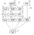
次に第7の実施形態を図10により、図2を参照し説明する。図10は機能構成を示すブロック図である。なお、第1の実施形態と同一部分には同一符号を付して説明を省略し、第1の実施形態と異なる本実施形態の構成について説明する。 Next, a seventh embodiment will be described with reference to FIG. FIG. 10 is a block diagram showing a functional configuration. In addition, the same code | symbol is attached | subjected to the same part as 1st Embodiment, description is abbreviate | omitted, and the structure of this embodiment different from 1st Embodiment is demonstrated.
図10において、電力系統監視装置27は、例えば監視区域2とその雷監視区域5内を監視するようになっている。また電力系統監視装置27は、雷想定事故箇所判定手段9、事故箇所判定手段28、雷事故箇所・原因判定手段29、雷事故箇所・原因表示手段30を備え、例えば図2の雷監視区域5である各区域B2,B3,B4,C4,D2,D3,D4内の各電気所3W,3X,3Y,3Zやこれら電気所3を結ぶ各送電線4P,4Q,4R等電力系統設備の電力系統設備情報データ10と、発雷情報データ11を入手するようになっている。
In FIG. 10, the power
そして、雷想定事故箇所判定手段9では、入力した発雷情報データ11と電力系統雷監視区域データベース12とから雷想定事故箇所、すなわち雷による事故が想定される箇所を推定、判断して雷想定事故箇所データ13を雷事故箇所・原因判定手段29に出力する。また事故箇所判定手段28では、入力した電力系統設備情報データ10から雷監視区域5内の電力系統設備の事故箇所を見出し、事故箇所データ31を雷事故箇所・原因判定手段29に出力する。
The lightning assumption accident location determination means 9 estimates and determines a lightning assumption accident location, that is, a location where a lightning accident is assumed, from the input
雷事故箇所・原因判定手段29は、入力された雷想定事故箇所データ13と事故箇所データ31とから、雷監視区域5内の電力系統設備に発生している事故が発雷に基づくものであるか否かの判定を行い、判定結果の雷事故箇所・原因データ32を雷事故箇所・原因表示手段30に出力する。雷事故箇所・原因データ32が入力した雷事故箇所・原因表示手段30は、雷事故箇所・原因データ32をもとに表示出力をマンマシンインターフェース装置15に出力する。そして、マンマシンインターフェース装置15の表示部等には、発雷に基づいて電力系統設備に事故が発生しているか否か、あるいは電力系統設備の事故が発雷によるものか否かの表示がなされる。
The lightning accident location / cause determination means 29 is based on the occurrence of the lightning accident occurring in the power system facility in the
これにより操作者は、発雷による事故の有無、事故が発雷に由来するものであるか確認することができ、また系統運用時の判断の支援を受けられ、操作に対する負担が軽減されることになる。 As a result, the operator can confirm the presence or absence of an accident due to a lightning strike and whether the accident is caused by a lightning strike, and can receive judgment support during system operation, reducing the burden on operation. become.
次に第8の実施形態を図11により、図2を参照し説明する。図11は機能構成を示すブロック図である。なお、本実施形態は第7の実施形態と機能構成の一部が異なるのみであるため、第7の実施形態と同一部分には同一符号を付して説明を省略し、第7の実施形態と異なる本実施形態の構成について説明する。 Next, an eighth embodiment will be described with reference to FIG. FIG. 11 is a block diagram showing a functional configuration. Note that this embodiment is different from the seventh embodiment only in part of the functional configuration, and therefore, the same parts as those in the seventh embodiment are denoted by the same reference numerals and description thereof is omitted. The configuration of the present embodiment, which is different from FIG.
図11において、電力系統監視装置33は、例えば監視区域2とその雷監視区域5内を監視するようになっている。また電力系統監視装置33は、雷想定事故箇所判定手段9、事故箇所判定手段28、雷事故箇所・原因判定手段29、雷事故箇所・原因表示手段30、状変メッセージ作成手段34、雷組合せ状変メッセージ作成手段35、状変メッセージ表示手段36を備え、例えば図2の雷監視区域5の各電気所3W,3X,3Y,3Zや各送電線4P,4Q,4R等電力系統設備の電力系統設備情報データ10と、発雷情報データ11を入手するようになっている。そして、雷想定事故箇所判定手段9では、発雷情報データ11と電力系統雷監視区域データベース12とから雷想定事故箇所データ13を雷事故箇所・原因判定手段29に出力する。また事故箇所判定手段28では、電力系統設備情報データ10から雷監視区域5での事故箇所データ31を雷事故箇所・原因判定手段29に出力する。
In FIG. 11, the power
雷事故箇所・原因判定手段29は、入力した雷想定事故箇所データ13と事故箇所データ31とから、雷監視区域5内の電力系統設備に発生している事故が発雷に基づくものであるか否かの判定を行い、判定結果の雷事故箇所・原因データ32を雷事故箇所・原因表示手段30と雷組合せ状変メッセージ作成手段35に出力する。雷事故箇所・原因データ32が入力した雷事故箇所・原因表示手段30は、雷事故箇所・原因データ32をもとに表示出力をマンマシンインターフェース装置15に出力する。そして、マンマシンインターフェース装置15の表示部等には、発雷に基づいて電力系統設備に事故が発生しているか否か、あるいは電力系統設備の事故が発雷によるものか否かの表示がなされる。
The lightning accident location / cause determination means 29 determines whether the accident occurring in the power system facility in the
また、状変メッセージ作成手段34については、入力した電力系統設備情報データ10を加工、編集等して電力系統や各設備の状態変化情報である状態変化メッセージ(状変メッセージ)を作成し、状変メッセージデータ37を雷組合せ状変メッセージ作成手段35に出力する。
The status change message creating means 34 processes and edits the input power system
そして、雷事故箇所・原因データ32と状変メッセージデータ37とが入力した雷組合せ状変メッセージ作成手段35では、両データ32,37を参照して、発雷に基づく電力系統設備の事故等に関わる情報と、電力系統や各設備の状態変化情報とを組み合わせた雷組合せ状変メッセージデータ38を状変メッセージ表示手段に出力する。状変メッセージ表示手段は、入力した雷組合せ状変メッセージデータ38をもとに表示出力をマンマシンインターフェース装置15に出力する。それにより、マンマシンインターフェース装置15の表示部等には、発雷に基づく電力系統設備の事故等と、電力系統や各設備の状態変化の状況が同時表示される。
Then, the lightning combination state change message creating means 35 inputted with the lightning accident location /
これにより操作者は、発雷による事故の有無、事故が発雷に由来するものであるか確認や、電力系統や各設備の状態変化の様子を一度に把握することができ、系統運用時の判断の支援を受けられ、操作に対する負担が軽減されることになる。 This allows the operator to check whether there is an accident due to a lightning strike, whether the accident is caused by a lightning strike, and to understand the state of the power system and the status of each facility at a time. The support of the judgment is received, and the burden on the operation is reduced.
次に第9の実施形態を図12により、図2を参照し説明する。図12は機能構成を示すブロック図である。なお、本実施形態は第8の実施形態と機能構成の一部が異なるのみであるため、第8の実施形態と同一部分には同一符号を付して説明を省略し、第8の実施形態と異なる本実施形態の構成について説明する。 Next, a ninth embodiment will be described with reference to FIG. FIG. 12 is a block diagram showing a functional configuration. Note that this embodiment differs from the eighth embodiment only in part of the functional configuration, and therefore, the same parts as those in the eighth embodiment are denoted by the same reference numerals and description thereof is omitted, and the eighth embodiment is omitted. The configuration of the present embodiment, which is different from FIG.
図12において、電力系統監視装置39は、例えば監視区域2とその雷監視区域5内を監視するようになっている。また電力系統監視装置39は、雷想定事故箇所判定手段9、事故箇所判定手段28、雷事故箇所・原因判定手段29、状変メッセージ作成手段34と、訓練機能部40を構成する雷訓練シナリオ取込手段41、訓練シナリオ表示手段42、系統模擬手段43を備え、例えば図2の雷監視区域5の各電気所3W,3X,3Y,3Zや各送電線4P,4Q,4R等電力系統設備の電力系統設備情報データ10と、発雷情報データ11を入手するようになっている。
In FIG. 12, the power
そして、雷想定事故箇所判定手段9では、発雷情報データ11と電力系統雷監視区域データベース12とから雷想定事故箇所データ13を雷事故箇所・原因判定手段29に出力する。また事故箇所判定手段28では、電力系統設備情報データ10から雷監視区域5での事故箇所データ31を雷事故箇所・原因判定手段29に出力する。雷想定事故箇所データ13と事故箇所データ31が入力した雷事故箇所・原因判定手段29は、両データ13,31とから、雷監視区域5内の電力系統設備に発生している事故が発雷に基づくものであるか否かの判定を行い、判定結果の雷事故箇所・原因データ32を訓練機能部40の雷訓練シナリオ取込手段41に出力する。
Then, the lightning assumption accident location determination means 9 outputs the lightning assumption
一方、状変メッセージ作成手段34については、入力した電力系統設備情報データ10を加工、編集等して電力系統や各設備の状態変化情報である状変メッセージを作成し、状変メッセージデータ37を訓練機能部40の雷訓練シナリオ取込手段41に出力する。また、雷事故箇所・原因データ32と状変メッセージデータ37が入力した雷訓練シナリオ取込手段41は、両データ32,37を参照し、雷による状変メッセージを雷訓練シナリオデータ44として保存すると共に、訓練シナリオ表示手段42と系統模擬手段43に出力する。
On the other hand, the state change message creating means 34 processes and edits the input power system
そして、訓練シナリオ表示手段42は、雷訓練シナリオデータ44をもとに表示出力をマンマシンインターフェース装置15に出力し、マンマシンインターフェース装置15では、表示部等に雷訓練シナリオデータ44の表示を行うことで、雷訓練シナリオデータ44の内容を操作者が確認することができるようになっている。また系統模擬手段43は、入力した雷訓練シナリオデータ44による系統運用操作の訓練が、マンマシンインターフェース装置15の表示部等と連携させてできるよう構成されている。
And the training scenario display means 42 outputs a display output to the man-
このように、雷を原因とする状変メッセージデータ37を雷訓練シナリオデータ44として取り込めるので、実際の発雷時の状況に沿った訓練シナリオにより、操作者の発雷時の訓練を行うことができるので、操作者の技能向上を図ることができ、実操作の際の操作者による差が少なくなって系統運用をより安定したものとすることができる。
As described above, since the state
次に第10の実施形態を図13により、図2を参照し説明する。図13は機能構成を示すブロック図である。なお、本実施形態は第9の実施形態と機能構成の一部が異なるのみであるため、第9の実施形態と同一部分には同一符号を付して説明を省略し、第8の実施形態と異なる本実施形態の構成について説明する。 Next, a tenth embodiment will be described with reference to FIG. FIG. 13 is a block diagram showing a functional configuration. Note that this embodiment differs from the ninth embodiment only in part of the functional configuration, and thus the same parts as those in the ninth embodiment are denoted by the same reference numerals and description thereof is omitted. The configuration of the present embodiment, which is different from FIG.
図13において、電力系統監視装置45は、例えば監視区域2とその雷監視区域5内を監視するようになっている。また電力系統監視装置45は、雷想定事故箇所判定手段9、事故箇所判定手段28、雷事故箇所・原因判定手段29、状変メッセージ作成手段34と、訓練機能部46を構成する雷訓練シナリオ取込手段41、訓練シナリオ表示手段42、系統模擬手段43、訓練シナリオ編集手段47を備え、例えば図2の雷監視区域5の各電気所3W,3X,3Y,3Zや各送電線4P,4Q,4R等電力系統設備の電力系統設備情報データ10と、発雷情報データ11を入手するようになっている。
In FIG. 13, the power
そして、雷想定事故箇所判定手段9では、発雷情報データ11と電力系統雷監視区域データベース12とから雷想定事故箇所データ13を雷事故箇所・原因判定手段29に出力する。また事故箇所判定手段28では、電力系統設備情報データ10から雷監視区域5での事故箇所データ31を雷事故箇所・原因判定手段29に出力する。雷想定事故箇所データ13と事故箇所データ31が入力した雷事故箇所・原因判定手段29は、両データ13,31とから、雷監視区域5内の電力系統設備に発生している事故が発雷に基づくものであるか否かの判定を行い、判定結果の雷事故箇所・原因データ32を訓練機能部46の雷訓練シナリオ取込手段41に出力する。
Then, the lightning assumption accident location determination means 9 outputs the lightning assumption
一方、状変メッセージ作成手段34については、入力した電力系統設備情報データ10を加工、編集等して電力系統や各設備の状態変化情報である状変メッセージを作成し、状変メッセージデータ37を訓練機能部46の雷訓練シナリオ取込手段41に出力する。また、雷事故箇所・原因データ32と状変メッセージデータ37が入力した雷訓練シナリオ取込手段41は、両データ32,37を参照し、雷による状変メッセージを雷訓練シナリオデータ44として保存すると共に、訓練シナリオ表示手段42と系統模擬手段43に出力する。
On the other hand, the state change message creating means 34 processes and edits the input power system
そして、訓練シナリオ表示手段42は、雷訓練シナリオデータ44をもとに表示出力をマンマシンインターフェース装置15に出力し、マンマシンインターフェース装置15では、表示部等に雷訓練シナリオデータ44の表示を行うことで、雷訓練シナリオデータ44の内容を操作者が確認することができるようになっている。また系統模擬手段43は、入力した雷訓練シナリオデータ44による系統運用操作の訓練が、マンマシンインターフェース装置15の表示部等と連携させてできるよう構成されている。
And the training scenario display means 42 outputs a display output to the man-
さらに、訓練機能部46に備えられた訓練シナリオ編集手段47は、雷訓練シナリオデータ44を編集できるように構成されており、雷訓練シナリオ取込手段41に保存されている、例えば複数の雷訓練シナリオデータ44をそれぞれ編集し、組み合わせる等することによって、連続して発生する雷を模擬したより実際の状況に近い訓練シナリオを作ることができる。
Furthermore, the training scenario editing means 47 provided in the training function unit 46 is configured to be able to edit the lightning
このように、雷を原因とする状変メッセージデータ37を雷訓練シナリオデータ44として取り込めるので、第9の実施形態と同様、実際の発雷時の状況、さらに雷が連続して発生する状況に沿ったより高度の訓練シナリオにより、操作者の発雷時の訓練を行うことができるので、操作者の技能向上を図ることができ、実操作の際の操作者による差が少なくなって系統運用をより安定したものとすることができる。
As described above, since the state
1…電力系統監視装置
2…監視区域
5…雷監視区域
7…操作手順表作成手段
8…操作手順表表示手段
9…雷想定事故箇所判定手段
10…電力系統設備情報データ
11…発雷情報データ
12…電力系統設備雷監視区域データベース
13…雷想定事故箇所データ
14…操作手順表データ
15…マンマシンインターフェース装置
DESCRIPTION OF
Claims (9)
前記発雷情報データと前記電力系統の雷監視区域データベースを参照し、雷想定事故箇所を判定する雷想定事故箇所判定手段と、
前記雷想定事故箇所判定手段で判定された雷想定事故箇所データと前記電力系統設備情報データを参照し、電力系統設備の事故により停電となる箇所が最小、またはゼロとなるような電力系統の構成変更を実行するための操作手順表データを作成する操作手順表作成手段と、
前記操作手順表データをマンマシンインターフェース装置へ通知する操作手順表表示手段を有することを特徴とする電力系統監視装置。 A power system monitoring device configured to monitor power system by obtaining power system facility information data and lightning information data through an information transmission device,
With reference to the lightning information data and the lightning monitoring area database of the power system, a lightning assumption accident location determination means for determining a lightning assumption accident location,
A power system configuration in which a lightning accident caused by a power system facility accident is minimized or zero with reference to the lightning assumed accident location data and the power system facility information data determined by the lightning expected accident location determination means. An operation procedure table creation means for creating operation procedure table data for executing the change;
An electric power system monitoring device comprising an operation procedure table display means for notifying the man-machine interface device of the operation procedure table data.
前記発雷情報データと前記電力系統の雷監視区域データベースを参照し、雷想定事故箇所を判定する雷想定事故箇所判定手段と、
前記電力系統設備情報データから事故箇所を判定する事故箇所判定手段と、
前記事故箇所判定手段で判定された事故箇所データと前記雷想定事故箇所判定手段で判定された雷想定事故箇所データを参照し、雷による事故箇所を判定する雷事故箇所・原因判定手段と、
前記雷事故箇所・原因判定手段判定された雷事故箇所・原因判定データをマンマシンインターフェース装置へ通知する雷事故箇所・原因表示手段
を有することを特徴とする電力系統監視装置。 A power system monitoring device configured to monitor power system by obtaining power system facility information data and lightning information data through an information transmission device,
With reference to the lightning information data and the lightning monitoring area database of the power system, a lightning assumption accident location determination means for determining a lightning assumption accident location,
Accident location determination means for determining an accident location from the power system facility information data,
A lightning accident location / cause determination means for determining an accident location caused by lightning with reference to the accident location data determined by the accident location determination means and the lightning assumption accident location data determined by the lightning assumption accident location determination means,
A power system monitoring apparatus comprising: a lightning accident location / cause display means for notifying the man-machine interface device of the lightning accident location / cause determination data determined by the lightning accident location / cause determination means.
前記発雷情報データと前記電力系統の雷監視区域データベースを参照し、雷想定事故箇所を判定する雷想定事故箇所判定手段と、
前記電力系統設備情報データから事故箇所を判定する事故箇所判定手段と、
前記事故箇所判定手段で判定された事故箇所データと前記雷想定事故箇所判定手段で判定された雷想定事故箇所データを参照し、雷による事故箇所を判定する雷事故箇所・原因判定手段と、
前記電力系統設備情報データから状変メッセージデータを作成する状変メッセージ作成手段と、
前記状変メッセージデータと前記雷事故箇所・原因データを参照し、雷による状変メッセージを雷訓練シナリオデータとして取り込む雷訓練シナリオ取込手段と、
前記雷訓練シナリオデータをマンマシンインターフェース装置で確認することを可能とする訓練シナリオ表示手段と、
前記雷訓練シナリオデータを実行し、前記マンマシンインターフェース装置で確認することを可能とする系統模擬手段を有することを特徴とする電力系統監視装置。 A power system monitoring device configured to monitor power system by obtaining power system facility information data and lightning information data through an information transmission device,
With reference to the lightning information data and the lightning monitoring area database of the power system, a lightning assumption accident location determination means for determining a lightning assumption accident location,
Accident location determination means for determining an accident location from the power system facility information data,
A lightning accident location / cause determination means for determining an accident location caused by lightning with reference to the accident location data determined by the accident location determination means and the lightning assumption accident location data determined by the lightning assumption accident location determination means,
State change message creating means for creating state change message data from the power system facility information data,
Lightning training scenario capturing means for referring to the state change message data and the lightning accident location / cause data, and for capturing a state change message due to lightning as lightning training scenario data;
Training scenario display means that makes it possible to confirm the lightning training scenario data with a man-machine interface device;
A power system monitoring apparatus comprising system simulation means for executing the lightning training scenario data and allowing confirmation by the man-machine interface apparatus.
Priority Applications (1)
| Application Number | Priority Date | Filing Date | Title |
|---|---|---|---|
| JP2008313860A JP2010141980A (en) | 2008-12-10 | 2008-12-10 | Electric power system monitor |
Applications Claiming Priority (1)
| Application Number | Priority Date | Filing Date | Title |
|---|---|---|---|
| JP2008313860A JP2010141980A (en) | 2008-12-10 | 2008-12-10 | Electric power system monitor |
Publications (1)
| Publication Number | Publication Date |
|---|---|
| JP2010141980A true JP2010141980A (en) | 2010-06-24 |
Family
ID=42351600
Family Applications (1)
| Application Number | Title | Priority Date | Filing Date |
|---|---|---|---|
| JP2008313860A Withdrawn JP2010141980A (en) | 2008-12-10 | 2008-12-10 | Electric power system monitor |
Country Status (1)
| Country | Link |
|---|---|
| JP (1) | JP2010141980A (en) |
Cited By (1)
| Publication number | Priority date | Publication date | Assignee | Title |
|---|---|---|---|---|
| JP2017184348A (en) * | 2016-03-29 | 2017-10-05 | 株式会社日立製作所 | Power system operation support device and method |
-
2008
- 2008-12-10 JP JP2008313860A patent/JP2010141980A/en not_active Withdrawn
Cited By (1)
| Publication number | Priority date | Publication date | Assignee | Title |
|---|---|---|---|---|
| JP2017184348A (en) * | 2016-03-29 | 2017-10-05 | 株式会社日立製作所 | Power system operation support device and method |
Similar Documents
| Publication | Publication Date | Title |
|---|---|---|
| KR102035351B1 (en) | Electric installation maintenance method and device | |
| CN107607833A (en) | A kind of pocket intelligent distribution type feeder automation test system | |
| EP2887340A1 (en) | Method of playing operation records of energy management system | |
| CN110086251A (en) | A kind of monitoring method and system improving electric grid operating safety | |
| CN112256922A (en) | A method and system for rapid identification of power failure | |
| KR101611048B1 (en) | system and method for training virtual fault of electric power system | |
| KR101505003B1 (en) | Reporting system through analysing operation of the protection relay | |
| CN202917090U (en) | Dynamic simulation substation sand table device | |
| JP2008178172A (en) | Supervisory control system for two or more electric stations | |
| CN102880172A (en) | Real-time control strategy checking method of safety stability control device | |
| JP2010124548A (en) | Power plant monitoring controller | |
| JP7253456B2 (en) | Abnormal response training method for power receiving equipment | |
| KR20090096101A (en) | System and method for preventing circuit breaker's wrong control using set theory | |
| JP2009273245A (en) | Power system monitor control system | |
| JP2010141980A (en) | Electric power system monitor | |
| JP2010273457A (en) | Wide-area distributed power system monitoring and control system | |
| JP5267839B2 (en) | Distant monitoring and control device simulation device and power system monitoring and control system | |
| KR100863672B1 (en) | Distribution automation education system and its driving method | |
| JP3392718B2 (en) | Simulator | |
| CN115549293A (en) | Multi-user online cooperative disposal system and method for grid-provincial power grid faults | |
| CN115798281A (en) | Relay Protection Practical Operation System Based on VR Visualization and Its Virtual Debugging Method | |
| JP5118439B2 (en) | Method for determining outage equipment in power system | |
| JP5235544B2 (en) | Accident recovery support system | |
| KR102005231B1 (en) | Rapid cruising fault analysis system for electrical equipment | |
| JP2736133B2 (en) | Power system training simulator |
Legal Events
| Date | Code | Title | Description |
|---|---|---|---|
| RD04 | Notification of resignation of power of attorney |
Free format text: JAPANESE INTERMEDIATE CODE: A7424 Effective date: 20110421 |
|
| A300 | Withdrawal of application because of no request for examination |
Free format text: JAPANESE INTERMEDIATE CODE: A300 Effective date: 20120306 |