JP2010141922A - System and method for converting wavelet and computer program product - Google Patents
System and method for converting wavelet and computer program product Download PDFInfo
- Publication number
- JP2010141922A JP2010141922A JP2010036657A JP2010036657A JP2010141922A JP 2010141922 A JP2010141922 A JP 2010141922A JP 2010036657 A JP2010036657 A JP 2010036657A JP 2010036657 A JP2010036657 A JP 2010036657A JP 2010141922 A JP2010141922 A JP 2010141922A
- Authority
- JP
- Japan
- Prior art keywords
- data
- wavelet
- format
- filter
- single device
- Prior art date
- Legal status (The legal status is an assumption and is not a legal conclusion. Google has not performed a legal analysis and makes no representation as to the accuracy of the status listed.)
- Pending
Links
Images


Classifications
-
- H—ELECTRICITY
- H04—ELECTRIC COMMUNICATION TECHNIQUE
- H04N—PICTORIAL COMMUNICATION, e.g. TELEVISION
- H04N19/00—Methods or arrangements for coding, decoding, compressing or decompressing digital video signals
- H04N19/40—Methods or arrangements for coding, decoding, compressing or decompressing digital video signals using video transcoding, i.e. partial or full decoding of a coded input stream followed by re-encoding of the decoded output stream
-
- H—ELECTRICITY
- H04—ELECTRIC COMMUNICATION TECHNIQUE
- H04N—PICTORIAL COMMUNICATION, e.g. TELEVISION
- H04N19/00—Methods or arrangements for coding, decoding, compressing or decompressing digital video signals
- H04N19/42—Methods or arrangements for coding, decoding, compressing or decompressing digital video signals characterised by implementation details or hardware specially adapted for video compression or decompression, e.g. dedicated software implementation
- H04N19/436—Methods or arrangements for coding, decoding, compressing or decompressing digital video signals characterised by implementation details or hardware specially adapted for video compression or decompression, e.g. dedicated software implementation using parallelised computational arrangements
-
- H—ELECTRICITY
- H04—ELECTRIC COMMUNICATION TECHNIQUE
- H04N—PICTORIAL COMMUNICATION, e.g. TELEVISION
- H04N19/00—Methods or arrangements for coding, decoding, compressing or decompressing digital video signals
- H04N19/60—Methods or arrangements for coding, decoding, compressing or decompressing digital video signals using transform coding
- H04N19/61—Methods or arrangements for coding, decoding, compressing or decompressing digital video signals using transform coding in combination with predictive coding
-
- H—ELECTRICITY
- H04—ELECTRIC COMMUNICATION TECHNIQUE
- H04N—PICTORIAL COMMUNICATION, e.g. TELEVISION
- H04N19/00—Methods or arrangements for coding, decoding, compressing or decompressing digital video signals
- H04N19/60—Methods or arrangements for coding, decoding, compressing or decompressing digital video signals using transform coding
- H04N19/62—Methods or arrangements for coding, decoding, compressing or decompressing digital video signals using transform coding by frequency transforming in three dimensions [3D]
-
- H—ELECTRICITY
- H04—ELECTRIC COMMUNICATION TECHNIQUE
- H04N—PICTORIAL COMMUNICATION, e.g. TELEVISION
- H04N19/00—Methods or arrangements for coding, decoding, compressing or decompressing digital video signals
- H04N19/60—Methods or arrangements for coding, decoding, compressing or decompressing digital video signals using transform coding
- H04N19/63—Methods or arrangements for coding, decoding, compressing or decompressing digital video signals using transform coding using sub-band based transform, e.g. wavelets
- H04N19/635—Methods or arrangements for coding, decoding, compressing or decompressing digital video signals using transform coding using sub-band based transform, e.g. wavelets characterised by filter definition or implementation details
Landscapes
- Engineering & Computer Science (AREA)
- Multimedia (AREA)
- Signal Processing (AREA)
- Computing Systems (AREA)
- Theoretical Computer Science (AREA)
- Compression Or Coding Systems Of Tv Signals (AREA)
- Compression, Expansion, Code Conversion, And Decoders (AREA)
- Compression Of Band Width Or Redundancy In Fax (AREA)
Abstract
Description
(発明の分野)
本発明はデータ圧縮に関するものであり、特に、ウェーブレットを利用したデータ圧縮に関するものである。
(Field of Invention)
The present invention relates to data compression, and more particularly, to data compression using wavelets.
(発明の背景)
ビデオ「コーデック」(圧縮/伸長器)は、画質、プロセッサについての要求(例えば、コスト/電力消費)、及び圧縮比(即ち生成されるデータレート)を均衡させることによってデータ通信ストリームに要求されるデータレートを低減するために用いられる。現在利用可能な圧縮方法は、異なる範囲のトレードオフ(得失)をもたらし、そして、複数のコーデックのプロファイル(形)を生み出し、各プロファイルは、特定用途における必要事項を満たすべく最適化されている。
(Background of the Invention)
A video “codec” (compressor / decompressor) is required for a data communication stream by balancing image quality, processor requirements (eg, cost / power consumption), and compression ratio (ie, data rate generated). Used to reduce data rate. Currently available compression methods provide different ranges of trade-offs and produce multiple codec profiles, each profile being optimized to meet specific application requirements.
図1に、従来技術の、現在利用可能な種々の圧縮アルゴリズム間のトレードオフの例100を示す。図に示すように、こうした圧縮アルゴリズムは、ウェーブレットベースのコーデック102、及び種々のMPEGビデオ配信プロファイルを含むDCT(Discrete Cosine Transform:離散コサイン変換)ベースのコーデック104を含む。
FIG. 1 shows an example 100 of trade-offs between various compression algorithms currently available in the prior art. As shown, such compression algorithms include a wavelet-based
2D及び3Dのウェーブレットは、DCTベースのコーデック・アルゴリズムの現在の代替法である。ウェーブレットは、その良好な画質及び自在(フレキシブル)な圧縮比によって、大いに注目されてきて、ウェーブレットアルゴリズムをJPEG−2000静止画規格に採用することを、JPEG委員会に促してきた。不都合なことに、大部分のウェーブレットの実現は非常に複雑なアルゴリズムを用い、代替法であるDCTに比べて膨大な処理パワー(力)を必要とする。これに加えて、ウェーブレットは時間圧縮にとって独特の挑戦をもたらし、3Dウェーブレットを特に困難にしている。 2D and 3D wavelets are current alternatives to DCT-based codec algorithms. Wavelets have received much attention due to their good image quality and flexible compression ratio, and have urged the JPEG Committee to adopt the wavelet algorithm in the JPEG-2000 still image standard. Unfortunately, most wavelet implementations use very complex algorithms and require enormous processing power compared to the alternative DCT. In addition, wavelets pose unique challenges for time compression, making 3D wavelets particularly difficult.
これらの理由により、ウェーブレットは、MPEGのように大量に用いられる工業規格のコーデックとコストで競り勝つ利点をもたらすことが決してなく、従って、すき間的(ニッチ)な用途に採用されるに過ぎなかった。従って、3つの大きな市場部分に焦点を合わせて低電力及び低コスト用に最適化した、商業的に生き残れる3Dウェーブレットを実現する必要がある。 For these reasons, wavelets have never offered a competitive advantage in cost with industrial standard codecs, such as MPEG, and have therefore only been adopted for niche applications. Therefore, there is a need to realize a commercially viable 3D wavelet that focuses on three large market segments and is optimized for low power and low cost.
例えば、小型ビデオカメラがより広く用いられ、ビデオカメラの信号をディジタルで扱うことの利点は明白である。例えば、一部の国におけるセルラー(移動)電話市場の最も急速な成長は、画像及びビデオクリップの機能を有する電話機によるものである。大部分のディジタル・スチル(静止画)カメラは、ビデオクリップ機能を有する。移動無線電話機(ハンドセット)の市場では、これらの静止画及び短いビデオクリップの伝送は、装置のバッテリの能力をより一層必要とする。既存のビデオ符号化規格及びディジタル信号プロセッサは、バッテリにより一層の負担をかける。 For example, small video cameras are more widely used, and the advantages of digitally handling video camera signals are obvious. For example, the fastest growth in the cellular (mobile) phone market in some countries is due to phones with image and video clip capabilities. Most digital still cameras have a video clip function. In the mobile radiotelephone (handset) market, the transmission of these still images and short video clips requires even more device battery capacity. Existing video coding standards and digital signal processors place an additional burden on the battery.
他の新たな用途は、視聴者が、生のTV(テレビ)放送の一時停止及びタイムシフト(時間をずらす)プログラミングができるパーソナル・ビデオレコーダ(PVR:個人用ディジタル録画編集機)である。これらの装置は、ディジタル・ハードディスク記憶装置を用いてビデオを記録し、ケーブルからのアナログビデオのビデオ圧縮を必要とする。こうした特徴を、ピクチャ−イン−ピクチャ(子画面、二画面)、視聴しながらの記録として提供するために、これらの装置は複数のビデオ圧縮エンコーダ(符号化器)を必要とする。 Another new application is a personal video recorder (PVR) that allows viewers to pause and time shift programming of live TV (television) broadcasts. These devices use digital hard disk storage to record video and require video compression of analog video from the cable. In order to provide these features as picture-in-picture (child-screen, two-screen), viewing recordings, these devices require multiple video compression encoders.
他の成長しつつある用途領域は、監視及びセキュリティ(保安)ビデオ用のディジタル・ビデオレコーダ(DVR)である。ここでも、記憶すべき入力ビデオのチャンネル毎に圧縮符号化を必要とする。便利で柔軟性のある(フレキシブルな)ネットワーク伝送アーキテクチャを利用するためには、カメラにおいてビデオを圧縮しなければならない。より以前の多重化レコーダ・アーキテクチャでも、複数のチャンネル圧縮エンコーダを必要とする。 Another growing application area is the digital video recorder (DVR) for surveillance and security video. Again, compression encoding is required for each input video channel to be stored. In order to take advantage of a convenient and flexible network transmission architecture, the video must be compressed in the camera. Earlier multiplexed recorder architectures also require multiple channel compression encoders.
もちろん、低電力及び低コスト用に最適化した3Dウェーブレットの商業的に生き残れる実現の恩恵を享受する、膨大な数の他の市場が存在する。 Of course, there are a vast number of other markets that would benefit from the commercially viable implementation of 3D wavelets optimized for low power and low cost.
画像は、二次元正方形上の関数として考えれば、大部分の点が平滑であり一部の比較的孤立した特異点及び特異な線(縁、エッジ)を伴う多項式として良好にモデル化されることは、経験が教える所である。ビデオクリップも同様に、三次元領域でモデル化される。大部分の画像及びビデオについては、線形多項式モデルRMS(Root Mean Square:二乗平均の平方根)からの残差が5%の付近にあり、二次多項式モデルについては2%の付近にある。 When considered as a function on a two-dimensional square, the image is well modeled as a polynomial with most of the points being smooth and some relatively isolated singularities and singular lines (edges, edges). Is where experience teaches. Video clips are similarly modeled in three-dimensional regions. For most images and videos, the residual from the linear polynomial model RMS (Root Mean Square) is around 5%, and for the second order polynomial model is around 2%.
こうした関数(画像及びビデオ)近似するために一般に用いられる方式は、次のステップを具えている:
1) この関数を可逆的に変換して、変換した係数を「サブバンド(副帯域)」に分割可能にするステップ。
2) 「ローパス(低域通過)」サブバンドを除いたすべてのサブバンドを量子化する(即ち精度を低下させる)ステップ。
3) 量子化した係数に逆変換を適用して、これにより元の関数の近似を再構成するステップ。
A commonly used method for approximating such functions (image and video) comprises the following steps:
1) A step of reversibly transforming this function so that the transformed coefficient can be divided into “subbands”.
2) Quantize (ie reduce accuracy) all subbands except the “low pass” subband.
3) Applying an inverse transform to the quantized coefficients, thereby reconstructing an approximation of the original function.
良い方式は、関数の低次多項式の内容を、未量子化の「ローパス」サブバンド内に射影する変換を用いる。こうした方式は、理想的には、他のサブバンド内にゼロまたは非常に小さい値を生成することも行う。従って、これに続く非ローパスのサブバンドの量子化は、十分低次の多項式によって良好にモデル化された関数の変換を大幅には変更せず、元の関数を近似する再構成は非常に良好なものとなる。 A good scheme uses a transformation that projects the low-order polynomial content of the function into an unquantized “low-pass” subband. Such schemes also ideally produce zero or very small values in other subbands. Therefore, the subsequent non-low-pass subband quantization does not significantly change the transformation of functions well modeled by sufficiently low-order polynomials, and the reconstruction to approximate the original function is very good It will be something.
実現の真実性は、変換された関数における値が、元の関数領域内の一部の点の小さい近傍内の値のみに依存することを、非常に望ましくする。このことは、JPEG及びMPEG規格における8×8ブロックの目的の1つである。これらの仕様では、領域の近傍どうしが一致(重複)するか交わらないかのいずれかであり、画像領域を、各々が別個の境界を有する分離した一まとまりの近傍に分割する。量子化から生じる近似は、これらの境界では程度が劣りがちであり(よく知られている、離散フーリエ変換における「ギブス効果」)、再構成した近似画像内に目に付く「ブロッキング」アーティファクト(歪像)を生じさせる。 Reality of realization makes it highly desirable that the values in the transformed function depend only on the values in the small neighborhood of some points in the original function domain. This is one of the purposes of the 8 × 8 block in the JPEG and MPEG standards. In these specifications, the neighborhoods of the regions either match (overlap) or do not intersect and divide the image region into separate batches, each having a separate boundary. The approximations resulting from quantization tend to be inferior at these boundaries (the well-known “Gibbs effect” in the discrete Fourier transform), and “blocking” artifacts (distortions) that are noticeable in the reconstructed approximate image Image).
ウェーブレット変換は、重複(オーバラップ)する近傍を有するが、小領域の近傍特性を有する変換クラスとして大いに注目を引き付けている。一部のウェーブレット変換は、JPEG/MPEGのDCTに比べて、関数を主にローパス・サブバンド内に射影する作業をより良好に行う。さらに、一部のウェーブレット変換(必ずしも上記一部のものと同じものではない)は、計算密度が大幅に低い。しかし、領域の近傍の重複は、データの取り扱い、メモリー利用及びメモリー帯域幅の領域において、実現上の大きな問題を強いる。領域を「ブロック」して、領域の境界、及びこれらの境界付近の近似の問題に戻ることは、なおも有用である。 The wavelet transform has an overlapping neighborhood, but has attracted much attention as a transformation class having neighborhood characteristics of a small region. Some wavelet transforms perform the work of projecting functions primarily into the low-pass subbands better than JPEG / MPEG DCT. Furthermore, some wavelet transforms (not necessarily the same as some of the above) have a much lower computational density. However, duplication in the vicinity of a region imposes a large realization problem in the areas of data handling, memory utilization and memory bandwidth. It is still useful to “block” the regions to return to the problem of the boundaries of the regions and the approximations near these boundaries.
領域の境界における変換は、境界点の所に作られた領域の近傍が、この境界点が属する領域ブロック内に存在しない、という問題をもたらす。種々のJPEG及びMPEG規格において具体化された、この問題に対する従来の取り組みは、ブロック内の領域値を、境界について対称な反射像にして、要求された近傍に「仮想」値及び仮想関数を作成することである。 The transformation at the boundary of the region causes a problem that the neighborhood of the region created at the boundary point does not exist in the region block to which the boundary point belongs. The traditional approach to this problem, embodied in various JPEG and MPEG standards, makes region values within a block a symmetric reflection image about the boundary, creating “virtual” values and virtual functions in the required neighborhood. It is to be.
この仮想関数が一般に近傍上の定数でなければ、この仮想関数は、不連続な一次導関数から生成される先点または折り目を境界上に有する。この不連続は低次多項式によっては良好にモデル化されず、従って、前記反射像が、量子化後に大きい値のままで残る非ローパスのサブバンド係数となる。このより大きな量子化誤差は、境界における近似誤差を増加させる。 If this virtual function is generally not a constant on the neighborhood, then this virtual function will have a point or crease on the boundary generated from a discontinuous first derivative. This discontinuity is not well modeled by low order polynomials, and thus the reflected image is a non-low pass subband coefficient that remains large after quantization. This larger quantization error increases the approximation error at the boundary.
JPEG−2000規格1)に指定された変換の1つが、次式1.1及び1.2に示す可逆5−3変換である。
これらの式は整数−整数の写像(マッピング)であり、Yについて容器に逆向きに解けるので、この変換は可逆であり、入力Yをビット毎に正確に逆生成する(次式を参照)。
これらの式より明らかに、Y2n+1は(2n+1)における二次導関数の半分の負値(二次導関数の半分の値にマイナスを付けた値)の推定値であり、関数が(2n+1)において一次多項式によって良好に近似されていれば、Y2n+1はおよそ0である。 Obviously from these equations, Y 2n + 1 is an estimate of the negative value of half of the second derivative in (2n + 1) (a value obtained by adding a minus value to half of the second derivative), and the function Is well approximated by a first order polynomial at (2n + 1), Y 2n + 1 is approximately zero.
上式の四角カッコ([])内で定数を加算している目的は、推定値からあらゆるDCバイアスを除去することにある。ウェーブレット内の無修正のバイアスは、再構成したデータに振動的な誤差を生じさせやすく、この誤差は固定パターンのノイズ(雑音)として見られる。バイアスの推定及び訂正にはいくつかの可能性があり、JPEG−2000規格ではこれらのうちの1つを選択している。 The purpose of adding the constants in the square brackets ([]) in the above equation is to remove any DC bias from the estimate. Uncorrected bias in the wavelet is likely to cause oscillatory errors in the reconstructed data, and this error can be seen as fixed pattern noise. There are several possibilities for bias estimation and correction, and the JPEG-2000 standard selects one of these.
画像の右境界が点2N-1の所にあれば、必要な値X2Nが利用できないので、式1.1は計算できない。JPEG−2000規格は、この場合に対して、関数を対称な正側に拡張して、X2N=X2N-2を用いることによって応えることを要求する。この代入を式1.1に対して行えば、次式のようになる。
この式はY2N-1を生成し、これは、内側の点である上記二次導関数の半分の負値の推定値に対する、一次導関数の推定値である。さらに、二次導関数の推定値は、2つだけでなく3つの別個の点を用いることのみによって得られることは明らかである。偶数の指標を有するXの持上げ項に必要な2つの点を限定する必要がある、というのは、これらの2点は逆向きのステップに利用可能な唯一のものであるからである。最も近い候補の指標は2N-4である。 This equation produces Y 2N−1 , which is an estimate of the first derivative relative to the negative estimate of half of the second derivative, which is the inner point. Furthermore, it is clear that the second derivative estimate is obtained only by using three separate points instead of just two. It is necessary to limit the two points required for the lifting term of X with an even number of indices, since these two points are the only ones available for the reverse step. The closest candidate index is 2N-4.
特に1.2式及び2.1式に見られるように、5−3ウェーブレットフィルタのJPEG−2000の公式化は、計算中に定数1または2の加算すること、及び他の制限を含む。最大の演算速度及び演算効率用に実現する際には、これらの加算及び他の制限は、全体の演算負荷を非常に細切れにすることを要求して、性能の大幅な低下を生じさせ得る。 As seen particularly in equations 1.2 and 2.1, the JPEG-2000 formulation of the 5-3 wavelet filter involves the addition of a constant 1 or 2 and other limitations during the calculation. When implemented for maximum computational speed and computational efficiency, these additions and other limitations can require a significant shredding of the overall computational load, resulting in significant performance degradation.
(発明の開示)
本発明はデータを圧縮するシステム、方法、及びコンピュータプログラムを提供する。最初に、内挿補間公式を受け取る。こうした内挿補間公式を利用して、データを圧縮する。使用中には、前記内挿補間公式が、入手不可能なデータ値を少なくとも1つ必要とするか否かを判定する。必要とする場合には、外挿補間演算を実行して、必要とする入手不可能なデータ値を生成する。
(Disclosure of the Invention)
The present invention provides a system, method, and computer program for compressing data. First, an interpolation formula is received. The data is compressed using such an interpolation formula. In use, it is determined whether the interpolation formula requires at least one data value that is not available. If necessary, extrapolation is performed to generate the necessary unavailable data values.
1つの好適例では、前記内挿補間公式をウェーブレットフィルタの構成要素とすることができる。他の選択肢(オプション)として、前記ウェーブレットフィルタを選択的に多相フィルタに置き換えることができる。 In one preferred example, the interpolation formula may be a component of a wavelet filter. As another option, the wavelet filter can be selectively replaced with a polyphase filter.
他の好適例では、複数のデータ値を複数のスパン(区間)にセグメント分割(区分)することができる。これにより、これらのスパンのうちの1スパン内のみのデータ値を利用することによって、前記内挿補間公式に関係する演算量を低減することができる。 In another preferred embodiment, a plurality of data values can be segmented (segmented) into a plurality of spans (sections). Thereby, the amount of calculation related to the interpolation formula can be reduced by using the data value in only one of these spans.
さらに他の好適例では、データ値を量子化することができる。こうした好適例では、データ値の数量を低減することによって、エントロピー符号化に関連する演算量を低減することができる。データ値の数量は、これらのデータ値に関係する量子化演算中に低減することができる。 In yet another preferred embodiment, the data value can be quantized. In these preferred examples, the amount of computation associated with entropy coding can be reduced by reducing the quantity of data values. The quantity of data values can be reduced during the quantization operation associated with these data values.
さらに他の実施例では、データ値を所定のデータ範囲に再構成することに関連する演算量を低減することができる。こうした演算は、単一のクリップ操作のみを実行することによって低減することができる。 In yet another embodiment, the amount of computation associated with reconstructing data values into a predetermined data range can be reduced. Such operations can be reduced by performing only a single clip operation.
1つの好適例では、前記ウェーブレットフィルタが、次式を含む内挿補間公式を含む。
Y2N+1=(X2N+1+1/2)−(X2N+1/2)
1つの好適例では、前記ウェーブレットフィルタが、次式を含む内挿補間公式を含む。
(X2N+1+1/2)=Y2N+1+(X2N+1/2)
In one preferred embodiment, the wavelet filter includes an interpolation formula that includes:
Y 2N + 1 = (X 2N + 1 +1/2) − (X 2N +1/2)
In one preferred embodiment, the wavelet filter includes an interpolation formula that includes:
(X 2N + 1 +1/2) = Y 2N + 1 + (X 2N +1/2)
本発明は、データを圧縮する他のシステム及び方法を提供する。最初に、単一装置でデータを受け取る。こうしたデータを、前記単一装置を利用して符号化して、第1フォーマットの第1圧縮データを生成する。さらに、この第1圧縮データを、前記単一装置を利用してコード変換(トランスコード)して、第2フォーマットの第2圧縮データを生成する。 The present invention provides other systems and methods for compressing data. First, data is received on a single device. Such data is encoded using the single device to generate first compressed data in a first format. Further, the first compressed data is subjected to code conversion (transcoding) using the single device to generate second compressed data in the second format.
1つの好適例では、前記符号化をリアルタイム(実時間)で行うことができる。さらに、前記コード変換をオフラインで行う(後でまとめて処理する)ことができる。 In one preferred embodiment, the encoding can be performed in real time. Furthermore, the code conversion can be performed off-line (processed later together).
他の好適例では、前記第1圧縮データをコード変換して、前記単一装置に結合した通信ネットワークの容量に整合させるべく適応させた第2フォーマットの第2圧縮データを生成する。 In another preferred embodiment, the first compressed data is transcoded to generate second compressed data in a second format adapted to match the capacity of a communication network coupled to the single device.
選択肢として、第1エンコーダを利用して符号化を実行することができる。さらに、デコーダ(復号化器)及び第2エンコーダを利用して、前記コード変換を実行することができる。 As an option, encoding can be performed using the first encoder. Furthermore, the code conversion can be performed using a decoder (decoder) and a second encoder.
さらに、前記第1フォーマットにウェーブレットベースのフォーマットを含めることができる。さらに、前記第2フォーマットにDCTベースのフォーマットを含めることができる。1つの特別な好適例では、前記第2フォーマットにMPEGフォーマットを含めることができる。 Furthermore, a wavelet-based format can be included in the first format. Further, a DCT-based format can be included in the second format. In one particular preferred embodiment, the second format may include an MPEG format.
本発明は、単一集積回路上の複数のエンコーダを利用してデータを圧縮するシステム及び方法を提供する。最初に、前記単一集積回路でデータを受け取る。次に、前記単一集積回路が内蔵する複数のエンコーダを利用してデータを符号化する。 The present invention provides a system and method for compressing data utilizing multiple encoders on a single integrated circuit. First, data is received at the single integrated circuit. Next, data is encoded using a plurality of encoders built in the single integrated circuit.
1つの好適例では、前記単一集積回路上の複数のチャンネルを利用してデータを符号化することができる。さらに、これらのデータをウェーブレットベースのフォーマットに符号化することができる。 In one preferred embodiment, data can be encoded using multiple channels on the single integrated circuit. Furthermore, these data can be encoded into a wavelet-based format.
本発明は、データを圧縮する他の単一モジュールのシステム及び方法を提供する。使用中には、単一モジュールを利用して光子を受け取る。その後に、この単一モジュールを利用して、これらの光子を表現する圧縮データを出力する。 The present invention provides other single module systems and methods for compressing data. In use, a single module is used to receive photons. Thereafter, the single module is used to output compressed data representing these photons.
選択肢として、前記圧縮データをウェーブレットベースのフォーマットに符号化することができる。さらに、この符号化に関連する変換操作をアナログで実行することができる。前記単一モジュールはさらに、撮像素子(イメージャ)を含むことができる。 As an option, the compressed data can be encoded into a wavelet-based format. Furthermore, the conversion operation associated with this encoding can be performed in analog. The single module may further include an image sensor (imager).
(好適な実施例の説明)
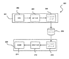
図2に、本発明による、データを圧縮/伸長するための枠組み(フレームワーク)200を示す。この枠組み200には、コーダ(符号化器)部201及びデコーダ(復号化器)部203が含まれ、これらが一緒になって「コーデック」を形成する。コーダ部201は、変換モジュール202、量子化器204、及びデータをファイル208に記憶するために圧縮するエントロピー・エンコーダ(符号化器)206を含む。こうしたファイル208を伸長するために、デコーダ部203は、逆変換モジュール214、逆量子化器212、及びデータを使用する(例えば、ビデオデータの場合には視聴する)ために伸長するエントロピー・デコーダ210を含む。
(Description of preferred embodiments)
FIG. 2 shows a
使用中には、変換モジュール202が、逆相関(減相関、デコリレーション)を目的として、(ビデオデータの場合には)複数の画素の可逆の変換を実行して、この変換は線形変換であることが多い。次に、量子化器204が変換値の量子化を行って、その後にエントロピー・エンコーダ206が、量子化した変換係数をエントロピー符号化する働きをする。
In use, transform
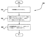
図3に、本発明によりデータを圧縮/伸長する方法300を示す。1つの実施例では、この方法300を、図2の変換モジュール202に関連して、変換モジュール202が可逆の変換を実行する方法で実行することができる。しかし、方法300は所望のものに関連して実現することができる。
FIG. 3 illustrates a
操作302では、データを圧縮するための内挿補間公式を受け取る(例えば、メモリー等から識別して取得する)。本実施例の関係では、データは圧縮可能なあらゆるデータとする。さらに、前記内挿補間公式は、内挿補間(例えばウェーブレットフィルタ等)を用いたあらゆる公式を含むことができる。
In
操作304では、前記内挿補間公式が少なくとも1つのデータ値を必要とするか否かを判定し、ここでは必要なデータ値が入手不可能である。こうしたデータ値は、前述したデータのあらゆる部分集合を含むことができる。必要なデータ値が入手不可能であるとは、これらの必要なデータ値が不在である、範囲外である、等であり得る。
In
その後に、外挿補間演算を実行して、必要で入手不可能なデータ値を生成する。操作306では、外挿補間公式は外挿補間を用いたあらゆる公式を含む。この方式により、データの圧縮を拡張する。
Thereafter, extrapolation is performed to generate necessary and unavailable data values. In
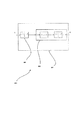
図4に、方法300を実行する対象のデータ構造400を示す。図に示すように、変換中に、複数のデータ値402が関係する内挿補間公式403によって、「最良の適合(ベストフィット)」401を達成することができる(図3の方法300の操作302を参照)。データ値402のうちの1つが入手不可能であることが判明していれば(404参照)、前記外挿補間公式を用いて、こうした入手不可能なデータ値を生成することができる。以上の技法の1つの好適な実現に関する選択肢的な詳細を、以下に図5を参照して詳細に説明する。
FIG. 4 shows a
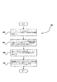
図5に、本発明によりデータを圧縮/伸長する方法500を示す。選択肢として、この方法500を、図2の変換モジュール202に関連して、変換モジュール202が可逆の変換を実行する方法で実行することができる。しかし、方法500は所望のものに関連して実現することができる。
FIG. 5 illustrates a
方法500は、ウェーブレットフィルタ用のエッジフィルタを生成する技法を提供する。最初に、操作502では、ウェーブレット方式を分析して、ウェーブレットフィルタが近似する局所的な導関数を決定する。次に、操作504では、ウェーブレットフィルタの特性及び利用可能なサンプル数にもとづいて、外挿補間に使用する多項式の次数を選定する。次に、前記選定した多項式の次数を用いて、ウェーブレットフィルタ毎の外挿補間公式を導出する(操作506参照)。さらに、操作508では、前記外挿補間公式を、各場合において利用可能なサンプルと共に利用して、特定エッジ(縁)のウェーブレットケースを導出する。
ヴァンデルモンド(Vandermonde)型行列を用いて前記係数について解く選択肢的な方法は、付録Aに記載する。さらに、好適な外挿補間公式に関する追加的で選択肢的な情報及び関連情報を、以下に詳細に説明する。 An alternative method of solving for the coefficients using a Vandermonde matrix is described in Appendix A. In addition, additional optional information and related information regarding the preferred extrapolation interpolation formula is described in detail below.
Y2N-1を左側から近似するために、二次多項式を左側から当てはめることができる。利用可能な値を用いて、2N-1における二次導関数の半分の負値を近似することは、次式1.1Rのようになる。この外挿補間二次式の可能な決定の1つを、付録Aに記載する。
点が最右端である際には、式1.1の代わりにしき1.1Rを用いることができる(発明の背景を参照)。上式で、3を掛けることは、(ビット)シフトと(1の)加算で達成することができる。3で割ることの方がより手間がかかる。最右端の指標が2N-1であるこの場合については、式1.2によってY2N-2を計算することには全く問題がない(発明の背景を参照)。最右端の点の指標が偶数(例えば2N)である場合には、式1.1については問題ないが、式1.2には欠けている値がある。ここでの目的は、前に計算した奇数の指標Yだけ、この問題の場合にはY1及びY3を用いて、偶数のXからYの推定値を減算することにある。指標2Nにおいて要求されたこの推定値は、上述したように、線形外挿補間によって得ることができる。適切な公式は、次式1.2Rによって与えられる。
左側の境界についても、これに対応する状況が当てはまる。要求される外挿補間を左側からよりもむしろ右側(内側)から行うエッジフィルタが適用される。この場合には、適切なフィルタは次式1.1L及び1.2Lによって表わされる。
これらの外挿補間境界フィルタ用の逆変換フィルタは、元のフィルタと同様に、即ち逆の代入によって得ることができる。この逆変換境界フィルタは、前向き境界フィルタを用いるのと全く同じ状況で、標準的なフィルタの代わりに用いることができる。こうしたフィルタは、次式2.1Rinv、2.2Rinv、2.1Linv、及び2.2Linvによって表わされる。
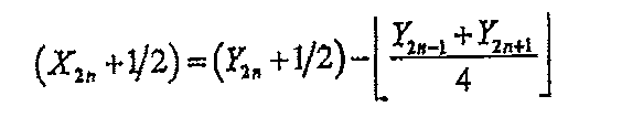
従って、1つの実施例は、フィルタの視覚特性を保ちつつ、従来技術の追加的なステップを回避する5−3フィルタの再公式化を利用することができる(例えば、次式3.1、3.1R、3.2、3.2L参照)。
こうした公式化では、上述した追加を回避するために、特定の係数を1/2のオフセットまたはバイアスを伴って計算する。なお、この公式化では1/2の加算が多いように見えるが、実際の計算では、これらの加算を行う必要がない。式3.1及び3.1Rでは、1/2の加算の影響が相殺されていることがわかり、従って、これらの加算を入力データに適用する必要はない。その代わりに、カッコ内の項(Y0+1/2)等は、係数として実際に計算して記憶して、ウェーブレット変換ピラミッドの次のレベルに渡す量の名前として理解することができる。 In these formulations, certain coefficients are calculated with a 1/2 offset or bias to avoid the additions described above. In this formulation, it seems that there are many additions of 1/2, but it is not necessary to perform these additions in actual calculations. In equations 3.1 and 3.1R, it can be seen that the effects of 1/2 addition are offset, and therefore these additions do not need to be applied to the input data. Instead, the terms in parentheses (Y 0 +1/2) etc. can be understood as names of quantities that are actually calculated and stored as coefficients and passed to the next level of the wavelet transform pyramid.
ちょうど前の場合のように、JPEG−2000逆フィルタは、次式4.2、4.2L、4.1、4.1Rのように再公式化することができる。
ここに見られるように、逆向きの計算の入力として取得した値は、式3.1〜3.2Lにおける前向き計算によって生成されるのと同じ項であり、1/2による補正を明示的に計算する必要は全くない。 As can be seen here, the value obtained as the input for the reverse calculation is the same term that is generated by the forward calculation in Equations 3.1-3.2L, and it is necessary to explicitly calculate the correction by 1/2 There is no.
このようにして、ウェーブレット変換の計算中に実行する算術演算の総数が低減される。 In this way, the total number of arithmetic operations performed during the wavelet transform calculation is reduced.
(選択肢的な特徴)
図2〜5のシステム及び方法に関連して用いることのできる追加的で選択肢的な特徴及び技法を以下に説明する。なお、こうした選択肢的な特徴は、厳密には例示目的で説明するものであり、限定的なものではない。さらに、こうした特長は、以上の図2〜5のシステム及び方法とは無関係に実現することができる。
(Optional features)
Additional optional features and techniques that can be used in connection with the systems and methods of FIGS. 2-5 are described below. It should be noted that these optional features are described strictly for illustrative purposes and are not limiting. Furthermore, such features can be realized independently of the systems and methods of FIGS.
一般的な動作の特徴
使用中には、変換モジュール(例えば図2の変換モジュール202等)は、画像をサブバンドに分離するフィルタバンクとして作用するウェーブレット・ピラミッドを利用することができ、これらのサブバンドの各々が約1オクターブ(即ち係数2)をカバーする。各オクターブには、水平、垂直、及びチェッカーボード(白黒交互の碁盤模様)の形に対応する3つのサブバンドが存在し得る。1つの実施例では、前記ピラミッドを一般に3〜5レベルの深さにして、同数のオクターブをカバーすることができる。元の画像が少しでも平滑であれば、ウェーブレット係数が急速に減少する。画像が2/3のホルダー(Holder)係数を有することがあり、このことは、この画像が導関数の2/3を有することをおよそ意味する。ウェーブレット係数を絶対値が減少する順に整列させれば、これらの絶対値はN-Sの割合で減少するように見え、ここにNは列内の位置であり、Sは画像の平滑度である。
General Operational Features In use, a transform module (eg, transform
ウェーブレット・ピラミッドを形成した後に、量子化器(例えば図2の量子化器204等)によってウェーブレット係数をスケーリング(拡大縮小、量子化)して、視聴条件及び人間の視覚コントラスト感度曲線(CSF:Contrast Sensitivity Curve)に整合する結果を出す。人間の視覚系(HVS:Human Visual System)の特性を考慮することによって、クロマ(色度、彩度)のサブバンドを符号化するために使用するビット数を大幅に低減することができる。
After the wavelet pyramid is formed, the wavelet coefficients are scaled (scaled, quantized) by a quantizer (for example, the
必要なシリコン領域を最小にして実現可能な高速アルゴリズムを提供するために、従来の算術的な符号化器(コーダ)の使用を回避することができる。例えば前述したように、乗算器は、シリコン領域内では非常に高価になるので、回避することができる。さらに、こうしたアルゴリズムは、個別の実行要素毎に非常に良好な「高速パス(径路)」を持つことができる。 In order to provide a fast algorithm that can be implemented with minimum required silicon area, the use of conventional arithmetic encoders (coders) can be avoided. For example, as described above, the multiplier is very expensive in the silicon region and can be avoided. Furthermore, such an algorithm can have a very good “fast path” for each individual execution element.
前記コーデックは、2つのインタレース(飛越し走査)ビデオフレームの画像グループ(GOP:Group of Pictures)、境界用のエッジフィルタ、中間的なフィールド画像圧縮、及びブロック圧縮構造を用いることができる。小型単一チップ用の実現の特定の特徴は、次の表1のようにすることができる。
(表1)
・1つの実現は短いウェーブレットベースを用いることができ、これらはHVSに整合すべく量子化した自然な光景(シーン)画像に焦点を置く者に特に適している。この実現は、加算及びシフト(桁ずらし)で達成することができる。フィールド毎の、水平方向の5つのフィルタの適用及び垂直方向の3つのフィルタの適用により生成したマラー(Mallat)ピラミッドを用いることができる。このことは動的な係数を有するフィルタを生成し、これらは、ローパス(低域通過)フィルタにおける2つの係数、及びウェーブレットフィルタにおける2つ、4つ、または6つの係数(12個のウェーブレット・サブバンドを生じさせる)である。修正したエッジフィルタをブロック及び画像の境界付近で用いて、これにより実際の画像値を利用することができる。結果的なビデオ・ピラミッドは実質的に0の列を有し、実質的に非0の列も有する。従って、符号化は表検索(テーブル・ルックアップ)によって効率的に行うことができる。
・他の解決法は、MPEG的な方法で用いる動き補償探索の代わりに、3Dウェーブレット・ピラミッドによる動画像圧縮を用いることができる。時間方向の変換圧縮を、4フィールドのGOPに適用することができる。2レベルの時間マラー・ピラミッドをテンソル積として空間ピラミッドと共に用いることができる。線形エッジフィルタを密レベルで、修正ハール(Haar)フィルタを粗レベルで用いて、4つの時間サブバンドを生成することができる。これらの時間サブバンドの各々が圧縮されている。
・処理を、各々が32画素の走査線8本から成るブロックの処理に落とすことができる。このことは、RAMの必要量を、RAMをASICそのものの内部に配置できるような値まで低減する助けとなる。このことは、チップの個数を低減して、RAMの帯域要求を満足することを簡単にする。圧縮処理は、ストライプ毎に実行することができる(ストライプ当たり2回の通過)。
・さらに他の実施例は、ウェーブレット係数の量子化を用いて、圧縮のさらなる改善を達成することができる。量子化の分母は2のべき乗であり、シフトによって実現可能である。量子化は、スケーリング係数を各サブバンドに割り当てる処理とすることができ、サブバンド内の各係数に対応するスケーリング係数を乗じて、スケーリングした係数を整数化する。
The codec can use two interlaced video frame image groups (GOPs), boundary edge filters, intermediate field image compression, and block compression structures. Specific features of the implementation for a small single chip can be as shown in Table 1 below.
(Table 1)
One implementation can use short wavelet bases, which are particularly suitable for those focusing on natural scene (scene) images quantized to match HVS. This realization can be achieved with addition and shift (digit shift). A Mallat pyramid generated by applying five horizontal filters and three vertical filters per field can be used. This produces a filter with dynamic coefficients, which are two coefficients in a low-pass filter and two, four, or six coefficients in a wavelet filter (12 wavelet sub-filters). Give rise to a band). The modified edge filter can be used near the boundary between the block and the image so that the actual image value can be used. The resulting video pyramid has substantially zero columns and also has substantially non-zero columns. Therefore, encoding can be performed efficiently by table lookup (table lookup).
Other solutions can use video compression with 3D wavelet pyramids instead of motion compensated search used in MPEG-like methods. Transform compression in the time direction can be applied to a 4-field GOP. A two-level temporal muller pyramid can be used as a tensor product with a spatial pyramid. Four temporal subbands can be generated using a linear edge filter at a fine level and a modified Haar filter at a coarse level. Each of these time subbands is compressed.
Processing can be reduced to processing of blocks each consisting of 8 scan lines of 32 pixels. This helps to reduce the RAM requirement to a value that allows the RAM to be placed inside the ASIC itself. This makes it easy to reduce the number of chips and satisfy the RAM bandwidth requirements. The compression process can be performed for each stripe (2 passes per stripe).
Still other embodiments can use wavelet coefficient quantization to achieve further improvements in compression. The denominator of quantization is a power of 2 and can be realized by shifting. The quantization may be a process of assigning a scaling coefficient to each subband, and the scaled coefficient is converted to an integer by multiplying the scaling coefficient corresponding to each coefficient in the subband.
他の選択肢として、ウェーブレットフィルタを選択的に多相フィルタに置き換える。1つの実施例では、こうした置き換えを、データ圧縮/伸長システムの変換モジュールで行うことができる(例えば、図2の変換モジュール202及び/または逆変換モジュール214)。もちろん、こうした特長は、本明細書に記載の他の種々の特徴とは無関係に実現することができる。この選択肢的な特徴に関するより好適な情報を以下に記述する。
Another option is to selectively replace the wavelet filter with a polyphase filter. In one embodiment, such replacement can be performed by a conversion module of the data compression / decompression system (eg,
本実施例では、ビデオ圧縮コーデックの設計において、従来の[例えば、有限インパルス応答(FIR:Finite Impulse Response)]の情報廃棄または平滑化フィルタをウェーブレット情報保存フィルタと組み合わせることができる。FIRフィルタは単一で使用されるのに対し、ウェーブレットフィルタは常に相補対をなす点で、FIRフィルタをウェーブレットフィルタと区別することができる。また、ウェーブレット変換におけるFIRフィルタは必ずしも、多相フィルタバンクとしての互いにの関係を持たない。 In this embodiment, in the design of a video compression codec, a conventional [for example, Finite Impulse Response (FIR)] information discarding or smoothing filter can be combined with a wavelet information storage filter. A FIR filter can be distinguished from a wavelet filter in that a single FIR filter is used, whereas a wavelet filter always forms a complementary pair. In addition, the FIR filters in the wavelet transform do not necessarily have a mutual relationship as a polyphase filter bank.
ビデオ圧縮は3ステップのプロセス(処理過程)で実行することができ、時として他のステップを追加するが、3つの主な段階は前述したように、変換、量子化、及びエントリ符号化である。これらの操作は通常、一般に行われているように、量子化中に情報を廃棄するに過ぎない。実際に、この操作を省略すれば、無損失(ロスレス)圧縮法となり得る。しかし、無損失圧縮は、有損失圧縮よりもずっと小さい圧縮比に限られ、有損失圧縮は、人間の視覚系を利用して、復号化した結果においては、視覚的に差のない情報、あるいは視覚的な差を無視できる情報を廃棄する。 Video compression can be performed in a three-step process, sometimes adding other steps, but the three main stages are transformation, quantization, and entry coding as described above. . These operations usually only discard information during quantization, as is commonly done. In fact, if this operation is omitted, a lossless compression method can be obtained. However, lossless compression is limited to compression ratios that are much smaller than lossy compression, and lossy compression uses the human visual system to decode information that is not visually different, or Discard information that can ignore visual differences.
許容できる結果において失われていることのある視覚情報の1つのクラスが、微細情報である。ビデオ圧縮に用いられる大部分の変換プロセスが、量子化ステップによって微細情報を廃棄することができるが、これらの変換プロセスは、直接的なローパスフィルタの実現よりも低い効率あるいは低い視覚的忠実性で変換を行う。 One class of visual information that may be lost in acceptable results is fine information. Most conversion processes used in video compression can discard fine information through quantization steps, but these conversion processes are less efficient or less visual fidelity than direct low-pass filter implementations. Perform conversion.
平滑化フィルタを実現する1つの方法は、FIR構造を用いることによるものである。平滑化フィルタを実現する代わりの方法は、無限インパルス応答(IIR:Infinite Impulse Response)構造を用いることによるものである。 One way to implement a smoothing filter is by using an FIR structure. An alternative way to implement the smoothing filter is by using an Infinite Impulse Response (IIR) structure.
画像またはデータ列の大きさを変化させる際には、関連するFIRフィルタから成る多相フィルタバンク(PFB:Polyphase Filter Bank)を用いることができる。こうした方法は、一部の詳細部分を除去して、さらなる処理用の対応するより小さい画像を生成することによって、画像を処理する。 When changing the size of an image or a data string, a polyphase filter bank (PFB) composed of related FIR filters can be used. Such methods process the image by removing some details and generating a corresponding smaller image for further processing.
多相フィルタバンクは、同じ帯域あるいは周波数選択特性を共用するが、元のサンプル上あるいはサンプル間の異なる位置を内挿補間した画素を生成する一組のFIRフィルタを含むことができる。 A polyphase filter bank can include a set of FIR filters that share the same band or frequency selection characteristics but generate pixels that are interpolated at different positions on or between the original samples.
例えば、多相フィルタバンクを用いて、画像(即ちビデオのフレーム)を元の幅の2/3に縮小することができる。多相フィルタバンクは、元の各画素の中間に内挿補間画素を算出して、元の位置に平滑化した画素を算出し、そして結果的な画素流(画素ストリーム)の3画素毎に1画素のみを保持することによって、このことを行う。 For example, a polyphase filter bank can be used to reduce an image (ie, a frame of video) to 2/3 of its original width. The polyphase filter bank calculates an interpolated pixel in the middle of each original pixel, calculates a pixel smoothed to the original position, and 1 for every 3 pixels in the resulting pixel stream (pixel stream). This is done by keeping only the pixels.
この方法により、保持されない画素の計算を省略することができ、画像の大きさを低減するより効率的な方法がもたらされる。このプロセスは、他の合理的な、部分的な大きさの変更に容易に広げられる。このようにして、多相フィルタバンクが小量の微細部分を円滑に除去して、1未満の係数で画像をスケーリングすることができる。この係数は1/2より大きくすることができる。 This method eliminates the computation of unretained pixels and provides a more efficient way to reduce image size. This process is easily extended to other reasonable, partial size changes. In this way, the polyphase filter bank can smoothly remove small amounts of fines and scale the image with a factor of less than one. This factor can be greater than 1/2.
本発明は、多相フィルタをウェーブレットベースの画像圧縮プロセスの第1段として用いることによって、円滑な細部除去の利点を、ウェーブレット変換符号化の画質と組み合わせる。この組合せを用いることによって、多相バンクフィルタを用いることによる、円滑で、高品質で、アーティファクト(歪像)のない微細部分、及びこれらの微細部分を表現するために必要なビットを除去する利点を、ウェーブレット変換を画像及びビデオ圧縮の基本として用いることによる高速で効率的な演算及び高画質という周知の利点に加えることができる。 The present invention combines the benefits of smooth detail removal with the image quality of wavelet transform coding by using a polyphase filter as the first stage of a wavelet-based image compression process. Advantages of using this combination to remove smooth, high quality, artifact-free fines and the bits needed to represent these fines by using a polyphase bank filter Can be added to the well-known advantages of fast and efficient computation and high image quality by using the wavelet transform as the basis for image and video compression.
本発明の方法の第1の実施例では、まず多相フィルタバンクを画像の一方向、通常は水平方向に適用して、次に、従来の方法における量子化及び符号化の前に、ウェーブレット変換を画像に適用することができる。 In a first embodiment of the method of the present invention, the polyphase filter bank is first applied in one direction of the image, usually the horizontal direction, and then the wavelet transform before quantization and coding in the conventional method. Can be applied to the image.
本発明の方法の第2の実施例では、最初の特定方向のウェーブレット演算の前に、この方向に多相フィルタを適用することができるが、他の方向のウェーブレット演算後に行うこともあり得る。 In the second embodiment of the method of the present invention, the polyphase filter can be applied in this direction before the first wavelet operation in a specific direction, but it may be performed after the wavelet operation in other directions.
さらに他の実施例では、いくつかの方向の各々について、この方向の最初のウェーブレット演算の前に、この方向に多相フィルタを適用することができるが、他の方向のウェーブレット演算後に行うこともあり得る。 In yet another embodiment, for each of several directions, a polyphase filter can be applied in this direction before the first wavelet operation in this direction, but can also be done after wavelet operations in other directions. possible.
少なくとも一部のウェーブレットまたはDCT変換の段階の前に無損失のフィルタリング(フィルタ処理)ステップを適用する本発明の方法には、いくつかの利点がある。例えば、ウェーブレット的な関数に限定されず、FIR設計または多相設計のようなフィルタを、より高品位及び少ないアーティファクトのために設計することができる。ウェーブレットフィルタは、情報を廃棄することなしに2つの部分に分ける対の形に設計することができる。 The method of the present invention that applies a lossless filtering step before at least some wavelet or DCT transform stages has several advantages. For example, not limited to wavelet-like functions, filters such as FIR designs or polyphase designs can be designed for higher quality and fewer artifacts. A wavelet filter can be designed in pairs to divide it into two parts without discarding information.
変換操作の後よりも前に変換操作を適用することは、変換演算をより少ないデータに対して実行し、従って、演算時間をより少なくして、演算中の中間的な記憶容量をより少なくすることができることを意味する。変換は一般に圧縮プロセスの高価な部分であるので、この低減は、圧縮プロセス全体にわたって速度及び効率の大幅な改善をもたらす。 Applying the conversion operation before after the conversion operation performs the conversion operation on less data, thus reducing the calculation time and reducing the intermediate storage capacity during the operation Means that you can. Since conversion is generally an expensive part of the compression process, this reduction provides a significant improvement in speed and efficiency throughout the compression process.
パイルを用いた平方ウェーブレット変換
さらに他の操作として、データ量を低減することによって、エントロピー符号化に関連する演算量を低減する。1つの実施例では、こうした低減を、データ圧縮/伸長システムの量子化器において行う(図2の量子化器204参照)。もちろん、こうした特徴は、本明細書に記載した他の種々の特徴とは無関係に実現することができる。この選択肢的な特徴に関するより好適な情報を以下に述べる。
Square Wavelet Transform Using Pile As another operation, the amount of calculation related to entropy coding is reduced by reducing the amount of data. In one embodiment, such reduction is performed in the quantizer of the data compression / decompression system (see
本実施例では、パイルを、復号化演算における演算として用い、従ってパイルは、これに続くステップの演算に直ちに使用できる。パイルに関するさらなる情報は、付録Bに記載する。 In this embodiment, the pile is used as an operation in the decoding operation, and thus the pile can be used immediately for the operation of the subsequent step. Additional information regarding piles is provided in Appendix B.
行列(マトリクス)データの希薄表現と称されるものを提供することは、特定の演算分野ではよく知られている。通常の行列は、行列要素である数の完結したアレイとして表現され、「稠密な」表現と称される。一部のプログラム・パッケージは、「希薄行列」に対する記憶、変換、及び操作を行い、希薄行列では0のエントリは1つずつ明示的に表現せず、暗示的に表現する。こうした「希薄な」表現の1つはゼロ−ラン(ゼロ列長)符号化であり、この符号化では、まとまって発生する0の個数によってゼロを表現する。この個数そのものは、0にも(2つの非ゼロ値が隣接している際)、1にも(単独のゼロ値)、より大きい値にもなり得る。 Providing what is referred to as a sparse representation of matrix data is well known in certain computational fields. A normal matrix is represented as a complete array of numbers that are matrix elements, and is referred to as a “dense” representation. Some program packages store, transform, and operate on a “sparse matrix” where the zero entries are not explicitly represented one by one, but implicitly. One such "sparse" representation is zero-run (zero sequence length) coding, where zero is represented by the number of zeros that occur together. This number itself can be 0 (when two non-zero values are adjacent), 1 (single zero value), or a larger value.
しかし、ビデオデータが行列でない場合には、通常はこのビデオデータに対して行列演算(即ち、乗算、逆行列計算、固有値分解、等)は適用しない。希薄行列演算の基礎的な原理を取り出して、ビデオ変換に移すことができる。 However, when the video data is not a matrix, normally, matrix operations (that is, multiplication, inverse matrix calculation, eigenvalue decomposition, etc.) are not applied to the video data. The basic principles of sparse matrix operations can be taken and moved to video conversion.
簡単に言えば、パイルは対のアレイから成り、各対が、非ゼロのアイテム(項目)の通常データのアドレス(またはオフセット)を、当該アイテムの値と共に与える。これらのアドレスまたはオフセットは並べ替え(ソート)した順序であり、このため、パイルを調べて、非ゼロ要素に対して、これらの要素のデータセット(データ集合)全体中の箇所を考慮に入れて操作を行うことによって、データ全体を隅から隅まで調べることができる。 Briefly, a pile consists of an array of pairs, each pair giving the address (or offset) of the normal data of a non-zero item (item) along with the value of that item. These addresses or offsets are in a sorted order, so for a non-zero element, consider the location in the entire data set (data set) for these elements. By performing the operation, the entire data can be examined from corner to corner.
パイルは、いくつかのデータ・アイテムに対して一度に行う同一操作を用いてデータを並列的に処理するコンピュータ(即ち:SIMDプロセッサ(Single Instruction stream-Multiple Data stream Processor:同一命令で複数データを並列処理するプロセッサ))、及び制御の条件転移を行う比較的高価なコンピュータ上で効率的に実現可能なように特別に設計する。これらのプロセッサは、一般的な使用では、ビデオ及びオーディオを取り扱うために用いられ、時として「メディア・プロセッサ」と称される。 A pile is a computer that processes data in parallel using the same operations performed on several data items at once (ie: SIMD processor (Single Instruction stream-Multiple Data stream Processor)) Processor)), and specially designed to be efficiently implemented on a relatively expensive computer that performs control condition transitions. These processors are used to handle video and audio in general use and are sometimes referred to as “media processors”.
2つのデータセットに対して何らかの操作を実行する必要があり、両方のデータセットが希薄である際には、データが稠密に表現される際にはしなかった考慮が生じる。即ち、「データ・アイテムが互いに一致するのはいつか」ということである。 Some operations need to be performed on the two data sets, and when both data sets are sparse, considerations that were not made when the data are expressed densely arise. That is, “When do data items match each other?”.
パイルとして表現される2つのデータセットに対する操作において、一致しているデータ・アイテムを識別するための基本的な操作は「マッチ・アンド・マージ(整合と結合)」と称される。2つのパイルを調べる際には、開始後の操作毎に、各パイルからのアドレス、及び出力値を生成した直後の、この出力値を割り当てたアドレスを得ることができる。値を生成して割り当てることができる次のアドレスを見出すために、2つの入力パイルが表現する2つのアドレスの小さい方を見出すことができる。両方のパイルがこのアドレスに合意すれば、各パイルからの利用可能なデータ・アイテムが存在し、これら2つの値に対して操作を行って所望の結果を生成することができる。そして、両方のパイル上の次のアイテムに進むことができる。 In the operation on two data sets expressed as piles, the basic operation for identifying matching data items is called “match and merge”. When examining two piles, for each operation after the start, an address from each pile and an address to which the output value is assigned immediately after the output value is generated can be obtained. To find the next address that can be generated and assigned a value, the smaller of the two addresses represented by the two input piles can be found. If both piles agree on this address, there are data items available from each pile, and operations can be performed on these two values to produce the desired result. You can then proceed to the next item on both piles.
2つのパイル中の次のアドレスが異なる場合には、一方のパイル(データセット)中には非ゼロ値が存在するが、他方のデータセット(パイルによって暗示的に表現される)中にはゼロ値が存在し、1つの値及び0に対して演算を行って、ある値を生成することができる。あるいはまた、入力が0である際に、実行中の演算が0を生成すれば、何の値も生成されない。いずれの場合にも、小さいほうのアドレスを有するパイルのみについて、次のアイテムに進むことができる。 If the next addresses in the two piles are different, there is a non-zero value in one pile (data set) but zero in the other data set (implicitly represented by the pile) A value exists and an operation can be performed on one value and 0 to produce a value. Alternatively, if the input is 0 and the operation being performed generates 0, no value is generated. In either case, only the pile with the smaller address can proceed to the next item.
結果の値はある箇所に配置し、この箇所は、(アドレスを2つ以上進める際に常に明示的に0を書き込むことによる)稠密なアレイか、出力パイル中かのいずれかとする。 The resulting value is placed at a location that is either a dense array (by always explicitly writing 0 when advancing two or more addresses) or in the output pile.
前述したように、ウェーブレット変換は、ウェーブレットフィルタ対を一組のデータに反復的に適用することであり、このデータは一次元でも二次元以上でもよい。ビデオ圧縮用には、2Dウェーブレット変換(水平及び垂直)または3Dウェーブレット変換(水平、垂直、及び時間)を用いることができる。 As mentioned above, wavelet transform is the iterative application of a wavelet filter pair to a set of data, which may be one-dimensional or more than two-dimensional. For video compression, 2D wavelet transform (horizontal and vertical) or 3D wavelet transform (horizontal, vertical and time) can be used.
ビデオ圧縮器内の変換段の意図は、原画像のエネルギーまたは情報を集めて、画像または画像シーケンス(列)中の局所的な類似性及びパターンを利用することによって、できる限り小さい形にすることにある。あり得るすべての入力をできる限り圧縮することのできる圧縮器はないが、「一般的な」入力に対して良好に作用するように圧縮器を設計して、これらの圧縮器が「ランダム」あるいは「病的」な入力を圧縮し損なうことを無視することはできる。 The intent of the conversion stage in the video compressor is to be as small as possible by collecting the energy or information of the original image and utilizing local similarities and patterns in the image or image sequence (column) It is in. No compressor can compress all possible inputs as much as possible, but the compressors are designed to work well for “generic” inputs so that these compressors are “random” or The failure to compress “pathological” input can be ignored.
変換が良好に作用して、画像情報が良好に集められて少数の変換係数にされると、残りの係数の多くは0になる。 If the transform works well and the image information is collected well into a small number of transform coefficients, many of the remaining coefficients will be zero.
前述したように、結果を量子化することも、ビデオ圧縮器の一段階である。この段階では、0に近い計算値は0で表現する。最終的な変換結果を量子化するか、あるいは、最終的な変換結果の量子化に加えて算出した係数を量子化するよりも、あるいはよりも、ウェーブレット変換の演算中に、算出した係数を量子化する方が望ましいことがある。 As mentioned above, quantizing the result is also a stage of the video compressor. At this stage, a calculation value close to 0 is expressed as 0. Quantize the final transform result, or quantize the calculated coefficient during the wavelet transform operation, rather than quantize the calculated coefficient in addition to quantizing the final transform result. It may be desirable to
従って、一部のウェーブレット係数データ中に多くの0を得ることがあり、このことは、データに対する演算をもっと行う必要がある間に起り得る。 Thus, many zeros may be obtained in some wavelet coefficient data, which may occur while more operations on the data need to be performed.
これに加えて、圧縮した画像またはビデオを表示するために復号化している際には、エントロピー符号化した重要な係数から、完全に満たされた(値を入れられた)表示用画像に向けての作業を行うことができる。最初の復号化ステップ、即ちエントロピー符号の復号化の一般的な出力は、デフォルトで0であると考えることのできる非重要な係数を多数伴う重要な係数の集合である。 In addition, when decoding to display a compressed image or video, from the entropy-encoded key coefficients, towards a fully filled (filled) display image Can be done. The general output of the first decoding step, the decoding of the entropy code, is a set of important coefficients with many non-critical coefficients that can be considered to be zero by default.
このことが生じた際には、多くの0を伴う稠密なデータを希薄な表現に変換することは価値があり、このことは、前述したようにデータをパイル化することによって行うことができる。パイル表現は前記ゼロ−ラン表現に似ているが、通常は、ランレングス(ラン長:アドレスの差)ではなく、アドレスまたはオフセットを記憶する。このことは、パイルを作成するため、及びこのパイルを後に稠密な表現に拡張するための高速の処理を共に可能にする。 When this happens, it is worthwhile to convert dense data with many zeros into a sparse representation, which can be done by piling the data as described above. The pile representation is similar to the zero-run representation, but usually stores an address or offset rather than a run length (run length: address difference). This allows both high speed processing to create a pile and to later expand this pile to a dense representation.
復号化の場合には、データが稠密な形式ではなく、エントロピー・デコーダ内で直接パイルを構成する方がより自然である。 In the case of decoding, it is more natural to construct the pile directly in the entropy decoder rather than in a dense form of data.
ウェーブレット変換の処理は、パイル化の処理を受けるいくつかの場合をもたらし、これらを次の表2に示す。
(表2)
・伸長、両帯域をパイル化
・伸長、一方の帯域をパイル化
・伸長、入力がパイル化で出力が稠密
・圧縮、入力が稠密で出力がパイル化
The wavelet transform process results in several cases that undergo a pile process, which are shown in Table 2 below.
(Table 2)
・ Stretching, pile both bands ・ Stretching, pile one band ・ Stretching, pile input and dense output ・ Compression, dense input and pile output
1つの例を考える:圧縮されたビデオのフレームの復号化であり、符号化プロセスが、0に量子化される非常に多くの係数を生成している。伸長の最初の段階は、非ゼロ係数のエントロピー符号化またはビット符号化を元に戻し、フレーム内の各値の値及びその位置を与える。このことは単にパイルで表現される情報であり、間にあるすべてのゼロ値に明示的な値を入れることによってこの情報を直ちに稠密表現に拡張するよりも、パイルを用いてこの情報を記憶する方が非常に好都合である。 Consider one example: decoding a frame of compressed video, where the encoding process has produced a very large number of coefficients that are quantized to zero. The first stage of decompression reverses entropy coding or bit coding of non-zero coefficients, giving the value of each value and its position in the frame. This is simply information that is represented in piles, rather than using a pile to store this information rather than immediately extending this information to a dense representation by putting explicit values for all zero values in between. Is much more convenient.
この段階では、逆ウェーブレット変換によって操作できる係数がある。逆変換の最終結果は、伸長されて直ちに表示可能な画像であり、この画像は一部が粗くなっているに過ぎない。 At this stage, there are coefficients that can be manipulated by inverse wavelet transform. The final result of the inverse transformation is an image that is decompressed and can be displayed immediately, and this image is only partially rough.
逆ウェーブレット変換の第1段階(各段階も同様)は、係数データの2つの領域または「帯域」からデータを取得して、これらのデータを組み合わせて中間的な帯域にするフィルタ演算であり、この中間的な帯域は同じプロセスのさらなる段階で使用する。この第1段階では、両帯域についてのデータが希薄であり、パイルで表現される。この段階の出力もパイルで生成することができ、ゼロに値を入れる必要はない。以下の表3の演算は、「帯域」パイルP1及びP2に対して行い、その結果は新たなパイルRの形で生成され、前記2つの帯域からの係数対に対してフィルタ演算ステップW(p,q)を実行する。
(表3)
while not both EOF(P1), EOF(P2) {
I1=0; I2=0;
guard(P1.index ≦ P2.index, Pile_Read(P1, I1));
guard(P1.index ≦ P2.index, Pile_Read(P2, I2));
Conditional_Append(R, true, W(I1, I2)); };
Destroy_Pile(P1); Destroy_Pile(P2);
The first stage of inverse wavelet transform (same for each stage) is a filter operation that obtains data from two regions or “bands” of coefficient data and combines these data into an intermediate band. The intermediate band is used in a further stage of the same process. In this first stage, the data for both bands is sparse and expressed in piles. The output of this stage can also be generated in a pile and does not need to be zeroed. The operations in Table 3 below are performed on “band” piles P 1 and P 2 , and the result is generated in the form of a new pile R, and the filter operation step W is applied to the coefficient pairs from the two bands. (p, q) is executed.
(Table 3)
while not both EOF (P 1 ), EOF (P 2 ) {
I 1 = 0; I 2 = 0;
guard (P 1 .index ≤ P 2 .index, Pile_Read (P 1 , I 1 ));
guard (P 1 .index ≤ P 2 .index, Pile_Read (P 2 , I 2 ));
Conditional_Append (R, true, W (I 1 , I 2 ));};
Destroy_Pile (P 1 ); Destroy_Pile (P 2 );
なお、以上の演算は、付録Bに示すように、並列演算用に展開することができる。 The above operations can be expanded for parallel operations as shown in Appendix B.
ウェーブレット変換を計算するために要する時間は、希薄表現、パイルを、多くのゼロ値を有する中間結果用に用いることによって低減することができる。こうした方法は、ウェーブレットベースの画像圧縮及びビデオ圧縮製品の性能及び演算効率を改善する。 The time required to compute the wavelet transform can be reduced by using sparse representation, pile, for intermediate results with many zero values. Such a method improves the performance and computational efficiency of wavelet-based image compression and video compression products.
変換範囲の制限
さらに他の選択肢として、データ値を所定のデータ範囲に再構成することに関連する演算量を低減することができる。こうした演算は、単一のクリップ操作のみを実行することによって低減することができる。1つの実施例では、こうした低減を、データ圧縮/伸長システムの逆量子化モジュール(図2の逆量子化器212参照)内で行う。もちろん、こうした特徴は、本明細書に記載した他の種々の特徴とは無関係に実現することができる。この選択肢的な特徴に関するより好適な情報を以下に記述する。
Limiting the conversion range As yet another option, the amount of computation associated with reconfiguring data values into a predetermined data range can be reduced. Such operations can be reduced by performing only a single clip operation. In one embodiment, such reduction is performed in the inverse quantization module of the data compression / decompression system (see
ディジタル画像圧縮及びディジタルビデオ圧縮法では、画像(またはフレーム)を数値のアレイとして表現して、各数値が、領域の明るさ、あるいはこの領域内の特定色(例えば赤色)の量を表現する。これらの領域は画素と称され、上記数値はサンプル値または成分値と称される。 In digital image compression and digital video compression methods, an image (or frame) is represented as an array of numbers, each number representing the brightness of the region or the amount of a particular color (eg, red) within the region. These regions are called pixels, and the above numerical values are called sample values or component values.
画像圧縮またはビデオ圧縮は、広範囲にわたる異なる方法で行われる。前述したように、これらの方法の多くは、変換の演算をステップとして含み、一連の算術演算を通して、画像を表現するサンプルのアレイを、係数と称する数値から成る異なるアレイに変換して、これらの数値は画像情報を含むが、個々の数値は小領域の明るさまたは色に対応しない。変換は同じ画像情報を含むが、この情報は、これらの数値にわたって、圧縮法のさらなる演算にとって有利なように分布する。 Image compression or video compression is done in a wide variety of different ways. As mentioned earlier, many of these methods involve transformation operations as steps, and through a series of arithmetic operations, transform an array of samples representing an image into a different array of numerical values called coefficients. Although the numerical value includes image information, each numerical value does not correspond to the brightness or color of the small area. The transform contains the same image information, but this information is distributed over these numbers in an advantageous manner for further computation of the compression method.
こうした方法によって圧縮した画像またはフレームを再生する際には、圧縮したデータを伸長しなければならない。このことは通常、係数のアレイを取得してサンプルのアレイを生成する逆変換を計算することをステップとして含む。 When an image or a frame compressed by such a method is reproduced, the compressed data must be decompressed. This typically involves taking an inverse transform that obtains an array of coefficients and produces an array of samples.
画像またはフレームのサンプルは一般に、小さいサイズ(桁数)、通常は8バイナリ(二進)ビットの整数によって表現される。こうした8ビットの数は256個の異なる値しか表現できず、これらの応用では、これらの値は一般に、0から255までの範囲の整数[0, 255]であると考えられている。 An image or frame sample is typically represented by an integer of small size (number of digits), usually 8 binary (binary) bits. These 8-bit numbers can only represent 256 different values, and in these applications these values are generally considered to be integers [0, 255] ranging from 0 to 255.
多くの規格及び動作条件が、この範囲より制約された範囲を強いる。例えば、CCIR-601(ITU-R BT. 601-4)ディジタルビデオにおける画素成分(Y, U, V)のサンプル値は、[0, 255]よりも小さい範囲内に存在する。特に、スクリーンの光のある部分における輝度Y成分の有効範囲は、[16, 235]内に存在すべく指定され、クロマ(色度)U、Vの範囲は[16, 240]内に存在すべく指定されている。これらの範囲外の値は、明るさ以外の意味を持ち、例えばシンク・イベント(同期事象)を表わす。 Many standards and operating conditions impose a more constrained range than this range. For example, sample values of pixel components (Y, U, V) in CCIR-601 (ITU-R BT. 601-4) digital video exist within a range smaller than [0, 255]. In particular, the effective range of the luminance Y component in a portion of the screen light is specified to be in [16, 235], and the chroma (chromaticity) U, V ranges are in [16, 240]. Specified. Values outside these ranges have meanings other than brightness and represent, for example, sync events.
画像及びビデオ圧縮法は2つのカテゴリに分けることができ、即ち無損失(ロスレス)及び有損失である。無損失圧縮法は、伸長によって、圧縮用に提供されたのと全く同じ値を生成する方法で動作する。これらの方法については、範囲の問題は存在しない、というのは、出力が入力と同じ数値の範囲を占めるからである。 Image and video compression methods can be divided into two categories: lossless and lossy. The lossless compression method operates in a manner that, by decompression, produces exactly the same value as provided for compression. For these methods, the range problem does not exist because the output occupies the same numerical range as the input.
しかし、有損失圧縮は、元の入力を近似することを想定した伸長出力を生成するに過ぎず、ビット単位で整合しない。この、画像を少し変更するという自由度を利用して、有損失法はずっと大きい圧縮比を得ることができる。 However, lossy compression only generates a decompressed output that is assumed to approximate the original input and does not match bit by bit. Using this degree of freedom to change the image slightly, the lossy method can obtain a much larger compression ratio.
有損失圧縮法の伸長部分では、算出したサンプルが対応する元のサンプルと同一であることが保証されておらず、従って、同じ値の範囲を占めることも保障されていない。従って、画像規格の範囲条件を満足するために、計算値を指定範囲に限定またはクリップ(頭打ち)するステップを含めなければならない。 In the decompression part of the lossy compression method, it is not guaranteed that the calculated sample is identical to the corresponding original sample, and therefore it is not guaranteed to occupy the same value range. Therefore, in order to satisfy the range condition of the image standard, a step of limiting or clipping the calculated value to the specified range must be included.
このクリップするステップを実行する簡単な方法は次の通りである:算出したサンプルs毎に、s>max(最大値)であるか否かをテスト(判定)して、そうであればsをs=maxに設定して、s<min(最小値)であるか否かをテストして、そうであれば、s=minに設定する。 A simple way to perform this clipping step is as follows: For each sample s calculated, test (determine) whether s> max (maximum value), and if so, s Set s = max and test whether s <min (minimum value); if so, set s = min.
このステップを実行する他の方法は、ある演算プラットフォームで見出したMAX及びMIN演算子を使用し、ここでも、各サンプルに2つの操作を適用することができる。以上示した両方の方法、及び他の多くの方法は、加算及び減算のような単純な算術演算よりも、計算が高価になる。 Another way to perform this step is to use the MAX and MIN operators found on some computing platforms, and again, two operations can be applied to each sample. Both of the methods shown above, and many others, are more expensive to compute than simple arithmetic operations such as addition and subtraction.
このプロセスは、画像またはフレーム内のすべてのサンプル値(すべての画素)について別個に実行することができるので、伸長法における演算の重要部分である。なお、通常は十分、要求された範囲内に存在する算出したほとんどすべてのサンプルについて、上記両方のテストがなされておらず、従って両方のテストを演算しなければならない。 This process is an important part of the operation in the decompression method because it can be performed separately for every sample value (all pixels) in the image or frame. It should be noted that both of the above tests have not been performed on almost all the calculated samples that are generally within the required range, and therefore both tests must be calculated.
上述した変換演算は一般に、次の特性を有する:結果的な係数のうちの1つが、フレーム全体かあるいはフレームの主要部分(MPEG技術ではブロック)全体の明るさのレベルを表わす。この係数はDC係数と称される。変換を計算する方法に起因して、DC係数を変更すれば、当該フレームまたはブロック内の全サンプルの値が同様に、即ち行った変更に比例して変更される。従って、例えば、逆変換を計算する直前に、当該ブロック用に適切に選定した定数をDC係数に加算することによって、ブロック内のあらゆるサンプルの値を同量だけ増加させることができる。 The conversion operations described above generally have the following characteristics: one of the resulting coefficients represents the brightness level of the entire frame or the main part of the frame (a block in MPEG technology). This coefficient is called a DC coefficient. Due to the method of calculating the transformation, changing the DC coefficient will change the value of all samples in the frame or block in the same way, i.e. in proportion to the changes made. Thus, for example, immediately before calculating the inverse transform, the value of every sample in the block can be increased by the same amount by adding a constant appropriately selected for the block to the DC coefficient.
圧縮法を実行する計算(コンピュータ)エンジンは一般に、飽和特性のある算術命令を有し、結果が計算されると、この結果がコンテナの表現範囲(8ビット量については[0, 255])を超えていれば、結果をクリップしてこの範囲内に入れる。例えば、飽和減算命令に4及び9の値を与えれば、結果(4-9=)-5がクリップされて、代わりに結果0が戻される。同様に、飽和加算命令は、250+10に対して結果255を戻す。 Computational (computer) engines that perform compression typically have arithmetic instructions with saturation characteristics, and when the result is computed, this result can be expressed in the container representation range ([0, 255] for 8-bit quantities). If so, clip the result into this range. For example, if the values of 4 and 9 are given to the saturation subtraction instruction, the result (4-9 =)-5 is clipped and the result 0 is returned instead. Similarly, the saturation addition instruction returns a result 255 for 250 + 10.
多くの圧縮法における、画素成分値をクリップする低コストの方法を以下に説明し、この方法は、適切な限界への復号化に由来する。本実施例は、部分値にバイアスをもってきて、MAX/MIN演算子の一方のみを残すことによって、飽和算術計算を伴う2つのクリップの一方を実行する。要求される範囲が[llim(下限), ulim(上限)]=[16, 240]である際の、より詳細な例を、次の表4に示す。
(表4)
1.各ブロック内のDC係数にバイアスを加えて、これにより、すべての変換フィルタ後に、各部分が負の値-16(一般化した表現は-llim)だけオフセットされる。
コスト:画像またはブロック当たり1回の算術演算。
2.必ず、逆変換の最終的な算術ステップが0に飽和(クリップ)するようにする。
コスト:大部分の計算エンジンにおいてコストがかからない。
3.224(一般化した表現はulim-llim)による(分割)MAX演算(224に最大化する演算)を適用する。
コスト:サンプル当たり1回のMAX演算。
4.ADD 16(一般化した表現はllim)(16を加算する演算)を用いて、前記バイアスを除去する。直前のMAX演算により、これによるオーバーフローはあり得ないので、このバイアス除去は飽和算術演算を以って行う必要はない。
コスト:サンプル当たり1回のADD(加算)演算。
A low cost method for clipping pixel component values in many compression methods is described below, which derives from decoding to the appropriate limits. This embodiment performs one of the two clips with saturation arithmetic computation by biasing the partial values and leaving only one of the MAX / MIN operators. Table 4 below shows a more detailed example when the required range is [llim (lower limit), ulim (upper limit)] = [16, 240].
(Table 4)
1. A bias is applied to the DC coefficients in each block so that after every transform filter, each part is offset by a negative value -16 (the generalized representation is -llim).
Cost: One arithmetic operation per image or block.
2. Be sure to saturate (clip) the final arithmetic step of the inverse transformation to zero.
Cost: Most computing engines are not expensive.
3. Apply (divide) MAX operation (operation that maximizes to 224) by 224 (the generalized expression is ulim-llim).
Cost: One MAX operation per sample.
4). The bias is removed using ADD 16 (the generalized expression is llim) (the operation of adding 16). Since there is no overflow due to the previous MAX operation, this bias removal need not be performed with a saturation arithmetic operation.
Cost: One ADD (addition) operation per sample.
ここで明らかなように、必要な範囲限定の演算コストは、サンプル当たり2回のMAX/MIN(最大化/最小化)演算から、ブロック当たり1回のADD(加算)演算、1回のMAX(最大化)演算、及び1回の単純なADD(加算)演算に低減される。 As can be seen, the computational cost of the required range is limited from two MAX / MIN (maximization / minimization) operations per sample, to one ADD (addition) operation per block, one MAX ( Maximization) and a single simple ADD (addition) operation.
一部の計算エンジン、例えばEQUATOR MAP-CAプロセッサ上では、本方法の使用による節減は、以上の説明より直ちに明らかである以上に、ずっと大幅なものとなり得る。これらのエンジン上では、いくつかのサンプルを組み合わせてワードにして、同時に演算することができる。しかし、これらの分割演算は、プロセッサの特定部分に限定され、圧縮用途では、性能を限定する元となり得る。こうしたエンジン上では、上記ステップ4におけるADD演算がオーバーフローし得ないということが非常に重要である。ステップ4は、空間分割したADD演算を用いる必要はないが、通常のADD演算を用いて、いくつかのサンプルに対して、これらがあたかも分割されているが如く一度に演算を行うことができる。この通常の演算は、プロセッサの、さほど高負荷がかかっておらず、他の必要な分割演算との重複、あるいは同時実行が可能な部分を用いて行うことができ、逆変換の計算時間の大幅な節約ができる。 On some computing engines, such as the EQUATOR MAP-CA processor, the savings from using this method can be much greater than is readily apparent from the above discussion. On these engines, several samples can be combined into words and operated on simultaneously. However, these split operations are limited to specific parts of the processor and can be a source of performance limitation in compression applications. On such an engine, it is very important that the ADD operation in step 4 cannot overflow. Step 4 does not need to use a spatially divided ADD operation, but can use a normal ADD operation to perform operations on several samples at once as if they were divided. This normal operation is not so heavy on the processor, and can be performed using parts that can be duplicated with other necessary division operations or can be executed simultaneously, greatly increasing the computation time of the inverse transformation. Savings.
図6に、本発明の一実施例によりデータを圧縮するシステム600を示す。選択肢として、システム600を、以上説明したことに関係して実現することができる。しかし、もちろん、システム600はあらゆる所望のことに関係して実現することができる。 FIG. 6 illustrates a system 600 for compressing data according to one embodiment of the present invention. As an option, the system 600 can be implemented in connection with what has been described above. Of course, however, the system 600 can be implemented in any desired context.
システム600は、単一デバイス604上に具現したエンコーダ602を具えて、エンコーダ602は、データを符号化して第1フォーマットの第1圧縮データを生成する。さらに、トランスコーダ606を、エンコーダ602と同じ単一デバイス604上に具現して、トランスコーダ606は第1圧縮データをコード変換(トランスコード)して第2フォーマットの第2圧縮データを生成する。
System 600 includes an
使用中には、データは単一デバイス604で受信される。こうしたデータは単一デバイス604を利用して符号化されて、第1フォーマットの第1圧縮データが生成される。さらに、この第1圧縮データは、単一デバイス604を利用してコード変換されて、第2フォーマットの第2圧縮データが生成される。
In use, data is received at a
1つの実施例では、前記符号化をリアルタイムで行うことができる。さらに、前記コード変換をオフラインで行うことができる。他の実施例では、第1圧縮データをコード変換して、単一デバイス604に結合した通信ネットワークの容量に整合すべく適応させた第2フォーマットの第2圧縮データを生成する。
In one embodiment, the encoding can be performed in real time. Furthermore, the code conversion can be performed off-line. In another embodiment, the first compressed data is transcoded to produce second compressed data in a second format adapted to match the capacity of the communication network coupled to the
選択肢として、第1デコーダを利用して符号化を実行することができる。さらに、図6に示すように、デコーダ及び第2エンコーダを利用してコード変換を実行することができる。 As an option, encoding may be performed using the first decoder. Furthermore, as shown in FIG. 6, code conversion can be performed using a decoder and a second encoder.
さらに、前記第1フォーマットはウェーブレットベースのフォーマットを含むことができる。さらに、前記第2フォーマットはDCTベースのフォーマットを含むことができる。1つの特別な実施例では、前記第2フォーマットがMPEGフォーマットを含むことができる。追加的で選択肢的な特徴に関するより好適な情報を以下に記述する。 Further, the first format may include a wavelet-based format. Further, the second format may include a DCT based format. In one particular embodiment, the second format may include an MPEG format. More suitable information regarding additional optional features is described below.
前述したように、画像及びビデオ・シーケンスを用いた通信モードがいくつか存在する。直接的なリアルタイムの視聴に加えて、画像またはビデオ・シーケンスを捕捉して、後の時間に伝送することができ、この後の時間は、捕捉直後でも、より先の時間まで遅延させてもよい。 As described above, there are several communication modes using images and video sequences. In addition to direct real-time viewing, images or video sequences can be captured and transmitted at a later time, which may be delayed immediately after capture or until a later time .
これに加えて、ビデオ・シーケンスの受信は、テレビを見るようにビデオを見るが記憶しないリアルタイム・モードでも、後の視聴用にシーケンスを記憶する他のモードでも行うことができる。 In addition to this, the video sequence can be received in a real-time mode where the video is viewed but not stored, as in television, or in other modes where the sequence is stored for later viewing.
これらの種々の選択肢は、他の組み合わせに加えて、3通りの使用のシナリオに組み入れられる。これら3通りのシナリオは次の通りである。
1.送信機と受信機が共にリアルタイムで動作する、上述したビデオフォンまたはピクチャフォン(テレビ電話)。この動作は、圧縮、符号化、及び伸長のすべてを、ビデオを捕捉する速度でリアルタイムで実行する必要があり、そして伝送チャンネルは、圧縮したビデオのフルレート(最大速度)を搬送する必要がある。
2.ソースまたはネットワークにおいてビデオを捕捉し記憶して、受信機においてリアルタイムで視聴するストリーム動作。この動作は、リアルタイムの復号化を必要とするが、伝送の前にシーケンスを処理することを可能にする。このモードは、圧縮したビデオのフルレートを搬送するための、少なくともネットワークから受信機までの伝送チャンネルを必要とする。これに加えて、大部分の伝送チャンネルについては、受信機がいくらかの量のシーケンスを一時蓄積(バッファ)して、伝送レート(速度)に変動が存在しても円滑な再生を維持しなければならない。
3.ソースにおいてビデオを捕捉して記憶して、非リアルタイムで受信機に伝送して、受信機において後の再生用に記憶するメッセージまたはファイル転送モード。このモードは、リアルタイム・ビデオのフルレートが搬送不可能な伝送チャンネル上での動作を可能にし、そして受信者が繰り返し再生、一時停止することを可能にするか、さもなければ視聴体験を制御することを可能にする。
These various options are incorporated into three usage scenarios in addition to other combinations. These three scenarios are as follows.
1. A videophone or picturephone (videophone) as described above, where both the transmitter and the receiver operate in real time. This operation requires all compression, encoding and decompression to be performed in real time at the rate at which the video is captured, and the transmission channel needs to carry the full rate (maximum rate) of the compressed video.
2. Stream operations that capture and store video at a source or network and view it in real time at a receiver. This operation requires real-time decoding, but allows the sequence to be processed before transmission. This mode requires at least a transmission channel from the network to the receiver to carry the full rate of the compressed video. In addition to this, for most transmission channels, the receiver must temporarily store (buffer) some amount of sequence to maintain smooth playback even if there are variations in transmission rate (speed). Don't be.
3. A message or file transfer mode that captures and stores video at the source, transmits it to the receiver in non-real time, and stores it for later playback at the receiver. This mode allows operation on transmission channels that cannot carry the full rate of real-time video and allows the recipient to repeatedly play and pause, or otherwise control the viewing experience Enable.
捕捉して1つのフォーマットに圧縮した画像またはビデオは、他の圧縮フォーマットに変換することができる。この動作はコード変換(トランスコーディング)と称される。この動作は、最悪の場合には、入力フォーマットを完全な画像またはビデオに伸長した上で、所望の出力フォーマットに圧縮することによって行う。多くのフォーマット対については、この最悪の場合の方法よりも廉価な、利用可能な方法が存在し得る。 An image or video that has been captured and compressed into one format can be converted to another compressed format. This operation is called code conversion (transcoding). This operation is done in the worst case by decompressing the input format into a complete image or video and then compressing it to the desired output format. For many format pairs, there may be an available method that is less expensive than this worst case method.
セル電話ネットワークのような多くのネットワークでは、異なるユーザが、画像またはビデオ用の異なるフォーマットを好むか、あるいは必要とし得る。このことは、たとえすべてのユーザが例えばMPEG−4規格に固まっても起り得る、というのは、こうした規格は外形(プロファイル)、サイズ(大きさ)、及び他のパラメータについて多くの選択肢を提供するからである。この理由及び他の理由により、送信装置と受信装置とが、特定伝送において使用すべきフォーマットについて交渉することが望ましいことがある。最も簡単な場合には、各装置が、自分が取り扱い可能なフォーマットのリストを提供して、両者が、両者のリストの共通部分から、互いに受け入れ可能な1つを選定する。こうした交渉にはより複雑な形態が存在するが、概略の効果は同じであり、送信者は、接続開始後に伝送すべきフォーマットのみを知る。 In many networks, such as cell phone networks, different users may prefer or require different formats for images or video. This can happen even if all users are tied to the MPEG-4 standard, for example, which provides many options for profile, size, and other parameters Because. For this and other reasons, it may be desirable for the sending device and the receiving device to negotiate the format to be used in a particular transmission. In the simplest case, each device provides a list of formats that it can handle, and they select one that is acceptable to each other from the intersection of both lists. There are more complex forms of such negotiations, but the general effect is the same: the sender knows only the format to be transmitted after the connection starts.
接続の一部としてコード変換が必要な際には、コード変換は、伝送元の装置でも中間的な位置でも実行することができる。一部のネットワークは、自前の能力が全く異なる装置間の相互通信を提供するために、ネットワークの動作の一部としてコード変換サービスを提供することができる。このことは、移動装置の複雑性、及び従ってコストを低く保つことの手助けとなる。 When code conversion is required as part of the connection, the code conversion can be performed at the source device or at an intermediate location. Some networks can provide transcoding services as part of the operation of the network in order to provide intercommunication between devices with completely different capabilities. This helps to keep the complexity of the mobile device and hence the cost low.
上述した、ビデオデータのレート(速度)と伝送チャンネルのレートが異なるため、次の新たなモードで動作させることが有利であり得る。装置がビデオを捕捉して、以下に説明する複雑度の低い圧縮法を用いてこのビデオをリアルタイムで圧縮して、圧縮したビデオ・シーケンスを記憶する。そして後に、装置はこのビデオ・シーケンスをコード変換して、受信者またはネットワークにとって受け入れ可能なフォーマットにすることができる。このことは、ネットワークのフォーマット規格との完全な互換性と共に、低電力動作、長いバッテリ寿命、及びより簡単な装置内の回路を可能にする。 Since the video data rate (rate) and the transmission channel rate described above are different, it may be advantageous to operate in the next new mode. The device captures the video and compresses the video in real time using the low complexity compression method described below and stores the compressed video sequence. Later, the device can transcode this video sequence into a format acceptable to the recipient or network. This allows low power operation, long battery life, and simpler in-device circuitry, as well as full compatibility with network format standards.
この動作スタイルの選択肢的な利点は柔軟性(フレキシビリティ)であり、リアルタイム圧縮の選定は、装置が直接通信可能な受信機の範囲を限定しない。上述したように、伝送フォーマットは、転送呼びの時点で交渉することができる。このようにして、装置は、より広いフォーマットの範囲をサポート(支援)することができる、というのは、装置は、広く最適化した各自のリアルタイム実現を持つ必要がないからである。 An optional advantage of this operating style is flexibility, and the choice of real-time compression does not limit the range of receivers with which the device can communicate directly. As described above, the transmission format can be negotiated at the time of the transfer call. In this way, the device can support a wider range of formats because the device does not have to have its own real-time implementation that is widely optimized.
上述した動作スタイルの他の選択肢的な利点は、前記コード変換はビデオ捕捉の速度で動作させる必要はないが、この速度よりずっと低いことが多い伝送ネットワークの速度に整合させることができる、ということである。より低速度のコード変換は、より小さく、かつ標準的なリアルタイム・プロセッサが消費するよりも少ない電力を消費する回路で行うことができる。従って、装置全体の電力消費、装置のバッテリ寿命、複雑性、及びコストが低減される。 Another optional advantage of the operating style described above is that the transcoding does not need to operate at the speed of video capture, but can be matched to the speed of the transmission network, which is often much lower than this speed. It is. Lower speed transcoding can be done with circuits that are smaller and consume less power than a standard real-time processor consumes. Thus, overall device power consumption, device battery life, complexity, and cost are reduced.
この動作のスタイルのさらに他の選択肢的な利点は、画像及びビデオの伝送を、日中の電話料金のようにコストが高い時間帯から、夜間料金のようにコストがより低い時間帯(あるいは、現在のセル電話の課金方式では、無料の時間帯さえもある)まで延期できることにある。 Yet another optional advantage of this style of operation is that the transmission of images and video can be from a high cost time such as daytime telephone charges to a lower cost time such as nighttime charges (or In the current cell phone billing system, there is even a free time zone).
前記伝送は、他の時間には、時間帯以外の要因により、より低コストとなり得る。例えば、セル電話は、ホーム領域(自社のサービスエリア)に戻った際には、「ローミング(他社のサービスエリアでの通話)」時よりも低料金を課せられる。 The transmission can be less expensive at other times due to factors other than the time zone. For example, when a cell phone returns to the home area (in-house service area), it is charged a lower fee than in “roaming (call in a service area of another company)”.
上述した延期伝送は、何らかの延期動作を行うための装置の使用を必ずしも必要としない。伝送は、伝送レート及び伝送スケジュールについて装置が有する情報にもとづいて、装置によって自動的にスケジュールすることができる。従って、ユーザの利便性は保たれる。 The deferred transmission described above does not necessarily require the use of a device for performing some deferred operation. Transmission can be automatically scheduled by the device based on the information the device has about the transmission rate and transmission schedule. Therefore, user convenience is maintained.
もちろん、一部のメッセージは他のものより認知されるべき緊急性が高く、ユーザは、伝送を延期すべきか否か、及び延期させる時間を容易に指定することができる。 Of course, some messages are more urgent to be recognized than others, and the user can easily specify whether or not to defer transmission and the time to defer.
画像及びビデオを非リアルタイムで転送する際には、転送の進行中に、装置のユーザが発呼を行いたいこと、あるいは発呼を着信すること、あるいは他の何らかの理由で接続が切断されることがあり得る。情報の既に良好に転送された部分を再送しなければならないことなしに、中断された転送の再開を可能にする情報を提供することは、コンピュータ・ネットワークの分野においてよく知られている。 When transferring images and video in non-real time, the user of the device wants to make a call, or receives a call, or is disconnected for some other reason while the transfer is in progress There can be. It is well known in the field of computer networks to provide information that allows resumption of an interrupted transfer without having to retransmit the already successfully transferred portion of the information.
こうした中断可能な転送は、発呼を入れるような意図した中断、及び接続が失われるような意図しない中断を共に可能にする。 Such a breakable transfer allows both an intentional interruption to place a call and an unintentional interruption to lose the connection.
受信装置がビデオ・シーケンス全体を記憶する容量を持つ必要はない。コード変換のソース(送信元)装置は、送信装置よりもずっと簡単でずっと能力の低い受信機を含むストリーミングモード受信機への送信を行うことができる。このことは、進んだコード変換装置を、既存の装置のネットワーク内に取り入れることを可能にする。 The receiving device need not have the capacity to store the entire video sequence. Transcoding source devices can transmit to streaming mode receivers, including receivers that are much simpler and much less capable than transmitter devices. This makes it possible to incorporate advanced transcoding devices into the network of existing devices.
標準的な画像及びビデオフォーマットは、エラー(誤り)検出法、エラー訂正法、及びバーストエラー(まとまった単発的なエラー)制御法を提供する。これらの標準的なフォーマットにコード変換することによって、装置は、複雑度が低く低電力の捕捉圧縮法を用いつつ、標準的なエラー回復機能を十分に利用することができる。 Standard image and video formats provide error detection methods, error correction methods, and burst error control methods. By transcoding to these standard formats, the device can take full advantage of standard error recovery features while using a low complexity, low power acquisition and compression method.
低い複雑度のリアルタイム処理を用いて対象の信号を捕捉して、後に伝送、記憶、及びさらなる処理により適したフォーマットにコード変換する思想は、画像及びビデオ以外の信号、無線伝送以外の使用、及び移動個人端末以外の装置にも適用することができる。例えば、軍事諜報センシング、赤外線リモートセンシング、ソナー、分光望遠鏡、電波望遠鏡の信号、SETI(Searching for Interstellar Communications:電波天文学)チャンネル、生化学的測定、地震信号、及び他の多くのものが、この基本方式を利用することができる。 The idea of capturing the signal of interest using real-time processing with low complexity and transcoding it into a format suitable for later transmission, storage, and further processing is the use of signals other than images and video, uses other than wireless transmission, and The present invention can also be applied to devices other than mobile personal terminals. For example, military intelligence sensing, infrared remote sensing, sonar, spectroscopic telescopes, radio telescope signals, SETI (Searching for Interstellar Communications) channels, biochemical measurements, seismic signals, and many others A scheme can be used.
図7に、単一集積回路704(例えばASIC)上の多数のエンコーダ702を利用してデータを圧縮するシステム700を示す。選択肢として、システム700は、以上に説明した概念に関係して実現することができる。しかし、もちろん、システム700はあらゆる所望のものに関係して実現することができる。
FIG. 7 illustrates a
図に示すように、第1組のデータを符号化する第1エンコーダを、単一集積回路704上に具現する。さらに、第2組のデータを符号化する第2エンコーダを、第1エンコーダと同じ単一集積回路704上に具現する。もちろん、同様の目的で、単一集積回路704上により多数のエンコーダを具現することができる。
As shown, a first encoder that encodes a first set of data is implemented on a single
使用中には、データは単一集積回路704で受信される。そしてこのデータは、単一集積回路704が内蔵する複数のエンコーダ702を利用して符号化される。
In use, data is received on a single
1つの実施例では、単一集積回路704上の複数のチャンネルを利用して、データを符号化することができる。さらに、データをウェーブレット・フォーマットに符号化することができる。
In one embodiment, multiple channels on a single
多くのビデオ圧縮の応用(アプリケーション)が、ASICを含む複数の符号化または復号化段によって、より良好に行われる。その例は、TiVo(登録商標)及びリプレイ(繰り返し再生)TVの製品のような、パーソナル(個人用)ビデオレコーダ(PVR)あるいはディジタル・ビデオレコーダ(DVR)のカテゴリ(範疇)であり、ここでは圧縮及び伸長のプロセスを同時に実行しなければならない。他の例はビデオ・サーベイランス(映像監視)レコーダであり、ここではカメラからの多数のビデオ信号をまとめて、多重化、圧縮、及び記録しなければならない。 Many video compression applications are better done with multiple encoding or decoding stages, including ASICs. Examples are the categories of personal video recorders (PVR) or digital video recorders (DVR), such as TiVo® and replay TV products, where The compression and decompression process must be performed simultaneously. Another example is a video surveillance recorder, where a large number of video signals from a camera must be multiplexed, compressed and recorded.
いくつかの圧縮回路を単一ASIC上に置くか、あるいは圧縮回路と伸長回路の組合せを単一ASIC上に置くことは、直接的及び間接的な利点を共にもたらす。直接的な利点は、パッケージ数の低減、ピン数の低減、電力消費の低減、及び回路ボード面積の低減である。これらのすべてが、製品コストの低減に寄与する。 Placing several compression circuits on a single ASIC, or placing a combination of compression and decompression circuits on a single ASIC provides both direct and indirect advantages. The direct benefits are reduced package count, reduced pin count, reduced power consumption, and reduced circuit board area. All of these contribute to reducing product costs.
間接的な利点は、ビデオ選択回路と多重化回路を同一チップに内蔵可能であることを含み、ピン数及びボード(基板)面積をさらに低減する。 Indirect advantages include the ability to incorporate video selection circuitry and multiplexing circuitry on the same chip, further reducing pin count and board (board) area.
ビデオ圧縮法が存在し、これは例えば、Droplet Technology, Inc.(登録商標)によって開発された、図2〜5を参照して説明したアルゴリズムであり、これらのアルゴリズムは、実現に必要な回路が、従来の標準的な圧縮法よりもずっと少ない。これらの進んだ圧縮法の複数の例は、その優れた設計により、単一ASIC上あるいは他の集積回路上に集積することができる。 There is a video compression method, which is the algorithm described with reference to FIGS. 2 to 5 developed by, for example, Droplet Technology, Inc. (registered trademark). Much less than traditional standard compression methods. Multiple examples of these advanced compression methods can be integrated on a single ASIC or other integrated circuit due to their superior design.
データを圧縮するための、他の単一モジュールシステム及び方法が提供される。使用中には、単一モジュールを利用して光子を受け取る。その後に、これらの光子を表現する圧縮データを、この単一モジュールを利用して出力する。 Other single module systems and methods are provided for compressing data. In use, a single module is used to receive photons. Thereafter, compressed data representing these photons is output using this single module.
選択肢として、圧縮データをウェーブレット・フォーマットに符号化する。さらに、符号化に関連する変換操作をアナログで実行する。前記単一モジュールはさらに、撮像素子(イメージャ)を含むことができる。 As an option, encode the compressed data into a wavelet format. Further, the conversion operation related to encoding is executed in analog. The single module may further include an image sensor (imager).
本実施例を実現して、撮像アレイ−CMOSまたはCCDカメラあるいは他の装置を構成して、ビデオを捕捉して圧縮したディジタルビデオを伝送するプロセス全体を促進することができる。 This embodiment can be implemented to configure an imaging array-CMOS or CCD camera or other device to facilitate the entire process of capturing video and transmitting compressed digital video.
直接ディジタル化した画像及びビデオは多数のビットを占め、一般に、記憶、伝送、及び他の使用のために画像及びビデオを圧縮する。いくつかの基本的な圧縮の方法、及び非常に多数のこれらの変形法が知られている。一般的な方法は、3段階のプロセス、即ち変換、量子化、及びエントロピー符号化によって特徴付けられる。 Directly digitized images and video occupy a number of bits and generally compress images and video for storage, transmission, and other uses. Several basic compression methods and a large number of these variants are known. The general method is characterized by a three-stage process: transformation, quantization, and entropy coding.
ビデオ圧縮器内の変換段の意図は、原画像のエネルギーまたは情報を集めて、画像または画像シーケンス中の局所的な類似性及びパターンを利用することによって、できる限り小さい形にすることにある。本実施例は、「一般的な」入力に対して良好に作用して、「ランダム」あるいは「病的」な入力の圧縮し損ないは無視する。 The intent of the conversion stage in the video compressor is to gather the energy or information of the original image and make it as small as possible by utilizing local similarities and patterns in the image or image sequence. This embodiment works well for “generic” inputs and ignores the failure to compress “random” or “pathological” inputs.
JPEG[1]、MPEG−2[2]、及びMPEG−4[4]のような多くの画像圧縮及びビデオ圧縮法は、変換段として離散コサイン変換(DCT)を用いる。 Many image compression and video compression methods such as JPEG [1], MPEG-2 [2], and MPEG-4 [4] use discrete cosine transform (DCT) as the transform stage.
JPEG−2000[3]及びMPEG−4テキスチャ[4]のような一部のより新しい画像圧縮及びビデオ圧縮法は、変換段として種々のウェーブレット変換を用いる。 Some newer image and video compression methods, such as JPEG-2000 [3] and MPEG-4 texture [4], use various wavelet transforms as transform stages.
ウェーブレット変換は、一組のデータにウェーブレットフィルタ対を反復的に適用することから成り、一次元でも二次元以上でもよい。画像圧縮用には、2−Dウェーブレット変換(水平及び垂直)を用いることができ、ビデオ圧縮用には、3−Dウェーブレット変換(水平、垂直、及び時間)を用いることができる。 The wavelet transform consists of iteratively applying a wavelet filter pair to a set of data and may be one-dimensional or two-dimensional or more. A 2-D wavelet transform (horizontal and vertical) can be used for image compression, and a 3-D wavelet transform (horizontal, vertical, and time) can be used for video compression.
ウェーブレットフィルタ対は、画像(または画像の一部分)を処理して2つの画像を生成して、これらの画像の各々が入力画像の半分の大きさであり、一方が「ローパス(低域通過)」または「平均」または「ぼかし」と考えられ、他方が「ハイパス(高域通過)」または「詳細」または「エッジ(縁)」と考えられる。入力画像の完全な情報が保たれ、(多くの場合には)変換した画像対から原画像を正確に再構成することができる。ウェーブレットフィルタ対は一般に、1つの次元の画像を処理して、この次元は水平、垂直、及び時間(フレームの時系列にわたる)のいずれかである。完全なウェーブレット変換は、いくつかの次元に順次適用する一連のステップから成る。一般に、前のステップの結果のすべてが後のステップに引き継がれるわけではなく、ハイパス画像はさらなるフィルタリング(フィルタ処理)なしに保たれることがある。 A wavelet filter pair processes an image (or a portion of an image) to produce two images, each of which is half the size of the input image, one of which is “low pass”. Alternatively, it is considered “average” or “blur” and the other is considered “high pass” or “detail” or “edge”. Complete information of the input image is preserved and the original image can be accurately reconstructed from the transformed image pairs (in many cases). A wavelet filter pair generally processes an image of one dimension, which is either horizontal, vertical, and time (over a time series of frames). A complete wavelet transform consists of a series of steps applied sequentially to several dimensions. In general, not all of the results of the previous step are carried over to the subsequent step, and the high pass image may be kept without further filtering.
カメラは、その心臓部に撮像デバイスを有し、撮像デバイスは、変化する光の輝度及び色に応答して、後の表示及び他の使用のためにこれを記録するものである。今日のディジタル・スチルカメラ及びビデオカメラ用の一般的な撮像デバイスは、CCD及びCMOSアレイである。これらの両者が、画素毎に光に応答して電荷を蓄積して、この電荷の量を転送して読み出す方法が、両者で異なる。 The camera has an imaging device at its heart that records it for later display and other uses in response to changing brightness and color of light. Common imaging devices for today's digital still and video cameras are CCD and CMOS arrays. Both of them differ in the method of accumulating charges in response to light for each pixel and transferring and reading out the amount of these charges.
CMOS(Complementary Metal-Oxide Semiconductor:相補性金属酸化膜半導体)撮像デバイスは、より新しい技術であり、CCDよりも廉価に作製することができる。CMOS撮像デバイスのキーとなる利点は、撮像チップの処理がディジタル論理チップの処理にかなり近いことにある。このことは、制御及び他の機能を同じチップ上に含めることをより容易にする。しかし、両種類のチップ共、目に見える光量を表現するアナログ電荷または電圧または電流を測定するために、必然的に最低レベルのアナログ回路で構成することになる。 A CMOS (Complementary Metal-Oxide Semiconductor) imaging device is a newer technology and can be manufactured at a lower cost than a CCD. A key advantage of CMOS imaging devices is that the processing of the imaging chip is much closer to that of a digital logic chip. This makes it easier to include control and other functions on the same chip. However, both types of chips inevitably consist of analog circuits of the lowest level in order to measure analog charges or voltages or currents representing the visible light quantity.
CMOS撮像デバイスは、DRAM(Dynamic Random-Access Memory:記録保持動作が必要な随時書込み読出しメモリー)と構造が非常に類似しており、画素で見える光を表現する電荷を、アレイを横断する金属トレース(線)の格子に沿ってアレイの端に転送する。この読出し法はメモリーチップにとって標準的な慣用法であり、産業において十分に発達している。 A CMOS imaging device is very similar in structure to a DRAM (Dynamic Random-Access Memory), which requires a record-holding operation. Transfer to the end of the array along the (line) grid. This reading method is a standard and customary method for memory chips and is well developed in the industry.
CCD撮像デバイスは、より古い技術であるが、十分に発達し、より低いノイズ及びより良好な感度を提供する。CCD(Charge-Coupled Devices:電荷結合デバイス)は、画素に見える光を表現する電荷を、バケツリレーのようにセルからセルへ渡すことによって、アレイの端に転送する。 CCD imaging devices are an older technology but are well developed and provide lower noise and better sensitivity. A CCD (Charge-Coupled Device) transfers the charge representing the light seen by the pixel to the end of the array by passing it from cell to cell like a bucket relay.
CMOS撮像デバイスまたはCCD撮像デバイスは、アレイの端に転送される電荷が「0」または「1」ビット値を表わすだけでなく、明るさの値の範囲を表わす点で、ディジタル・メモリーデバイスとは異なる。従って、アナログ−ディジタル変換器が必要になる。この変換を進めるに当たり、信号は増幅され、そして、エラー、及びチップの製造及び動作上のばらつきを打ち消すための他の処理を受けることが多い。一般的な処理ステップは「相関二重サンプリング」であり、ここでは、この回路部分についての漏洩電流の尺度としての暗サンプルを取得して記憶し、そしてこの暗サンプルを画像サンプルから減算して、ノイズパターンを低減する。 A CMOS or CCD imaging device is a digital memory device in that the charge transferred to the end of the array represents a range of brightness values as well as representing a “0” or “1” bit value. Different. Therefore, an analog-digital converter is required. In proceeding with this conversion, the signal is often amplified and subjected to other processes to counteract errors and chip manufacturing and operational variations. A common processing step is "correlated double sampling", where a dark sample is obtained and stored as a measure of leakage current for this circuit portion, and this dark sample is subtracted from the image sample, Reduce the noise pattern.
アナログ処理は差動増幅器内で行われ、差動増幅器は、主に、いずれかの入力の絶対値ではなく入力間の差に応答する回路である。 Analog processing is performed in a differential amplifier, which is primarily a circuit that responds to the difference between inputs rather than the absolute value of either input.
光の捕捉と記憶しているディジタル画像との間の処理連鎖(チェーン)中のある点で、信号をアナログ(電荷、電圧、または電流)表現からディジタル表現に変換しなければならない。 At some point in the processing chain between the light capture and the stored digital image, the signal must be converted from an analog (charge, voltage, or current) representation to a digital representation.
アナログ−ディジタル変換を、連鎖中の先の方で行うか後の方で行うかは選択可能なので、処理全体中の一部の段階をアナログ形式で行うかディジタル形式で行うかの選択肢が存在する。 Since it is possible to select whether the analog-to-digital conversion is performed earlier or later in the chain, there is an option to perform a part of the entire process in analog format or digital format. .
ウェーブレットの一段階であるウェーブレットフィルタ対は、一部の実現では、隣接する画素値及び近傍の画素値どうしの加算及び減算の非常に単純な組から成る。例えば、”Harr Wevelet(ハー・ウェーブレット)”と称される有用なフィルタ対は、次式1.1H及び1.2Hの合計及び差だけである。
Ln=X2n+X2n+1 式1.1H
Ln=X2n−X2n+1 式1.2H
A wavelet filter pair, which is one stage of a wavelet, consists in some implementations of a very simple set of addition and subtraction between adjacent and neighboring pixel values. For example, the only useful filter pair called “Harr Wevelet” is the sum and difference of the following equations 1.1H and 1.2H.
L n = X 2n + X 2n + 1 Formula 1.1H
L n = X 2n -X 2n + 1 Formula 1.2H
上式は、入力画像「X」の同じ2つのサンプルから、「ハイ(High)」変換画像の1サンプル及び「ロー(Low)」変換画像の1サンプルを生成する。 The above expression generates one sample of the “High” converted image and one sample of the “Low” converted image from the same two samples of the input image “X”.
他のウェーブレットフィルタも可能であり使用され、一部のものは非常に複雑であるが、一部のものは少数のHarrステップを実行する程度に簡単であり、これらのHarrステップを総計して、一定量でスケーリング(拡大縮小)する。 Other wavelet filters are also possible and used, some are very complex, some are simple enough to perform a few Harr steps, and these Harr steps are summed up, Scaling (enlargement / reduction) by a certain amount.
例えば、JPEG−2000規格[1]に指定されている変換の1つが、式1.1及び1.2で前述した可逆5−3変換である。 For example, one of the conversions specified in the JPEG-2000 standard [1] is the reversible 5-3 conversion described above with Expressions 1.1 and 1.2.
式に見られるように、ウェーブレットフィルタ対全体は、5回の加算/減算演算及び2回のスケーリング演算を行い、連続アナログ領域ではフロア演算が消滅している。 As can be seen from the equation, the entire wavelet filter pair performs 5 addition / subtraction operations and 2 scaling operations, and the floor operation disappears in the continuous analog domain.
アナログ値を総計することは容易であり、差動増幅器(加算用でも減算用でも)によって当然達成されること、及び一定量によるスケーリングは、アナログ信号についてのすべての演算中で最も簡単な演算であり、1個または2個のレジスタしか必要としないことが判明している。 It is easy to aggregate analog values, which is naturally achieved by a differential amplifier (for both addition and subtraction), and scaling by a fixed amount is the simplest of all operations on an analog signal. It has been found that only one or two registers are required.
これとは対照的に、ディジタル領域で値を総計することは、ビット毎の加算論理回路及びキャリー(繰り上がり)の連鎖を必要とし、ある特定の一定量によるスケーリングは容易であるが、一般的なスケーリングはディジタル論理回路では安価ではない。 In contrast, summing values in the digital domain requires a bit-wise addition logic and carry chain, which is easy to scale by a certain amount, but is common Scaling is not cheap for digital logic circuits.
CMOS及びCCD撮像デバイスは現在、増幅、及びチップ上の画素サンプルからのノイズの減算を行うために差動増幅器を用いているので、アナログ−ディジタル変換の前に、一部の簡単な処理ステップをチップ上で実行することはかなり容易である。これらのステップの実行は、チップにある程度のアナログ回路を追加することになるが、少量の回路とすることができる。 CMOS and CCD imaging devices currently use differential amplifiers to amplify and subtract noise from pixel samples on the chip, so some simple processing steps are required before analog-to-digital conversion. It is fairly easy to run on a chip. Executing these steps adds some analog circuitry to the chip, but can be a small amount of circuitry.
好適なものを含めたウェーブレット変換の一部の実現では、演算の最初のステップが最も高価であることが判明している。このことは、最初の各ステップが、後段で処理すべき画像の量を低減し、各フィルタ段による「ハイパス」画像出力のさらなる処理は必ずしも行わないからである。従って、アナログ−ディジタル変換を行う前に、最初のステップあるいは最初のいくつかのステップを実現することにより、ディジタル処理を大幅に低減することができる、というのは、ディジタルで処理しなければならないのは「ローパス」画像のみだからである。この利点は、ディジタル回路の量を低減することによって、このディジタル回路が占めるチップ面積を低減するか、あるいは、ディジタル回路をより低速で動作させて、その電力消費及び熱発生を低減することのいずれかに役立てることができる。 In some implementations of wavelet transforms, including preferred ones, the first step of the operation has been found to be the most expensive. This is because each initial step reduces the amount of image to be processed later, and does not necessarily perform further processing of the “high pass” image output by each filter step. Thus, by performing the first step or the first few steps before performing the analog-to-digital conversion, the digital processing can be greatly reduced because it must be processed digitally. Because only “low-pass” images. The advantage is that either the amount of digital circuitry is reduced to reduce the chip area occupied by the digital circuitry, or the digital circuitry is operated at a lower speed to reduce its power consumption and heat generation. Can be useful.
画像またはビデオ圧縮の変換段はDCTを用いて実行することができ、この処理は画像をスペクトルに変換し、このスペクトルの逐次的なサンプルは、画像内の空間的周波数の範囲の内容を表現する。DCTの一部の実現はHaarステップを使用し、これらのステップは、アナログで行うことの恩恵も受けることができる。 The conversion stage of the image or video compression can be performed using DCT, and this process converts the image to a spectrum, and successive samples of this spectrum represent the contents of a range of spatial frequencies in the image. . Some implementations of DCT use Haar steps, which can also benefit from doing analog.
ウェーブレット変換では通常、水平のフィルタ対を最初のステップとして計算することができる。このことは、アナログ・フィルタリングにとっても好都合と考えられる。最初の垂直フィルタ・ステップを実行する前に2回の水平ステップを実行することができ、このことはアナログにおいても好都合である。 In the wavelet transform, a horizontal filter pair can usually be calculated as the first step. This can also be advantageous for analog filtering. Two horizontal steps can be performed before performing the first vertical filter step, which is also advantageous in analog.
垂直フィルタ・ステップは、垂直に隣接する画素が同時に存在することを必要とする。従来のラスター順序の画像走査(左上から右下まで水平ラインを順次走査する)では、こうした画素どうしが大きな時間(ライン時間)を隔てて出現する。しかし、CMOS撮像デバイスのようなチップ撮像素子では、何本かのラインがまとまって出現するように走査順序の再編成を考えることが合理的であり、そうすれば、垂直フィルタ・ステップもアナログで実行することは、最初の水平フィルタ・ステップの前でも後でも実現可能である。 The vertical filter step requires that vertically adjacent pixels exist simultaneously. In conventional raster order image scanning (sequential scanning of horizontal lines from the upper left to the lower right), such pixels appear at a large time (line time). However, for chip imaging devices such as CMOS imaging devices, it is reasonable to consider the rearrangement of the scanning order so that several lines appear together, so that the vertical filter step is also analog. This can be done either before or after the first horizontal filter step.
カラー画像を捕捉する撮像チップは一般に、各画素の前面にカラーフィルタを配置し、この画素を赤色、緑色、または青色の応答うちの1つに限定している。これらのフィルタは、画像内の至る所でこれらの3色のすべてが隣接してサンプリング(標本化)されるようなパターンに配置する。 An imaging chip that captures a color image typically has a color filter in front of each pixel, limiting the pixel to one of the red, green, or blue responses. These filters are arranged in a pattern such that all three of these colors are sampled adjacently throughout the image.
しかし、ディジタルビデオ規格は、RGB以外の成分配置の方が好ましい。最も広範に用いられているものは、YUVまたはYCbCrであり、ここではY成分が白黒の明るさまたは「輝度」を表現し、U及びV成分がそれぞれ、青色または赤色と輝度との色差を表現する。この表現の理由は、人間の視覚応答はC成分における分解能がより低く、従って、より小さい画像のディジタル表現を可能にするからである。YUV表現は、圧縮にも好都合である。カラー撮像チップは、RGB画素値をYUV値に変換する動作を行う回路を、アナログ(変換前)かディジタル(変換後)かのいずれかで提供するものもある。 However, in the digital video standard, component arrangements other than RGB are preferable. The ones most widely used, a YUV or YC b C r, where Y component representing the brightness, or "brightness" of the black and white, U and V components, respectively, of blue or red and brightness Express color difference. The reason for this representation is that the human visual response has a lower resolution in the C component, thus allowing a digital representation of smaller images. The YUV representation is also convenient for compression. Some color imaging chips provide a circuit that performs an operation of converting RGB pixel values into YUV values, either analog (before conversion) or digital (after conversion).
カラー変換とウェーブレットフィルタ・ステップとは、いくつかの方法のいずれかで組み合わせることができる。例えば、アナログ・カラー変換を最初のアナログ・ウェーブレットフィルタ・ステップに先行させることができ、この場合には、ウェーブレットフィルタがY成分の全帯域、及びU及びV成分の半分の帯域に作用する。あるいはまた、ウェーブレットフィルタを、撮像アレイからのR、G、及びB成分に最初に適用し、これに続いてYUVへのカラー変換を行い、この場合には、フィルタは3つの成分信号の全帯域に作用する。 Color conversion and wavelet filter steps can be combined in any of several ways. For example, an analog color conversion can precede the first analog wavelet filter step, in which case the wavelet filter operates on the entire band of the Y component and half of the U and V components. Alternatively, a wavelet filter is first applied to the R, G, and B components from the imaging array, followed by color conversion to YUV, in which case the filter is a full band of three component signals. Act on.
他の構成では、従来のカラー変換ステップをすべてまとめて省略して、RGB成分をウェーブレット変換に供給する。ウェーブレット変換には、YUVへの変換をその動作の一部として達成するバージョン(版)が存在する。この構成では、カラー変換を行うアナログ回路を、最初のウェーブレット変換を行うアナログ回路に置き換えて、アナログ回路の正味の増加なしにディジタル回路を低減して、ディジタル・ウェーブレット圧縮処理とのインタフェースを非常に明確にする。 In other configurations, all conventional color conversion steps are omitted and the RGB components are supplied to the wavelet transform. The wavelet transform has a version that achieves conversion to YUV as part of its operation. In this configuration, the analog circuit that performs the color conversion is replaced with the analog circuit that performs the first wavelet conversion, reducing the digital circuit without increasing the net analog circuit and greatly interfacing with the digital wavelet compression process. To clarify.
このように、最初のウェーブレットフィルタ・ステップのアナログ演算を含めることにより、圧縮したディジタルビデオを捕捉するサブシステムをより効率的にする方法が示された。このことは、モノクロ画像に対しても行うことができ、そしていくつかの方法で、カラーディジタル撮像素子のカラー変換段と組み合わせることができる。この方法は、ウェーブレットベースの画像圧縮及びビデオ圧縮製品の性能及び演算効率を改善する。 Thus, a method has been shown to make the subsystem that captures compressed digital video more efficient by including an analog operation of the first wavelet filter step. This can also be done for monochrome images and can be combined in several ways with the color conversion stage of a color digital imaging device. This method improves the performance and computational efficiency of wavelet-based image compression and video compression products.
以上では種々の実施例を説明してきたが、これらは例として提供するものに過ぎず、限定的なものではないことは明らかである。従って、本発明の好適例の範囲は、上述した好適な実施例のいずれによっても限定されるべきものではなく、特許請求の範囲及びこれと等価なものによってのみ限定される。 While various embodiments have been described above, it is clear that these are provided as examples only and are not limiting. Accordingly, the scope of the preferred embodiment of the present invention should not be limited by any of the above-described preferred embodiments, but only by the claims and their equivalents.
(付録A)
3つの値 [X2N-1 X2N-2 X2N-4] を持つことができ、そして次の二次方程式用の3つの係数を必要とする。
It can have three values [X 2N-1 X 2N-2 X 2N-4 ] and requires three coefficients for the following quadratic equation.
(付録B)
パイルへの導入部
並列プロセッサは、要求されるアルゴリズムが狭いデータ幅、直列的なデータ依存性、あるいは頻繁な制御文(例えば”if”、”for”、”while”文)を有する際には、高い処理速度(スループット)向けにプログラムすることが困難である。この具体例は、これら3つの問題を単独で、あるいは組み合わせて克服する。エントロピー符号化のアプリケーションは、これら3種類の問題をすべて有するアプリケーションの重要なクラスである。
(Appendix B)
Introductory Pile When parallel processors require a narrow data width, serial data dependency, or frequent control statements (eg “if”, “for”, “while” statements) It is difficult to program for high processing speed (throughput). This embodiment overcomes these three problems alone or in combination. Entropy coding applications are an important class of applications that have all these three types of problems.
並列処理
プロセッサにおいて有利に使用可能な、次の3種類の並列化が存在する。
1) 第1の種類のものは、複数の機能ユニットによってサポート(支援)され、各機能ユニット内で処理を同時に進行させる。スーパースカラ・プロセッサアーキテクチャ及びVLIW(Very Long Instruction Word:128ビット以上の命令長の並列処理)プロセッサアーキテクチャは、同一サイクル上で、いくつかの機能ユニットの各々に命令を発行することを可能にする。一般に、レイテンシ(待ち時間)あるいは完了時間は、一種類の機能ユニットと他の機能ユニットとで変化する。最も簡単な機能(例えばビット単位のAND)は通常1サイクルで完了するが、浮動小数点(フローティング)の加算機能は3サイクルまたはそれ以上を要する。
・ 第2の種類の並列処理は、個々の機能のパイプライン化によってサポートされる。例えば、浮動小数点加算は完了に3サイクルを要し、3つの連続する副機能で実現することができ、各副機能は1サイクルを要する。副機能間のパイプライン・レジスタを設けることによって、1番目の浮動小数点加算が第2副機能を開始したサイクルと同じサイクル上で、2番目の浮動小数点加算の第1副機能を開始することができる。この手段によって、個々の浮動小数点加算が完了に3サイクルを要しても、すべてのサイクルで浮動小数点加算を開始及び終了することができる。
3) 利用可能な第3の種類の並列処理は、異なるワードのフィールド分割を、同じ計算の異なる瞬時に割り当てることである。例えば、32ビットのプロセッサ上の32ビットのワードを、各々が8ビットの4つのフィールド区分に分割する。データ・アイテムが8ビットに収まるほど十分に小さければ、これら4つの値すべてを同じ単一命令で処理することができる。
各単一サイクル中には、フィールド区分の数×機能ユニットの開始数の積に等しい数のデータ・アイテムを処理することができる。
Parallel Processing There are three types of parallelization that can be used advantageously in processors:
1) The first type is supported (supported) by a plurality of functional units, and the processing proceeds simultaneously in each functional unit. Superscalar processor architectures and VLIW (Very Long Instruction Word) processor architectures allow for issuing instructions to each of several functional units on the same cycle. In general, the latency (waiting time) or completion time varies between one type of functional unit and another functional unit. The simplest function (eg, bitwise AND) is usually completed in one cycle, while the floating point (floating) addition function requires three cycles or more.
The second type of parallel processing is supported by pipelining individual functions. For example, a floating point addition requires three cycles to complete and can be implemented with three consecutive subfunctions, each subfunction requiring one cycle. By providing a pipeline register between the sub-functions, the first sub-function of the second floating-point addition can be started on the same cycle that the first floating-point addition started the second sub-function. it can. By this means, even if each individual floating point addition takes 3 cycles to complete, the floating point addition can start and end in every cycle.
3) A third type of parallelism that can be used is to assign field divisions of different words at different instants of the same calculation. For example, a 32-bit word on a 32-bit processor is divided into four field segments, each of 8 bits. If the data item is small enough to fit in 8 bits, all four values can be processed with the same single instruction.
During each single cycle, a number of data items equal to the product of the number of field partitions times the starting number of functional units can be processed.
ループ・アンローリング
複数かつ/またはパイプライン化した機能ユニットをプログラムする従来の一般的な方法が存在し、同じ計算の多くの例を見出して、各例からの対応する演算をまとめて実行する。これらの例は、ループ・アンローリングの技法によって、あるいは同じ計算の他のソースによって生成することができる。
ループ・アンローリングは一般的に適用可能な技法であるが、特定例がその利点を学ぶ助けとなる。例えば、次のプログラムA)を考える。
for i=0:1:255, {S(i)};
ここに、体S(i)は、iに依存する演算の列(シーケンス){S1(i); S2(i); S3(i); S4(i); S5(i);}であり、j≠iであれば演算S(i)は演算S(j)とは完全に独立である。演算S1(i); S2(i); S3(i); S4(i); S5(i);が互いに独立であると仮定してはならず、逆に、1つの演算から次の演算への依存性が(演算の)並べ替えを禁止すると仮定することはできる。
また、これらの同じ依存性が、前の演算が完了するまでは次の演算を開始しないことを要求する、と仮定することもできる。(パイプライン化した)演算の各々が完了に2サイクルを必要とするとすれば(パイプライン化した実行ユニットが各サイクルで新たな結果を生成しても)、上記5つの演算の列は完了に10サイクルを必要とする。これに加えて、ループ分岐は一般に、プログラミング・ツールがS4(i)及びS5(i)を分岐遅延と重複させることができなければ、ループ当たり3サイクルを必要とする。分岐遅延の重複ができれば、プログラムA)は完了に256/4×10=640サイクルを必要とし、分岐遅延の重複ができなければ、完了に256/4×13=832サイクルを必要とする。
次のプログラムB)
for n=0:4:255, {S(n); S(n+1); S(n+2); S(n+3);};
はプログラムA)と完全に等価である。ループは4回「アンロール(展開)」されている。このことは、高価な制御フロー変化を4分の1に低減する。より重要なこととして、このプログラムは、4つの構成演算S(i)の各々を並べ替える機会を提供する。従って、プログラムA)及びB)は次のプログラムC)と等価である。
for n=0:4:255, {S1(n); S2(n); S3(n); S4(n); S5(n);
S1(n+1); S2(n+1); S3(n+1); S4(n+1); S5(n+1);
S1(n+2); S2(n+2); S3(n+2); S4(n+2); S5(n+2);
S1(n+3); S2(n+3); S3(n+3); S4(n+3); S5(n+3);
};
上述した依存性及び独立(非依存)性についての仮定を以ってすれば、次の等価なプログラムD)を作成することができる。
for n=0:4:255, {S1(n); S1(n+1); S1(n+2); S1(n+3);
S2(n); S2(n+1); S2(n+2); S2(n+3);
S3(n); S3(n+1); S3(n+2); S3(n+3);
S4(n); S4(n+1); S4(n+3); S4(n+3);
S5(n); S5(n+1); S5(n+3); S5(n+3);
};
1番目のサイクルには、S1(n); S1(n+1);を発行することができ、2番目のサイクルには、S1(n+2); S1(n+3);を発行することができる。3番目のサイクルの開始時には、S1(n); S1(n+1);を完了し(2サイクルが経過している)、従ってS2(n); S2(n+1);を発行することができる。従ってプログラムD)は次のように進む:これに続く各サイクルにおいて、次の2つの演算を発行することができ、プログラム全体は同じ10サイクルで実行することができる。プログラムD)は、プログラムA)の4分の1未満の時間で動く。
最も並列的なプロセッサは必然的に条件分岐命令を有し、この条件分岐命令は、命令そのものと分岐が実際に行われる点との間に数サイクルの遅延を必要とする。この遅延期間中に、他の命令を実行することができる。分岐条件が十分事前に既知であり、そしてコンパイラまたは他のプログラミング・ツールが前記遅延期間中の命令の実行をサポートする限りは、この分岐のコストは、1つの命令を発行する機会と同じくらい少ない。この技法はプログラムA)にも適用することができる、というのは、ループの最上部において分岐条件(i=255)が既知だからである。
過剰なアンローリングは生産性に反する。第1には、一旦、(プログラムDにおけるように)すべての発行の機会を利用すると、追加的なアンローリングによるさらなる速度向上がなくなる。第2には、アンローリングしたループのターン(周回)の各々が、一般に、特定のターンについての状態を保持するための追加的なレジスタを必要とする。必要なレジスタ数は、アンローリングしたターンの数に正比例する。必要なレジスタの総数が利用可能な数を超えれば、一部のレジスタ(の内容)をキャッシュに「流出」させて、次のループのターン時に復帰させなければならない。ループのアンローリングが結局速度向上にならなければ、この流出及び再ロード(復帰)をサポートするために発行する必要のある命令が、プログラムの時間を長くする。こうしたループをアンロール(展開)する回数には最適値が存在する。
Loop Unrolling There is a conventional general way of programming multiple and / or pipelined functional units, finding many examples of the same calculation and performing corresponding operations from each example together. These examples can be generated by loop unrolling techniques or by other sources of the same calculation.
Loop unrolling is a generally applicable technique, but specific examples help to learn its benefits. For example, consider the following program A).
for i = 0: 1: 255, {S (i)};
Here, the field S (i) is a sequence of operations depending on i {S 1 (i); S 2 (i); S 3 (i); S 4 (i); S 5 (i) }, And if j ≠ i, the operation S (i) is completely independent of the operation S (j). S 1 (i); S 2 (i); S 3 (i); S 4 (i); S 5 (i); must not be assumed to be independent of each other; It can be assumed that the dependence on the next operation prohibits reordering.
It can also be assumed that these same dependencies require that the next operation not start until the previous operation is completed. If each (pipelined) operation requires two cycles to complete (even if the pipelined execution unit generates a new result in each cycle), the sequence of the five operations is complete Requires 10 cycles. In addition, loop branches generally require 3 cycles per loop unless the programming tool can duplicate S 4 (i) and S 5 (i) with the branch delay. If the branch delay can be duplicated, program A) requires 256/4 × 10 = 640 cycles to complete, and if the branch delay cannot be duplicated, it requires 256/4 × 13 = 832 cycles to complete.
Next program B)
for n = 0: 4: 255, {S (n); S (n + 1); S (n + 2); S (n + 3);};
Is completely equivalent to program A). The loop has been “unrolled” four times. This reduces expensive control flow changes by a factor of four. More importantly, the program provides an opportunity to reorder each of the four constituent operations S (i). Therefore, programs A) and B) are equivalent to the following program C).
for n = 0: 4: 255, {S 1 (n); S 2 (n); S 3 (n); S 4 (n); S 5 (n);
S 1 (n + 1); S 2 (n + 1); S 3 (n + 1); S 4 (n + 1); S 5 (n + 1);
S 1 (n + 2); S 2 (n + 2); S 3 (n + 2); S 4 (n + 2); S 5 (n + 2);
S 1 (n + 3); S 2 (n + 3); S 3 (n + 3); S 4 (n + 3); S 5 (n + 3);
};
The following equivalent program D) can be created with the assumptions about dependency and independence (independence) described above.
for n = 0: 4: 255, {S 1 (n); S 1 (n + 1); S 1 (n + 2); S 1 (n + 3);
S 2 (n); S 2 (n + 1); S 2 (n + 2); S 2 (n + 3);
S 3 (n); S 3 (n + 1); S 3 (n + 2); S 3 (n + 3);
S 4 (n); S 4 (n + 1); S 4 (n + 3); S 4 (n + 3);
S 5 (n); S 5 (n + 1); S 5 (n + 3); S 5 (n + 3);
};
S 1 (n); S 1 (n + 1); can be issued in the first cycle, and S 1 (n + 2); S 1 (n + 3) in the second cycle Can be issued. At the start of the third cycle, S 1 (n); S 1 (n + 1); is completed (2 cycles have passed), so S 2 (n); S 2 (n + 1); Can be issued. Thus, program D) proceeds as follows: In each subsequent cycle, the following two operations can be issued and the entire program can be executed in the same 10 cycles. Program D) runs in less than a quarter of program A).
Most parallel processors inevitably have a conditional branch instruction, which requires several cycles of delay between the instruction itself and the point where the branch actually takes place. Other instructions can be executed during this delay period. As long as the branch condition is well known in advance and the compiler or other programming tool supports execution of the instruction during the delay period, the cost of this branch is as low as the opportunity to issue one instruction. . This technique can also be applied to program A) because the branch condition (i = 255) is known at the top of the loop.
Excessive unrolling goes against productivity. First, once all issue opportunities are utilized (as in Program D), there is no further speedup due to additional unrolling. Second, each unrolled loop turn generally requires an additional register to hold the state for a particular turn. The number of registers required is directly proportional to the number of unrolled turns. If the total number of registers needed exceeds the available number, some registers (the contents of) must be “spilled” into the cache and restored at the next loop turn. If loop unrolling does not eventually speed up, the instructions that need to be issued to support this spill and reload increase the program time. There is an optimum value for the number of times of unrolling (developing) such a loop.
例外処理を含むループのアンローリング
ここで、次のプログラムA’)を考える。
For I=0:1:255, {S(i); if C(i) then T(I(i)) };
ここに、C(i)は、真であることの少ない(例えば1/64)例外条件であり、S(i)のみに依存し、T(I(i))は、例えば1024演算(オペレーション、命令)の長い例外処理である。I(i)はS(i)によって計算する情報であり、例外処理に必要である。例えば、T(I(i))が、プログラムA)における各ループ・ターンに、平均的に16演算を加えるものとし、この量は、ループの本体の4演算を超える。こうした、まれであるが長い例外処理は、プログラムに共通の問題である。アンローリングの利点を損なうことなくこの問題を取り扱う方法について以下に説明する。
Unrolling a loop including exception handling Now consider the following program A ′).
For I = 0: 1: 255, {S (i); if C (i) then T (I (i))};
Here, C (i) is an exceptional condition that is rarely true (for example, 1/64), depends only on S (i), and T (I (i)) is, for example, 1024 operations (operation, Exception) with a long instruction). I (i) is information calculated by S (i) and is necessary for exception handling. For example, assume that T (I (i)) adds 16 operations on average to each loop turn in program A), and this amount exceeds 4 operations in the body of the loop. Such rare but long exception handling is a common problem for programs. The following describes how to deal with this issue without compromising the benefits of unrolling.
ガード命令
1つの方法はガード(保護)命令の使用によるものであり、これらの命令は多くのプロセッサ上で利用可能な装備である。ガード命令は、追加的なオペランドとしてブール代数値を指定し、この命令は想定される機能ユニットを常に占有するが、ガードが失われれば結果の保持が停止されるという意味を伴う。
If−then−else構文を実現するに当たり、ガードがif条件であると解釈する。Then節(クローズ)の命令がif条件によって保護されて、else節の命令がif条件の否定によって保護される。いずれの場合にも両方の節を実行する。ガードが真となる場合のみにthen節の結果によって更新される。ガードが偽となる場合のみにelse節の結果によって更新される。すべての場合に両方の節の命令を実行して、制御フローにおける条件変化によって要求されるパイプライン遅延の不利益(ペナルティ)よりは、こうした(両方の節を実行する)不利益を受忍する。
このガードの方法は、プログラムA’)のように、ガードが真であることが圧倒的に多く、かつelse節が大きければ、大きな不利益をこうむる。この場合には、大きなelse節は少数の場合のみに関係するにもかかわらず、すべての場合に大きなelse節を実行する不利益をこうむる。条件Cによってガード(保護)すべき演算Sがある場合には、このことを次のようにプログラムすることができる。
Guard(C, S);
Guard Instructions One way is through the use of guard instructions, which are equipment available on many processors. The guard instruction specifies a Boolean value as an additional operand, which always occupies the expected functional unit, but with the meaning that retention of the result is stopped if the guard is lost.
In realizing the If-then-else syntax, the guard is interpreted as an if condition. The Then clause (closed) instruction is protected by the if condition, and the else clause instruction is protected by negating the if condition. In either case, execute both clauses. It is updated with the result of the then clause only when the guard is true. It is updated with the result of the else clause only when the guard is false. In all cases, the instructions in both clauses are executed and accept these penalties (performing both clauses) rather than the pipeline delay penalties required by conditional changes in the control flow.
This guard method suffers a large disadvantage if the guard is overwhelmingly true and the else clause is large, as in program A ′). In this case, the large else clause is only relevant for a small number of cases, but incurs the disadvantage of executing the large else clause in all cases. If there is an operation S to be guarded (protected) according to condition C, this can be programmed as follows.
Guard (C, S);
最初のアンローリング
プログラムA’)は、次のプログラムD’)にアンロールすることができる。
for n=0:4:255, {S1(n); S1(n+1); S1(n+2); S1(n+3);
S2(n); S2(n+1); S2(n+2); S2(n+3);
S3(n); S3(n+1); S3(n+2); S3(n+3);
S4(n); S4(n+1); S4(n+3); S4(n+3);
S5(n); S5(n+1); S5(n+3); S5(n+3);
if C(n) then T(I(n));
if C(n+1) then T(I(n+1));
if C(n+2) then T(I(n+2));
if C(n+3) then T(I(n+3));
};
上記の例のパラメータにおいて、ループ・ターンの77%ではT(I(n))が実行されず、ループ・ターンの21%ではT(I(n))が1回実行され、T(I(n))が2回以上実行されるのは、ループ・ターンの2%に過ぎない。演算T(I(n))、T(I(n+1))、T(I(n+2))、及びT(I(n+3))を入れ替えることによって得られるものはわずかであることは明らかである。
The first unrolling program A ′) can unroll to the next program D ′).
for n = 0: 4: 255, {S 1 (n); S 1 (n + 1); S 1 (n + 2); S 1 (n + 3);
S 2 (n); S 2 (n + 1); S 2 (n + 2); S 2 (n + 3);
S 3 (n); S 3 (n + 1); S 3 (n + 2); S 3 (n + 3);
S 4 (n); S 4 (n + 1); S 4 (n + 3); S 4 (n + 3);
S 5 (n); S 5 (n + 1); S 5 (n + 3); S 5 (n + 3);
if C (n) then T (I (n));
if C (n + 1) then T (I (n + 1));
if C (n + 2) then T (I (n + 2));
if C (n + 3) then T (I (n + 3));
};
In the parameters of the above example, T (I (n)) is not executed in 77% of the loop turn, T (I (n)) is executed once in 21% of the loop turn, and T (I ( n)) is executed more than once, only 2% of the loop turn. Only a few are obtained by replacing the operations T (I (n)), T (I (n + 1)), T (I (n + 2)), and T (I (n + 3)). It is clear.
パイル処理
新たな代替法はパイル処理である。パイルとは、一般にRAMに記憶される連続的な記憶対象(シーケンシャル・メモリー・オブジェクト)である。パイルは、連続的に書き込まれ、先頭から連続的に読み出されることを意図している。パイル・オブジェクトについて多くの方法が規定されている。
並列処理環境において実用的なパイル及びパイルを扱う方法については、パイルの実現はインライン・コード(サブルーチンへの戻り分岐のない)の少数の命令であることが要求される。このインライン・コードが分岐命令を含まないことも要求される。こうした方法の実現は以下に説明する。こうした実現の可能性が、パイルを新規で価値あるものにする。
1) パイルは、方法Create_Pile(P)によって作成する。この方法は、記憶装置を割り当てて、内部状態変数を初期化する。
2) パイルを書き込むための主要な方法はConditional_Append(pile, condition, record)である。この方法は、condition(という条件)が真である場合のみに、record(というパラメータ値)をpileというパイルに追加する。
3) パイルを完全に書き込むと、方法Rewind_Pile(P)によって、読出し準備完了となる。このことは、書き込んだ最初のレコード(記録)から読出しが始まるように、内部変数を調整する。
4) 方法EOF(P)は、パイルのすべてのレコードを読み出したか否かを示すブール代数値を生成する。
5) 方法Pile_Read(P, record)は、次のシーケンシャル・レコード(順次記録)をパイルPから読み出す。
6) 方法Destroy_Pile(P)は、パイルPのすべての状態変数を、(記憶装置の)割り当て解除することによって、パイルPを破壊する。
Pile processing A new alternative is pile processing. A pile is a continuous storage object (sequential memory object) generally stored in a RAM. The pile is intended to be written continuously and read continuously from the beginning. Many methods are defined for pile objects.
For practical piles and methods of handling piles in a parallel processing environment, pile implementations are required to be a small number of instructions in inline code (no branch back to subroutine). It is also required that this inline code does not contain branch instructions. The implementation of such a method is described below. These possibilities make the pile new and valuable.
1) A pile is created by the method Create_Pile (P). The method allocates storage and initializes internal state variables.
2) The main method for writing a pile is Conditional_Append (pile, condition, record). This method adds record (a parameter value) to a pile called pile only when the condition (condition) is true.
3) When the pile is completely written, the read-out preparation is completed by the method Rewind_Pile (P). This adjusts the internal variable so that reading starts from the first record written.
4) Method EOF (P) generates a Boolean value that indicates whether all records in the pile have been read.
5) The method Pile_Read (P, record) reads the next sequential record (sequential recording) from the pile P.
6) The method Destroy_Pile (P) destroys the pile P by deallocating all the state variables of the pile P (in the storage device).
パイルを用いて条件処理を分割する
パイルPによって、プログラムD’)をプログラムE’)に変換することができる。
Create_Pile(P);
for n=0:4:255, {S1(n); S1(n+1); S1(n+2); S1(n+3);
S2(n); S2(n+1); S2(n+2); S2(n+3);
S3(n); S3(n+1); S3(n+2); S3(n+3);
S4(n); S4(n+1); S4(n+3); S4(n+3);
S5(n); S5(n+1); S5(n+3); S5(n+3);
Conditional_Append(P, C(n), I(n));
Conditional_Append(P, C(n+1), I(n+1));
Conditional_Append(P, C(n+2), I(n+2));
Conditional_Append(P, C(n+3), I(n+3));
};
Rewind(P);
While not EOP(P) {
Pile_Read(P, I);
T(I);
};
Destroy_Pile(P);
プログラムE’)は、パイルP上での例外演算Tに必要な情報Iを保存することによって動作する。例外条件C(n)に対応するIのレコードだけを書き込み、このため、P内のIのレコード数(例えば16)は、元のプログラムA)中のループ・ターン数(例えば256)よりもずっと少ない。その後に、独立した”while”ループがパイルPを読み通して、すべての例外計算Tを実行する。C(n)が真であった場合についてのみ、PがレコードIを含むので、これらの場合のみが処理される。
2番目のループは1番目のループよりも少し扱いにくい、というのは、2番目のループのターン数が、この例では平均16であるが、中途半端だからである。従って、”for”ループよりもむしろ”while”ループが必要であり、方法EOFが、すべてのレコードをパイルから読み出したことを示すと、終了する。
以上及び以下に記述するように、方法Conditional_Appendの起動は、インラインかつ分岐なしで実現することができる。このことは、1番目のループが、非生産的な少数の発行の機会を有して、効果的な方法でまだアンロールされていることを意味する。
Using Pile to Divide Condition Processing Program P ′) can be converted to program E ′) by pile P.
Create_Pile (P);
for n = 0: 4: 255, {S 1 (n); S 1 (n + 1); S 1 (n + 2); S 1 (n + 3);
S 2 (n); S 2 (n + 1); S 2 (n + 2); S 2 (n + 3);
S 3 (n); S 3 (n + 1); S 3 (n + 2); S 3 (n + 3);
S 4 (n); S 4 (n + 1); S 4 (n + 3); S 4 (n + 3);
S 5 (n); S 5 (n + 1); S 5 (n + 3); S 5 (n + 3);
Conditional_Append (P, C (n), I (n));
Conditional_Append (P, C (n + 1), I (n + 1));
Conditional_Append (P, C (n + 2), I (n + 2));
Conditional_Append (P, C (n + 3), I (n + 3));
};
Rewind (P);
While not EOP (P) {
Pile_Read (P, I);
T (I);
};
Destroy_Pile (P);
The program E ′) operates by storing the information I necessary for the exception operation T on the pile P. Only the I records corresponding to the exception condition C (n) are written, so the number of I records in P (eg 16) is much greater than the number of loop turns (eg 256) in the original program A). Few. Thereafter, an independent “while” loop reads through the pile P and executes all exception calculations T. Only when C (n) is true, P contains record I, so only these cases are processed.
The second loop is a bit trickier than the first loop because the second loop has an average of 16 turns in this example, but is halfway. Thus, a “while” loop is required rather than a “for” loop, and the method ends when the method EOF indicates that all records have been read from the pile.
As described above and below, the invocation of the method Conditional_Append can be realized inline and without branching. This means that the first loop is still unrolled in an effective manner with a few unproductive issuance opportunities.
2番目のループのアンローリング
プログラムE’)中の2番目のループはアンロールされておらず、まだ非効率である。しかし、プログラムE’)は、パイルP1、P2、P3、P4によって次のプログラムF’)に変換することができる。その結果は、F’)が、効率の改善を伴って両方のループをアンロールする、ということである。
Create_Pile(P1); Create_Pile(P2); Create_Pile(P3); Create_Pile(P4);
for n=0:4:255, {S1(n); S1(n+1); S1(n+2); S1(n+3);
S2(n); S2(n+1); S2(n+2); S2(n+3);
S3(n); S3(n+1); S3(n+2); S3(n+3);
S4(n); S4(n+1); S4(n+2); S4(n+3);
S5(n); S5(n+1); S5(n+2); S5(n+3);
Conditional_Append(P1, C(n), I(n));
Conditional_Append(P2, C(n+1), I(n+1));
Conditional_Append(P3, C(n+2), I(n+2));
Conditional_Append(P4, C(n+3), I(n+3));
};
Rewind(P1); Rewind(P2); Rewind(P3); Rewind(P4);
While not all EOF(Pi) {
Pile_Read(P1,I1); Pile_Read(P2,I2);
Pile_Read(P3,I3); Pile_Read(P4,I4);
Guard(not EOF(P1), S); T(I1);
Guard(not EOF(P2), S); T(I2);
Guard(not EOF(P3), S); T(I3);
Guard(not EOF(P4), S); T(I4);
};
Destroy_Pile(P1); Destroy_Pile(P2); Destroy_Pile(P3); Destroy_Pile(P4);
プログラムF’)は2番目のループをアンロールしたプログラムE’)である。このアンローリングは、プログラムE’)の単一のパイルを、各々が互いに無関係に処理可能な4つのパイルに分割することによって達成される。プログラムF’)中の2番目のループの各ターンは、これら4つのパイルの各々からの1レコードを処理する。各レコードを独立して処理するので、各Tの演算は、他の3つのTの演算と並べ替えることができる。
すべてのパイルを処理するまでは、”while”ループの制御を”to”ループに修正しなければならない。そして、一般に、すべてのパイルが同じループ・ターンで完了するわけではないので、”while”ループ中の演算Tをガードしなければならない。2つのパイル中のレコード数が互いに大幅に異なる際に常にある程度の非効率が存在するが、確率論(大数の法則)によれば、これらのパイルは似たようなレコード数を含む。
もちろん、このパイル化技法は反復的に適用することができる。Tそのものが長い条件節T’を含む場合には、いくつかの追加的なパイルを以って2番目のループからT’を分割して、3番目のループをアンロール(展開)することができる。実際のアプリケーションの多くは、このようなネスト(入れ子)にされた例外節(クローズ)をいくつか有する。
Unrolling the second loop The second loop in the program E ′) is not unrolled and is still inefficient. However, the program E ′) can be converted into the next program F ′) by the piles P 1 , P 2 , P 3 , P 4 . The result is that F ′) unrolls both loops with improved efficiency.
Create_Pile (P 1 ); Create_Pile (P 2 ); Create_Pile (P 3 ); Create_Pile (P 4 );
for n = 0: 4: 255, {S 1 (n); S 1 (n + 1); S 1 (n + 2); S 1 (n + 3);
S 2 (n); S 2 (n + 1); S 2 (n + 2); S 2 (n + 3);
S 3 (n); S 3 (n + 1); S 3 (n + 2); S 3 (n + 3);
S 4 (n); S 4 (n + 1); S 4 (n + 2); S 4 (n + 3);
S 5 (n); S 5 (n + 1); S 5 (n + 2); S 5 (n + 3);
Conditional_Append (P 1 , C (n), I (n));
Conditional_Append (P 2 , C (n + 1), I (n + 1));
Conditional_Append (P 3 , C (n + 2), I (n + 2));
Conditional_Append (P 4 , C (n + 3), I (n + 3));
};
Rewind (P 1 ); Rewind (P 2 ); Rewind (P 3 ); Rewind (P 4 );
While not all EOF (P i ) {
Pile_Read (P 1 , I 1 ); Pile_Read (P 2 , I 2 );
Pile_Read (P 3 , I 3 ); Pile_Read (P 4 , I 4 );
Guard (not EOF (P 1 ), S); T (I 1 );
Guard (not EOF (P 2 ), S); T (I 2 );
Guard (not EOF (P 3 ), S); T (I 3 );
Guard (not EOF (P 4 ), S); T (I 4 );
};
Destroy_Pile (P 1 ); Destroy_Pile (P 2 ); Destroy_Pile (P 3 ); Destroy_Pile (P 4 );
Program F ′) is program E ′) in which the second loop is unrolled. This unrolling is achieved by dividing the single pile of program E ′) into four piles that can each be processed independently of each other. Each turn of the second loop in program F ′) processes one record from each of these four piles. Since each record is processed independently, each T operation can be reordered with the other three T operations.
Until all the piles are processed, the control of the “while” loop must be modified to a “to” loop. And in general, not all piles are completed in the same loop turn, so the operation T in the “while” loop must be guarded. There is always some inefficiency when the number of records in the two piles are significantly different from each other, but according to probability theory (the law of large numbers), these piles contain a similar number of records.
Of course, this pile technique can be applied iteratively. If T itself contains a long conditional T ', you can divide T' from the second loop with some additional pile and unroll the third loop . Many real applications have several such nested exception clauses (closed).
パイル処理の実現
パイル・オブジェクト及びその方法の実現は、上述した実現基準を満足するために、簡単さを保たなければならない。
a) 方法の実現は、Create_Pile及びDestroy_Pileを除いて、インライン・コードの少数の命令のみにしなければならない。
b) この実現は、分岐命令を含まないべきである。
パイルの心臓部は、RAM内に割り当てたリニア・アレイ、及びポインタ”index”から成り、ポインタの現在値は、次に読出しまたは書込みを行うべき記録の位置である。このアレイの書込みサイズ”sz”はポインタであり、その値は、パイルの書込み中の”index”の最大値である。方法EOFは、インライン条件文(sz<index)として実現することができる。ポインタ”base”は、パイルに書き込む最初の位置を示す値を有する。この値は、方法Create_Pileによって設定される。
方法Conditional_Appendは、値”index”から始まるパイルのアレイにレコードをコピーする。そして、計算した量だけ”index”を増加させて、この計算した量は0かレコードのサイズ(sz_record)のいずれかである。パラメータ”condition”が、真に対して1の値、偽に対して0の値を有するので、”index”は分岐なしで、次式のように計算することができる。
index=index+condition×sz_record;
もちろん、この計算には多くの変形が存在し、それらの多くは、変数の特別な値を与えられる乗算を含まない。この計算は、次のガードを用いて計算することもできる。
guard(condition, index=index+sz_record);
なお、レコードは”condition”とは無関係にパイルにコピーされる。”condition”が偽であれば、このレコードはすぐ次のレコードによって上書きされ、”condition”が真であれば、すぐ次のレコードは現在のレコードに続けて書き込まれる。この次のレコード自体は、その後のレコードによって上書きされることもそうでないこともあり得る。結果として、たとえ、レコードを読み出して処理する際にいくらかの(冗長な)データを再計算することになっても、パイルにできる限り少なく書き込むことが一般に最適である。
方法Rewindは、sz=index; 及び index=base; によって簡単に実現することができる。この演算は、方法EOF用に書き込んだデータ量を記録し、そして”index”を先頭の値にリセットする。
方法Pile_Readは、次式のように、(長さsz_recordの)パイルの次の部分をIにコピーして、”index”を増加させる。
index=index+sz_record;
Destroy_Pileは、パイルに割り当てた記憶装置を解放する。
(Create_Pile及びDestroy_Pileを除いた)これらの方法のすべてが、少数のインライン命令で、かつ分岐なしで実現することができる。
こうして、パイル処理は、ループのアンローリングを可能にし、その結果、分岐が存在する際の性能改善を可能にする。この技法は特に、長い例外節(クローズ)の並列実行を可能にする。このためのコストは、少量のデータをRAMに書き込んで再び読み出す要求程度である。
Implementation of Pile Processing Implementation of pile objects and methods must remain simple to meet the implementation criteria described above.
a) The implementation of the method must be only a few instructions in inline code, except for Create_Pile and Destroy_Pile.
b) This implementation should not include branch instructions.
The heart of the pile consists of a linear array allocated in RAM and a pointer “index”, where the current value of the pointer is the position of the record to be read or written next. The write size “sz” of this array is a pointer, and its value is the maximum value of “index” during the writing of the pile. The method EOF can be implemented as an inline conditional statement (sz <index). The pointer “base” has a value indicating the first position to write to the pile. This value is set by the method Create_Pile.
The method Conditional_Append copies a record to an array of piles starting with the value “index”. Then, “index” is increased by the calculated amount, and this calculated amount is either 0 or the size of the record (sz_record). Since the parameter “condition” has a value of 1 for true and 0 for false, “index” can be calculated as follows without branching.
index = index + condition × sz_record;
Of course, there are many variations on this calculation, many of which do not include multiplications that are given special values of variables. This calculation can also be calculated using the following guard.
guard (condition, index = index + sz_record);
The record is copied to the pile regardless of the “condition”. If "condition" is false, this record is overwritten by the next record, and if "condition" is true, the next record is written following the current record. This next record itself may or may not be overwritten by a subsequent record. As a result, it is generally best to write as little as possible to the pile, even if some (redundant) data will be recalculated when reading and processing records.
The method Rewind can be easily realized by sz = index; and index = base; This operation records the amount of data written for method EOF and resets “index” to the beginning value.
The method Pile_Read increases the “index” by copying the next part of the pile (of length sz_record) to I as follows:
index = index + sz_record;
Destroy_Pile releases the storage device assigned to the pile.
All of these methods (except Create_Pile and Destroy_Pile) can be implemented with a small number of inline instructions and without branches.
Thus, pile processing allows loop unrolling and, as a result, improves performance in the presence of branches. This technique in particular allows parallel execution of long exception clauses (closes). The cost for this is about the request for writing a small amount of data to the RAM and reading it again.
Claims (49)
前記内挿補間公式が、入手不可能なデータ値を少なくとも1つ必要とするか否かを判定するステップと;
外挿補間演算を実行して、前記必要とする入手不可能なデータ値を生成するステップとを具えて;
前記内挿補間公式を利用してデータを圧縮することを特徴とするデータ圧縮方法。 Receiving an interpolation formula;
Determining whether the interpolation formula requires at least one unavailable data value;
Performing extrapolation operations to generate the required unavailable data values;
A data compression method for compressing data using the interpolation formula.
Y2N+1=(X2N+1+1/2)−(X2N+1/2)
の内挿補間公式を含むことを特徴とする請求項2に記載の方法。 The wavelet filter has the following formula:
Y 2N + 1 = (X 2N + 1 +1/2) − (X 2N +1/2)
The method according to claim 2, further comprising:
(X2N+1+1/2)=Y2N+1+(X2N+1/2)
を含めた内挿補間公式を含むことを特徴とする請求項2に記載の方法。 The wavelet filter has the following formula:
(X 2N + 1 +1/2) = Y 2N + 1 + (X 2N +1/2)
The method according to claim 2, further comprising an interpolation formula including:
前記内挿補間公式が、入手不可能なデータ値を少なくとも1つ必要とするか否かを判定するためのコンピュータコードと;
外挿補間演算を実行して、前記必要とする入手不可能なデータ値を生成するためのコンピュータコードとを具えて;
前記内挿補間公式を利用してデータを圧縮することを特徴とするデータ圧縮用コンピュータプログラム。 Computer code for receiving the interpolation formula;
Computer code for determining whether the interpolation formula requires at least one unavailable data value;
Computer code for performing extrapolation and generating said required unavailable data values;
A data compression computer program for compressing data using the interpolation formula.
ウェーブレットフィルタの特性及び利用可能なサンプル数にもとづいて、外挿補間に使用する多項式の次数を選定する論理回路と;
前記選定した多項式の次数を用いて、ウェーブレットフィルタ毎の外挿補間公式を導出する論理回路と;
前記外挿補間公式を、各場合において利用可能なサンプルと共に利用して、特定エッジのウェーブレットケースを導出する論理回路と
を具えていることを特徴とするデータ処理システム。 A logic circuit that analyzes the wavelet scheme and determines a local derivative that the wavelet filter approximates;
A logic circuit that selects the degree of the polynomial used for extrapolation based on the characteristics of the wavelet filter and the number of available samples;
A logic circuit for deriving an extrapolation formula for each wavelet filter using the degree of the selected polynomial;
A data processing system, comprising: a logic circuit for deriving a wavelet case of a specific edge using the extrapolation formula together with samples available in each case.
前記単一装置を利用して前記データを符号化して、第1フォーマットの第1圧縮データを生成するステップと;
前記第1圧縮データを、前記単一装置を利用してコード変換して、第2フォーマットの第2圧縮データを生成するステップと
を具えていることを特徴とするデータ圧縮方法。 Receiving data on a single device;
Encoding the data using the single device to generate first compressed data in a first format;
And a step of transcoding the first compressed data using the single device to generate second compressed data in a second format.
前記エンコーダと同じ単一デバイス上に実現され、前記第1圧縮データをコード変換して第2フォーマットの第2圧縮データを生成するトランスコーダと
を具えていることを特徴とするデータ圧縮用単一デバイス。 An encoder implemented on a single device for encoding data to generate first compressed data in a first format;
A data compression unit comprising a transcoder implemented on the same single device as the encoder and transcoding the first compressed data to generate second compressed data in a second format device.
前記単一集積回路でデータを受け取るステップと;
前記単一集積回路に内蔵された前記複数のエンコーダを利用して、前記データを符号化するステップと
を具えていることを特徴とするデータ圧縮方法。 A method of compressing data using a plurality of encoders on a single integrated circuit, the method comprising:
Receiving data at the single integrated circuit;
And a step of encoding the data using the plurality of encoders incorporated in the single integrated circuit.
前記第1エンコーダと同じ単一集積回路上に実現され、第2組のデータを符号化する第2エンコーダと
を具えていることを特徴とする単一集積回路。 A first encoder implemented on a single integrated circuit and encoding a first set of data;
A single integrated circuit comprising a second encoder that is implemented on the same single integrated circuit as the first encoder and encodes a second set of data.
前記単一モジュールを利用して、前記光子を表現する圧縮データを出力するステップと
を具えていることを特徴とするデータ圧縮方法。 Receiving photons using a single module;
Using the single module to output compressed data representing the photons.
Applications Claiming Priority (7)
| Application Number | Priority Date | Filing Date | Title |
|---|---|---|---|
| US37397402P | 2002-04-19 | 2002-04-19 | |
| US37396602P | 2002-04-19 | 2002-04-19 | |
| US37406102P | 2002-04-19 | 2002-04-19 | |
| US37406902P | 2002-04-19 | 2002-04-19 | |
| US38525402P | 2002-05-28 | 2002-05-28 | |
| US39038002P | 2002-06-21 | 2002-06-21 | |
| US39038302P | 2002-06-21 | 2002-06-21 |
Related Parent Applications (1)
| Application Number | Title | Priority Date | Filing Date |
|---|---|---|---|
| JP2003586705A Division JP2005523615A (en) | 2002-04-19 | 2003-04-17 | Wavelet transform system, method, and computer program product |
Publications (1)
| Publication Number | Publication Date |
|---|---|
| JP2010141922A true JP2010141922A (en) | 2010-06-24 |
Family
ID=29255754
Family Applications (2)
| Application Number | Title | Priority Date | Filing Date |
|---|---|---|---|
| JP2003586705A Abandoned JP2005523615A (en) | 2002-04-19 | 2003-04-17 | Wavelet transform system, method, and computer program product |
| JP2010036657A Pending JP2010141922A (en) | 2002-04-19 | 2010-02-22 | System and method for converting wavelet and computer program product |
Family Applications Before (1)
| Application Number | Title | Priority Date | Filing Date |
|---|---|---|---|
| JP2003586705A Abandoned JP2005523615A (en) | 2002-04-19 | 2003-04-17 | Wavelet transform system, method, and computer program product |
Country Status (5)
| Country | Link |
|---|---|
| EP (1) | EP1500268A2 (en) |
| JP (2) | JP2005523615A (en) |
| CN (2) | CN1663257A (en) |
| AU (1) | AU2003230986A1 (en) |
| WO (1) | WO2003090028A2 (en) |
Cited By (1)
| Publication number | Priority date | Publication date | Assignee | Title |
|---|---|---|---|---|
| JP2017532919A (en) * | 2014-08-22 | 2017-11-02 | ノバ サウスイースタン ユニバーシティーNova Southeastern University | Data adaptive compression and data encryption using Kronecker products |
Families Citing this family (9)
| Publication number | Priority date | Publication date | Assignee | Title |
|---|---|---|---|---|
| KR100857115B1 (en) * | 2005-10-05 | 2008-09-05 | 엘지전자 주식회사 | Method and apparatus for signal processing and encoding and decoding method, and apparatus therefor |
| JP2009511948A (en) | 2005-10-05 | 2009-03-19 | エルジー エレクトロニクス インコーポレイティド | Signal processing method and apparatus, encoding and decoding method, and apparatus therefor |
| US7742913B2 (en) | 2005-10-24 | 2010-06-22 | Lg Electronics Inc. | Removing time delays in signal paths |
| US8731062B2 (en) * | 2008-02-05 | 2014-05-20 | Ntt Docomo, Inc. | Noise and/or flicker reduction in video sequences using spatial and temporal processing |
| FR2998078A1 (en) * | 2012-11-09 | 2014-05-16 | I Ces Innovative Compression Engineering Solutions | METHOD FOR LIMITING THE MEMORY NECESSARY FOR RECORDING AN AUDIO, IMAGE OR VIDEO FILE CREATED THROUGH AN APPARATUS IN SAID APPARATUS. |
| CN104346819B (en) * | 2014-11-10 | 2017-09-05 | 河北省科学院应用数学研究所 | Based on the worst error method for compressing image for limiting small echo outline |
| CN107196660A (en) * | 2017-04-24 | 2017-09-22 | 南京数维康信息科技有限公司 | Low power consumption data compression algorithm |
| CN107238817B (en) * | 2017-07-04 | 2020-03-03 | 中国人民解放军海军航空大学 | Radar radiation source signal sorting method with parameter self-adaptive setting and automatic adjustment |
| CN109410891B (en) * | 2017-08-17 | 2021-01-01 | 群创光电股份有限公司 | Display and how to operate it |
Citations (4)
| Publication number | Priority date | Publication date | Assignee | Title |
|---|---|---|---|---|
| JPH03500597A (en) * | 1988-01-22 | 1991-02-07 | ザ トラスティーズ オブ コロンビア ユニバーシティー イン ザ シティー オブ ニューヨーク | Hierarchical image encoding/decoding system/method |
| JPH07135446A (en) * | 1993-11-11 | 1995-05-23 | Takayama:Kk | Frequency conversion circuit |
| JPH09107548A (en) * | 1995-10-11 | 1997-04-22 | Matsushita Electric Ind Co Ltd | Image compression apparatus and image compression method |
| JPH10507891A (en) * | 1994-10-20 | 1998-07-28 | マサチューセッツ・インスティテュート・オブ・テクノロジー | Hybrid filter bank analog / digital converter |
Family Cites Families (15)
| Publication number | Priority date | Publication date | Assignee | Title |
|---|---|---|---|---|
| JP3197420B2 (en) * | 1994-01-31 | 2001-08-13 | 三菱電機株式会社 | Image coding device |
| JP3277677B2 (en) * | 1994-04-01 | 2002-04-22 | ソニー株式会社 | Signal encoding method and apparatus, signal recording medium, signal transmission method, and signal decoding method and apparatus |
| JPH0850486A (en) * | 1994-06-02 | 1996-02-20 | Matsushita Electric Ind Co Ltd | Sound data access device, sampling data string interpolating device, sampling data string accessing device, sampling data string interpolating method, multimedia device using sound data accessing device, and electronic musical instrument |
| US6195465B1 (en) * | 1994-09-21 | 2001-02-27 | Ricoh Company, Ltd. | Method and apparatus for compression using reversible wavelet transforms and an embedded codestream |
| JP2914891B2 (en) * | 1995-07-05 | 1999-07-05 | 株式会社東芝 | X-ray computed tomography apparatus |
| JPH10224789A (en) * | 1997-02-07 | 1998-08-21 | Matsushita Electric Ind Co Ltd | Image data processing apparatus and image data processing method |
| EP0907255A1 (en) * | 1997-03-28 | 1999-04-07 | Sony Corporation | Data coding method and device, data decoding method and device, and recording medium |
| US6360021B1 (en) * | 1998-07-30 | 2002-03-19 | The Regents Of The University Of California | Apparatus and methods of image and signal processing |
| JPH1188183A (en) * | 1997-09-11 | 1999-03-30 | Seiko Epson Corp | Wavelet converter, its method, wavelet inverse converter, its method, image coder, its method, image decoder and its method |
| JP3152197B2 (en) * | 1998-01-07 | 2001-04-03 | ヤマハ株式会社 | Musical tone generation method |
| US6546143B1 (en) * | 1999-03-12 | 2003-04-08 | Hewlett-Packard Development Company | Efficient wavelet-based compression of large images |
| US6407747B1 (en) * | 1999-05-07 | 2002-06-18 | Picsurf, Inc. | Computer screen image magnification system and method |
| US6643406B1 (en) * | 1999-07-28 | 2003-11-04 | Polaroid Corporation | Method and apparatus for performing linear filtering in wavelet based domain |
| CN1322014A (en) * | 2000-04-29 | 2001-11-14 | 双汉科技股份有限公司 | Manufacturing method of photodiode complementary metal oxide semiconductor image sensor |
| JP4625565B2 (en) * | 2000-06-28 | 2011-02-02 | 東芝情報システム株式会社 | X-ray computed tomography system |
-
2003
- 2003-04-17 JP JP2003586705A patent/JP2005523615A/en not_active Abandoned
- 2003-04-17 CN CN 03814097 patent/CN1663257A/en active Pending
- 2003-04-17 WO PCT/US2003/012078 patent/WO2003090028A2/en not_active Ceased
- 2003-04-17 EP EP03724105A patent/EP1500268A2/en not_active Withdrawn
- 2003-04-17 CN CN2010102713429A patent/CN101902648A/en active Pending
- 2003-04-17 AU AU2003230986A patent/AU2003230986A1/en not_active Abandoned
-
2010
- 2010-02-22 JP JP2010036657A patent/JP2010141922A/en active Pending
Patent Citations (4)
| Publication number | Priority date | Publication date | Assignee | Title |
|---|---|---|---|---|
| JPH03500597A (en) * | 1988-01-22 | 1991-02-07 | ザ トラスティーズ オブ コロンビア ユニバーシティー イン ザ シティー オブ ニューヨーク | Hierarchical image encoding/decoding system/method |
| JPH07135446A (en) * | 1993-11-11 | 1995-05-23 | Takayama:Kk | Frequency conversion circuit |
| JPH10507891A (en) * | 1994-10-20 | 1998-07-28 | マサチューセッツ・インスティテュート・オブ・テクノロジー | Hybrid filter bank analog / digital converter |
| JPH09107548A (en) * | 1995-10-11 | 1997-04-22 | Matsushita Electric Ind Co Ltd | Image compression apparatus and image compression method |
Cited By (2)
| Publication number | Priority date | Publication date | Assignee | Title |
|---|---|---|---|---|
| JP2017532919A (en) * | 2014-08-22 | 2017-11-02 | ノバ サウスイースタン ユニバーシティーNova Southeastern University | Data adaptive compression and data encryption using Kronecker products |
| JP2019204542A (en) * | 2014-08-22 | 2019-11-28 | ノバ サウスイースタン ユニバーシティーNova Southeastern University | Data adaptive compression and data encryption using kronecker product |
Also Published As
| Publication number | Publication date |
|---|---|
| CN101902648A (en) | 2010-12-01 |
| JP2005523615A (en) | 2005-08-04 |
| WO2003090028A2 (en) | 2003-10-30 |
| AU2003230986A8 (en) | 2003-11-03 |
| AU2003230986A1 (en) | 2003-11-03 |
| EP1500268A2 (en) | 2005-01-26 |
| CN1663257A (en) | 2005-08-31 |
| WO2003090028A3 (en) | 2004-03-25 |
Similar Documents
| Publication | Publication Date | Title |
|---|---|---|
| JP2010141922A (en) | System and method for converting wavelet and computer program product | |
| US7483486B2 (en) | Method and apparatus for encoding high dynamic range video | |
| US7369161B2 (en) | Digital camera device providing improved methodology for rapidly taking successive pictures | |
| US8588536B2 (en) | Guaranteed-rate tiled image data compression | |
| US7847833B2 (en) | Digital camera device providing improved methodology for rapidly taking successive pictures | |
| US6023295A (en) | ADPCM recompression and decompression of a data stream of a video image and differential variance estimator | |
| TWI826487B (en) | Rounding of motion vectors for adaptive motion vector difference resolution and increased motion vector storage precision in video coding | |
| JP2005333622A (en) | Predictive reversible encoding of image and video | |
| EP2698997A1 (en) | Encoder and method | |
| CN1549459A (en) | Digital portable terminals and digital signal processing equipment | |
| AU2022202473B2 (en) | Method, apparatus and system for encoding and decoding a tensor | |
| RU2518932C2 (en) | Reduced dc gain mismatch and dc leakage in overlap transform processing | |
| KR100937378B1 (en) | Method, computer program product and device for processing of still images in the compressed domain | |
| US12556703B2 (en) | Method, apparatus and system for encoding and decoding a tensor | |
| Lee et al. | Lossless compression of HDR color filter array image for the digital camera pipeline | |
| Lee et al. | Lossless white balance for improved lossless CFA image and video compression | |
| US20030198395A1 (en) | Wavelet transform system, method and computer program product | |
| US20250254339A1 (en) | Method, apparatus and system for encoding and decoding a tensor | |
| KR20050018659A (en) | Wavelet transform system, method and computer program product | |
| US7844122B2 (en) | Chroma temporal rate reduction and high-quality pause system and method | |
| Bazhyna | Image compression in digital cameras | |
| JP2003092684A (en) | Image encoding apparatus, image encoding method, program, and storage medium | |
| WO2023197030A1 (en) | Method, apparatus and system for encoding and decoding a tensor | |
| AU2022202474A1 (en) | Method, apparatus and system for encoding and decoding a tensor | |
| JP2016066922A (en) | Signal processing apparatus, imaging apparatus, and signal processing method therefor. |
Legal Events
| Date | Code | Title | Description |
|---|---|---|---|
| A521 | Written amendment |
Free format text: JAPANESE INTERMEDIATE CODE: A523 Effective date: 20100324 |
|
| A621 | Written request for application examination |
Free format text: JAPANESE INTERMEDIATE CODE: A621 Effective date: 20100324 |
|
| RD01 | Notification of change of attorney |
Free format text: JAPANESE INTERMEDIATE CODE: A7426 Effective date: 20100326 |
|
| A977 | Report on retrieval |
Free format text: JAPANESE INTERMEDIATE CODE: A971007 Effective date: 20121203 |
|
| A131 | Notification of reasons for refusal |
Free format text: JAPANESE INTERMEDIATE CODE: A131 Effective date: 20121211 |
|
| A601 | Written request for extension of time |
Free format text: JAPANESE INTERMEDIATE CODE: A601 Effective date: 20130311 |
|
| A602 | Written permission of extension of time |
Free format text: JAPANESE INTERMEDIATE CODE: A602 Effective date: 20130314 |
|
| A02 | Decision of refusal |
Free format text: JAPANESE INTERMEDIATE CODE: A02 Effective date: 20130611 |