JP2010141856A - Manuscript reading device and image forming device using the same - Google Patents
Manuscript reading device and image forming device using the same Download PDFInfo
- Publication number
- JP2010141856A JP2010141856A JP2008319009A JP2008319009A JP2010141856A JP 2010141856 A JP2010141856 A JP 2010141856A JP 2008319009 A JP2008319009 A JP 2008319009A JP 2008319009 A JP2008319009 A JP 2008319009A JP 2010141856 A JP2010141856 A JP 2010141856A
- Authority
- JP
- Japan
- Prior art keywords
- document
- image
- unit
- manuscript
- scanning direction
- Prior art date
- Legal status (The legal status is an assumption and is not a legal conclusion. Google has not performed a legal analysis and makes no representation as to the accuracy of the status listed.)
- Pending
Links
Images


Landscapes
- Optical Systems Of Projection Type Copiers (AREA)
- Image Input (AREA)
- Facsimile Scanning Arrangements (AREA)
Abstract
Description
本発明は、透明な原稿載置台上におかれた原稿の画像を原稿スキャナユニットで読取る原稿読取装置と、これを用いた画像形成装置に関する。 The present invention relates to an original reading apparatus that reads an image of an original placed on a transparent original placing table by an original scanner unit, and an image forming apparatus using the original reading apparatus.
原稿読取装置を備えた複写機、ファクシミリ装置、さらにはプリンタ機能も含むいわゆる複合機等の画像形成装置においては、原稿載置台上に載置された原稿のサイズを自動的に判別する機能を備えている。特許文献1の図13および図14(特許文献1の発明の従来例)には、原稿載置台上に原稿基準に合わせて置かれた原稿に対して、反射型センサの発光素子から光を照射し、原稿面からの反射光の有無を反射型センサの受光素子で検知し、その反射光の有無の組合せで原稿サイズの検知を行う例が示されている。さらに、特許文献1では、この従来例における問題点を解消するため、原稿読取用の点光源アレイ照明の点光源素子(たとえば、LED)を複数のブロックに分割し、原稿基準側の最小原稿サイズに該当するブロックから、最大原稿サイズ側のブロックへ向けて、ブロック毎に順次点灯・消灯を繰り返し、点灯時の原稿からの反射光にどのブロックに対応する受光素子が反応するか否かで原稿サイズの検知を行うことが提案されている。 An image forming apparatus such as a copying machine, a facsimile machine, or a so-called multi-function machine including a printer function having a document reading device has a function of automatically determining the size of a document placed on a document placement table. ing. In FIGS. 13 and 14 of Patent Document 1 (conventional example of the invention of Patent Document 1), light is emitted from a light emitting element of a reflective sensor to a document placed on a document table in accordance with the document reference. In this example, the presence or absence of reflected light from the document surface is detected by a light receiving element of a reflective sensor, and the document size is detected by a combination of the presence or absence of the reflected light. Further, in Patent Document 1, in order to solve the problems in this conventional example, a point light source element (for example, LED) of a point light source array illumination for reading a document is divided into a plurality of blocks, and the minimum document size on the document reference side is divided. Each block is turned on and off sequentially from the corresponding block to the block on the maximum original size side, and the original is determined by which light-receiving element responds to the reflected light from the original at the time of lighting. It has been proposed to detect the size.
前記特許文献1の従来技術として示された原稿サイズの検知方法の場合、設置される反射型センサの数に限りがあるため、異形原稿のサイズ判別や、原稿載置台上にずれて置かれた原稿のサイズ判別には対応ができない。また、特許文献1記載の発明に係る原稿サイズの検知方法の場合、原稿カバーを開けた状態で、点光源アレイ照明をブロック毎に順次点灯させてプレスキャンすることにより、原稿サイズを検出する必要があるため、LEDの光がユーザーの目に入ることでまぶしさを感じてしまうという問題や、原稿カバーの開閉速度によっては、原稿サイズを誤検知してしまうという問題や、ブロック毎の検出方法であるため認識数に限界があり、不定形サイズの原稿や原稿載置台の基準位置からずれた位置におかれた原稿の場合、原稿のサイズを判別することができないという問題がある。 In the case of the document size detection method disclosed as the prior art in Patent Document 1, since the number of reflection sensors to be installed is limited, the size of a deformed document is determined and the document is placed on the document table. Cannot handle document size determination. In the document size detection method according to the invention described in Patent Document 1, it is necessary to detect the document size by pre-scanning with the point light source array illumination sequentially turned on for each block with the document cover opened. Therefore, there is a problem that the light from the LED enters the user's eyes, a problem that the user feels glare, a problem that the document size is erroneously detected depending on the opening / closing speed of the document cover, and a detection method for each block. Therefore, there is a limit to the number of recognition, and there is a problem that the size of the original cannot be determined in the case of an irregular-size original or an original placed at a position shifted from the reference position of the original table.
本発明の目的は、プレスキャンの際の発光素子の発光によるユーザーへの影響をなくすとともに、不定形サイズの原稿や原稿載置台の基準位置からずれた位置におかれた原稿のサイズも的確に判別することができる原稿読取装置と、これを用いた画像形成装置を提供することにある。 The object of the present invention is to eliminate the influence on the user due to light emission of the light emitting element during pre-scanning, and to accurately measure the size of an irregular-size document or a document placed at a position shifted from the reference position of the document table. An object of the present invention is to provide a document reading apparatus that can be discriminated and an image forming apparatus using the same.
本発明は、透明な原稿載置台と、前記原稿載置台の上に開閉自在に設置された原稿カバーと、前記原稿載置台の下部に設置された原稿スキャナユニットと、制御手段とを含む原稿読取装置において、
前記原稿スキャナユニットは、主走査方向に複数の発光素子を配列した原稿照射用光源と、前記光源による原稿からの反射光を検出する画像検出手段とを備え、
前記制御手段は、
前記原稿カバーを閉じた状態で、
前記複数の発光素子を順次点灯させ、前記画像検出手段により、前記原稿載置台上の原稿端部の影の部分を検知することで、前記原稿載置台上の主走査方向の原稿サイズを判別することを特徴とする原稿読取装置である。
The present invention provides a document reading unit that includes a transparent document table, a document cover that can be opened and closed on the document table, a document scanner unit that is installed under the document table, and a control unit. In the device
The document scanner unit includes a document irradiation light source in which a plurality of light emitting elements are arranged in a main scanning direction, and an image detection unit that detects reflected light from the document by the light source,
The control means includes
With the document cover closed,
The plurality of light emitting elements are sequentially turned on, and the image detecting unit detects a shadow portion at the edge of the document on the document table, thereby determining the document size in the main scanning direction on the document table. An original reading apparatus characterized by the above.
また本発明は、前記発光素子は、前記原稿に対して斜め方向から光を照射するよう配置されていることを特徴とすることを特徴とする。 Further, the invention is characterized in that the light emitting element is arranged so as to irradiate light on the original from an oblique direction.
また本発明は、前記制御手段は、前記原稿の主走査方向両端部による影の部分の検知結果に基づき前記原稿サイズを判別することを特徴とする。 In the invention, it is preferable that the control unit discriminates the document size based on a detection result of a shadow portion by both ends in the main scanning direction of the document.
また本発明は、前記制御手段は、前記光源を、判別された前記原稿サイズに応じた個数の発光素子を点灯させた状態で副走査方向に移動させながら、前記原稿載置台上の原稿画像の読み取り動作を行なうよう前記原稿スキャナユニットの動作制御を行うことを特徴とする。 In the invention, it is preferable that the control unit moves the light source in the sub-scanning direction with the number of light emitting elements corresponding to the determined document size turned on, while moving the light source on the document placement table. The operation of the document scanner unit is controlled so as to perform a reading operation.
また本発明は、前記制御手段は、前記原稿画像の読み取り動作において、前記画像検出手段が原稿の副走査方向の端部による影の部分を検知することで、前記原稿の副走査方向の原稿サイズを判別することを特徴とする。 According to the present invention, in the reading operation of the document image, the control unit detects a shadow portion due to an edge of the document in the sub-scanning direction, whereby the document size of the document in the sub-scanning direction is detected. It is characterized by distinguishing.
また本発明は、上記の原稿読取装置と、前記原稿読取装置で読み取った画像情報に基づいて記録媒体に画像を記録する画像記録部と、前記画像記録部に記録媒体を供給する記録媒体供給部とを含むことを特徴とする画像形成装置である。 The present invention also provides the above document reading device, an image recording unit that records an image on a recording medium based on image information read by the document reading device, and a recording medium supply unit that supplies the recording medium to the image recording unit And an image forming apparatus.
本発明によれば、透明な原稿載置台上に置かれた原稿の画像は、原稿載置台の下部に設置された原稿スキャナユニットによって読取られる。そして、原稿載置台の上に原稿が置かれ、原稿カバーを閉じた状態で前記複数の発光素子を順次点灯させ、前記画像検出手段により原稿端部の影の部分を検知することで、前記原稿載置台上の主走査方向の原稿サイズが判別されるから、まぶしい光源の光をユーザーが直接見るのを防止することが可能となる。また、実質的に原稿の端部を検知することになるから、原稿が不定形であっても、その的確な判別が可能となる。しかも、原稿カバーを閉じた状態で前記影の検知がなされるから、原稿が浮き上がることがなく、原稿の端部の位置と影の位置とがばらつくことがなく、主走査方向の原稿サイズの判別が高精度でなされる。さらに、原稿読取用の光源が原稿サイズの判別に用いられるから、サイズ検出用の専用のセンサなどを設置する必要がなく、省スペース化および装置の低コスト化が図られる。 According to the present invention, an image of a document placed on a transparent document placement table is read by a document scanner unit installed at the bottom of the document placement table. Then, the document is placed on the document table, the plurality of light emitting elements are sequentially turned on with the document cover closed, and the shadow of the document edge is detected by the image detecting means. Since the document size in the main scanning direction on the mounting table is determined, it is possible to prevent the user from directly viewing the light of the bright light source. In addition, since the edge of the document is substantially detected, accurate determination can be made even if the document is indefinite. In addition, since the shadow is detected with the document cover closed, the document does not float, the position of the edge of the document does not vary from the position of the shadow, and the document size in the main scanning direction is determined. Is made with high accuracy. Further, since the light source for reading a document is used for determining the size of the document, it is not necessary to install a dedicated sensor or the like for size detection, thereby saving space and reducing the cost of the apparatus.
また本発明によれば、前記発光素子が、原稿載置台上の原稿に対して、斜め方向から光を照射するよう配置されているから、原稿端部において照射による影が生じ易く、したがって、原稿端部の影の検知が確実になされ、より精度の高い主走査方向の原稿サイズの判別が可能となる。 According to the invention, since the light emitting element is arranged so as to irradiate light from an oblique direction with respect to the document on the document table, a shadow due to irradiation is likely to be generated at the document edge portion. The edge shadow is reliably detected, and the document size in the main scanning direction can be determined with higher accuracy.
また本発明によれば、前記制御手段が、前記原稿の主走査方向両端部による影の部分の検知結果に基づき前記原稿サイズを判別するから、両端部による影の部分の距離を算出することにより、不定形の原稿はもとより、原稿が基準位置からずれていても、主走査方向の原稿サイズが的確に判別される。 According to the invention, since the control unit determines the document size based on the detection result of the shadow portion at both ends in the main scanning direction of the document, by calculating the distance between the shadow portions at both ends. Even if the original document is deviated from the reference position, the original document size in the main scanning direction can be accurately determined.
また本発明によれば、前記制御手段が、前記光源を、判別された原稿サイズに応じた個数の発光素子を点灯させた状態で副走査方向に移動させながら、前記原稿載置台上の原稿画像の読み取り動作を行なうよう前記原稿スキャナユニットの動作制御を行うから、原稿サイズ毎に発光素子の点灯個数が設定され、無駄な発光素子の点灯がなく、これにより、画像読取時における消費電力が節約されるとともに、発光素子の長寿命化も図られる。この場合、前記画像検出手段が原稿の副走査方向の端部による影の部分を検知することで、前記原稿の副走査方向の原稿サイズを判別するから、主走査方向のサイズおよび副走査方向のサイズの判別により、原稿の全体サイズが的確に判別される。 According to the invention, the control unit moves the light source in the sub-scanning direction with the number of light emitting elements corresponding to the determined document size turned on, and the document image on the document placement table. Since the operation of the original scanner unit is controlled so as to perform the reading operation, the number of light emitting elements to be lit is set for each original size, and there is no useless lighting of the light emitting elements, thereby saving power consumption during image reading. In addition, the life of the light-emitting element can be extended. In this case, since the image detecting means detects the shadow portion at the edge of the document in the sub-scanning direction, the document size in the sub-scanning direction of the document is discriminated. By determining the size, the entire size of the document is accurately determined.
また本発明によれば、上記の原稿読取装置においてその原稿載置部に置かれた原稿の画像情報が読取られ、この画像情報に基づく画像が画像記録部で記録媒体に記録される。このとき、画像読取装置では、原稿載置部に置かれた原稿のサイズが、原稿カバーを閉じた状態で原稿読取用光源をプレスキャンすることによって判別され、この判別結果に基づき対応するサイズの記録媒体が記録媒体供給部から供給され、画像記録部で画像の記録がなされる。したがって、ユーザーは、本画像形成装置の側部でコピー操作する際において、プレスキャンの際の照射光が目に入るようなことがなく、まぶしさによる不快感を覚えることがない。しかも、原稿サイズの判別が的確になされるから、前記制御手段をして、対応するサイズの記録媒体を記録媒体供給部から適正に供給するよう動作制御させることができる。 According to the invention, the image information of the document placed on the document placement unit is read by the document reading device, and the image based on the image information is recorded on the recording medium by the image recording unit. At this time, in the image reading apparatus, the size of the document placed on the document placement unit is determined by pre-scanning the document reading light source with the document cover closed, and based on the determination result, the size of the corresponding document is determined. A recording medium is supplied from a recording medium supply unit, and an image is recorded in the image recording unit. Therefore, when the user performs a copy operation at the side of the image forming apparatus, the irradiation light during the pre-scan does not enter the eyes, and the user does not feel discomfort due to glare. In addition, since the document size is accurately determined, the control unit can control the operation so as to appropriately supply the recording medium of the corresponding size from the recording medium supply unit.
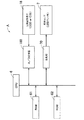
図1は、本発明の実施の一形態である画像読取装置1を備えた画像形成装置Aの構成を示す縦断面図である。図1に示すように、画像読取装置(画像読取部)1は、透明ガラスからなる原稿載置台11、原稿を自動的に供給しながら原稿画像を読取らせるための両面対応自動原稿送り装置(RADF)12、原稿載置台11上に載置された原稿の画像を走査して読み取るための原稿読取装置、すなわち原稿スキャナユニット13から構成されている。
FIG. 1 is a longitudinal sectional view showing a configuration of an image forming apparatus A including an image reading apparatus 1 according to an embodiment of the present invention. As shown in FIG. 1, an image reading device (image reading unit) 1 includes a document placing table 11 made of transparent glass, and a double-sided automatic document feeder for reading a document image while automatically supplying a document. RADF) 12, a document reading device for scanning and reading an image of a document placed on the document placement table 11, that is, a
前記RADF12は、所定の原稿トレイ上に複数枚の原稿を一度にセットしておき、セットされた原稿を1枚ずつ自動的に前記スキャナユニット13の原稿載置台11上の自動送り原稿の読取部へ送給する公知の装置である。そして、RADF12は、使用者の選択に応じて原稿の片面または両面をスキャナユニット13に読み取らせるように、片面原稿のための搬送経路、両面原稿のための搬送経路、搬送経路切り換え手段などから構成されている。このRADF12を用いて原稿画像の読取を行わせる場合は、原稿スキャナユニット13を構成する第1走査ユニット15および第2走査ユニット16(いずれも、後記する)は、原稿載置台11上の一側部に設けられた自動送り原稿の読取部に静止され、この自動送り原稿の読取部を通過する原稿の画像が逐次読取られる。図1は、第1走査ユニット15および第2走査ユニット16が、自動送り原稿の読取部に静止している状態を示している。RADF12は、原稿載置台11の上に開閉自在に設置された原稿カバー14に一体もしくは別体に設けられている。原稿カバー14は、原稿載置台11の上に置かれた原稿を押付けその浮き上がりを防止するべく使用され、その上面は自動送りされる原稿の排出トレイ140とされている。
The RADF 12 sets a plurality of documents at once on a predetermined document tray, and automatically loads the set documents one by one on the document placing table 11 of the
前記スキャナユニット13は、原稿面上を露光するランプリフレクタアセンブリと、原稿からの反射光像を電気的画像信号に変換する画像検出手段としての光電変換素子(たとえば、電荷結合素子(CCD)または密着型イメージセンサ(CIS))18に導くための第1反射ミラーを搭載した第1走査ユニット15および第2、第3反射ミラーを搭載した第2走査ユニット16、反射光像を光電変換素子18上に結像するための光学レンズ体17から構成される。第1走査ユニット15は、後記する原稿照射用光源7を搭載し、原稿載置台11に沿って図1の左から右へ一定速度Vで走行し、第2走査ユニット16は1/2Vの速度で同一方向に走行するように走査制御される。これにより、画像読取部1では、原稿載置台11上に読み取るべき原稿を順次載置させながら、原稿載置台11の下面に沿ってスキャナユニット13を移動させ、原稿載置台11上に載置された原稿の画像を1ライン毎に順次光電変換素子18に結像させて、原稿画像を読み取る。
The
原稿画像をスキャナユニット13で読み取ることにより得られた画像データは、各種処理が施された後、メモリに一旦記憶され、出力指示に応じてメモリから画像データを画像記録部2に出力して、感光体ドラム22上に可視画像として再現した後、用紙(記録媒体)上に画像を転写してトナー像を形成する。この画像記録部2は、レーザ書き込みユニット(LSU)21および画像を形成するための電子写真プロセス部20を備えている。レーザ書き込みユニット21は、メモリから読み出した画像データまたはパーソナルコンピュータ等の外部機器から転送されてきた画像データに応じてレーザ光を出射する半導体レーザ、レーザ光を等角速度偏向するポリゴンミラー、等角速度偏向されたレーザ光が電子写真プロセス部20の感光体ドラム22上を等速度で走査するように補正するf−θレンズ等を有している。電子写真プロセス部20は、周知の態様に従い、感光体ドラム22の周囲に帯電装置23、現像装置24、転写装置25、クリーニング装置26を配置し、さらに感光体ドラム22の下流側に定着装置27を配置して構成される。
The image data obtained by reading the document image with the
給紙部(記録媒体供給部)3は、多数枚の記録用紙をスタックし得る第1〜3カセット31〜33および手差しトレイ35を有している。これら第1〜3カセット31〜33および手差しトレイ35の給紙側前端部には、スタックされた用紙の最上層紙を1枚ずつ繰出すピックアップローラ31a〜33a、35aが設置され、その給紙方向下流側に近接して給紙ローラ31b〜33b、35bが、それぞれ設置されている。各給紙ローラ31b〜33b、35bの給紙方向下流側は合流して給紙搬送部4を構成し、この給紙搬送部4には、搬送ローラ41,42,43,44およびレジストローラ45が配設され、前記第1〜3カセット31〜33および手差しトレイ35から繰出された用紙は、搬送ローラ41,42,43のいずれかを経て、搬送ローラ44からレジストローラ45に至り、このレジストローラ45によりレジストされて、感光体ドラム22と転写装置25との間の転写位置に搬送導入される。
The paper feed unit (recording medium supply unit) 3 includes first to
なお、図1では、2点鎖線で示すように、第3カセット33の下にオプションとして大容量カセット34が、第4のカセットとして設置されており、前記給紙搬送部4はこの大容量カセット34の給紙側にも連接され、大容量カセット34から繰出された用紙は搬送ローラ41によって、前記転写位置に向け搬送される。すなわち、この給紙部3における第1〜4カセット31〜34内の4つのトレイには、用紙がサイズ毎に積載されて収容されており、ユーザーが所望するサイズの用紙が収容されているカセットあるいは前記手差しトレイ35を選択すると、あるいは、記録される画像データのサイズ情報に基づき自動選択されると、選択されたトレイ内の用紙束の上から1枚ずつ繰出され、給紙搬送部4の搬送経路を経由して順次電子写真プロセス部20へ向けて搬送される。給紙搬送部4の搬送経路は、前記転写位置を経て定着装置27に通じ、定着装置27の用紙搬送方向下流側には用紙排出路5が設けられている。
In FIG. 1, as indicated by a two-dot chain line, a large-
レーザ書き込みユニット21および電子写真プロセス部20において、メモリから読み出された画像データ、あるいは、パーソナルコンピュータ等の外部機器から転送されてきた画像データは、レーザ書き込みユニット21によってレーザ光線を走査させることにより感光体ドラム22の表面上に静電潜像として形成され、現像装置24のトナーにより可視像化されたトナー像は給紙部3から給紙搬送された用紙の表面上に転写装置25により静電転写され、定着装置27によって定着される。このようにして画像が形成された用紙は、前記定着装置27から前記用紙排出路5に設けられた搬送ローラ51および正逆回転可能な排出ローラ52を経て積載トレイ50へ送られる。搬送ローラ51と排出ローラ52との間の用紙排出路5には切換えゲート53が設けられ、この切換えゲート53の設置部分を基点として、前記搬送ローラ44の上流側で前記給紙搬送部4に合流する再給紙搬送部54が連接されている。
In the
画像が記録された用紙は、定着装置27を経て搬送ローラ51によりさらに上方に搬送され、切換えゲート53を通過する。そして、用紙の搬送先が前記積載トレイ50に設定されている場合は、排出ローラ52の正回転により積載トレイ50に排出される。一方、両面画像形成や後処理が指定されている場合には、一旦排出ローラ52により積載トレイ50に向けて用紙を排出する。なお、この場合には、用紙を完全に排出せず、排出ローラ52を一旦停止させて用紙の後端を排出ローラ52に狭持させ、その後排出ローラ52を逆回転させる。これにより、用紙は逆方向、つまり両面画像形成や後処理の為に選択的に装着されている再給紙搬送部54の方向に、反転搬送される。このとき、切換えゲート53は、上向きから下向きに切換えられる。再給紙搬送部54の途中には、後処理(ステープル、パンチングなど)のための切換えゲート55が設けられており、後処理モードが選択されたときには、この切換えゲート55の切換えにより、反転搬送された用紙は後処理部に送られ、ステープルやパンチング処理が施された後、後処理トレイ56上に排出される。両面画像記録を行なう場合は、反転搬送された用紙は再給紙搬送部54を通り、途中に配された搬送ローラ57,58,59によって搬送され、再びレジストローラ45を経て画像記録部2の前記転写位置に供給され、その裏面に対する画像記録がなされる。
The sheet on which the image is recorded is conveyed further upward by the conveying
図2は本発明の画像形成装置Aの制御ブロック図である。本実施形態の画像形成装置Aは、CPU6、RAM61、ROM62、画像読取部1を構成する照明ランプ(原稿照射用光源)7およびその駆動部(駆動回路)70、CCDあるいはCIS(密着型イメージセンサ)などの光電変換素子18からなる画像検出手段および検出したアナログデータをデジタル変換するA/D変換器180、図示しない、各駆動回路(画像読取部1の他の駆動回路、前記各搬送ローラ等を含む用紙搬送系の駆動回路、画像記録部2の駆動回路など)、操作パネルコントローラ、操作パネルおよび各種検出センサなどを備えている。本画像形成装置Aがファクシミリ機能やプリンタ機能も備えたいわゆる複合機である場合には、ファクシミリエンジンやプリンタコントローラなども装備される。CPU6は、本画像形成装置Aの動作全体の制御を司る中枢の制御手段である。RAM61は、CPU6のワーキングエリアとして使用される。ROM62は、CPU6に実行させるためのプログラムを格納している。
FIG. 2 is a control block diagram of the image forming apparatus A of the present invention. The image forming apparatus A according to the present embodiment includes a
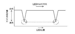
図3は、画像読取部1の原稿照明部の概略構成を示す図であり、照明ランプ7として、原稿載置台11の下に配置され、アレイ基板71上に主走査方向に沿って多数の点光源用発光素子(たとえば、白色LED等)72…を配列した点光源アレイ(たとえば、LEDアレイ等)を用いた例を示している。この照明ランプ7は、図4に示すように、多数の白色LED72が長尺のアレイ基板71にその長手方向に沿って一列に配列されたものであり、アレイの長手方向の全長Lは原稿載置台11の幅方向の長さ(図1における原稿載置台11の左端の原稿基準スケールの長さ)と同じかそれ以上の長さに設定されている。図3は、後記するように、原稿載置台11の上に原稿Dを置き、その原稿画像の読取動作に先立ち、プレスキャンして原稿Dの主走査方向幅を判別する要領を示している。すなわち、原稿載置台11の上に原稿Dを画像面を下向きにして置き、原稿カバー14を閉じた状態で、照明ランプ7のLED72を順次点灯させ、原稿Dに照射させてゆく。原稿Dの端部では、照射光の影DSが原稿カバー14のカバー面に生じる。前記光電変換素子18はこの影DSを検出し、前記CPU6はこの影DSの検出情報に基づき、原稿Dの端部として認識して原稿Dの主走査方向のサイズを判別する。図3では、クロスハッチングを付したLED72は消灯中、白抜きしたLED72は点灯中であることを示している。また、LED72は、原稿Dに対して斜めに光が照射されるよう配置されている。
FIG. 3 is a diagram illustrating a schematic configuration of the document illumination unit of the image reading unit 1. The
図3に示すように、照明ランプ7のLED72を矢符73に示す方向に順次点灯させてゆくと、原稿Dの影DSでなければ、LED72の発光特性により、点灯しているLED72から離れた位置の明るさが決定されるが、原稿Dがある部分は影DSができて、LED72の発光特性より暗い部分が発生する。画像データの場合は、照射角によって濃度は変わらないため近接するLED72による画像で原稿D上の画像か原稿Dの端部の影かの判別が可能となる。また、前記のようにLED72を点灯して画像を取得する際、LED72の数量と同じ回数画像データを取得するのではなく、互いに影響しない程度はなれたLED72は同時に点灯させて、取得する画像データの数を最小限にすることが望ましい。
As shown in FIG. 3, when the
図6は、前記のようにプレスキャンさせながら原稿Dの両端(2箇所)を認識するプロセスのフロー図を示している。ステップS1では、原稿Dが原稿載置台11の上に置かれ、原稿カバー14が閉められたことを検出する。原稿カバー14が閉じているか否かは、公知の検出技術で検出することができる。
FIG. 6 shows a flowchart of a process for recognizing both ends (two places) of the document D while pre-scanning as described above. In step S1, it is detected that the document D is placed on the document table 11 and the
ステップS2にて、図3に示すような位置関係で白色LED72を一つ点灯して原稿Dを照明する。その時の反射光を認識し、原稿端の影があるかどうかを判断する(ステップS3)。原稿端の影が無い場合は、次の白色LED72を点灯し、ステップS2に戻る。原稿端の影がある場合は、その位置を記憶し、ステップS4へ進む。ステップS4では、ステップS3にて原稿端の影を認識した次の白色LED72を点灯し、ステップS2と同様に白色LED72を一つ点灯して原稿Dを照明する。その時の反射光を認識し、原稿端の影があるかどうかを判断する(ステップS5)。原稿端の影が無い場合は、次の白色LED72を点灯し、ステップS4に戻る。原稿端の影がある場合は、その位置を記憶し、終了する。上記ステップS3、ステップS5にて認識した各位置の距離が原稿の大きさとなる。
In step S2, one
前記のように、白色LED72を端から順次一個づつ、原稿の画像読み取り面に対して斜め方向から照射し、その状態を光電変換素子18(CCDまたはCIS)にて読み込むと、原稿カバー14のカバー面、および、原稿Dの部分では、白色に近い電気信号レベルが得られるが、図3のように、原稿端に白色LED72からの光を斜めに照射すると影DSが発生し、それを光電変換素子18にて読み込むと、原稿端の位置だけ影のため黒色に近い電気信号が得られる。図5は、白色LED72を順次点灯することにより原稿Dで反射した光の光電変換素子18による電気信号レベルの変化を示しており、横軸は主走査方向に沿った白色LED72の位置を、縦軸は電気信号レベルをそれぞれ示している。図5のようにグラフのくさび型の部分が原稿端になり、CPU6は、その2箇所の距離を、幅方向(主走査方向)の原稿サイズとして検知判別する。このように、原稿Dの幅方向両端部を検知してその原稿サイズを判別するから、原稿Dが定形紙、不定形紙に関係なく、原稿サイズの判別が的確になされる。また、原稿Dが基準位置からずれて置かれても、そのサイズの判別がなされる。
As described above, when the
主走査方向の原稿サイズ検知判別後は、照明ランプ7内の主走査方向の原稿幅領域における白色LED72を点灯させた状態で、前記原稿スキャナユニット13における第1走査ユニット15および第2走査ユニット16を副走査方向に走行させて、原稿載置台11上の原稿Dの画像を読取る。図7はこの画像読取の状態を示しており、照明ランプ7は紙面に垂直方向に走行する。図7において、図3の場合と同様にクロスハッチングを付した白色LED72は消灯状態を、白抜きの白色LED72は点灯状態を示し、照明ランプ7は、この状態で副走査方向に走行しながら原稿Dの画像面を照明し、その反射光画像が光電変換素子18に結像され、原稿画像の読取がなされる。
After the determination of the document size detection in the main scanning direction, the
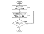
そして、この画像読取操作と並行して、原稿Dの副走査方向のサイズが判別される。図8は、副走査方向の原稿Dの大きさを認識するプロセスのフロー図を示している。前記主走査方向の原稿サイズの認識判別が完了した(ステップS11)後、ステップS12において、図7に示すように、照明ランプ7内の白色LED72を前記判別した主走査方向の原稿幅領域に相当する部分だけ点灯させた状態で、前記第1走査ユニット15および第2走査ユニット16を前記走行パターン(走行速度Vおよび1/2V)で副走査方向に走行移動させ、この走行移動の間に原稿面を走査し、光電変換素子18によって反射光に基づく原稿画像を読み取る。読取られた原稿画像において、副走査方向の終端部が認識出来れば(ステップS13)、その位置を記憶し、終了する。この位置が副走査方向の原稿Dのサイズとなる。この終端部の認識は、図3に示したと同様に、原稿端部による影DSの認識によってなされる。
In parallel with this image reading operation, the size of the document D in the sub-scanning direction is determined. FIG. 8 shows a flowchart of a process for recognizing the size of the document D in the sub-scanning direction. After completion of the recognition of the document size in the main scanning direction (step S11), in step S12, as shown in FIG. 7, the
前記動作のように主走査方向の原稿Dの幅(サイズ)を判別した上で、原稿Dの主走査方向のサイズに合った個数の白色LED72を点灯し、原稿Dの画像を読み取ることより、全ての白色LED72を点灯する場合に比べて消費電力の節約がなされ、また、白色LED72の寿命を延ばすことが可能となる。また、上記動作にて、原稿Dの主走査方向両端間のサイズが信号レベルで認識できるため、原稿Dが基準端からずれていた場合でも、原稿端に対する出力信号間の距離で原稿Dの主走査方向のサイズを検知することが可能となる。
By discriminating the width (size) of the document D in the main scanning direction as described above, the number of
なお、例示の実施形態では、書き込みユニット21がレーザ方式によるものを示したが、LED(発光ダイオード)方式であっても良い。また、照明ランプ7を構成する発光素子として白色LEDを例示したが、他の発光素子であっても良い。さらに、図1に示す画像読取装置1におけるRADF12は、原稿を自動供給しながら、静止中の原稿スキャナユニット13によって原稿画像を読取るタイプであるが、ADFにより自動供給された原稿を一旦原稿載置台11の上に静止させ、その下で原稿スキャナユニット13を走行移動させることによって原稿画像を読取るタイプのものであっても良い。加えて、本発明の画像読取装置は、スキャナ専用機、送信専用ファクシミリ装置のように画像記録部を有さない画像形成装置にも適用することができる。この場合、原稿サイズの判別情報は、これらと接続されるパーソナルコンピュータやファクシミリ受信機に対して有用な情報となる。
In the illustrated embodiment, the
1 画像読取装置
2 画像記録部
3 記録媒体供給部
6 制御手段
7 原稿照射用光源
11 原稿載置台
13 原稿スキャナユニット
14 原稿カバー
18 光電変換素子
72 発光素子
A 画像形成装置
D 原稿
DS 原稿端部による影
DESCRIPTION OF SYMBOLS 1
Claims (6)
前記原稿スキャナユニットは、主走査方向に複数の発光素子を配列した原稿照射用光源と、前記光源による原稿からの反射光を検出する画像検出手段とを備え、
前記制御手段は、
前記原稿カバーを閉じた状態で、
前記複数の発光素子を順次点灯させ、前記画像検出手段により、前記原稿載置台上の原稿端部の影の部分を検知することで、前記原稿載置台上の主走査方向の原稿サイズを判別することを特徴とする原稿読取装置。 In a document reading apparatus, comprising: a transparent document placing table; a document cover that can be freely opened and closed on the document placing table; a document scanner unit that is disposed at a lower portion of the document placing table; and a control unit.
The document scanner unit includes a document irradiation light source in which a plurality of light emitting elements are arranged in a main scanning direction, and an image detection unit that detects reflected light from the document by the light source,
The control means includes
With the document cover closed,
The plurality of light emitting elements are sequentially turned on, and the image detecting unit detects a shadow portion at the edge of the document on the document table, thereby determining the document size in the main scanning direction on the document table. An original reading apparatus characterized by the above.
Priority Applications (1)
| Application Number | Priority Date | Filing Date | Title |
|---|---|---|---|
| JP2008319009A JP2010141856A (en) | 2008-12-15 | 2008-12-15 | Manuscript reading device and image forming device using the same |
Applications Claiming Priority (1)
| Application Number | Priority Date | Filing Date | Title |
|---|---|---|---|
| JP2008319009A JP2010141856A (en) | 2008-12-15 | 2008-12-15 | Manuscript reading device and image forming device using the same |
Publications (1)
| Publication Number | Publication Date |
|---|---|
| JP2010141856A true JP2010141856A (en) | 2010-06-24 |
Family
ID=42351532
Family Applications (1)
| Application Number | Title | Priority Date | Filing Date |
|---|---|---|---|
| JP2008319009A Pending JP2010141856A (en) | 2008-12-15 | 2008-12-15 | Manuscript reading device and image forming device using the same |
Country Status (1)
| Country | Link |
|---|---|
| JP (1) | JP2010141856A (en) |
Cited By (7)
| Publication number | Priority date | Publication date | Assignee | Title |
|---|---|---|---|---|
| JP2013005284A (en) * | 2011-06-17 | 2013-01-07 | Kyocera Document Solutions Inc | Image reading device and image formation device incorporating the same |
| JP2014064168A (en) * | 2012-09-21 | 2014-04-10 | Kyocera Document Solutions Inc | Image forming apparatus |
| JP2014064169A (en) * | 2012-09-21 | 2014-04-10 | Kyocera Document Solutions Inc | Image forming apparatus |
| JP2014064167A (en) * | 2012-09-21 | 2014-04-10 | Kyocera Document Solutions Inc | Image forming apparatus |
| JP2015053711A (en) * | 2014-10-24 | 2015-03-19 | 京セラドキュメントソリューションズ株式会社 | Document reading apparatus |
| JP2015053713A (en) * | 2014-10-24 | 2015-03-19 | 京セラドキュメントソリューションズ株式会社 | Document reading apparatus |
| JP2015053712A (en) * | 2014-10-24 | 2015-03-19 | 京セラドキュメントソリューションズ株式会社 | Document reading apparatus |
-
2008
- 2008-12-15 JP JP2008319009A patent/JP2010141856A/en active Pending
Cited By (7)
| Publication number | Priority date | Publication date | Assignee | Title |
|---|---|---|---|---|
| JP2013005284A (en) * | 2011-06-17 | 2013-01-07 | Kyocera Document Solutions Inc | Image reading device and image formation device incorporating the same |
| JP2014064168A (en) * | 2012-09-21 | 2014-04-10 | Kyocera Document Solutions Inc | Image forming apparatus |
| JP2014064169A (en) * | 2012-09-21 | 2014-04-10 | Kyocera Document Solutions Inc | Image forming apparatus |
| JP2014064167A (en) * | 2012-09-21 | 2014-04-10 | Kyocera Document Solutions Inc | Image forming apparatus |
| JP2015053711A (en) * | 2014-10-24 | 2015-03-19 | 京セラドキュメントソリューションズ株式会社 | Document reading apparatus |
| JP2015053713A (en) * | 2014-10-24 | 2015-03-19 | 京セラドキュメントソリューションズ株式会社 | Document reading apparatus |
| JP2015053712A (en) * | 2014-10-24 | 2015-03-19 | 京セラドキュメントソリューションズ株式会社 | Document reading apparatus |
Similar Documents
| Publication | Publication Date | Title |
|---|---|---|
| JP4157832B2 (en) | Document size detection method, document reading apparatus, and image forming apparatus | |
| JP5316260B2 (en) | Document reading apparatus and size determination method | |
| JP4568773B2 (en) | Document reading apparatus and image forming apparatus | |
| JP2010141856A (en) | Manuscript reading device and image forming device using the same | |
| JP2008147816A (en) | Image reader | |
| JP5760684B2 (en) | Image reading apparatus and image forming apparatus | |
| JP2020061672A (en) | Document size detection device, image reading device, image forming apparatus, and document size detection method | |
| JP2014060550A (en) | Document reading device, image forming apparatus, document reading method, and program | |
| US7548353B2 (en) | Image reading apparatus and image reading method | |
| JP5747662B2 (en) | Image reading apparatus and image forming apparatus | |
| JP2010141857A (en) | Original reading apparatus and image forming apparatus using the same | |
| US20150181051A1 (en) | Image reading apparatus, image forming apparatus, document sheet width detecting method | |
| JP2004328154A (en) | Original reading apparatus and original reading method | |
| US11671544B2 (en) | Image reading apparatus, image forming apparatus, and document size detection method | |
| JP4920088B2 (en) | Illumination apparatus, image reading apparatus including the illumination apparatus, and image forming apparatus including the image reading apparatus | |
| JP2012119868A (en) | Image reading device, and image forming apparatus | |
| JP2011259164A (en) | Image reading device and image formation device | |
| JP2009118377A (en) | Image reading device and image forming apparatus equipped with it | |
| JP6063350B2 (en) | Image reading apparatus and image forming apparatus | |
| JP7196541B2 (en) | Image reading device and image forming device | |
| JP4988679B2 (en) | Image reading apparatus and image forming apparatus | |
| JP6488676B2 (en) | Image reading apparatus, automatic document feeder, image forming apparatus, and facsimile apparatus | |
| JP4132473B2 (en) | Image processing apparatus and image forming apparatus | |
| JP2008060867A (en) | Document reader | |
| JP2007013907A (en) | Image reading apparatus, and image forming apparatus |