JP2010141844A - Transmission device - Google Patents
Transmission device Download PDFInfo
- Publication number
- JP2010141844A JP2010141844A JP2008318912A JP2008318912A JP2010141844A JP 2010141844 A JP2010141844 A JP 2010141844A JP 2008318912 A JP2008318912 A JP 2008318912A JP 2008318912 A JP2008318912 A JP 2008318912A JP 2010141844 A JP2010141844 A JP 2010141844A
- Authority
- JP
- Japan
- Prior art keywords
- transmission
- unit
- electrode
- radio frequency
- signal line
- Prior art date
- Legal status (The legal status is an assumption and is not a legal conclusion. Google has not performed a legal analysis and makes no representation as to the accuracy of the status listed.)
- Withdrawn
Links
- 230000005540 biological transmission Effects 0.000 title claims abstract description 99
- 230000006870 function Effects 0.000 claims description 8
- 230000007246 mechanism Effects 0.000 claims description 3
- 238000001514 detection method Methods 0.000 claims 1
- 230000005236 sound signal Effects 0.000 abstract description 18
- 239000003990 capacitor Substances 0.000 abstract description 9
- 230000002238 attenuated effect Effects 0.000 abstract description 5
- 238000000034 method Methods 0.000 description 7
- 238000010586 diagram Methods 0.000 description 6
- 230000008569 process Effects 0.000 description 3
- 239000000470 constituent Substances 0.000 description 2
- 238000005259 measurement Methods 0.000 description 2
- 230000004044 response Effects 0.000 description 2
- 238000012986 modification Methods 0.000 description 1
- 230000004048 modification Effects 0.000 description 1
- 238000012545 processing Methods 0.000 description 1
Images


Landscapes
- Details Of Aerials (AREA)
- Transmitters (AREA)
Abstract
Description
この発明は、例えばFM(Frequency Modulation)波などを利用して、再生装置から出力される音声信号などを無線送信するのに用いられる送信装置に関する。 The present invention relates to a transmission device used to wirelessly transmit an audio signal or the like output from a playback device using, for example, an FM (Frequency Modulation) wave.
周知のように、従来の送信装置は、例えばHDD(Hard Disk Drive)やフラッシュメモリに音楽データや映像データを蓄積した再生装置に接続したり、あるいは再生装置に備えられ、音声信号をFM波で無線送信する。そして、FM波をカーラジオなどで受信して、拡声出力させる。 As is well known, a conventional transmission device is connected to a playback device that stores music data or video data in, for example, an HDD (Hard Disk Drive) or a flash memory, or is provided in the playback device, and an audio signal is transmitted using an FM wave. Wireless transmission. Then, the FM wave is received by a car radio or the like and outputted as a loud voice.
また送信装置が再生装置に備えられる場合、イヤホン端子に接続されるイヤホンのコードをアンテナとして利用することで、安定した送信を行えるようにしている。アンテナとして利用されるイヤホンコードは、できるだけまっすぐに延ばした状態で用いられることが望ましい。なお、日本国内においては、FM波の送信電力は、所定の限界強度内に制限されており、これを遵守するために、最良の状態にイヤホンコードを設置した状態で送信出力が設定される。 When the transmission device is provided in the playback device, the earphone cord connected to the earphone terminal is used as an antenna so that stable transmission can be performed. It is desirable that the earphone cord used as an antenna be used as straight as possible. In Japan, the transmission power of FM waves is limited within a predetermined limit intensity, and in order to comply with this, the transmission output is set with the earphone cord set in the best condition.
しかしながら、実際には、ユーザがイヤホンコードはまっすぐに延ばして利用することは少なく、受信装置でFM波が十分な受信電力で受信できず、再生音に雑音が混ざってしまうことがあった。特に、車載ラジオを利用する場合には、車内から送信したFM波を車外のアンテナで受信する場合に、このような不具合が顕著となる。 However, in practice, the user rarely uses the earphone cord by extending it straight, and the receiving apparatus cannot receive the FM wave with sufficient reception power, and noise may be mixed with the reproduced sound. In particular, when using an in-vehicle radio, such a problem becomes remarkable when an FM wave transmitted from the inside of the vehicle is received by an antenna outside the vehicle.
これに対して従来は、使用環境の影響を受けがたい送信方法などが考えられていた(例えば、特許文献1)。しかしながら、この文献に記される手法では、アンテナケーブルの這わせ方などの条件が多く、ユーザへの負担が大きいという問題があった。
従来の送信装置では、使用環境に応じたユーザ設定に手間がかかり、手軽に高品位な送信が行えないという問題があった。
この発明は上記の問題を解決すべくなされたもので、ユーザに特別な知識が無くても、簡単な操作で手軽に高品位な送信を行うことが可能な送信装置を提供することを目的とする。
The conventional transmission apparatus has a problem that it takes time to set the user according to the use environment, and high-quality transmission cannot be easily performed.
The present invention has been made to solve the above-described problem, and an object thereof is to provide a transmission device capable of easily performing high-quality transmission with a simple operation without special knowledge for the user. To do.
上記の目的を達成するために、この発明は、再生信号を出力するための信号ラインに接続される第1接点と、インダクタを介してグランドに接続される第2接点と、第2接点に接続される信号ラインがアンテナとして機能する外部装置が物理的に着脱自在な機構とを備える着脱手段と、第2接点に無線周波信号を供給する送信手段と、信号ラインとグランドの間に設けられたハイパスフィルタとを具備して構成するようにした。 To achieve the above object, the present invention provides a first contact connected to a signal line for outputting a reproduction signal, a second contact connected to ground via an inductor, and a second contact. The signal line is provided between the signal line and the ground, the detachable means having a mechanism in which the external device that functions as an antenna is physically detachable, the transmission means for supplying the second contact with the radio frequency signal, A high-pass filter is provided.
以上述べたように、この発明では、第2接点を通じて無線周波信号を外部装置に出力し、外部装置から第1接点を介して信号ラインに戻る無線周波信号をハイパスフィルタを介してグランドするようにしている。 As described above, in the present invention, the radio frequency signal is output to the external device through the second contact, and the radio frequency signal returning from the external device to the signal line through the first contact is grounded through the high-pass filter. ing.
したがって、この発明によれば、イヤホンのような外部装置の場合には、無線周波信号が信号ラインに戻ってグランドされ減衰し、一方、アンテナのような外部装置の場合には、無線周波信号が信号ラインに戻らず減衰しない。このため、ユーザに特別な知識が無くても、ユーザは接続する外部装置を選択するという簡単な操作で、無線周波信号の送信効率を切り替えられ、手軽に高品位な送信を行うことが可能な送信装置を提供できる。 Therefore, according to the present invention, in the case of an external device such as an earphone, the radio frequency signal returns to the signal line and is grounded and attenuated, whereas in the case of an external device such as an antenna, the radio frequency signal is Does not return to the signal line and does not attenuate. For this reason, even if there is no special knowledge for the user, the user can switch the transmission efficiency of the radio frequency signal with a simple operation of selecting an external device to be connected, and can easily perform high-quality transmission. A transmission device can be provided.
以下、図面を参照して、この発明の一実施形態について説明する。
(第1の実施形態)
図1は、この発明の第1の実施形態に係わる送信装置の構成を示すものである。この送信装置は、イヤホンジャックJと、再生部10と、送信部20と、制御部31と、コンデンサC1、C2と、インダクタンスL1とを備えている。
Hereinafter, an embodiment of the present invention will be described with reference to the drawings.
(First embodiment)
FIG. 1 shows the configuration of a transmission apparatus according to the first embodiment of the present invention. This transmission device includes an earphone jack J, a
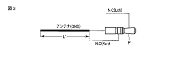
イヤホンジャックJは、図2に示すような2チャンネル3極のイヤホンのプラグPと電気的および物理的に接続するものであって、プラグPのGNDと接続するための電極Tgと、右スピーカSP1のプラス極に接続されるプラグPの電極と接続するための電極Trと、左スピーカSP2のプラス極に接続されるプラグPの電極と接続するための電極Tlと、プラグPが接続されたことを検出するための電極Tpを備える。なお、図2に示すイヤホンのスピーカSP1、SP2は、それぞれ16〜32Ω程度のインピーダンスZsを有し、GND線がFM波を送信するためのアンテナとして機能する。 The earphone jack J is electrically and physically connected to a plug P of a two-channel three-pole earphone as shown in FIG. The plug Tr is connected to the electrode Tr for connecting to the electrode of the plug P connected to the positive pole of the electrode, the electrode Tl for connecting to the electrode of the plug P connected to the positive pole of the left speaker SP2. The electrode Tp for detecting is provided. The earphone speakers SP1 and SP2 shown in FIG. 2 each have an impedance Zs of about 16 to 32Ω, and the GND line functions as an antenna for transmitting FM waves.
再生部10は、制御部31によって制御され、図示しない記憶部からMP3(MPEG Audio Layer-3)などの符号化方式により符号化された音楽データなどを読み出して復号して、この復号結果に基づくアナログ音声信号を出力する。このアナログ音声信号は、左右のチャンネルRch、Lchの2チャンネルの信号であり、チャンネルRchの信号は、電極Trに出力され、一方、チャンネルLchの信号は、電極Trに出力される。またチャンネルRchの信号ラインとGNDの間には、コンデンサC1が設けられ、同様に、チャンネルLchの信号ラインとGNDの間には、コンデンサC2が設けられる。各コンデンサは、ハイパスフィルタとして機能するように、送信部20で生成される無線周波信号の周波数に応じた容量となっている。
The
送信部20は、制御部31によって制御され、チャンネルRch、Lchのアナログ音声信号を用いてFM変調の無線周波信号を生成する。この無線周波信号は、イヤホンジャックJの電極Tgに出力される。なお、無線周波信号のラインと、GNDの間には、インダクタンスL1が設けられる。
The
制御部31は、当該送信装置の各部を統括して制御するものであって、図示しないユーザインタフェースを通じたユーザからの指示に応じて、再生部10に対して音楽データを復号するように指示したり、あるいは、再生部10が出力するアナログ音声信号をFM波で送信するように送信部20を制御する。
The
また制御部31は、イヤホンジャックJとプラグPが接続されたことを、電極Tlと電極Tpとが導通することにより検出する。すなわち、電極Tlと電極Tpは、イヤホンジャックJとプラグPが接続された場合に、プラグPの先端部によって導通状態となる。そして、制御部31は、イヤホンジャックJとプラグPとが接続される場合にのみ、送信部20が無線周波信号を生成するように制御する。
Further, the
次に、上記構成の送信装置の動作について説明する。
まず、図2に示すようなイヤホンが接続される場合について説明する。ユーザがイヤホンのプラグPをジャックJに接続し、図示しないユーザインタフェースを通じて音楽の再生要求とFM波の送信要求を行うと、制御部31は、再生部10に音楽データの復号を開始するように指示し、そして電極Tlと電極Tpとが導通状態になっていることを検出し、これにより送信部20を起動する。これにより、再生部10は、アナログ音声信号の出力を開始し、送信部20は、無線周波信号の生成を開始する。
Next, the operation of the transmission apparatus having the above configuration will be described.
First, a case where an earphone as shown in FIG. 2 is connected will be described. When the user connects the earphone plug P to the jack J and makes a music playback request and FM wave transmission request through a user interface (not shown), the
また、イヤホンのプラグPがジャックJに接続されることにより、スピーカSP1、SP2のマイナス極がプラグPおよびジャックJの電極Tgを通じて、送信装置のGNDに接続される。そして右スピーカSP1のプラス極には、電極TrおよびプラグPを通じて、チャンネルRchの信号が入力され、これにより右スピーカSP1から右チャネルの音声が拡声出力される。同様にして、左スピーカSP2のプラス極には、電極TlおよびプラグPを通じて、チャンネルLchの信号が入力され、これにより左スピーカSP2から左チャネルの音声が拡声出力される。 Further, when the plug P of the earphone is connected to the jack J, the negative poles of the speakers SP1 and SP2 are connected to the GND of the transmitting device through the plug P and the electrode Tg of the jack J. Then, the channel Rch signal is input to the positive pole of the right speaker SP1 through the electrode Tr and the plug P, whereby the right channel sound is amplified from the right speaker SP1. Similarly, the channel Lch signal is input to the positive pole of the left speaker SP2 through the electrode Tl and the plug P, and thereby the left channel sound is amplified from the left speaker SP2.
そしてまた、送信部20から出力された無線周波信号は、ジャックJの電極TgおよびプラグPを通じて、イヤホンのGNDラインに出力される。これにより、上記無線周波信号は、イヤホンのGNDラインから空間に放射される。なお、GNDラインは、インピーダンスZsをそれぞれ有するスピーカSP1、SP2およびコンデンサC1、C2を介して、送信装置のGNDに接続されているため、上記無線周波信号は減衰する。
The radio frequency signal output from the
次に、図3に示す小型アンテナAが接続される場合について説明する。小型アンテナAは、プラグPと、アンテナとして機能するGNDラインを備える。GNDラインは、長さL1を有し、イヤホンジャックJとの接続により、電極Tgと電気的に接続される。また、イヤホンジャックJの電極Trと接続されるプラグPの電極は、何も接続されていない。同様に、イヤホンジャックJの電極Tlと接続されるプラグPの電極は、何も接続されていない。 Next, the case where the small antenna A shown in FIG. 3 is connected will be described. The small antenna A includes a plug P and a GND line that functions as an antenna. The GND line has a length L1 and is electrically connected to the electrode Tg through connection with the earphone jack J. Also, nothing is connected to the electrode of the plug P connected to the electrode Tr of the earphone jack J. Similarly, nothing is connected to the electrode of the plug P connected to the electrode Tl of the earphone jack J.
ユーザが小型アンテナAのプラグPをジャックJに接続し、図示しないユーザインタフェースを通じて音楽の再生要求とFM波の送信要求を行うと、制御部31は、再生部10に音楽データの復号を開始するように指示し、そして電極Tlと電極Tpとが導通状態になっていることを検出し、これにより送信部20を起動する。これにより、再生部10は、アナログ音声信号の出力を開始し、送信部20は、無線周波信号の生成を開始する。
When the user connects the plug P of the small antenna A to the jack J and makes a music playback request and FM wave transmission request through a user interface (not shown), the
また、小型アンテナAはスピーカを備えないことより、音声が拡声出力されない。しかし、送信部20から出力された無線周波信号が、ジャックJの電極TgおよびプラグPを通じて、小型アンテナAのGNDラインに出力される。これにより、上記無線周波信号は、小型アンテナAのGNDラインから空間に放射される。なお、小型アンテナAのGNDラインは、図2に示したイヤホンのように、送信装置のGNDに接続されていないため、無線周波信号が減衰することなく、上記GNDラインから放射される。
In addition, since the small antenna A does not include a speaker, no sound is output. However, the radio frequency signal output from the
以上のように、上記構成の送信装置では、図2に示したイヤホンをアンテナとして用いる場合には、送信部20が生成した無線周波信号はイヤホンのスピーカおよびコンデンサC1、C2を通じて減衰し、一方、小型アンテナAをアンテナとして用いる場合には、音声信号の出力端子が開放されることで、減衰しない。このため、小型アンテナAをアンテナとして用いた場合に、法令に定められる送信電力となるように、送信部20の出力を調整しておけばよい。
As described above, in the transmission apparatus configured as described above, when the earphone shown in FIG. 2 is used as an antenna, the radio frequency signal generated by the
したがって、上記構成の送信装置によれば、ユーザはFM波による送信を行いたい場合には、小型アンテナAを接続することで高品位な送信を行うことができ、一方、イヤホンを接続した場合には、小型アンテナAを用いた場合よりも、大きな送信電力で送信されることはないので、法令を遵守することができる。すなわち、ユーザに特別な知識が無くても、簡単な操作で手軽に高品位な送信を行うことができる。 Therefore, according to the transmission apparatus configured as described above, when the user wants to perform transmission using FM waves, the user can perform high-quality transmission by connecting the small antenna A, while the user can connect the earphone. Is not transmitted with a larger transmission power than when the small antenna A is used, so that it is possible to comply with laws and regulations. That is, even if the user has no special knowledge, high-quality transmission can be easily performed with a simple operation.
また、上記実施の形態では、イヤホンジャックJにプラグPが接続された場合に限って、制御部31が送信部20を起動するようにしているので、無駄に無線周波信号が生成されることを防止できる。
In the above embodiment, the
(第2の実施形態)
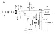
図4は、この発明の第2の実施形態に係わる送信装置の構成を示すものである。この送信装置は、イヤホンジャックJと、再生部10と、送信部20と、制御部32と、抵抗器R1、R2と、インダクタンスL1とを備えている。
(Second Embodiment)
FIG. 4 shows the configuration of a transmission apparatus according to the second embodiment of the present invention. This transmission device includes an earphone jack J, a
イヤホンジャックJは、図2に示すような2チャンネル3極のイヤホンのプラグPや、図3に示した小型アンテナA、図5に示す小型アンテナBあるいは図6に示す小型アンテナCと電気的および物理的に接続するものであって、プラグPのGNDと接続するための電極Tgと、右スピーカSP1のプラス極に接続されるプラグPの電極と接続するための電極Trと、左スピーカSP2のプラス極に接続されるプラグPの電極と接続するための電極Tlと、プラグPが接続されたことを検出するための電極Tpを備える。 The earphone jack J is electrically connected to the plug P of the two-channel three-pole earphone as shown in FIG. 2, the small antenna A shown in FIG. 3, the small antenna B shown in FIG. 5, or the small antenna C shown in FIG. The electrode Tg for connecting to the GND of the plug P, the electrode Tr for connecting to the electrode of the plug P connected to the positive pole of the right speaker SP1, and the left speaker SP2 An electrode Tl for connecting to the electrode of the plug P connected to the positive electrode and an electrode Tp for detecting that the plug P is connected are provided.
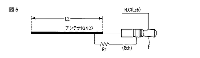
図5に示す小型アンテナBは、プラグPと、アンテナとして機能するGNDラインを備える。GNDラインは、長さL2(>L1)を有し、イヤホンジャックJとの接続により、電極Tgと電気的に接続される。また、イヤホンジャックJの電極Trと接続されるプラグPの電極は、インピーダンスRrの抵抗器を介して上記GNDラインに接続される。一方、イヤホンジャックJの電極Tlと接続されるプラグPの電極は、何も接続されていない。なお、インピーダンスRrは、インピーダンスZsと同程度である。 A small antenna B shown in FIG. 5 includes a plug P and a GND line that functions as an antenna. The GND line has a length L2 (> L1) and is electrically connected to the electrode Tg through connection with the earphone jack J. The electrode of the plug P connected to the electrode Tr of the earphone jack J is connected to the GND line via a resistor having an impedance Rr. On the other hand, nothing is connected to the electrode of the plug P connected to the electrode Tl of the earphone jack J. The impedance Rr is approximately the same as the impedance Zs.
図6に示す小型アンテナCは、プラグPと、アンテナとして機能するGNDラインを備える。GNDラインは、長さL3(>L2>L1)を有し、イヤホンジャックJとの接続により、電極Tgと電気的に接続される。また、イヤホンジャックJの電極Trと接続されるプラグPの電極は、何も接続されていない。一方、イヤホンジャックJの電極Tlと接続されるプラグPの電極は、インピーダンスRlの抵抗器を介して上記GNDラインに接続される。なお、インピーダンスRlは、インピーダンスZsと同程度である。 A small antenna C shown in FIG. 6 includes a plug P and a GND line that functions as an antenna. The GND line has a length L3 (> L2> L1) and is electrically connected to the electrode Tg through connection with the earphone jack J. Also, nothing is connected to the electrode of the plug P connected to the electrode Tr of the earphone jack J. On the other hand, the electrode of the plug P connected to the electrode Tl of the earphone jack J is connected to the GND line via a resistor having an impedance Rl. The impedance Rl is about the same as the impedance Zs.
再生部10は、制御部32によって制御され、図示しない記憶部からMP3(MPEG Audio Layer-3)などの符号化方式により符号化された音楽データなどを読み出して復号して、この復号結果に基づくアナログ音声信号を出力する。このアナログ音声信号は、左右のチャンネルRch、Lchの2チャンネルの信号であり、チャンネルRchの信号は、電極Trに出力され、一方、チャンネルLchの信号は、電極Tlに出力される。
The
またチャンネルRchの信号ラインと動作電圧Vccの間には、抵抗器R1が設けられ、同様に、チャンネルLchの信号ラインと動作電圧Vccの間には、抵抗器R2が設けられ、各信号ラインはプルアップされている。各抵抗器は、インピーダンスZsに比べて非常に大きな抵抗値(以下、R1、R2と称する)を有する。 In addition, a resistor R1 is provided between the signal line of the channel Rch and the operating voltage Vcc, and similarly, a resistor R2 is provided between the signal line of the channel Lch and the operating voltage Vcc. Pulled up. Each resistor has a very large resistance value (hereinafter referred to as R1 and R2) compared to the impedance Zs.
送信部20は、制御部32によって制御され、チャンネルRch、Lchのアナログ音声信号を用いてFM変調の無線周波信号を生成する。また送信部20は、制御部32から指示される電力の上記無線周波信号を生成する。この無線周波信号は、イヤホンジャックJの電極Tgに出力される。なお、無線周波信号のラインと、GNDの間には、インダクタンスL1が設けられる。
The
制御部32は、当該送信装置の各部を統括して制御するものであって、図示しないユーザインタフェースを通じたユーザからの指示に応じて、再生部10に対して音楽データを復号するように指示したり、あるいは、再生部10が出力するアナログ音声信号をFM波で送信するように送信部20を制御する。
The
また制御部32は、イヤホンジャックJとプラグPが接続されたことを、電極Tlと電極Tpとが導通することにより検出する。すなわち、電極Tlと電極Tpは、イヤホンジャックJとプラグPが接続された場合に、プラグPの先端部によって導通状態となる。そして、制御部32は、イヤホンジャックJとプラグPとが接続される場合にのみ、抵抗器R1およびR2にVccを与えるとともに、送信部20が無線周波信号を生成するように制御する。
In addition, the
そして制御部32は、図7に示すような判定テーブルを記憶し、この判定テーブルと、チャンネルRchの信号ラインの電圧GPIO_Rと、チャンネルLchの信号ラインの電圧GPIO_Lとに基づいて、イヤホンジャックJに接続されたアンテナの種別を判定し、送信部20が生成する無線周波信号のレベルを制御する。
Then, the
次に、上記構成の送信装置の動作について説明する。
まず、図2に示すようなイヤホンが接続される場合について説明する。ユーザがイヤホンのプラグPをジャックJに接続し、図示しないユーザインタフェースを通じて音楽の再生要求とFM波の送信要求を行うと、制御部32は、再生部10に音楽データの復号を開始するように指示し、そして電極Tlと電極Tpとが導通状態になっていることを検出し、これにより送信部20を起動するとともに、抵抗器R1およびR2にVccを与える。これにより、再生部10は、アナログ音声信号の出力を開始し、送信部20は、無線周波信号の生成を開始する。
Next, the operation of the transmission apparatus having the above configuration will be described.
First, a case where an earphone as shown in FIG. 2 is connected will be described. When the user connects the earphone plug P to the jack J and makes a music playback request and FM wave transmission request through a user interface (not shown), the
また、イヤホンのプラグPがジャックJに接続されることにより、スピーカSP1、SP2のマイナス極がプラグPおよびジャックJの電極Tgを通じて、送信装置のGNDに接続される。そして右スピーカSP1のプラス極には、電極TrおよびプラグPを通じて、チャンネルRchの信号が入力され、これにより右スピーカSP1から右チャネルの音声が拡声出力される。同様にして、左スピーカSP2のプラス極には、電極TlおよびプラグPを通じて、チャンネルLchの信号が入力され、これにより左スピーカSP2から左チャネルの音声が拡声出力される。 Further, when the plug P of the earphone is connected to the jack J, the negative poles of the speakers SP1 and SP2 are connected to the GND of the transmitting device through the plug P and the electrode Tg of the jack J. Then, the channel Rch signal is input to the positive pole of the right speaker SP1 through the electrode Tr and the plug P, whereby the right channel sound is amplified from the right speaker SP1. Similarly, the channel Lch signal is input to the positive pole of the left speaker SP2 through the electrode Tl and the plug P, and thereby the left channel sound is amplified from the left speaker SP2.
そしてまた、送信部20から出力された無線周波信号は、ジャックJの電極TgおよびプラグPを通じて、イヤホンのGNDラインに出力される。これにより、上記無線周波信号は、イヤホンのGNDラインから空間に放射される。このとき、電極Tgと電極Trの間、および電極Tgと電極Tlの間には、スピーカSP1、SP2のインピーダンスZsが存在するが、これに比して、抵抗値R1、R2が非常に大きいことより、電圧GPIO_Rおよび電圧GPIO_Lは、共にローレベルとなる。
The radio frequency signal output from the
これにより制御部32は、図7に示した判定テーブルに基づいて、ジャックJに接続されるプラグPは、イヤホンのものであると判定し、イヤホンのアンテナ効率が最も高いことから、送信部20にレベルLv1を設定する。これに対して送信部20は、設定されたLv1の無線周波信号を生成する。なお、レベルの強度は、Lv1、Lv2、LV3、Lv4の順に高い。
Accordingly, the
次に、図3に示す小型アンテナAが接続される場合について説明する。ユーザが小型アンテナAのプラグPをジャックJに接続し、図示しないユーザインタフェースを通じて音楽の再生要求とFM波の送信要求を行うと、制御部32は、再生部10に音楽データの復号を開始するように指示し、そして電極Tlと電極Tpとが導通状態になっていることを検出し、これにより送信部20を起動するとともに、抵抗器R1およびR2にVccを与える。これにより、再生部10は、アナログ音声信号の出力を開始し、送信部20は、無線周波信号の生成を開始する。
Next, the case where the small antenna A shown in FIG. 3 is connected will be described. When the user connects the plug P of the small antenna A to the jack J and makes a music playback request and an FM wave transmission request through a user interface (not shown), the
また、小型アンテナAはスピーカを備えないことより、音声が拡声出力されない。しかし、送信部20から出力された無線周波信号が、ジャックJの電極TgおよびプラグPを通じて、小型アンテナAのGNDラインに出力される。これにより、上記無線周波信号は、小型アンテナAのGNDラインから空間に放射される。
In addition, since the small antenna A does not include a speaker, no sound is output. However, the radio frequency signal output from the
このとき、電極Tgと電極Trの間、および電極Tgと電極Tlの間は、接続されていない。このため、イヤホンを接続した場合の電圧(ローレベル)に比して、電圧GPIO_Rおよび電圧GPIO_Lは、共に高いレベル(ハイレベル)となる。 At this time, there is no connection between the electrode Tg and the electrode Tr and between the electrode Tg and the electrode Tl. For this reason, both the voltage GPIO_R and the voltage GPIO_L are at a higher level (high level) than the voltage (low level) when the earphone is connected.
このため、制御部32は、図7に示した判定テーブルに基づいて、ジャックJに接続されるプラグPは、小型アンテナAのものであると判定し、小型アンテナAのアンテナ効率が最も低いことから、送信部20にレベルLv4を設定する。これに対して送信部20は、設定されたLv4の無線周波信号を生成する。
For this reason, the
次に、図5に示す小型アンテナBが接続される場合について説明する。ユーザが小型アンテナBのプラグPをジャックJに接続し、図示しないユーザインタフェースを通じて音楽の再生要求とFM波の送信要求を行うと、制御部32は、再生部10に音楽データの復号を開始するように指示し、そして電極Tlと電極Tpとが導通状態になっていることを検出し、これにより送信部20を起動するとともに、抵抗器R1およびR2にVccを与える。これにより、再生部10は、アナログ音声信号の出力を開始し、送信部20は、無線周波信号の生成を開始する。
Next, the case where the small antenna B shown in FIG. 5 is connected will be described. When the user connects the plug P of the small antenna B to the jack J and makes a music playback request and FM wave transmission request through a user interface (not shown), the
また、小型アンテナBはスピーカを備えないことより、音声が拡声出力されない。しかし、送信部20から出力された無線周波信号が、ジャックJの電極TgおよびプラグPを通じて、小型アンテナBのGNDラインに出力される。これにより、上記無線周波信号は、小型アンテナBのGNDラインから空間に放射される。
In addition, since the small antenna B does not include a speaker, no sound is output. However, the radio frequency signal output from the
このとき、電極Tgと電極Trの間は、インピーダンスRrの抵抗器が介在し、一方、電極Tgと電極Tlの間は、接続されていない。このため、電圧GPIO_Rは、抵抗値R1がRrに比して非常に大きいことより、ローレベルとなり、一方、電圧GPIO_Lは、高いレベル(ハイレベル)となる。 At this time, a resistor having an impedance Rr is interposed between the electrode Tg and the electrode Tr, while the electrode Tg and the electrode Tl are not connected. Therefore, the voltage GPIO_R is at a low level because the resistance value R1 is very large compared to Rr, while the voltage GPIO_L is at a high level (high level).
このため、制御部32は、図7に示した判定テーブルに基づいて、ジャックJに接続されるプラグPは、小型アンテナBのものであると判定し、小型アンテナBのアンテナ効率は、小型アンテナAよりも高く小型アンテナCよりは低いことから、送信部20にレベルLv3を設定する。これに対して送信部20は、設定されたLv3の無線周波信号を生成する。
Therefore, the
次に、図6に示す小型アンテナCが接続される場合について説明する。ユーザが小型アンテナCのプラグPをジャックJに接続し、図示しないユーザインタフェースを通じて音楽の再生要求とFM波の送信要求を行うと、制御部32は、再生部10に音楽データの復号を開始するように指示し、そして電極Tlと電極Tpとが導通状態になっていることを検出し、これにより送信部20を起動するとともに、抵抗器R1およびR2にVccを与える。これにより、再生部10は、アナログ音声信号の出力を開始し、送信部20は、無線周波信号の生成を開始する。
Next, the case where the small antenna C shown in FIG. 6 is connected will be described. When the user connects the plug P of the small antenna C to the jack J and makes a music playback request and FM wave transmission request through a user interface (not shown), the
また、小型アンテナCはスピーカを備えないことより、音声が拡声出力されない。しかし、送信部20から出力された無線周波信号が、ジャックJの電極TgおよびプラグPを通じて、小型アンテナCのGNDラインに出力される。これにより、上記無線周波信号は、小型アンテナCのGNDラインから空間に放射される。
In addition, since the small antenna C does not include a speaker, the sound is not output loudly. However, the radio frequency signal output from the
このとき、電極Tgと電極Trの間は、接続されず、一方、電極Tgと電極Tlの間は、インピーダンスRlの抵抗器が介在する。このため、電圧GPIO_Rは、高いレベル(ハイレベル)となり、一方、電圧GPIO_Lは、抵抗値R1がRlに比して非常に大きいことより、ローレベルとなる。 At this time, the electrode Tg and the electrode Tr are not connected, while a resistor having an impedance Rl is interposed between the electrode Tg and the electrode Tl. Therefore, the voltage GPIO_R is at a high level (high level), while the voltage GPIO_L is at a low level because the resistance value R1 is very large compared to Rl.
このため、制御部32は、図7に示した判定テーブルに基づいて、ジャックJに接続されるプラグPは、小型アンテナCのものであると判定し、小型アンテナCのアンテナ効率は、小型アンテナBよりも高くイヤホンよりは低いことから、送信部20にレベルLv2を設定する。これに対して送信部20は、設定されたLv2の無線周波信号を生成する。
Therefore, the
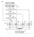
次に、図8を参照して、制御部32による送信電力制御について整理して説明する。図8は、送信電力制御のフローを示すものであり、アンテナの種別を判定する処理P1と、出力レベルを決定する処理P2と、送信部20に送信レベルを設定する処理P3とを備える。
Next, with reference to FIG. 8, the transmission power control by the
ステップ8aにおいて制御部32は、電圧GPIO_Rおよび電圧GPIO_Lを測定する。
ステップ8bにおいて制御部32は、図7に示した判定テーブルを参照し、電圧GPIO_Rと電圧GPIO_Lのレベルの組み合わせが、小型アンテナAに該当するか否かを判定する。ここで、小型アンテナAに該当する場合には、ステップ8eに移行し、一方、該当しない場合には、ステップ8cに移行する。
In
In step 8b, the
ステップ8cにおいて制御部32は、図7に示した判定テーブルを参照し、電圧GPIO_Rと電圧GPIO_Lのレベルの組み合わせが、小型アンテナBに該当するか否かを判定する。ここで、小型アンテナBに該当する場合には、ステップ8fに移行し、一方、該当しない場合には、ステップ8dに移行する。
In
ステップ8dにおいて制御部32は、図7に示した判定テーブルを参照し、電圧GPIO_Rと電圧GPIO_Lのレベルの組み合わせが、小型アンテナCに該当するか否かを判定する。ここで、小型アンテナCに該当する場合には、ステップ8gに移行し、一方、該当しない場合には、ステップ8hに移行する。
In
ステップ8eにおいて制御部32は、送信部20にレベルLv4を設定することを決定し、ステップ8iに移行する。
ステップ8fにおいて制御部32は、送信部20にレベルLv3を設定することを決定し、ステップ8iに移行する。
In
In step 8f, the
ステップ8gにおいて制御部32は、送信部20にレベルLv2を設定することを決定し、ステップ8iに移行する。
ステップ8hにおいて制御部32は、送信部20にレベルLv1を設定することを決定し、ステップ8iに移行する。
In
In
ステップ8iにおいて制御部32は、ステップ8e乃至8hのいずれかで決定した送信レベルを送信部20に設定し、当該処理を終了する。これにより、送信部20は、設定された送信レベルの無線周波信号を生成する。
In step 8i, the
以上のように、上記構成の送信装置では、ジャックJに接続されるプラグPがイヤホンのものであるか、いずれの小型アンテナであるかを判定し、送信部20が生成する無線周波信号のレベルを制御する。すなわち、ジャックJに接続されるアンテナの効率に応じて、送信電力を制御するようにしている。
As described above, in the transmission device configured as described above, it is determined whether the plug P connected to the jack J is an earphone or which small antenna, and the level of the radio frequency signal generated by the
したがって、上記構成の送信装置によれば、ユーザはFM波による送信を行いたい場合に、任意の形状のアンテナを接続すれば、そのアンテナに見合った送信電力で送信が行われるので、ユーザに特別な知識が無くても、法令を遵守し、簡単な操作で手軽に高品位な送信を行うことができる。 Therefore, according to the transmission apparatus configured as described above, when a user wants to perform transmission using FM waves, if an antenna of an arbitrary shape is connected, transmission is performed with transmission power corresponding to the antenna, so that the user is special. Even if you don't have a lot of knowledge, you can comply with laws and regulations and can easily perform high-quality transmission with simple operations.
また、上記実施の形態では、イヤホンジャックJにプラグPが接続された場合に限って、制御部31が送信部20を起動するとともに、抵抗器R1およびR2にVccを与えるようにしているので、無駄に無線周波信号が生成されたり、Vcc出力が無駄になることを防止できる。
In the above embodiment, only when the plug P is connected to the earphone jack J, the
なお、この発明は上記実施形態そのままに限定されるものではなく、実施段階ではその要旨を逸脱しない範囲で構成要素を変形して具体化できる。また上記実施形態に開示されている複数の構成要素を適宜組み合わせることによって種々の発明を形成できる。また例えば、実施形態に示される全構成要素からいくつかの構成要素を削除した構成も考えられる。さらに、異なる実施形態に記載した構成要素を適宜組み合わせてもよい。 Note that the present invention is not limited to the above-described embodiment as it is, and can be embodied by modifying the constituent elements without departing from the scope of the invention in the implementation stage. In addition, various inventions can be formed by appropriately combining a plurality of constituent elements disclosed in the embodiment. Further, for example, a configuration in which some components are deleted from all the components shown in the embodiment is also conceivable. Furthermore, you may combine suitably the component described in different embodiment.
その一例として例えば、上記第2の実施形態では、電圧GPIO_Rおよび電圧GPIO_Lに基づいて、アンテナの種別を判定するようにしたが、これに代わって例えば、アンテナ毎に設けた抵抗値を送信装置の制御部32が測定して、この測定結果からアンテナの種別を判定するようにしてもよい。
その他、この発明の要旨を逸脱しない範囲で種々の変形を施しても同様に実施可能であることはいうまでもない。
As an example, for example, in the second embodiment, the type of antenna is determined based on the voltage GPIO_R and the voltage GPIO_L. Instead, for example, the resistance value provided for each antenna is determined by the transmission device. The
In addition, it goes without saying that the present invention can be similarly implemented even if various modifications are made without departing from the gist of the present invention.
10…再生部、20…送信部、31…制御部、32…制御部、C1…コンデンサ、C2…コンデンサ、L1…インダクタンス、P…プラグ、SP1…右スピーカ、SP2…左スピーカ。
DESCRIPTION OF
Claims (7)
前記第2接点に無線周波信号を供給する送信手段と、
前記信号ラインと前記グランドの間に設けられたハイパスフィルタとを具備することを特徴とする送信装置。 A first contact connected to a signal line for outputting a reproduction signal, a second contact connected to the ground via an inductor, and an external device in which the signal line connected to the second contact functions as an antenna. A detachable means comprising a physically detachable mechanism;
Transmitting means for supplying a radio frequency signal to the second contact;
A transmission apparatus comprising: a high-pass filter provided between the signal line and the ground.
前記第2接点に無線周波信号を供給する送信手段と、
前記着脱手段に着けられた外部装置の種別を判定する判定手段と、
この判定手段の判定結果に応じて、前記送信手段が供給する無線周波信号の電力レベルを制御する制御手段とを具備することを特徴とする送信装置。 A first contact connected to a signal line for outputting a reproduction signal, a second contact connected to the ground via an inductor, and an external device in which the signal line connected to the second contact functions as an antenna. A detachable means comprising a physically detachable mechanism;
Transmitting means for supplying a radio frequency signal to the second contact;
Determining means for determining the type of external device attached to the attaching / detaching means;
A transmission apparatus comprising: a control unit that controls a power level of a radio frequency signal supplied by the transmission unit according to a determination result of the determination unit.
前記送信手段は、前記着脱手段に前記外部装置が着けられたことを前記検出手段が検出した場合に、前記第2接点に無線周波信号を供給することを特徴とする請求項1または請求項2に記載の送信装置。 And further comprising a detecting means for detecting that the external device is attached to the attaching / detaching means,
3. The transmission unit according to claim 1, wherein the transmission unit supplies a radio frequency signal to the second contact when the detection unit detects that the external device is attached to the attachment / detachment unit. The transmitting device described in 1.
前記送信手段は、前記入力手段が要求を受け付けた場合に、前記第2接点に無線周波信号を供給することを特徴とする請求項1または請求項2に記載の送信装置。 Furthermore, an input means for receiving a request from the user is provided,
3. The transmission device according to claim 1, wherein the transmission unit supplies a radio frequency signal to the second contact when the input unit receives a request. 4.
第1の抵抗器を介して前記信号ラインに所定の電圧を与えて、前記信号ラインをプルアップするプルアップ手段と、
前記着脱手段に着けられた外部装置内の抵抗値に応じて変化する前記信号ラインの電圧を測定して、前記外部装置の種別を判定する測定手段とを備えることを特徴とする請求項2に記載の送信装置。 The determination means includes
Pull-up means for applying a predetermined voltage to the signal line via a first resistor to pull up the signal line;
3. The measuring device according to claim 2, further comprising: a measuring unit that measures a voltage of the signal line that changes according to a resistance value in the external device attached to the attaching / detaching unit and determines a type of the external device. The transmitting device described.
前記プルアップ手段は、前記着脱手段に前記外部装置が着けられたことを前記検出手段が検出した場合に、第1の抵抗器を介して前記信号ラインに所定の電圧を与えて、前記信号ラインをプルアップすることを特徴とする請求項6に記載の送信装置。 And further comprising a detecting means for detecting that the external device is attached to the attaching / detaching means,
The pull-up means applies a predetermined voltage to the signal line via a first resistor when the detecting means detects that the external device is attached to the attaching / detaching means, and the signal line The transmission device according to claim 6, wherein the transmission device is pulled up.
Priority Applications (1)
| Application Number | Priority Date | Filing Date | Title |
|---|---|---|---|
| JP2008318912A JP2010141844A (en) | 2008-12-15 | 2008-12-15 | Transmission device |
Applications Claiming Priority (1)
| Application Number | Priority Date | Filing Date | Title |
|---|---|---|---|
| JP2008318912A JP2010141844A (en) | 2008-12-15 | 2008-12-15 | Transmission device |
Publications (1)
| Publication Number | Publication Date |
|---|---|
| JP2010141844A true JP2010141844A (en) | 2010-06-24 |
Family
ID=42351524
Family Applications (1)
| Application Number | Title | Priority Date | Filing Date |
|---|---|---|---|
| JP2008318912A Withdrawn JP2010141844A (en) | 2008-12-15 | 2008-12-15 | Transmission device |
Country Status (1)
| Country | Link |
|---|---|
| JP (1) | JP2010141844A (en) |
-
2008
- 2008-12-15 JP JP2008318912A patent/JP2010141844A/en not_active Withdrawn
Similar Documents
| Publication | Publication Date | Title |
|---|---|---|
| KR101473173B1 (en) | Earphone for mobile phone with Active Noise Cancellation function | |
| US9741334B2 (en) | Active noise cancellation in audio output device | |
| US20060003804A1 (en) | Radio signal relaying apparatus | |
| WO2015165345A1 (en) | Transmission method, mobile terminal, multi-channel earphone, and audio playing system | |
| CN105934792A (en) | In-line signal processor | |
| CN106792333A (en) | The sound system of television set | |
| KR101120019B1 (en) | Apparatus and method for receiving and reproducing broadcasting data through wireless communication | |
| JP2009194890A (en) | Mobile terminal, audio apparatus discrimination method, audio apparatus discrimination program, and program recording medium | |
| CN107424638A (en) | A kind of audio play control method of car-mounted terminal, apparatus and system | |
| JP5510072B2 (en) | Speaker device | |
| JP2008311825A (en) | Receiver and relay cable | |
| CN113206906B (en) | Electronic equipment components and digital headphones | |
| US20160140839A1 (en) | Data/commands through audio channel | |
| JPH09331209A (en) | Audio device and headphone having FM receiving circuit | |
| JP2010141844A (en) | Transmission device | |
| KR20130125112A (en) | Vehicle multimedia apparatus capable of managing audio output and method of managing audio output | |
| CN102656904A (en) | Apparatus comprising means for connecting to one or more external loudspeakers and means for detecting such connection | |
| CN207070268U (en) | Earphone | |
| CN102097115A (en) | Audio frequency playing method and mobile terminal | |
| CN101243516B (en) | Playback control device and audio system | |
| US20080225830A1 (en) | Circuit with generating phone-call ring via computer system and internet phone system using the circuit | |
| CN1855706B (en) | Music reproduction device for portable device | |
| JP4497544B2 (en) | Audio apparatus, recording apparatus, audio system, and audio signal output method | |
| JP2006157597A (en) | Sound equipment | |
| JP5505104B2 (en) | Speaker device |
Legal Events
| Date | Code | Title | Description |
|---|---|---|---|
| A300 | Withdrawal of application because of no request for examination |
Free format text: JAPANESE INTERMEDIATE CODE: A300 Effective date: 20120306 |