JP2010141833A - Phase control device for phased array antenna - Google Patents
Phase control device for phased array antenna Download PDFInfo
- Publication number
- JP2010141833A JP2010141833A JP2008318794A JP2008318794A JP2010141833A JP 2010141833 A JP2010141833 A JP 2010141833A JP 2008318794 A JP2008318794 A JP 2008318794A JP 2008318794 A JP2008318794 A JP 2008318794A JP 2010141833 A JP2010141833 A JP 2010141833A
- Authority
- JP
- Japan
- Prior art keywords
- phase
- signal
- phase shifter
- coaxial
- input
- Prior art date
- Legal status (The legal status is an assumption and is not a legal conclusion. Google has not performed a legal analysis and makes no representation as to the accuracy of the status listed.)
- Pending
Links
- 230000005540 biological transmission Effects 0.000 claims abstract description 9
- 230000010363 phase shift Effects 0.000 abstract description 10
- 230000008602 contraction Effects 0.000 description 7
- 239000000758 substrate Substances 0.000 description 6
- 238000010586 diagram Methods 0.000 description 5
- 230000032683 aging Effects 0.000 description 3
- 230000001681 protective effect Effects 0.000 description 2
- 238000004891 communication Methods 0.000 description 1
- 239000000470 constituent Substances 0.000 description 1
- 238000010295 mobile communication Methods 0.000 description 1
Images

Landscapes
- Waveguide Switches, Polarizers, And Phase Shifters (AREA)
Abstract
【課題】通過信号周波数に依存せず、かつ経年変化による影響が少ない高精度なフェーズドアレイアンテナの位相制御装置を提供する。
【解決手段】マイクロコンピュータ47は、PC48から与えられる目標指示値に従ってドライバ49を駆動し、アクチェータ24を動作させて同軸可変移相器21の移相量を設定する。送信信号は、同軸可変移相器21により位相制御されてアンテナへ送られる。同軸可変移相器21の入出力信号は、分岐器42、43を介して位相検出器44に入力される。位相検出器44は、同軸可変移相器21の入力信号と出力信号との間の位相差を検出し、その位相差をSin信号及びCos信号として出力し、A/D変換器45、46を介してマイクロコンピュータ47に入力する。マイクロコンピュータ47は、上記Sin信号及びCos信号がPC48から与えられている目標指示値に一致するようにアクチェータ24を制御する。
【選択図】 図2A highly accurate phased array antenna phase control apparatus that does not depend on a passing signal frequency and is less affected by secular change is provided.
A microcomputer 47 drives a driver 49 in accordance with a target instruction value given from a PC 48 and operates an actuator 24 to set a phase shift amount of a coaxial variable phase shifter 21. The transmission signal is phase-controlled by the coaxial variable phase shifter 21 and sent to the antenna. Input / output signals of the coaxial variable phase shifter 21 are input to the phase detector 44 via the branching units 42 and 43. The phase detector 44 detects a phase difference between the input signal and the output signal of the coaxial variable phase shifter 21, outputs the phase difference as a Sin signal and a Cos signal, and outputs A / D converters 45 and 46. To the microcomputer 47. The microcomputer 47 controls the actuator 24 so that the Sin signal and the Cos signal coincide with the target instruction value given from the PC 48.
[Selection] Figure 2
Description
本発明は、可変移相器例えば同軸可変移相器を用いてフェーズドアレイアンテナの給電位相を制御する位相制御装置に関する。 The present invention relates to a phase control device that controls a feeding phase of a phased array antenna using a variable phase shifter, for example, a coaxial variable phase shifter.
従来、例えば携帯電話基地局等においては、セクターアンテナとしてフェーズドアレイアンテナが使用されている。フェーズドアレイアンテナは、可変移相器を備え、給電位相を制御することによってアンテナの垂直面内指向性を真横よりも下向きに調整することが行われている(例えば、特許文献1参照。)。 Conventionally, for example, in a mobile phone base station, a phased array antenna is used as a sector antenna. A phased array antenna includes a variable phase shifter, and adjusts the directivity within the vertical plane of the antenna downward from right side by controlling the feeding phase (see, for example, Patent Document 1).
また、第三世代携帯電話であるIMT−2000(International Mobile Telecommunication 2000)による移動通信システムでは、安定した通信を確立するために、トラヒックに応じて1つのアンテナによるサービスエリアの大きさを頻繁に変更、すなわち、アンテナ垂直面における主ビームの方向(チルト角)を上下に変更する必要がある。このように1つのアンテナによるサービスエリアの大きさを変更する場合においても、可変移相器が使用される。 In addition, in a mobile communication system using IMT-2000 (International Mobile Telecommunication 2000), which is a third-generation mobile phone, the size of a service area using one antenna is frequently changed according to traffic in order to establish stable communication. That is, it is necessary to change the direction (tilt angle) of the main beam in the vertical plane of the antenna up and down. Thus, even when changing the size of the service area with one antenna, the variable phase shifter is used.
上記可変移相器としては、高精度の位相設定が可能な同軸可変移相器が使用されている。同軸可変移相器を伸縮する場合、一般的に同軸可変移相器をアクチェータ(1軸テーブル等)に取付け、パルスモータによりアクチェータを駆動して予め決められた伸縮長となるように制御している。この場合、同軸可変移相器を通過する信号の波長に合わせてアクチェータ伸縮長を予め決定し、制御目標値(位相)となるように制御している。
上記のように同軸可変移相器を使用した可変移相器において、アクチェータにより同軸可変移相器を駆動制御する場合、従来では同軸可変移相器を通過する信号の波長に合わせてアクチェータ伸縮長を予め設定して制御目標値となるようにしているので、通過信号の周波数が変わると制御目標値も変更しなければならなかった。また、アクチェータの経年変化により位置決めに誤差が生じるため、高精度位置決めを希望する場合には経年変化に強い高価なアクチェータを選定する必要があった。また、アクチェータをフィードバック制御する場合には、エンコーダ等の伸縮長測定センサが必要であった。 In the variable phase shifter using the coaxial variable phase shifter as described above, when the coaxial variable phase shifter is driven and controlled by the actuator, conventionally, the actuator extension / contraction length is matched to the wavelength of the signal passing through the coaxial variable phase shifter. Since the control target value is set in advance, the control target value must be changed when the frequency of the passing signal changes. In addition, since an error occurs in positioning due to aging of the actuator, it is necessary to select an expensive actuator that is resistant to aging when high precision positioning is desired. In addition, when the actuator is feedback-controlled, an expansion / contraction length measuring sensor such as an encoder is required.
本発明は上記の課題を解決するためになされたもので、通過信号周波数に依存せず、かつ経年変化による影響が少なく高精度で位相制御を行うことができるフェーズドアレイアンテナの位相制御装置を提供する。 The present invention has been made to solve the above-described problems, and provides a phase control apparatus for a phased array antenna that is capable of performing phase control with high accuracy and little influence of secular change without depending on a passing signal frequency. To do.
本発明に係るフェーズドアレイアンテナの位相制御装置は、フェーズドアレイアンテナに給電する送信信号の位相を可変設定する同軸可変移相器と、前記同軸可変移相器の入力信号と出力信号との間の位相差を検出する位相検出器と、前記同軸可変移相器の移相量を上位制御装置からの目標指示値に従って設定すると共に、前記位相検出器により検出された入出力信号間の位相差が前記上位制御装置からの目標指示値に一致するように調整する制御手段とを具備することを特徴とする。 A phase control apparatus for a phased array antenna according to the present invention includes a coaxial variable phase shifter that variably sets a phase of a transmission signal to be fed to the phased array antenna, and an input signal and an output signal between the coaxial variable phase shifter. The phase detector for detecting the phase difference and the phase shift amount of the coaxial variable phase shifter are set according to the target instruction value from the host controller, and the phase difference between the input and output signals detected by the phase detector is And a control means for adjusting so as to coincide with a target instruction value from the host controller.
本発明によれば、フェーズドアレイアンテナに対する給電位相を正確に制御でき、アンテナ特性を所望の特性とすることができる。また、同軸可変移相器の通過周波数が変わっても制御目標値を変更する必要はなく、常に安定した制御を行うことができる。更に、経年変化により影響が少なく、長期間に亘って高精度の移相制御が可能である。また、同軸可変移相器のフィードバック制御を行う場合、エンコーダ等の伸縮長測定用センサを必要とせず、使用する部品数を低減でき且つコストの低下を図ることができる。 According to the present invention, the feeding phase for the phased array antenna can be accurately controlled, and the antenna characteristics can be set to desired characteristics. Further, even if the pass frequency of the coaxial variable phase shifter changes, it is not necessary to change the control target value, and stable control can always be performed. Furthermore, there is little influence due to secular change, and highly accurate phase shift control is possible over a long period of time. Further, when feedback control of the coaxial variable phase shifter is performed, an expansion / contraction length measuring sensor such as an encoder is not required, and the number of parts to be used can be reduced and the cost can be reduced.
以下、図面を参照して本発明の一実施形態を説明する。 Hereinafter, an embodiment of the present invention will be described with reference to the drawings.
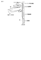
図1は、携帯電話基地局用セクターとして使用される送信用フェーズドアレイアンテナ装置の全体の概略構成図である。図1において、11はアンテナ支持基板で、このアンテナ支持基板11の前面側には、アンテナ基板12が装着される。上記アンテナ基板12には、図示しないが例えば45°直交偏波パッチアンテナ素子が複数個アレー配置されている。また、アンテナ支持基板11の背面側には、アンテナ素子の給電位相を制御する複数個の可変移相器13が設けられると共に、上記可変移相器13の移相量を制御する制御部14が設けられる。制御部14は、可変移相器13の移相量を制御してアンテナの垂直面における主ビーム20の方向(チルト角)を上下に変更する。また、上記アンテナは、必要に応じて保護ケース15内に収納される。
FIG. 1 is a schematic configuration diagram of an entire transmission phased array antenna device used as a mobile phone base station sector. In FIG. 1, reference numeral 11 denotes an antenna support substrate. An antenna substrate 12 is mounted on the front side of the antenna support substrate 11. For example, a plurality of 45 ° orthogonally polarized patch antenna elements are arrayed on the antenna substrate 12 (not shown). A plurality of variable phase shifters 13 for controlling the feeding phase of the antenna elements are provided on the back side of the antenna support substrate 11, and a control unit 14 for controlling the amount of phase shift of the variable phase shifter 13 is provided. Provided. The control unit 14 controls the amount of phase shift of the variable phase shifter 13 to change the direction (tilt angle) of the main beam 20 in the vertical plane of the antenna up and down. The antenna is housed in the
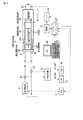
次に上記可変移相器13及び制御部14の構成例について図2を参照して説明する。なお、図2は説明を簡単にするため、制御部14により1つの可変移相器13を制御する場合について示している。 Next, configuration examples of the variable phase shifter 13 and the control unit 14 will be described with reference to FIG. Note that FIG. 2 shows a case where one variable phase shifter 13 is controlled by the control unit 14 in order to simplify the description.
また、図2では、可変移相器13として例えば略U字型に屈曲した同軸ラインをトロンボーンのように伸縮させて通過する信号の位相を可変する同軸可変移相器21を1軸のアクチェータ24に取付けて制御する場合の例を示している。このトロンボーン型の同軸可変移相器21は、所定のインピーダンス例えば50Ωのインピーダンスを保ったまま同軸管長を変化させて位相を調整する機能を備えている。上記同軸可変移相器21は、所定の間隔で平行に設けられた固定側同軸管22a、22b内に略U字状に形成された移動側同軸管23が可動可能に挿着されており、固定側同軸管22a、22bは固定側固定金具25に固定され、移動側同軸管23は移動側固定金具26に固定される。また、同軸可変移相器21の固定側同軸管22a、22bは、先端が固定側固定金具25から突出して設けられ、この突出部にそれぞれ入力用接栓27及び出力用接栓28が設けられる。
In FIG. 2, the variable phase shifter 13 includes a coaxial
上記移動側固定金具26は、水平方向の中心にネジ穴が設けられ、このネジ穴に駆動軸31が螺着される。この駆動軸31は、図示しないが両端部が軸受けにより回転可能に保持されている。上記アクチェータ24は、パルスモータ32を備え、このパルスモータ32により駆動軸31を回転駆動して移動側固定金具26を同軸可変移相器21の移動側同軸管23を左右方向に移動させ、信号の位相を調整する。
The moving
そして、上記同軸可変移相器21の入力用接栓27には、送信機の電力増幅器41から出力される送信信号が入力され、同軸可変移相器21の出力用接栓28から出力される送信信号は図1に示したアンテナへ送られ、このアンテナから外部に送信される。また、上記電力増幅器41と入力用接栓27との間に分岐器42が設けられ、電力増幅器41から同軸可変移相器21に入力される送信信号が分岐されて位相検出器44に入力される。また、同軸可変移相器21の出力用接栓28とアンテナとの間に分岐器43が設けられ、同軸可変移相器21から出力される送信信号が分岐されて位相検出器44に入力される。
A transmission signal output from the
位相検出器44は、分岐器42、43により分岐された信号、即ち同軸可変移相器21の入力信号と出力信号の位相差を検出するもので、検出した位相差をSin信号、Cos信号として出力する。上記位相検出器44については詳細を後述する。上記位相検出器44から出力されるSin信号及びCos信号は、それぞれA/D変換器45、46によりデジタル信号に変換され、マイクロコンピュータ47へ送られる。また、このマイクロコンピュータ47には、全体を制御する上位の制御装置、例えばパーソナルコンピュータ(以下、PCと略称する)48から目標値指示値が位相値で与えられる。マイクロコンピュータ47は、PC48から与えられる目標指示値(位相値)に従って動作し、ドライバ49を介してパルスモータ32を駆動し、アクチェータ24を動作させる。上記マイクロコンピュータ47及びドライバ49には電源部50から動作電源が供給される。
The
また、マイクロコンピュータ47は、位相検出器44からA/D変換器45、46を介して送られてくるSin信号、Cos信号がPC48から与えられている目標指示値となるようにドライバ49によりパルスモータ32を回転駆動する。また、マイクロコンピュータ47は、位相検出器44で検出されたSin信号とCos信号から得られるベクトル量から電力量を求め、この電力量に基づいて電力増幅器41の温度特性、同軸可変移相器減衰量を補正するゲイン制御信号をD/A変換器51を介して電力増幅器41へ出力する。
Further, the
図3は、上記位相検出器44の詳細な回路構成図である。図3において、61a、61bは位相検出器44の入力端子で、該入力端子61a、61bには図2に示した分岐器42、43で分岐された信号がそれぞれ入力される。上記入力端子61aに入力された信号は分配器62により2分配されてミキサ64、65の一方の入力端子に入力される。また、入力端子61bに入力された信号は分配器63により2分配され、一方の分配信号はミキサ64の他方の入力端子に入力され、他方の分配信号は−90°の移相器66を介してミキサ65の他方の入力端子に入力される。そして、ミキサ64の出力信号はローパスフィルタ(LPF)67を介してSin信号として取出され、ミキサ65の出力信号はローパスフィルタ(LPF)68を介してCos信号として取出される。上記ローパスフィルタ67から出力されるSin信号、及びローパスフィルタ68から出力されるCos信号は、図2に示したようにA/D変換器45、46を介してマイクロコンピュータ47へ送られる。
FIG. 3 is a detailed circuit configuration diagram of the
次に上記のように構成されたフェーズドアレイアンテナの位相制御装置の動作を図1ないし図3を参照して説明する。PC48は、マイクロコンピュータ47に対して同軸可変移相器21の目標指示値(位相値)を与える。マイクロコンピュータ47は、PC48から与えられる目標指示値に従ってドライバ49を駆動し、アクチェータ24を動作させて同軸可変移相器21の移相量を設定する。
Next, the operation of the phase control apparatus for the phased array antenna configured as described above will be described with reference to FIGS. The
同時に電力増幅器41から出力される送信信号は、同軸可変移相器21の入力用接栓27に入力され、同軸可変移相器21で位相が制御されて出力用接栓28からアンテナへ送られる。このとき同軸可変移相器21の入力信号及び出力信号は、分岐器42、43により位相検出器44に分配される。位相検出器44は、分岐器42、43から入力される同軸可変移相器21の入力信号と出力信号との間の位相差を検出し、その位相差をSin信号及びCos信号として出力する。
At the same time, the transmission signal output from the
上記位相検出器44により検出された同軸可変移相器21の入力信号と出力信号との間の位相差は、A/D変換器45、46によりデジタル信号に変換されてマイクロコンピュータ47に入力される。マイクロコンピュータ47は、位相検出器44で検出されたSin信号、Cos信号がPC48から与えられている目標指示値に一致するようにドライバ49によりパルスモータ32を回転駆動し、同軸可変移相器21の移動側固定金具26を移動させて移動側同軸管23の位置を調整する。
The phase difference between the input signal and the output signal of the coaxial
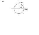
また、マイクロコンピュータ47は、位相検出器44で検出されたSin信号、Cos信号から得られるベクトル量の大きさ(絶対値)から電力量を求め、この電力量から電力増幅器41の温度特性、同軸可変移相器の減衰量を補正するゲイン制御信号を生成し、このゲイン制御信号によりD/A変換器51を介して電力増幅器41を制御する。この場合、位相検出器44により検出されたSin信号及びCos信号を直交軸で表現すると、図4に示すようになり、ベクトル量の大きさ(絶対値)rの角度θから同軸可変移相器21の入出力間の位相差、ベクトル量の大きさrから電力量を知ることができる。
Further, the
上記のようにPC48から出力される目標値指示に従ってマイクロコンピュータ47によりアクチェータ24を駆動して同軸可変移相器21の伸縮量即ち移相量を制御し、かつ、同軸可変移相器21の入出力間の位相差を位相検出器44で検出してマイクロコンピュータ47にフィードバックし、アクチェータ24を介して同軸可変移相器21の移相量を微調整することにより、同軸可変移相器21の高精度の移相量の設定が可能となる。このためフェーズドアレイアンテナに対する給電位相を正確に制御でき、アンテナ特性を所望の特性とすることができる。
As described above, the
更に、アクチェータ24の経年変化等により機構的に多少の位置決め誤差を生じるような場合であっても、同軸可変移相器21の入出力間の位相差を検出し、その検出位相差が目標位相差に一致するようにアクチェータ24を制御することにより、高精度に位相の設定が可能である。このため経年変化に強い高価なアクチェータを使用する必要はなく、比較的安価なアクチェータであっても長期間に亘って高精度で且つ安定した移相量の設定行うことができる。
Further, even if a slight positioning error is caused mechanically due to aging of the actuator 24 or the like, the phase difference between the input and output of the coaxial
また、アクチェータ24のフィードバック制御を行う場合、エンコーダ等の伸縮長測定用センサを必要とせず、使用する部品数を低減し得ると共にコストの低下を図ることができる。 Further, when feedback control of the actuator 24 is performed, an expansion / contraction length measuring sensor such as an encoder is not required, so that the number of parts to be used can be reduced and cost can be reduced.
なお、上記実施形態では、アンテナ基板12に45°直交偏波パッチアンテナ素子を複数個アレー配置してなるフェーズドアレイアンテナを用いた場合について説明したが、その他、例えばクロスダイポールアンテナ素子や多素子八木式アンテナ、更には多段コーリニヤアンテナ等を用いた構成したフェーズドアレイアンテナにおいても、上記実施形態と同様にして実施し得るものである。 In the above embodiment, the case where the phased array antenna formed by arranging a plurality of 45 ° orthogonally polarized patch antenna elements on the antenna substrate 12 is described. However, for example, a cross dipole antenna element or a multi-element Yagi is used. A phased array antenna configured using a multi-stage antenna or a multi-stage collier antenna can be implemented in the same manner as in the above embodiment.
また、本発明は、上記実施形態そのままに限定されるものではなく、実施段階ではその要旨を逸脱しない範囲で構成要素を変形して具体化できるものである。 Further, the present invention is not limited to the above-described embodiment as it is, and can be embodied by modifying constituent elements without departing from the scope of the invention in the implementation stage.
11…アンテナ支持基板、12…アンテナ基板、13…可変移相器、14…制御部、15…保護ケース、20…主ビーム、21…同軸可変移相器、22a、22b…固定側同軸管、23…移動側同軸管、24…アクチェータ、25…固定側固定金具、26…移動側固定金具、27…入力用接栓、28…出力用接栓、31…アクチェータの駆動軸、32…パルスモータ、41…電力増幅器、42、43…分岐器、44…位相検出器、45、46…A/D変換器、47…マイクロコンピュータ、48…パーソナルコンピュータ(PC)、49…パルスモータのドライバ、50…電源部、51…D/A変換器、61a、61b…位相検出器の入力端子、62、63…分配器、64、65…ミキサ、66…−90°の移相器、67、68…ローパスフィルタ(LPF)。
DESCRIPTION OF SYMBOLS 11 ... Antenna support board, 12 ... Antenna board, 13 ... Variable phase shifter, 14 ... Control part, 15 ... Protective case, 20 ... Main beam, 21 ... Coaxial variable phase shifter, 22a, 22b ... Fixed side coaxial tube, DESCRIPTION OF SYMBOLS 23 ... Moving side coaxial pipe, 24 ... Actuator, 25 ... Fixed side fixing bracket, 26 ... Moving side fixing bracket, 27 ... Input plug, 28 ... Output plug, 31 ... Actuator drive shaft, 32 ... Pulse motor , 41 ... Power amplifier, 42, 43 ... Branch, 44 ... Phase detector, 45, 46 ... A / D converter, 47 ... Microcomputer, 48 ... Personal computer (PC), 49 ... Pulse motor driver, 50 ...
Claims (1)
Priority Applications (1)
| Application Number | Priority Date | Filing Date | Title |
|---|---|---|---|
| JP2008318794A JP2010141833A (en) | 2008-12-15 | 2008-12-15 | Phase control device for phased array antenna |
Applications Claiming Priority (1)
| Application Number | Priority Date | Filing Date | Title |
|---|---|---|---|
| JP2008318794A JP2010141833A (en) | 2008-12-15 | 2008-12-15 | Phase control device for phased array antenna |
Publications (1)
| Publication Number | Publication Date |
|---|---|
| JP2010141833A true JP2010141833A (en) | 2010-06-24 |
Family
ID=42351516
Family Applications (1)
| Application Number | Title | Priority Date | Filing Date |
|---|---|---|---|
| JP2008318794A Pending JP2010141833A (en) | 2008-12-15 | 2008-12-15 | Phase control device for phased array antenna |
Country Status (1)
| Country | Link |
|---|---|
| JP (1) | JP2010141833A (en) |
Cited By (2)
| Publication number | Priority date | Publication date | Assignee | Title |
|---|---|---|---|---|
| CN106443211A (en) * | 2016-07-29 | 2017-02-22 | 西安空间无线电技术研究所 | An integrated correction system and correction method suitable for different active array antennas |
| CN114447545A (en) * | 2022-01-04 | 2022-05-06 | 中信科移动通信技术股份有限公司 | Phase shifter, electric tuning controller, antenna and antenna beam angle adjusting method |
Citations (2)
| Publication number | Priority date | Publication date | Assignee | Title |
|---|---|---|---|---|
| JPS548443A (en) * | 1977-06-22 | 1979-01-22 | Toshiba Corp | Directivity control device |
| JPH088660A (en) * | 1994-06-24 | 1996-01-12 | Nec Corp | Phase control circuit for power synthesis |
-
2008
- 2008-12-15 JP JP2008318794A patent/JP2010141833A/en active Pending
Patent Citations (2)
| Publication number | Priority date | Publication date | Assignee | Title |
|---|---|---|---|---|
| JPS548443A (en) * | 1977-06-22 | 1979-01-22 | Toshiba Corp | Directivity control device |
| JPH088660A (en) * | 1994-06-24 | 1996-01-12 | Nec Corp | Phase control circuit for power synthesis |
Cited By (4)
| Publication number | Priority date | Publication date | Assignee | Title |
|---|---|---|---|---|
| CN106443211A (en) * | 2016-07-29 | 2017-02-22 | 西安空间无线电技术研究所 | An integrated correction system and correction method suitable for different active array antennas |
| CN106443211B (en) * | 2016-07-29 | 2019-03-26 | 西安空间无线电技术研究所 | Integrated correction system and method suitable for different active array antennas |
| CN114447545A (en) * | 2022-01-04 | 2022-05-06 | 中信科移动通信技术股份有限公司 | Phase shifter, electric tuning controller, antenna and antenna beam angle adjusting method |
| CN114447545B (en) * | 2022-01-04 | 2023-07-11 | 中信科移动通信技术股份有限公司 | Phase shifter, electric control device, antenna and antenna beam angle adjusting method |
Similar Documents
| Publication | Publication Date | Title |
|---|---|---|
| US7990329B2 (en) | Dual staggered vertically polarized variable azimuth beamwidth antenna for wireless network | |
| US8085211B2 (en) | Single drive variable azimuth and beam tilt antenna for wireless network | |
| US7098859B2 (en) | Antenna unit | |
| US7224246B2 (en) | Apparatus for steering an antenna system | |
| EP2823532B1 (en) | Aperiodic phased array antenna with single bit phase shifters | |
| US6975268B2 (en) | Phased array antenna including a distributed phase calibrator and associated method | |
| US8330668B2 (en) | Dual stagger off settable azimuth beam width controlled antenna for wireless network | |
| US10921414B2 (en) | Tracking receiver with integrated phase calibration and method | |
| CN104904064B (en) | Method and apparatus for beamforming | |
| US7710344B2 (en) | Single pole vertically polarized variable azimuth beamwidth antenna for wireless network | |
| JP2012205213A (en) | Tracking antenna device adjustment method and tracking antenna device | |
| JP2010141833A (en) | Phase control device for phased array antenna | |
| CN203039673U (en) | An infrared microwave object simulating device | |
| CN107462779B (en) | Testing method of device for measuring phase error of cable between microwave imaging satellite boards | |
| JP3725851B2 (en) | Radar / target wave simulator | |
| JP3769513B2 (en) | Array antenna device | |
| KR102180722B1 (en) | Slot array antenna and design method thereof | |
| JP2012109752A (en) | Array antenna apparatus and impedance matching method thereof | |
| JP2013005059A (en) | Radio communication device, transmission method and program | |
| CN111404621A (en) | Device and method for rapid calibration of linear array | |
| US20060077099A1 (en) | Method and apparatus for pointing the beam of a wind profiler | |
| GB2426635A (en) | Phase shifting arrangement | |
| JP4745686B2 (en) | Directional error compensation method and apparatus for array-fed reflector multi-beam antenna | |
| EP1800366A1 (en) | Antenna system compensating a change in radiation characteristics | |
| JP7457073B2 (en) | BEAM FORMING APPARATUS AND BEAM CONTROL METHOD |
Legal Events
| Date | Code | Title | Description |
|---|---|---|---|
| A621 | Written request for application examination |
Free format text: JAPANESE INTERMEDIATE CODE: A621 Effective date: 20111111 |
|
| A977 | Report on retrieval |
Free format text: JAPANESE INTERMEDIATE CODE: A971007 Effective date: 20121022 |
|
| A131 | Notification of reasons for refusal |
Free format text: JAPANESE INTERMEDIATE CODE: A131 Effective date: 20121030 |
|
| A02 | Decision of refusal |
Free format text: JAPANESE INTERMEDIATE CODE: A02 Effective date: 20130312 |