JP2010141793A - Display terminal unit - Google Patents

Display terminal unit Download PDF

Info

Publication number
JP2010141793A
JP2010141793A JP2008318323A JP2008318323A JP2010141793A JP 2010141793 A JP2010141793 A JP 2010141793A JP 2008318323 A JP2008318323 A JP 2008318323A JP 2008318323 A JP2008318323 A JP 2008318323A JP 2010141793 A JP2010141793 A JP 2010141793A
Authority
JP
Japan
Prior art keywords
terminal device
display terminal
display screen
identification mark
display
Prior art date
Legal status (The legal status is an assumption and is not a legal conclusion. Google has not performed a legal analysis and makes no representation as to the accuracy of the status listed.)
Pending
Application number
JP2008318323A
Other languages
Japanese (ja)
Inventor
Mizuho Nakamura
瑞穂 中村
Current Assignee (The listed assignees may be inaccurate. Google has not performed a legal analysis and makes no representation or warranty as to the accuracy of the list.)
Brother Industries Ltd
Original Assignee
Brother Industries Ltd
Priority date (The priority date is an assumption and is not a legal conclusion. Google has not performed a legal analysis and makes no representation as to the accuracy of the date listed.)
Filing date
Publication date
Application filed by Brother Industries Ltd filed Critical Brother Industries Ltd
Priority to JP2008318323A priority Critical patent/JP2010141793A/en
Priority to US12/635,690 priority patent/US20100149219A1/en
Priority to CN200910258791A priority patent/CN101751903A/en
Priority to EP09015436A priority patent/EP2199865A2/en
Publication of JP2010141793A publication Critical patent/JP2010141793A/en
Pending legal-status Critical Current

Links

Images

Classifications

    • HELECTRICITY
    • H04ELECTRIC COMMUNICATION TECHNIQUE
    • H04NPICTORIAL COMMUNICATION, e.g. TELEVISION
    • H04N1/00Scanning, transmission or reproduction of documents or the like, e.g. facsimile transmission; Details thereof
    • H04N1/00127Connection or combination of a still picture apparatus with another apparatus, e.g. for storage, processing or transmission of still picture signals or of information associated with a still picture
    • H04N1/00129Connection or combination of a still picture apparatus with another apparatus, e.g. for storage, processing or transmission of still picture signals or of information associated with a still picture with a display device, e.g. CRT or LCD monitor
    • GPHYSICS
    • G03PHOTOGRAPHY; CINEMATOGRAPHY; ANALOGOUS TECHNIQUES USING WAVES OTHER THAN OPTICAL WAVES; ELECTROGRAPHY; HOLOGRAPHY
    • G03GELECTROGRAPHY; ELECTROPHOTOGRAPHY; MAGNETOGRAPHY
    • G03G15/00Apparatus for electrographic processes using a charge pattern
    • G03G15/60Apparatus which relate to the handling of originals
    • G03G15/607Apparatus which relate to the handling of originals for detecting size, presence or position of original
    • GPHYSICS
    • G06COMPUTING; CALCULATING OR COUNTING
    • G06FELECTRIC DIGITAL DATA PROCESSING
    • G06F1/00Details not covered by groups G06F3/00 - G06F13/00 and G06F21/00
    • G06F1/16Constructional details or arrangements
    • G06F1/1613Constructional details or arrangements for portable computers
    • G06F1/1633Constructional details or arrangements of portable computers not specific to the type of enclosures covered by groups G06F1/1615 - G06F1/1626
    • G06F1/1656Details related to functional adaptations of the enclosure, e.g. to provide protection against EMI, shock, water, or to host detachable peripherals like a mouse or removable expansions units like PCMCIA cards, or to provide access to internal components for maintenance or to removable storage supports like CDs or DVDs, or to mechanically mount accessories
    • G06F1/166Details related to functional adaptations of the enclosure, e.g. to provide protection against EMI, shock, water, or to host detachable peripherals like a mouse or removable expansions units like PCMCIA cards, or to provide access to internal components for maintenance or to removable storage supports like CDs or DVDs, or to mechanically mount accessories related to integrated arrangements for adjusting the position of the main body with respect to the supporting surface, e.g. legs for adjusting the tilt angle
    • GPHYSICS
    • G03PHOTOGRAPHY; CINEMATOGRAPHY; ANALOGOUS TECHNIQUES USING WAVES OTHER THAN OPTICAL WAVES; ELECTROGRAPHY; HOLOGRAPHY
    • G03GELECTROGRAPHY; ELECTROPHOTOGRAPHY; MAGNETOGRAPHY
    • G03G2215/00Apparatus for electrophotographic processes
    • G03G2215/00172Apparatus for electrophotographic processes relative to the original handling
    • G03G2215/00177Apparatus for electrophotographic processes relative to the original handling for scanning
    • G03G2215/00181Apparatus for electrophotographic processes relative to the original handling for scanning concerning the original's state of motion
    • G03G2215/00185Apparatus for electrophotographic processes relative to the original handling for scanning concerning the original's state of motion original at rest
    • GPHYSICS
    • G03PHOTOGRAPHY; CINEMATOGRAPHY; ANALOGOUS TECHNIQUES USING WAVES OTHER THAN OPTICAL WAVES; ELECTROGRAPHY; HOLOGRAPHY
    • G03GELECTROGRAPHY; ELECTROPHOTOGRAPHY; MAGNETOGRAPHY
    • G03G2215/00Apparatus for electrophotographic processes
    • G03G2215/00172Apparatus for electrophotographic processes relative to the original handling
    • G03G2215/00206Original medium
    • G03G2215/00312Other special types
    • HELECTRICITY
    • H04ELECTRIC COMMUNICATION TECHNIQUE
    • H04NPICTORIAL COMMUNICATION, e.g. TELEVISION
    • H04N1/00Scanning, transmission or reproduction of documents or the like, e.g. facsimile transmission; Details thereof
    • H04N1/00127Connection or combination of a still picture apparatus with another apparatus, e.g. for storage, processing or transmission of still picture signals or of information associated with a still picture
    • HELECTRICITY
    • H04ELECTRIC COMMUNICATION TECHNIQUE
    • H04NPICTORIAL COMMUNICATION, e.g. TELEVISION
    • H04N1/00Scanning, transmission or reproduction of documents or the like, e.g. facsimile transmission; Details thereof
    • H04N1/04Scanning arrangements, i.e. arrangements for the displacement of active reading or reproducing elements relative to the original or reproducing medium, or vice versa
    • H04N1/10Scanning arrangements, i.e. arrangements for the displacement of active reading or reproducing elements relative to the original or reproducing medium, or vice versa using flat picture-bearing surfaces
    • HELECTRICITY
    • H04ELECTRIC COMMUNICATION TECHNIQUE
    • H04NPICTORIAL COMMUNICATION, e.g. TELEVISION
    • H04N2201/00Indexing scheme relating to scanning, transmission or reproduction of documents or the like, and to details thereof
    • H04N2201/0077Types of the still picture apparatus
    • H04N2201/0081Image reader
    • HELECTRICITY
    • H04ELECTRIC COMMUNICATION TECHNIQUE
    • H04NPICTORIAL COMMUNICATION, e.g. TELEVISION
    • H04N2201/00Indexing scheme relating to scanning, transmission or reproduction of documents or the like, and to details thereof
    • H04N2201/04Scanning arrangements
    • H04N2201/0402Arrangements not specific to a particular one of the scanning methods covered by groups H04N1/04 - H04N1/207
    • H04N2201/0438Scanning displays; Scanning large surfaces, e.g. projection screens, writing boards

Abstract

<P>PROBLEM TO BE SOLVED: To provide a display terminal unit capable of easily adjusting a read region of a copying machine and the display screen of the display terminal unit to appropriate positions when copying the display screen of the display terminal unit. <P>SOLUTION: The display terminal unit 1 is placed on a platen 101 of the copying machine 100 so that the read region of the copying machine 100 faces the display screen of the display terminal unit 1. The display terminal unit 1 is aligned so that a linear back identification mark 11 indicating the position of the short side of the display screen is linearly connected to a short-side reference line 107, namely the short side of the platen 101 when viewed from an upper portion of the platen 101. Also, the display terminal unit 1 is aligned so that a linear back identification mark 12 indicating the position of the long side of the display screen is linearly connected to a long-side reference line 108, namely the long side of the platen 101. <P>COPYRIGHT: (C)2010,JPO&INPIT

Description

本発明は、筐体に表示画面が設けられた表示端末装置に関する。   The present invention relates to a display terminal device in which a display screen is provided on a housing.

近年、スケジュールおよび書籍等の情報を不揮発性メモリに記憶して、表示画面に表示する電子機器である表示端末装置が普及している。この表示端末装置は、コンパクト、かつ軽量であるため、持ち運びが容易である。このような表示端末装置の表示画面に表示される情報を印刷したい場合、ユーザは、ケーブルを用いてプリンタに表示端末装置を直接接続して印刷する。しかし、プリンタに接続して印刷設定を行う手間をかけず、簡易に表示端末装置の表示画面に表示された情報を出力したい場合がある。その様な場合に、コピー機の原稿の読取個所である原稿台上に、原稿台と表示画面とが対向するように表示端末装置を載置し、表示画面に表示される情報を複写することが提案されている(例えば、特許文献1参照)。
特開2006−254224号公報
In recent years, display terminal devices, which are electronic devices that store information such as schedules and books in a nonvolatile memory and display the information on a display screen, have become widespread. Since this display terminal device is compact and lightweight, it is easy to carry. When printing information displayed on the display screen of such a display terminal device, the user directly connects the display terminal device to the printer using a cable and prints it. However, there is a case where it is desired to simply output information displayed on the display screen of the display terminal device without the trouble of connecting to a printer and performing print settings. In such a case, a display terminal device is placed on the document table, which is a reading position of the document of the copier, so that the document table and the display screen face each other, and the information displayed on the display screen is copied. Has been proposed (see, for example, Patent Document 1).
JP 2006-254224 A

しかしながら、上記特許文献1に記載の表示端末装置では、原稿台上での表示画面の位置をコピー機の読取領域に合わせようとしても、表示端末装置の表示画面をユーザは直接視認できない。従って、コピー機の読取領域と、表示端末装置の表示画面とを最適な位置に合わせることが困難であるという問題点があった。その結果、表示画面が全部複写できない場合があるという問題点もあった。   However, in the display terminal device described in Patent Document 1, even if an attempt is made to align the position of the display screen on the document table with the reading area of the copier, the user cannot directly view the display screen of the display terminal device. Therefore, there is a problem that it is difficult to align the reading area of the copier and the display screen of the display terminal device at an optimum position. As a result, there is a problem that the entire display screen cannot be copied.

本発明は、上記問題点を解決するためになされたものであり、表示端末装置の表示画面を複写する場合に、コピー機の読取領域と、表示端末装置の表示画面とを最適な位置に容易に合わせることができる表示端末装置を提供することを目的とする。   The present invention has been made to solve the above problems, and when copying the display screen of the display terminal device, the reading area of the copier and the display screen of the display terminal device can be easily placed at optimum positions. An object of the present invention is to provide a display terminal device that can be adapted to the above.

上記目的を達成するために、請求項1に係る発明の表示端末装置は、正面および背面を少なくとも有する筐体の前記正面に情報を表示する表示画面が設けられた表示端末装置であって、前記正面以外の面に、前記正面における前記表示画面の位置を識別するための識別マークが設けられていることを特徴とする。   To achieve the above object, a display terminal device according to claim 1 is a display terminal device provided with a display screen for displaying information on the front surface of a housing having at least a front surface and a back surface, An identification mark for identifying the position of the display screen on the front surface is provided on a surface other than the front surface.

また、請求項2に係る発明の表示端末装置は、請求項1に記載の発明の構成に加えて、前記識別マークは、前記背面に設けられていることを特徴とする。   According to a second aspect of the present invention, in addition to the configuration of the first aspect of the invention, the identification mark is provided on the back surface.

また、請求項3に係る発明の表示端末装置は、請求項1又は2に記載の発明の構成に加えて、前記筐体は側面を有し、前記識別マークは、前記側面に設けられていることを特徴とする。   According to a third aspect of the present invention, in addition to the configuration of the first or second aspect of the invention, the housing has a side surface, and the identification mark is provided on the side surface. It is characterized by that.

また、請求項4に係る発明の表示端末装置は、請求項1乃至3のいずれかに記載の発明の構成に加えて、前記表示画面は平面視略四角形であり、前記識別マークは、前記表示画面の輪郭線の隣り合う二辺の位置を示すことを特徴とする。   According to a fourth aspect of the present invention, in addition to the configuration of the first aspect of the present invention, the display screen is substantially rectangular in plan view, and the identification mark is the display The position of two adjacent sides of the contour line of the screen is indicated.

また、請求項5に係る発明の表示端末装置は、請求項1乃至3のいずれかに記載の発明の構成に加えて、前記表示画面は平面視略四角形であり、前記識別マークは、前記表示画面の輪郭線の少なくとも一つの角の位置を示すことを特徴とする。   According to a fifth aspect of the present invention, in addition to the configuration of the first aspect of the present invention, the display screen is substantially rectangular in plan view, and the identification mark is the display The position of at least one corner of the outline of the screen is indicated.

また、請求項6に係る発明の表示端末装置は、請求項5に記載の発明の構成に加えて、前記識別マークは、前記少なくとも一つの角の位置として前記表示画面の輪郭線の左上の角の位置を示すことを特徴とする。   According to a sixth aspect of the present invention, in addition to the configuration of the fifth aspect of the present invention, the identification mark has the upper left corner of the outline of the display screen as the position of the at least one corner. It is characterized by showing the position of.

また、請求項7に係る発明の表示端末装置は、請求項6に記載の発明の構成に加えて、前記識別マークは、前記少なくとも一つの角の位置として前記表示画面の輪郭線の右下の角の位置を示すことを特徴とする。   According to a seventh aspect of the present invention, in addition to the configuration of the sixth aspect of the invention, the identification mark is positioned at a lower right of the outline of the display screen as the position of the at least one corner. The position of the corner is indicated.

また、請求項8に係る発明の表示端末装置は、請求項5に記載の発明の構成に加えて、前記識別マークは、前記少なくとも一つの角の位置として前記表示画面の輪郭線の四つの角の位置を示すことを特徴とする。   According to an eighth aspect of the present invention, in addition to the configuration of the fifth aspect of the present invention, the identification mark has four corners of the outline of the display screen as the position of the at least one corner. It is characterized by showing the position of.

また、請求項9に係る発明の表示端末装置は、請求項5に記載の発明の構成に加えて、前記識別マークは、前記少なくとも一つの角の位置として前記表示画面の輪郭線の上部の角および下部の角を示し、前記上部の角および前記下部の角でそれぞれ異なるマークであることを特徴とする。   According to a ninth aspect of the present invention, in addition to the configuration of the fifth aspect of the present invention, the identification mark is an upper corner of the display screen outline as the position of the at least one corner. And a lower corner, and the upper corner and the lower corner are different marks.

また、請求項10に係る発明の表示端末装置は、請求項1又は2に記載の発明の構成に加えて、前記識別マークは、前記表示画面を前記背面に投影した領域の輪郭線であることを特徴とする。   Further, in the display terminal device of the invention according to claim 10, in addition to the configuration of the invention of claim 1 or 2, the identification mark is an outline of a region in which the display screen is projected on the back surface. It is characterized by.

また、請求項11に係る発明の表示端末装置は、請求項1乃至10のいずれかに記載の構成に加えて、前記識別マークは、前記表示画面の中心の位置を示すことを特徴とする。   According to an eleventh aspect of the present invention, in addition to the configuration according to any one of the first to tenth aspects, the identification mark indicates the center position of the display screen.

また、請求項12に係る発明の表示端末装置は、請求項1乃至11のいずれかに記載の構成に加えて、前記識別マークは、線で構成されていることを特徴とする。   A display terminal device according to a twelfth aspect of the present invention is characterized in that, in addition to the configuration according to any one of the first to eleventh aspects, the identification mark is configured by a line.

また、請求項13に係る発明の表示端末装置は、請求項1乃至12のいずれかに記載の構成に加えて、前記識別マークは、前記識別マークが設けられた前記背面および側面の少なくとも一方の端部まで到達することを特徴とする。   The display terminal device according to a thirteenth aspect of the present invention is the display terminal device according to any one of the first to twelfth aspects, wherein the identification mark is at least one of the back surface and the side surface provided with the identification mark. It is characterized by reaching the end.

また、請求項14に係る発明の表示端末装置は、請求項1乃至13のいずれかに記載の構成に加えて、前記識別マークは、前記筐体の外面に対して凹部として形成されていることを特徴とする。   Further, in the display terminal device of the invention according to claim 14, in addition to the configuration of any of claims 1 to 13, the identification mark is formed as a recess with respect to the outer surface of the housing. It is characterized by.

請求項1に係る発明の表示端末装置には、正面および背面を少なくとも有する筐体の正面に情報を表示する表示画面が設けられ、正面以外の面に、表示画面の位置を識別するための識別マークが設けられている。よって、ユーザは、表示端末装置の表示画面を視認困難な場合でも、識別マークを目安として、表示端末装置をコピー機の原稿台に載置することにより、コピー機の読取領域に対して最適な位置に表示画面の位置合わせを行うことができる。   The display terminal device of the invention according to claim 1 is provided with a display screen for displaying information on the front surface of the housing having at least a front surface and a back surface, and identification for identifying the position of the display screen on a surface other than the front surface A mark is provided. Therefore, even when it is difficult to visually recognize the display screen of the display terminal device, the user can use the identification mark as a guide to place the display terminal device on the manuscript table of the copy machine, so that the optimum reading area for the copy machine can be obtained. The display screen can be aligned with the position.

また、請求項2に係る発明の表示端末装置では、識別マークは、背面に設けられている。表示端末装置の表示画面とコピー機の原稿台とが対向する様に表示端末装置を載置した状態であっても、背面は視認できる。よって、請求項1に記載の発明の効果に加え、ユーザは、表示端末装置の表示画面を視認困難な場合でも、視認可能な背面に設けられた識別マークを目安として、表示端末装置をコピー機の原稿台に載置することにより、コピー機の読取領域に対して表示画面の位置合わせを行うことができる。   In the display terminal device of the invention according to claim 2, the identification mark is provided on the back surface. Even when the display terminal device is placed so that the display screen of the display terminal device and the document table of the copying machine face each other, the back surface can be visually recognized. Therefore, in addition to the effect of the invention according to claim 1, even when it is difficult for the user to visually recognize the display screen of the display terminal device, the user can use the display terminal device as a copy machine with reference to the identification mark provided on the back surface that can be viewed. The display screen can be aligned with the reading area of the copier.

また、請求項3に係る発明の表示端末装置では、筐体は側面を有し、識別マークは、側面に設けられている。表示端末装置の表示画面とコピー機の原稿台とが対向する様に表示端末装置を載置し、原稿カバーを閉じた状態であっても側面は視認できる。よって、請求項1又は2に記載の発明の効果に加え、ユーザは、表示端末装置の表示画面を視認できない場合でも、視認可能な側面に設けられた識別マークを目安として、表示端末装置をコピー機の原稿台に載置することにより、コピー機の読取領域に対して表示画面の位置合わせを行うことができる。   In the display terminal device according to the third aspect of the present invention, the casing has a side surface, and the identification mark is provided on the side surface. Even when the display terminal device is placed so that the display screen of the display terminal device faces the document table of the copying machine and the document cover is closed, the side surface can be visually recognized. Therefore, in addition to the effect of the invention described in claim 1 or 2, even when the user cannot visually recognize the display screen of the display terminal device, the user copies the display terminal device using the identification mark provided on the visible side as a guide. By placing it on the document table of the machine, it is possible to align the display screen with respect to the reading area of the copier.

また、請求項4に係る発明の表示端末装置では、表示画面は四角形であり、識別マークは、表示画面の輪郭線の隣り合う二辺の位置を示す。隣り合う二辺は方向が異なり、例えば、上下方向および左右方向の二方向の目安となる。よって、請求項1乃至3のいずれかに記載の発明の効果に加え、ユーザは、表示画面の輪郭線の隣り合う二辺を示す識別マークを目安として、表示端末装置をコピー機の原稿台に載置することにより、コピー機の読取領域に対して表示画面を二方向から精度良く合わせることができる。   In the display terminal device of the invention according to claim 4, the display screen is a quadrangle, and the identification mark indicates the positions of two adjacent sides of the contour line of the display screen. Adjacent two sides are different in direction, and are, for example, a guide in two directions, up and down and left and right. Therefore, in addition to the effect of the invention according to any one of claims 1 to 3, the user can use the display terminal device on the manuscript table of the copying machine with reference to the identification marks indicating two adjacent sides of the outline of the display screen. By placing the display screen, the display screen can be accurately aligned with the reading area of the copier from two directions.

また、請求項5に係る発明の表示端末装置では、表示画面は四角形であり、識別マークは、表示画面の輪郭線の少なくとも一つの角の位置を示す。よって、請求項1乃至3のいずれかに記載の発明の効果に加え、表示画面の輪郭線の少なくとも一つの角を示す識別マークを目安として、表示端末装置をコピー機の原稿台に載置することにより、コピー機の読取領域に対して表示画面の位置合わせを行うことができる。   In the display terminal device according to the fifth aspect of the present invention, the display screen is a quadrangle, and the identification mark indicates the position of at least one corner of the outline of the display screen. Therefore, in addition to the effect of the invention according to any one of claims 1 to 3, the display terminal device is placed on the manuscript table of the copier, using an identification mark indicating at least one corner of the outline of the display screen as a guide. As a result, the display screen can be aligned with the reading area of the copier.

また、請求項6に係る発明の表示端末装置では、識別マークは、表示画面の輪郭線の左上の角の位置を示す。通常、表示画面の左上の角は、表示の基準点であることが多い。よって、請求項5に記載の発明の効果に加え、ユーザは、表示画面の輪郭線の左上の角の位置を示す識別マークを目安として、表示端末装置をコピー機の原稿台に載置することにより、コピー機の読取領域に対して表示画面の位置合わせを行うことができる。さらに、表示の基準点を、コピー機の読取領域内の任意の位置に指定することができる。   In the display terminal device of the invention according to claim 6, the identification mark indicates the position of the upper left corner of the contour line of the display screen. Usually, the upper left corner of the display screen is often the reference point for display. Therefore, in addition to the effect of the invention described in claim 5, the user places the display terminal device on the document table of the copier using the identification mark indicating the position of the upper left corner of the outline of the display screen as a guide. Thus, the display screen can be aligned with the reading area of the copier. Further, the display reference point can be designated at an arbitrary position within the reading area of the copier.

また、請求項7に係る発明の表示端末装置では、識別マークは、表示画面の輪郭線の右下の角の位置を示す。表示画面の右下の角は、表示画面の左上の角の対角に位置する。よって、請求項6に記載の発明の効果に加え、ユーザは、左上の角および右下の角の位置をそれぞれ示す識別マークの位置関係により、表示画面のサイズを把握することができる。   In the display terminal device of the invention according to claim 7, the identification mark indicates the position of the lower right corner of the outline of the display screen. The lower right corner of the display screen is located opposite to the upper left corner of the display screen. Therefore, in addition to the effect of the invention described in claim 6, the user can grasp the size of the display screen from the positional relationship of the identification marks respectively indicating the positions of the upper left corner and the lower right corner.

また、請求項8に係る発明の表示端末装置では、識別マークは、表示画面の輪郭線の四つの角の位置を示す。よって、請求項5に記載の発明の効果に加え、ユーザは表示画面の位置を容易に把握でき、表示画面の四つの角の位置を示す識別マークを目安として、表示端末装置をコピー機の原稿台に載置することにより、コピー機の読取領域に対して表示画面の位置合わせを容易に行うことができる。   In the display terminal device according to the eighth aspect of the invention, the identification mark indicates the positions of the four corners of the contour line of the display screen. Therefore, in addition to the effect of the invention described in claim 5, the user can easily grasp the position of the display screen, and the display terminal device can be used as a document of the copying machine by using the identification marks indicating the positions of the four corners of the display screen. By placing it on the table, it is possible to easily align the display screen with respect to the reading area of the copier.

また、請求項9に係る発明の表示端末装置では、識別マークは、表示画面の輪郭線の上部の角および下部の角を示し、上部の角および下部の角でそれぞれ異なる識別マークを形成している。よって、請求項5に記載の発明の効果に加え、ユーザは、表示画面が視認できない場合でも、識別マークにより表示端末装置のどちらが上かを判断することができる。   In the display terminal device of the invention according to claim 9, the identification mark indicates the upper corner and the lower corner of the contour line of the display screen, and different identification marks are formed at the upper corner and the lower corner, respectively. Yes. Therefore, in addition to the effect of the invention described in claim 5, the user can determine which of the display terminal devices is on the basis of the identification mark even when the display screen cannot be visually recognized.

また、請求項10に係る発明の表示端末装置では、識別マークは、表示画面を背面に投影した領域の輪郭線である。よって、請求項1又は2に記載の発明の効果に加え、ユーザは表示画面の全体の位置を容易に把握でき、背面に設けられた輪郭線を目安として、表示端末装置をコピー機の原稿台に載置することにより、コピー機の読取領域に対して表示画面の位置合わせを容易に行うことができる。   In the display terminal device according to the tenth aspect of the present invention, the identification mark is a contour line of a region where the display screen is projected on the back surface. Therefore, in addition to the effect of the invention described in claim 1 or 2, the user can easily grasp the entire position of the display screen, and the display terminal device can be used as a manuscript table of the copying machine with the outline provided on the back as a guide. , The display screen can be easily aligned with the reading area of the copier.

また、請求項11に係る発明の表示端末装置では、識別マークは、表示画面の中心の位置を示す。よって、請求項1乃至10のいずれかに記載の発明の効果に加え、ユーザは、表示画面の中心の位置を示す識別マークを目安として、表示端末装置をコピー機の原稿台に載置することにより、コピー機の読取領域の中心に対して表示画面の位置合わせを行うことができる。   In the display terminal device according to the eleventh aspect, the identification mark indicates the center position of the display screen. Therefore, in addition to the effect of the invention according to any one of claims 1 to 10, the user places the display terminal device on the document table of the copier using the identification mark indicating the center position of the display screen as a guide. Thus, the display screen can be aligned with the center of the reading area of the copier.

また、請求項12に係る発明の表示端末装置では、識別マークは、線で構成されている。よって、請求項1乃至11のいずれかに記載の発明の効果に加え、識別マークを簡便に低コストで構成することができる。   In the display terminal device according to the twelfth aspect of the invention, the identification mark is composed of a line. Therefore, in addition to the effect of the invention according to any one of claims 1 to 11, the identification mark can be configured simply and at low cost.

また、請求項13に係る発明の表示端末装置では、識別マークは、識別マークが設けられた背面および側面の少なくとも一方の端部まで到達する。よって、請求項1乃至12のいずれかに記載の発明の効果に加え、コピー機の読取領域に対して表示画面の位置合わせをする場合に、識別マークとコピー機側の基準位置とを直に突き合わせることができるので精度良く合わせることができる。   In the display terminal device according to the thirteenth aspect, the identification mark reaches at least one end of the back surface and the side surface on which the identification mark is provided. Therefore, in addition to the effect of the invention according to any one of claims 1 to 12, when the display screen is aligned with the reading area of the copying machine, the identification mark and the reference position on the copying machine side are directly set. Since they can be matched, they can be matched with high accuracy.

また、請求項14に係る発明の表示端末装置では、識別マークは筐体の外面に対して凹部として形成されている。よって、請求項1乃至13のいずれかに記載の発明の効果に加え、表示端末装置の表示画面とコピー機の原稿台とが対向する様に表示端末装置を載置した状態で、ユーザ原稿カバーを閉めたとしても、識別マークと原稿カバーとが干渉することなく、原稿カバーを安定して閉じることができる。   In the display terminal device according to the fourteenth aspect, the identification mark is formed as a recess with respect to the outer surface of the housing. Therefore, in addition to the effect of the invention according to any one of claims 1 to 13, the user document cover is mounted with the display terminal device placed so that the display screen of the display terminal device faces the document table of the copier. Even if is closed, the document cover can be stably closed without interference between the identification mark and the document cover.

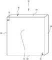
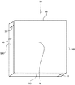
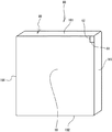
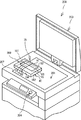
以下、本発明に係る表示端末装置1の実施形態について図面を参照して説明する。まず、表示端末装置1の物理的構成について、図1乃至図3を参照して説明する。図1は、表示端末装置1の正面側斜め上方から見た斜視図である。図2は、上側面181、左側面183および背面19に側面識別マークおよび背面識別マークが設けられた表示端末装置1の背面側斜め上方から見た斜視図である。図3は、下側面182、右側面184および背面19に側面識別マークおよび背面識別マークが設けられた表示端末装置1の背面側斜め下方から見た斜視図である。なお、図1において、紙面の左右方向が表示端末装置1の左右方向、紙面の上下方向が表示端末装置1の上下方向と定められている。   Hereinafter, an embodiment of a display terminal device 1 according to the present invention will be described with reference to the drawings. First, the physical configuration of the display terminal device 1 will be described with reference to FIGS. 1 to 3. FIG. 1 is a perspective view of the display terminal device 1 as seen from diagonally above the front side. FIG. 2 is a perspective view of the display terminal device 1 in which a side identification mark and a rear identification mark are provided on the upper side 181, the left side 183, and the rear side 19 as viewed obliquely from the rear side. FIG. 3 is a perspective view of the display terminal device 1 in which the side identification mark and the rear identification mark are provided on the lower side 182, the right side 184, and the rear surface 19 as viewed from obliquely below the rear side. In FIG. 1, the horizontal direction of the paper is defined as the horizontal direction of the display terminal device 1, and the vertical direction of the paper is defined as the vertical direction of the display terminal device 1.

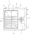
図1に示すように、表示端末装置1は正面17、上側面181、下側面182、左側面183、右側面184および背面19を有する略直方体形状の筐体40を備えている。表示端末装置1の正面17には情報を表示する平面視長方形状の表示画面10が設けられている。表示画面10のサイズは、例えばA5縦サイズであり、表示画面10の左上の角23が情報を表示する基準の位置である。表示画面10の短辺は、表示端末装置1の左右方向に形成され、表示画面10の長辺は、表示端末装置1の上下方向に形成される。そして、表示画面10の右側の長辺の中央の外周部24には、複数のボタンから構成される操作部20が設けられている。この操作部20は、ユーザが表示端末装置1に各種指示を入力するためのものである。また、図示しないが、表示端末装置1の左側面183にはメモリカード36(図4参照)を挿入する挿入口が設けられている。   As shown in FIG. 1, the display terminal device 1 includes a substantially rectangular parallelepiped housing 40 having a front surface 17, an upper side surface 181, a lower side surface 182, a left side surface 183, a right side surface 184 and a back surface 19. On the front surface 17 of the display terminal device 1, a display screen 10 having a rectangular shape in plan view for displaying information is provided. The size of the display screen 10 is, for example, A5 vertical size, and the upper left corner 23 of the display screen 10 is a reference position for displaying information. The short side of the display screen 10 is formed in the left-right direction of the display terminal device 1, and the long side of the display screen 10 is formed in the vertical direction of the display terminal device 1. An operation unit 20 including a plurality of buttons is provided on the outer peripheral portion 24 at the center of the long side on the right side of the display screen 10. The operation unit 20 is used by the user to input various instructions to the display terminal device 1. Although not shown, an insertion slot for inserting the memory card 36 (see FIG. 4) is provided on the left side surface 183 of the display terminal device 1.

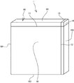
図2に示すように、表示端末装置1の背面19には、背面識別マーク11および12が設けられている。背面識別マーク11および12は、表示画面10(図1参照)の位置を表示端末装置1の背面19から示す直線状の識別マークである。なお、直線状の識別マークは印刷により形成しても良いし、溝状に形成しても良い。後述する他の識別マークについても同様である。背面識別マーク11は、表示画面10の上部の短辺21(図1参照)の位置を示す。具体的には、表示画面10を背面19に投影した場合に短辺21に対応する直線である。また、背面識別マーク12は、表示画面10の左側の長辺22(図1参照)の位置を示す。具体的には、表示画面10を背面19に投影した場合に長辺22に対応する直線である。背面識別マーク11および背面識別マーク12は、表示画面10の表示画面10を背面19に投影した場合に、表示画面10の左上の角23を示す位置で直交する。背面識別マーク11および背面識別マーク12は、それぞれ表示端末装置1の背面19の両端にまで到達している。   As shown in FIG. 2, back surface identification marks 11 and 12 are provided on the back surface 19 of the display terminal device 1. The rear identification marks 11 and 12 are linear identification marks indicating the position of the display screen 10 (see FIG. 1) from the rear surface 19 of the display terminal device 1. The linear identification mark may be formed by printing or may be formed in a groove shape. The same applies to other identification marks to be described later. The back identification mark 11 indicates the position of the short side 21 (see FIG. 1) at the top of the display screen 10. Specifically, it is a straight line corresponding to the short side 21 when the display screen 10 is projected on the back surface 19. The back identification mark 12 indicates the position of the long side 22 (see FIG. 1) on the left side of the display screen 10. Specifically, it is a straight line corresponding to the long side 22 when the display screen 10 is projected on the back surface 19. The rear identification mark 11 and the rear identification mark 12 are orthogonal to each other at a position indicating the upper left corner 23 of the display screen 10 when the display screen 10 of the display screen 10 is projected on the rear surface 19. The back identification mark 11 and the back identification mark 12 reach the both ends of the back surface 19 of the display terminal device 1, respectively.

また、図2および図3に示すように、表示端末装置1の上側面181、左側面183、右側面184および下側面182には、側面識別マーク13、14、15および16が設けられている。側面識別マーク13、14、15および16は、表示画面10の位置を表示端末装置1の側面181〜184から示す直線状の識別マークである。側面識別マーク13および16は、表示画面10の長辺22の位置を示す直線である。具体的には、側面識別マーク13および16は、表示画面10を背面19に投影した場合に、長辺22に対応する直線を上側面181および下側面182にまでそれぞれ延長した直線である。側面識別マーク14および15は、表示画面10の短辺の位置を示す直線である。具体的には、側面識別マーク14および15は、表示画面10を背面19に投影した場合に、短辺21に対応する直線を左側面183および右側面184にまでそれぞれ延長した直線である。側面識別マーク13、14、15および16は、背面識別マーク11および12と同様、それぞれ、表示端末装置1の側面181〜184の両端にまで到達しており、背面識別マーク11および12とつながっている。なお、詳細は後述するが、表示端末装置1の背面19および側面181〜184に設けられた識別マークは、表示画面10をコピー機100(図5参照)で複写する際の位置合わせに使用される。   Further, as shown in FIGS. 2 and 3, side identification marks 13, 14, 15 and 16 are provided on the upper side 181, the left side 183, the right side 184 and the lower side 182 of the display terminal device 1. . The side identification marks 13, 14, 15 and 16 are linear identification marks indicating the position of the display screen 10 from the side surfaces 181 to 184 of the display terminal device 1. The side identification marks 13 and 16 are straight lines indicating the position of the long side 22 of the display screen 10. Specifically, the side surface identification marks 13 and 16 are straight lines obtained by extending straight lines corresponding to the long side 22 to the upper side surface 181 and the lower side surface 182 when the display screen 10 is projected on the back surface 19. The side identification marks 14 and 15 are straight lines indicating the position of the short side of the display screen 10. Specifically, the side surface identification marks 14 and 15 are straight lines obtained by extending straight lines corresponding to the short sides 21 to the left side surface 183 and the right side surface 184 when the display screen 10 is projected on the back surface 19. Side identification marks 13, 14, 15, and 16 reach both ends of side surfaces 181 to 184 of display terminal device 1, and are connected to rear identification marks 11 and 12, similarly to rear identification marks 11 and 12. Yes. Although details will be described later, the identification marks provided on the back surface 19 and the side surfaces 181 to 184 of the display terminal device 1 are used for alignment when the display screen 10 is copied by the copy machine 100 (see FIG. 5). The

次に、表示端末装置1の電気的構成について、図4を参照して説明する。図4は、表示端末装置1の電気的構成を示すブロック図である。図4に示すように、この表示端末装置1は、表示端末装置1の制御を司るCPU31を備えている。CPU31には、バス38を介してROM32、RAM33、EEPROM34、表示画面10、メモリカードI/F35および操作部20が接続されている。そして、メモリカードI/F35には、メモリカード36が接続可能になっている。以下、CPU31、ROM32、RAM33、EEPROM34およびメモリカード36について説明する。   Next, the electrical configuration of the display terminal device 1 will be described with reference to FIG. FIG. 4 is a block diagram showing an electrical configuration of the display terminal device 1. As shown in FIG. 4, the display terminal device 1 includes a CPU 31 that controls the display terminal device 1. A ROM 32, a RAM 33, an EEPROM 34, a display screen 10, a memory card I / F 35, and an operation unit 20 are connected to the CPU 31 via a bus 38. A memory card 36 can be connected to the memory card I / F 35. Hereinafter, the CPU 31, ROM 32, RAM 33, EEPROM 34, and memory card 36 will be described.

CPU31は、表示端末装置1の主制御を司り、ROM32に記憶された制御プログラムに従って、表示端末装置1の表示画面10に画像を出力するための各種演算および処理を実行する。ROM32は、CPU31が実行するBIOS等のプログラムを記憶する読み出し専用の記憶装置である。RAM33は、任意に読み書き可能な記憶素子であり、ROM32やEEPROM34から読み出された各種設定値、CPU31が演算処理した演算結果を収容する各種記憶エリアが必要に応じて設けられている。EEPROM34は、読み書き可能な、電源を切ってもデータが消えない不揮発性記憶素子である。メモリカード36は、例えば、表示画面10に表示させる各種の情報(コンテンツ)を記憶する外部記憶媒体である。ユーザは、メモリカード36に記憶されたコンテンツや、外部からダウンロードしたコンテンツを表示画面10に表示させ、閲覧することができる。   The CPU 31 manages the main control of the display terminal device 1 and executes various calculations and processes for outputting an image on the display screen 10 of the display terminal device 1 according to a control program stored in the ROM 32. The ROM 32 is a read-only storage device that stores programs such as BIOS executed by the CPU 31. The RAM 33 is a storage element that can be arbitrarily read and written, and is provided with various storage areas for storing various setting values read from the ROM 32 and the EEPROM 34 and the calculation results calculated by the CPU 31 as necessary. The EEPROM 34 is a non-volatile storage element that can read and write and does not lose data even when the power is turned off. The memory card 36 is an external storage medium that stores various types of information (contents) to be displayed on the display screen 10, for example. The user can display and browse the content stored in the memory card 36 or the content downloaded from the outside on the display screen 10.

次に、図5および図6を参照して、ユーザが、コピー機100でコンテンツが表示された表示端末装置1の表示画面10(図1参照)を複写する場合の複写方法について説明する。図5は、表示端末装置1が原稿台101に載置されたコピー機100を右斜め上方から見た斜視図である。図6は、表示端末装置1が原稿台101に載置された状態で原稿カバー103が閉じられたコピー機100を左斜め上方から見た斜視図である。   Next, with reference to FIG. 5 and FIG. 6, a description will be given of a copying method when the user copies the display screen 10 (see FIG. 1) of the display terminal device 1 on which the content is displayed by the copying machine 100. FIG. FIG. 5 is a perspective view of the copying machine 100 with the display terminal device 1 placed on the document table 101 as viewed from the upper right side. FIG. 6 is a perspective view of the copying machine 100 in which the document cover 103 is closed with the display terminal device 1 placed on the document table 101 as viewed obliquely from the upper left.

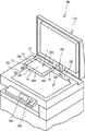
まず、図5を参照してコピー機100について説明する。図5に示すコピー機100は周知のコピー機であり、記録用紙などに画像、文字および記号などを複写することが可能なコピー機である。また、コピー機100は例示であり、複写機能の他、ファクシミリ機能、プリンタ機能およびスキャナ機能などを備えた複合機であっても良い。なお、図5において、紙面の左斜め下方向がコピー機100の正面方向、紙面の右斜め上方向がコピー機100の背面方向、紙面の右斜め下方向がコピー機100の右方向、および紙面の左斜め上方向がコピー機100の左方向と定められている。   First, the copier 100 will be described with reference to FIG. A copier 100 shown in FIG. 5 is a well-known copier, and is a copier capable of copying images, characters, symbols, and the like on a recording sheet or the like. Further, the copying machine 100 is an example, and may be a multifunction machine having a facsimile function, a printer function, a scanner function, and the like in addition to a copying function. In FIG. 5, the diagonally lower left direction of the paper is the front direction of the copier 100, the diagonally upper right direction of the paper is the rear direction of the copier 100, the diagonally lower right direction of the paper is the right direction of the copier 100, and the paper surface. Is defined as the left direction of the copier 100.

コピー機100の正面側には、複写の開始をコピー機100に指示するための複写ボタン104、および用紙サイズの設定、拡大・縮小率の設定などが可能な液晶パネル105が設けられている。そして、液晶パネル105の背面側には、透明なガラスで構成される平面視長方形状の原稿台101が設けられている。原稿台101には複写対象が載置される。また、原稿台101に載置された複写対象を押圧可能な原稿カバー103が、原稿台101に対して、蝶番102を介して回動開閉可能に設けられている。蝶番106は、コピー機100の上面の背面端部に設けられている。このコピー機100は端基準を採用している。端基準とは、原稿台101に複写対象を載置する際、複写対象を原稿台101の左側の短辺である短辺基準線107、および原稿台101の背面側の長辺である長辺基準線108とで構成される左奥の角に突き当てる方式を言う。   On the front side of the copier 100, a copy button 104 for instructing the copier 100 to start copying, and a liquid crystal panel 105 capable of setting a paper size, setting an enlargement / reduction ratio, and the like are provided. Further, on the back side of the liquid crystal panel 105, a document table 101 having a rectangular shape in plan view made of transparent glass is provided. A copy target is placed on the document table 101. A document cover 103 capable of pressing a copy target placed on the document table 101 is provided so as to be capable of rotating and opening with respect to the document table 101 via a hinge 102. The hinge 106 is provided at the rear end of the upper surface of the copier 100. This copier 100 employs an end reference. The edge reference is a short side reference line 107 that is the short side on the left side of the platen 101 and a long side that is a long side on the back side of the platen 101 when the copy target is placed on the platen 101. This is a method of hitting the left back corner formed by the reference line 108.

以下、表示端末装置1の表示画面10の複写方法について説明する。図5に示すように、ユーザは、表示端末装置1を原稿台101の左奥の角と重なる状態で、原稿台101と表示画面10(図1参照)とが対向するように原稿台101に載置する。このとき、原稿台101の上方から、表示端末装置1の背面19に設けられた背面識別マーク11および12と、原稿台101に設けられた短辺基準線107および長辺基準線108とを確認する。そして、背面識別マーク11と短辺基準線107とが直線でつながるように、また、背面識別マーク12と長辺基準線108とが直線でつながるように表示端末装置1の位置合わせを行う。なお、図5に示すように、表示端末装置1の右側面184に設けられた側面識別マーク15、および下側面182に設けられた側面識別マーク16を用いて、コピー機100の読取領域と、表示端末装置1の表示画面10との位置合わせを行うこともできる。   Hereinafter, a method for copying the display screen 10 of the display terminal device 1 will be described. As shown in FIG. 5, the user places the display terminal device 1 on the document table 101 so that the document table 101 and the display screen 10 (see FIG. 1) face each other in a state where the display terminal device 1 overlaps the left back corner of the document table 101. Place. At this time, the back side identification marks 11 and 12 provided on the back surface 19 of the display terminal device 1 and the short side reference line 107 and the long side reference line 108 provided on the document table 101 are confirmed from above the document table 101. To do. Then, the display terminal device 1 is aligned so that the back identification mark 11 and the short side reference line 107 are connected by a straight line, and the back identification mark 12 and the long side reference line 108 are connected by a straight line. As shown in FIG. 5, using the side identification mark 15 provided on the right side 184 and the side identification mark 16 provided on the lower side 182 of the display terminal device 1, the reading area of the copier 100, Position alignment with the display screen 10 of the display terminal device 1 can also be performed.

次いで、ユーザは、原稿カバー103を閉じる。ユーザは、表示画面10のサイズ(例えばA5)を把握している場合は、液晶パネル105に設けられたタッチパネルにより、表示画面10のサイズ(例えばA5)を用紙サイズとして設定する。そして、複写ボタン104を押下すると、表示画面10に表示された文字などの情報が用紙に複写される。この場合、前述したように、原稿台101の左奥の角と表示画面10の角の位置が適切に合わせられているので、複写されるのは表示画面10の領域のみとなる。なお、ユーザが表示画面10のサイズを把握していない場合は、原稿台101に設けられた目盛(A4R、A3など)を見て、筐体40の右側面184および下側面182の位置から適切な用紙サイズを選択すれば良い。また、コピー機100は、原稿カバー103を閉じることにより、原稿台101に載置された複写対象のサイズを検知して複写対象のサイズに適合する用紙サイズが自動的に選択される機能を備えている。この機能を利用する場合も、表示端末装置1の原稿台101に載置された部分よりも大きいサイズの用紙サイズが選択されるので、表示画面10を確実に全部複写することができる。   Next, the user closes the document cover 103. When the user knows the size of the display screen 10 (for example, A5), the user sets the size of the display screen 10 (for example, A5) as the paper size using the touch panel provided on the liquid crystal panel 105. When the copy button 104 is pressed, information such as characters displayed on the display screen 10 is copied onto the paper. In this case, as described above, since the position of the left back corner of the document table 101 and the corner of the display screen 10 are appropriately matched, only the area of the display screen 10 is copied. When the user does not know the size of the display screen 10, it is appropriate to look at the scales (A4R, A3, etc.) provided on the document table 101 from the positions of the right side 184 and the lower side 182 of the housing 40. Select a suitable paper size. The copier 100 also has a function of detecting the size of the copy target placed on the document table 101 by closing the document cover 103 and automatically selecting a paper size that matches the size of the copy target. ing. Even when this function is used, since a paper size larger than the part placed on the document table 101 of the display terminal device 1 is selected, the entire display screen 10 can be reliably copied.

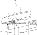
また、図6に示すように、原稿カバー103が閉じられた状態においても、表示端末装置1は厚みを有するため、僅かに原稿台101が視認可能である。この場合、表示端末装置1の背面19は視認困難であるが、側面181〜184は視認可能である。このような場合の表示端末装置1の位置合わせ方法について説明する。前述したように、表示端末装置1の右側面184には、側面識別マーク15が設けられ、下側面182(図5参照)には、側面識別マーク16が設けられている。よって、ユーザは、例えば、原稿カバー103を閉じた後に表示端末装置1の位置合わせを行う場合、又は原稿カバー103を閉じた際に表示端末装置1の位置がずれた場合に、側面識別マーク15および16を利用して位置合わせを行うことができる。具体的には、表示端末装置1の右側面184に設けられた側面識別マーク15、および下側面182に設けられた側面識別マーク16と、短辺基準線107および長辺基準線108とを確認する。そして、側面識別マーク15と短辺基準線107とが直線でつながるように、また、側面識別マーク16と長辺基準線108とが直線でつながるように表示端末装置1を移動する。   Further, as shown in FIG. 6, even when the document cover 103 is closed, the display terminal device 1 has a thickness, so that the document table 101 is slightly visible. In this case, the back surface 19 of the display terminal device 1 is difficult to see, but the side surfaces 181 to 184 are visible. A method for aligning the display terminal device 1 in such a case will be described. As described above, the side identification mark 15 is provided on the right side 184 of the display terminal device 1, and the side identification mark 16 is provided on the lower side 182 (see FIG. 5). Therefore, for example, when the user aligns the display terminal device 1 after closing the document cover 103 or when the position of the display terminal device 1 is shifted when the document cover 103 is closed, the side identification mark 15 And 16 can be used for alignment. Specifically, the side identification mark 15 provided on the right side 184 of the display terminal device 1, the side identification mark 16 provided on the lower side 182, the short side reference line 107 and the long side reference line 108 are confirmed. To do. Then, the display terminal device 1 is moved so that the side identification mark 15 and the short side reference line 107 are connected by a straight line, and the side identification mark 16 and the long side reference line 108 are connected by a straight line.

このように、表示端末装置1の背面19が視認困難な場合でも、側面181〜184に設けられた識別マークにより、コピー機100の読取領域と、表示端末装置1の表示画面10との位置合わせを容易に行うことができる。なお、例えば、図6に示すように、コピー機100の側面に原稿台101の長辺基準線108、短辺基準線107の位置を示す目印である側面合わせマーク110および120が設けられていれば、コピー機100の読取領域と、表示端末装置1の表示画面10との位置合わせをさらに容易に行うことができる。   As described above, even when the back surface 19 of the display terminal device 1 is difficult to visually recognize, alignment between the reading area of the copy machine 100 and the display screen 10 of the display terminal device 1 is performed by the identification marks provided on the side surfaces 181 to 184. Can be easily performed. For example, as shown in FIG. 6, side alignment marks 110 and 120 which are marks indicating the positions of the long side reference line 108 and the short side reference line 107 of the document table 101 are provided on the side surface of the copying machine 100. For example, the reading area of the copying machine 100 and the display screen 10 of the display terminal device 1 can be more easily aligned.

このように、識別マーク(11乃至16)を利用すれば、原稿台101に表示端末装置1を載置する際、表示画面10の全体を確実に複写できる最適な位置に表示端末装置1を合わせることができる。そして、ユーザが表示画面10の大きさを把握している場合は、表示画面10のみを複写することができ、複写結果の見栄えも良い。また、表示画面10の識別マークを直線で形成することにより、簡便に低コストで識別マークを構成することができる。   As described above, when the identification mark (11 to 16) is used, when the display terminal device 1 is placed on the document table 101, the display terminal device 1 is adjusted to an optimum position where the entire display screen 10 can be reliably copied. be able to. When the user knows the size of the display screen 10, only the display screen 10 can be copied, and the appearance of the copy result is good. Moreover, by forming the identification mark on the display screen 10 with a straight line, the identification mark can be configured easily and at low cost.

以下に、図7乃至14を参照して、背面19および側面181〜184の少なくとも一方に識別マークを設けた他の実施形態について説明する。   Hereinafter, another embodiment in which an identification mark is provided on at least one of the back surface 19 and the side surfaces 181 to 184 will be described with reference to FIGS.

図7に示すように、表示端末装置50の背面19のみに矢印識別マーク51および52が設けられていても良い。図7は、背面19に矢印識別マーク51および52が設けられた表示端末装置50の背面側斜め上方から見た斜視図である。表示端末装置50の背面19には、表示画面10(図1参照)の位置を矢印で示す矢印識別マーク51および52が設けられている。具体的には、矢印識別マーク51は、前述の背面識別マーク11と同様、表示画面10の短辺21(図1参照)の位置を示し、背面19の右側面184(図3参照)と接する側の端を指す矢印である。矢印識別マーク52は、前述の背面識別マーク12と同様、表示画面10の長辺22(図1参照)の位置を示し、背面19の下側面182(図3参照)と接する側の端を指す矢印である。   As shown in FIG. 7, arrow identification marks 51 and 52 may be provided only on the back surface 19 of the display terminal device 50. FIG. 7 is a perspective view of the display terminal device 50 in which the arrow identification marks 51 and 52 are provided on the back surface 19 as viewed from obliquely upward on the back surface side. On the back surface 19 of the display terminal device 50, there are provided arrow identification marks 51 and 52 that indicate the position of the display screen 10 (see FIG. 1) with arrows. Specifically, the arrow identification mark 51 indicates the position of the short side 21 (see FIG. 1) of the display screen 10 and is in contact with the right side surface 184 (see FIG. 3) of the back surface 19 in the same manner as the back identification mark 11 described above. It is an arrow pointing to the end on the side. The arrow identification mark 52 indicates the position of the long side 22 (see FIG. 1) of the display screen 10 and indicates the end on the side in contact with the lower side surface 182 (see FIG. 3) of the back surface 19 in the same manner as the back identification mark 12 described above. It is an arrow.

表示端末装置50の表示画面10を複写する場合、ユーザは、矢印識別マーク51と短辺基準線107とが直線でつながるように、また、矢印識別マーク52と長辺基準線108とが直線でつながるように表示端末装置50の位置を合わせれば良い。このように、矢印で表示端末装置50の表示画面10の短辺21および長辺22の位置を示すことで、ユーザは表示画面の位置を容易に把握でき、コピー機100の読取領域と表示画面10との位置合わせを容易に行うことができる。   When copying the display screen 10 of the display terminal device 50, the user connects the arrow identification mark 51 and the short side reference line 107 with a straight line, and the arrow identification mark 52 and the long side reference line 108 with a straight line. The position of the display terminal device 50 may be adjusted so as to be connected. Thus, by indicating the positions of the short side 21 and the long side 22 of the display screen 10 of the display terminal device 50 with the arrows, the user can easily grasp the position of the display screen, and the reading area of the copier 100 and the display screen 10 can be easily aligned.

また、図8に示すように、表示端末装置55の側面(182および184)のみに識別マークが設けられていても良い。図8は、右側面184および下側面182にそれぞれ側面識別マーク56および57が設けられた表示端末装置55の背面側斜め下方から見た斜視図である。表示端末装置55の右側面184および下側面182には、表示画面10(図1参照)の位置を示す直線状の側面識別マーク56および57が設けられている。側面識別マーク56は表示画面10の短辺21の位置を示し、側面識別マーク57は表示画面10の長辺22の位置を示す。また、側面識別マーク56および57は、それぞれ表示端末装置55の右側面184および下側面182の両端にまで到達している。つまり、側面識別マーク56および57は、前述の側面識別マーク15および16と同一の構成を有する。よって、表示端末装置55の複写方法については、図6を参照して説明した側面識別マーク15および16を用いた複写方法と同様であるため、説明は省略する。   Moreover, as shown in FIG. 8, the identification mark may be provided only in the side surface (182 and 184) of the display terminal device 55. FIG. FIG. 8 is a perspective view of the display terminal device 55 provided with side surface identification marks 56 and 57 on the right side surface 184 and the lower side surface 182 respectively, as viewed from the lower rear side. On the right side surface 184 and the lower side surface 182 of the display terminal device 55, linear side surface identification marks 56 and 57 indicating the position of the display screen 10 (see FIG. 1) are provided. The side identification mark 56 indicates the position of the short side 21 of the display screen 10, and the side identification mark 57 indicates the position of the long side 22 of the display screen 10. Further, the side identification marks 56 and 57 reach both ends of the right side 184 and the lower side 182 of the display terminal device 55, respectively. That is, the side identification marks 56 and 57 have the same configuration as the side identification marks 15 and 16 described above. Therefore, the copying method of the display terminal device 55 is the same as the copying method using the side identification marks 15 and 16 described with reference to FIG.

このように、表示端末装置55の側面(182および184)のみに識別マークを設けることによっても、容易にコピー機100の読取領域と、表示端末装置55の表示画面10との位置合わせを行うことができる。   As described above, the reading area of the copier 100 and the display screen 10 of the display terminal device 55 can be easily aligned by providing the identification marks only on the side surfaces (182 and 184) of the display terminal device 55. Can do.

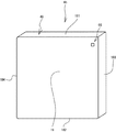
また、図9に示すように表示端末装置60の背面19に背面識別マーク61および62が設けられていても良い。図9は、背面19に背面識別マーク61および62が設けられた表示端末装置60の背面側斜め上方から見た斜視図である。表示端末装置60の背面19には、表示画面10(図1参照)の位置を直線状に示す背面識別マーク61および62が設けられている。具体的には、背面識別マーク61は、表示画面10の短辺21(図1参照)の位置を示し、表示画面10の左上の角23(図1参照)を示す位置から、背面19の上端部に到達する直線である。背面識別マーク62は、表示画面10の長辺22(図1参照)の位置を示し、表示画面10の左上の角23を示す位置から、背面19の左端部に到達する直線である。よって、表示画面10の左上の角23を示す位置において、背面識別マーク61および62は直角を形成している。   Further, as shown in FIG. 9, back surface identification marks 61 and 62 may be provided on the back surface 19 of the display terminal device 60. FIG. 9 is a perspective view of the display terminal device 60 in which the back surface identification marks 61 and 62 are provided on the back surface 19 as viewed from obliquely upward on the back surface side. On the back surface 19 of the display terminal device 60, back surface identification marks 61 and 62 are provided that indicate the position of the display screen 10 (see FIG. 1) in a straight line. Specifically, the back surface identification mark 61 indicates the position of the short side 21 (see FIG. 1) of the display screen 10, and the upper end of the back surface 19 from the position indicating the upper left corner 23 (see FIG. 1) of the display screen 10. It is a straight line that reaches the part. The back identification mark 62 is a straight line that indicates the position of the long side 22 (see FIG. 1) of the display screen 10 and reaches the left end portion of the back surface 19 from the position that indicates the upper left corner 23 of the display screen 10. Therefore, the back identification marks 61 and 62 form a right angle at the position indicating the upper left corner 23 of the display screen 10.

表示端末装置60の表示画面10を複写する場合、ユーザは、原稿台101の上方から見て、背面識別マーク61および62で形成される、表示端末装置60の表示画面10の左上の角23を示す角が、原稿台101の左奥の角と重なるように、表示端末装置60の位置を合わせれば良い。   When copying the display screen 10 of the display terminal device 60, the user views the upper left corner 23 of the display screen 10 of the display terminal device 60, which is formed by the back identification marks 61 and 62 when viewed from above the document table 101. The position of the display terminal device 60 may be aligned so that the corner shown overlaps the corner on the left back of the document table 101.

このように、表示端末装置60の背面19に設けられた背面識別マーク61および62で表示画面10の左上の角23の位置を示すことで、ユーザは、表示画面10の位置を容易に把握でき、コピー機100の読取領域と表示端末装置60の表示画面10との位置合わせを容易に行うことがきる。   Thus, the user can easily grasp the position of the display screen 10 by indicating the position of the upper left corner 23 of the display screen 10 by the back surface identification marks 61 and 62 provided on the back surface 19 of the display terminal device 60. Thus, it is possible to easily align the reading area of the copier 100 and the display screen 10 of the display terminal device 60.

また、図10に示すように表示端末装置65の背面19に正方形識別マーク66が設けられていても良い。図10は、背面19に正方形識別マーク66が設けられた表示端末装置65の背面側斜め上方から見た斜視図である。表示端末装置65の背面19には、表示画面10(図1参照)の位置を示す正方形状の正方形識別マーク66が設けられている。正方形識別マーク66は、例えば1cm角の正方形の外形を示す線である。   Further, as shown in FIG. 10, a square identification mark 66 may be provided on the back surface 19 of the display terminal device 65. FIG. 10 is a perspective view of the display terminal device 65 in which the square identification mark 66 is provided on the back surface 19 as viewed obliquely from above the back surface side. On the back surface 19 of the display terminal device 65, a square-shaped square identification mark 66 indicating the position of the display screen 10 (see FIG. 1) is provided. The square identification mark 66 is a line indicating the outer shape of a square of 1 cm square, for example.

次に、表示端末装置65の表示画面10を複写する場合、ユーザは、原稿台101の上方から見て、正方形識別マーク66と原稿台101の左奥の角とが重なるように、表示端末装置60の位置を合わせれば良い。   Next, when copying the display screen 10 of the display terminal device 65, the user views the display terminal device so that the square identification mark 66 and the left back corner of the document table 101 overlap when viewed from above the document table 101. 60 positions may be aligned.

このように、正方形で表示端末装置65の表示画面10の左上の角23の位置を示すことで、ユーザは、コピー機100の読取領域と表示端末装置65の表示画面10の位置合わせを容易に行うことができる。   Thus, the user can easily align the reading area of the copy machine 100 and the display screen 10 of the display terminal device 65 by indicating the position of the upper left corner 23 of the display screen 10 of the display terminal device 65 with a square. It can be carried out.

また、図11に示すように表示端末装置70の背面19に十字識別マーク71および正方形識別マーク72が設けられていても良い。図11は、背面19に十字識別マーク71および正方形識別マーク72が設けられた表示端末装置70の背面側斜め上方から見た斜視図である。表示端末装置70の背面19には表示端末装置70の表示画面10(図1参照)の左上の角23の位置を示す十字識別マーク71、および表示端末装置70の表示画面10の右下の角25(図1参照)の位置を示す正方形識別マーク72が設けられている。十字識別マーク71は、十字に交差する、例えば各1cm程度の長さを有する2本の直線から構成される。正方形識別マーク72は、図10に示した正方形識別マーク66と同様のマークである。   In addition, as shown in FIG. 11, a cross identification mark 71 and a square identification mark 72 may be provided on the back surface 19 of the display terminal device 70. FIG. 11 is a perspective view of the display terminal device 70 in which the cross identification mark 71 and the square identification mark 72 are provided on the back surface 19 as viewed obliquely from the back side. On the back surface 19 of the display terminal device 70, a cross identification mark 71 indicating the position of the upper left corner 23 of the display screen 10 (see FIG. 1) of the display terminal device 70, and a lower right corner of the display screen 10 of the display terminal device 70. A square identification mark 72 indicating the position 25 (see FIG. 1) is provided. The cross identification mark 71 is composed of two straight lines each having a length of about 1 cm, for example, crossing the cross. The square identification mark 72 is a mark similar to the square identification mark 66 shown in FIG.

表示端末装置70の表示画面を複写する場合、ユーザは、原稿台101の上方から見て、十字識別マーク71と原稿台101の左奥の角とが重なるように、表示端末装置70を位置合わせすれば良い。さらに、ユーザは、表示端末装置65の背面から正方形識別マーク72により表示画面10の右下の角25の位置を把握できる。よって、ユーザは、予め表示画面10のサイズを把握していなくても、「A4R」および「A3」などの用紙サイズを示す、原稿台101の外周部に設けられた表示と、正方形識別マーク72とを比較することにより、表示端末装置70の背面19から表示画面10のサイズを確認することができる。この場合、ユーザは、最適な用紙サイズを指定することにより、表示画面10のみを複写できる。また、ユーザは、表示画面10のサイズが分かるので、拡大・縮小時の倍率を適切に指定することができる。   When copying the display screen of the display terminal device 70, the user aligns the display terminal device 70 so that the cross identification mark 71 and the left back corner of the document table 101 overlap when viewed from above the document table 101. Just do it. Further, the user can grasp the position of the lower right corner 25 of the display screen 10 by the square identification mark 72 from the back surface of the display terminal device 65. Therefore, even if the user does not know the size of the display screen 10 in advance, the display provided on the outer peripheral portion of the document table 101 indicating the paper size such as “A4R” and “A3”, and the square identification mark 72. , The size of the display screen 10 can be confirmed from the back surface 19 of the display terminal device 70. In this case, the user can copy only the display screen 10 by designating an optimal paper size. In addition, since the user knows the size of the display screen 10, the user can appropriately specify the magnification at the time of enlargement / reduction.

また、表示端末装置70に設けられる識別マークを表示端末装置70の上下方向で異なる識別マーク(十字識別マーク71および正方形識別マーク72)とすることで、ユーザは、表示端末装置70の上下方向を表示端末装置70の背面19から容易に把握することができる。これにより、表示画面10を最適な位置で複写することができる。   In addition, by using different identification marks (cross identification mark 71 and square identification mark 72) in the vertical direction of the display terminal device 70, the user can change the vertical direction of the display terminal device 70. It can be easily grasped from the back surface 19 of the display terminal device 70. Thereby, the display screen 10 can be copied at an optimum position.

また、図12に示すように、表示端末装置85に表示画面10(図1参照)の輪郭線を示す凹部識別マーク86が設けられていても良い。図12は、背面19に凹部識別マーク86が設けられた表示端末装置85の背面側斜め上方から見た斜視図である。表示端末装置85の背面19には、表示画面10の全体の位置を示し、筐体40の外面に対して凹部として形成されている背面視長方形状の凹部識別マーク86が設けられている。具体的には、凹部識別マーク86は、表示画面10を背面19に投影した場合に、表示画面10の輪郭線で囲まれる凹部である。なお、凹部識別マーク86は、表示画面10の短辺21を示す短辺87、および表示画面10の長辺22を示す長辺88を有している。   In addition, as shown in FIG. 12, the display terminal device 85 may be provided with a recess identification mark 86 indicating the outline of the display screen 10 (see FIG. 1). FIG. 12 is a perspective view of the display terminal device 85 in which the recessed portion identification mark 86 is provided on the back surface 19 as seen from the obliquely upper side on the back surface side. A rear surface 19 of the display terminal device 85 is provided with a concave portion identification mark 86 that indicates the overall position of the display screen 10 and is formed as a concave portion with respect to the outer surface of the housing 40 in a rear view. Specifically, the recess identification mark 86 is a recess surrounded by the outline of the display screen 10 when the display screen 10 is projected on the back surface 19. The recess identification mark 86 has a short side 87 indicating the short side 21 of the display screen 10 and a long side 88 indicating the long side 22 of the display screen 10.

表示端末装置85の表示画面10を複写する場合、原稿台101の上方から見て、凹部識別マーク86の背面視で右上の角と、原稿台101の左奥の角とが重なるように、表示端末装置85を載置する。この時、ユーザは、短辺87と短辺基準線107(図5参照)とが同一直線上に載るように、また、長辺88と長辺基準線108(図5参照)とが同一直線上に載るように表示端末装置85の位置合わせを行えば良い。   When the display screen 10 of the display terminal device 85 is copied, the display is made so that the upper right corner and the left rear corner of the document table 101 overlap with each other when viewed from the back of the recess identification mark 86 when viewed from above the document table 101. The terminal device 85 is placed. At this time, the user places the short side 87 and the short side reference line 107 (see FIG. 5) on the same straight line, and the long side 88 and the long side reference line 108 (see FIG. 5) have the same straight line. The display terminal device 85 may be aligned so as to be placed on the line.

このように、凹部識別マーク86により表示端末装置85の表示画面10の輪郭線を示すことで、ユーザは、明確に表示画面10の位置を把握できる。そして、コピー機100の読取領域と、表示端末装置85の表示画面との位置合わせを容易に行うことができる。また、凹部識別マーク86は凹形状である。よって、コピー機100の原稿台101と表示端末装置85の表示画面10とが対向するように表示端末装置を載置し、原稿カバー103(図5参照)を閉じた時に、凹部識別マーク86と原稿カバー103とが干渉することなく、原稿カバー103を安定して閉じることができる。   Thus, the user can clearly grasp the position of the display screen 10 by indicating the contour line of the display screen 10 of the display terminal device 85 by the recess identification mark 86. Then, it is possible to easily align the reading area of the copier 100 and the display screen of the display terminal device 85. Moreover, the recessed part identification mark 86 is concave shape. Therefore, when the display terminal device is placed so that the document table 101 of the copier 100 and the display screen 10 of the display terminal device 85 face each other and the document cover 103 (see FIG. 5) is closed, the recess identification mark 86 and The document cover 103 can be stably closed without interfering with the document cover 103.

また、図13に示すように、表示端末装置75の背面19および側面181〜184に表示画面10(図1参照)の外形および中心26(図1参照)の位置を示す識別マークが設けられていても良い。図13は、背面19および上側面181および左側面183に表示画面10の外形および中心26の位置を示す識別マークが設けられた表示端末装置75の背面側斜め上方から見た斜視図である。表示端末装置75の背面19には、表示画面10の長手方向の中心の位置を示す直線状の背面横中心識別マーク76、表示画面10の短手方向の中心の位置を示す直線状の背面縦中心識別マーク77が設けられている。具体的には、背面横中心識別マーク76は、表示画面10を背面19に投影した場合に表示画面10の長手方向の中心線に対応する直線である。背面縦中心識別マーク77は、表示画面10を背面19に投影した場合に表示画面10の短手方向の中心線に対応する直線である。よって、背面横中心識別マーク76および背面縦中心識別マーク77は、表示画面10の中心26に対応する位置で直交する。また、表示端末装置75の背面19には、表示画面10の輪郭線を示す輪郭識別マーク91が設けられている。具体的には、輪郭識別マーク91は、表示画面10を背面19に投影した場合に表示画面10の輪郭線に対応する線である。   Further, as shown in FIG. 13, an identification mark indicating the outer shape of the display screen 10 (see FIG. 1) and the position of the center 26 (see FIG. 1) is provided on the back surface 19 and the side surfaces 181 to 184 of the display terminal device 75. May be. FIG. 13 is a perspective view of the display terminal device 75 as viewed obliquely from above on the back side in which the rear face 19, the upper side face 181 and the left side face 183 are provided with identification marks indicating the outer shape of the display screen 10 and the position of the center 26. On the back surface 19 of the display terminal device 75, a straight back side lateral center identification mark 76 indicating the center position in the longitudinal direction of the display screen 10, and a straight back surface length indicating the center position in the short direction of the display screen 10. A center identification mark 77 is provided. Specifically, the back lateral center identification mark 76 is a straight line corresponding to the longitudinal center line of the display screen 10 when the display screen 10 is projected onto the back surface 19. The back vertical center identification mark 77 is a straight line corresponding to the center line in the short direction of the display screen 10 when the display screen 10 is projected onto the back surface 19. Therefore, the back horizontal center identification mark 76 and the back vertical center identification mark 77 are orthogonal to each other at a position corresponding to the center 26 of the display screen 10. Further, on the back surface 19 of the display terminal device 75, an outline identification mark 91 indicating the outline of the display screen 10 is provided. Specifically, the contour identification mark 91 is a line corresponding to the contour line of the display screen 10 when the display screen 10 is projected on the back surface 19.

そして、表示端末装置75の上側面181および左側面183にはそれぞれ、側面縦中心識別マーク79および側面横中心識別マーク78が設けられている。また、図13に示すように、表示端末装置75の下側面182および右側面184にはそれぞれ、側面縦中心識別マーク83および側面横中心識別マーク82が設けられている。   And the side surface vertical center identification mark 79 and the side surface horizontal center identification mark 78 are provided in the upper side surface 181 and the left side surface 183 of the display terminal device 75, respectively. Further, as shown in FIG. 13, a lateral vertical center identification mark 83 and a lateral lateral center identification mark 82 are provided on the lower side surface 182 and the right side surface 184 of the display terminal device 75, respectively.

次に、図14を参照して、表示端末装置75の表示画面10の複写方法について説明する。図14は、表示端末装置75が原稿台201に載置されたコピー機200を右斜め上方から見た斜視図である。図14に示すコピー機200の原稿台201は中央基準を採用している。中央基準とは、原稿台201に複写対象を載置する際、原稿台201の左側の短辺の直線である短辺基準線207の中央の目印の中央線209と、短辺基準線207に当接される複写対象の一辺の中央とを合わせる方式を言う。   Next, a method for copying the display screen 10 of the display terminal device 75 will be described with reference to FIG. FIG. 14 is a perspective view of the copier 200 on which the display terminal device 75 is placed on the document table 201 as viewed obliquely from the upper right. The document table 201 of the copier 200 shown in FIG. The center reference refers to the center line 209 of the center of the short side reference line 207 that is a straight line on the left side of the document table 201 and the short side reference line 207 when the copy target is placed on the document table 201. A method of matching the center of one side of the copy object to be abutted.

以下、表示端末装置75の表示画面10の複写方法について説明する。図14に示すように、ユーザは、表示端末装置1を原稿台201の短辺基準線207と重なる状態で、原稿台201と表示画面10(図1参照)とが対向するように原稿台201に載置する。このとき、原稿台201の上方から、表示端末装置75の背面に設けられた輪郭識別マーク91および背面縦中心識別マーク77と、原稿台201に設けられた短辺基準線207および中央線209とを確認する。そして、輪郭識別マーク91の上辺部分と短辺基準線207とが直線でつながるように、また、背面縦中心識別マーク77と中央線209とが直線でつながるように、表示端末装置75の位置合わせを行う。そして、ユーザは原稿カバー203を閉じ、複写ボタン204を押下することにより複写を行う。   Hereinafter, a method for copying the display screen 10 of the display terminal device 75 will be described. As shown in FIG. 14, the user places the display terminal device 1 on the document table 201 so that the document table 201 and the display screen 10 (see FIG. 1) face each other in a state where the display terminal device 1 overlaps the short side reference line 207 of the document table 201. Placed on. At this time, from above the document table 201, the contour identification mark 91 and the back vertical center identification mark 77 provided on the back surface of the display terminal device 75, the short side reference line 207 and the center line 209 provided on the document table 201, Confirm. Then, alignment of the display terminal device 75 is performed so that the upper side portion of the contour identification mark 91 and the short side reference line 207 are connected by a straight line, and the back vertical center identification mark 77 and the center line 209 are connected by a straight line. I do. The user then closes the document cover 203 and presses the copy button 204 to perform copying.

このように、表示画面10の中心26の位置を示す識別マークを有する表示端末装置75を用いることにより、中央基準のコピー機200にも対応でき、コピー機200の読取領域と、表示端末装置75の表示画面10との位置合わせを行うことができる。また、表示端末装置75の側面181〜184にも、表示画面10の中心26の位置を示す識別マークが設けられている。側面縦中心識別マーク79(図13参照)を用いれば、原稿カバー203が閉じられ、表示端末装置75の背面19が視認困難な場合でも中央基準のコピー機200において、コピー機200の読取領域と表示画面10の位置合わせを行うことができる。   As described above, by using the display terminal device 75 having the identification mark indicating the position of the center 26 of the display screen 10, it is possible to cope with the central reference copy machine 200, the reading area of the copy machine 200, and the display terminal device 75. Can be aligned with the display screen 10. Further, identification marks indicating the position of the center 26 of the display screen 10 are also provided on the side surfaces 181 to 184 of the display terminal device 75. If the side vertical center identification mark 79 (see FIG. 13) is used, even if the document cover 203 is closed and the back surface 19 of the display terminal device 75 is difficult to see, The display screen 10 can be aligned.

さらに、輪郭識別マーク91を用いれば、図5に示す端基準のコピー機100においても、コピー機100の読取領域と表示画面10の位置合わせを行うこともできる。つまり、表示端末装置75は、コピー機の端基準および中央基準を問わず用いることができる。よって、表示端末装置75を用いることにより、ユーザは、自分にとって位置合わせをし易い識別マークを選択して位置合わせを行うことができる。   Further, if the contour identification mark 91 is used, the reading area of the copier 100 and the display screen 10 can be aligned even in the end-reference copier 100 shown in FIG. That is, the display terminal device 75 can be used regardless of the end reference and the center reference of the copier. Therefore, by using the display terminal device 75, the user can perform alignment by selecting an identification mark that is easy for the user to align.

なお、図1に示す短辺21および長辺22が、本発明の「隣り合う二辺」に相当し、図14に示す凹部識別マーク86が、本発明の「凹部」に相当する。   The short side 21 and the long side 22 shown in FIG. 1 correspond to “two adjacent sides” of the present invention, and the concave identifying mark 86 shown in FIG. 14 corresponds to the “concave” of the present invention.

なお、上記の実施形態に示される表示端末装置の構成は例示であり、本発明は各種の変形が可能なことはいうまでもない。   The configuration of the display terminal device shown in the above embodiment is an exemplification, and it goes without saying that the present invention can be variously modified.

前述の実施の形態では、表示端末装置1は、正面17、側面(181〜184)および背面19を有する略直方体形状であったが、図15に示すように、実質的に側面が存在しないシート状の表示端末装置90であっても良い。図15は、変形例に係る表示端末装置90の斜視図である。表示端末装置90は表面27および裏面29から形成され、実質的に側面を有さない平面視長方形状である。そして、コピー機100(図5参照)の読取領域と、表示端末装置90の表示画面10(図1参照)との位置合わせを行うための識別マークは、裏面29にのみ設けられる。この場合、識別マークは、表示画面10の短辺21(図1参照)および長辺22(図1参照)を示す直線状の識別マークでも良いし、表示画面10の中心26を示す識別マークでも良いし、表示画面10の輪郭線を示す識別マークでも良い。また、表示画面10の四つの角のうち少なくとも1つを示す識別マークでも良い。   In the above-described embodiment, the display terminal device 1 has a substantially rectangular parallelepiped shape having the front surface 17, the side surfaces (181 to 184), and the back surface 19. However, as shown in FIG. 15, the sheet has substantially no side surface. Display terminal device 90 may be used. FIG. 15 is a perspective view of a display terminal device 90 according to a modification. The display terminal device 90 is formed from the front surface 27 and the back surface 29, and has a rectangular shape in plan view substantially having no side surface. An identification mark for aligning the reading area of the copier 100 (see FIG. 5) with the display screen 10 (see FIG. 1) of the display terminal device 90 is provided only on the back surface 29. In this case, the identification mark may be a linear identification mark indicating the short side 21 (see FIG. 1) and the long side 22 (see FIG. 1) of the display screen 10, or may be an identification mark indicating the center 26 of the display screen 10. Alternatively, an identification mark indicating the outline of the display screen 10 may be used. Further, an identification mark indicating at least one of the four corners of the display screen 10 may be used.

また、前述の実施形態では、正方形識別マーク66および72は、約1cm角の正方形であったが、正方形の一辺の長さは1cmに限らない。また、前述の実施形態では、表示画面10の角を示す識別マークは、十字および正方形であったが、形状はこれに限らない。例えば、長方形、三角形、平行四辺形およびひし形などでも良い。   In the above-described embodiment, the square identification marks 66 and 72 are approximately 1 cm square, but the length of one side of the square is not limited to 1 cm. In the above-described embodiment, the identification marks indicating the corners of the display screen 10 are crosses and squares, but the shape is not limited thereto. For example, a rectangle, a triangle, a parallelogram, and a rhombus may be used.

また、前述の実施形態では、表示画面10の位置を直線で示す識別マークは、背面19又は側面181〜184の端部の両端まで到達していたが、直線で示す識別マークは、背面19又は側面181〜184の端部の片方にのみ到達していても良い。   In the above-described embodiment, the identification mark that indicates the position of the display screen 10 with a straight line has reached both ends of the rear surface 19 or the end portions of the side surfaces 181 to 184. It may reach only one of the end portions of the side surfaces 181 to 184.

また、前述の実施形態では、表示画面10の上下方向で異なる形状の識別マークを付すことを1つの例として説明したが、識別マークを上下、同形状にして、色を異なるものとしても良い。   In the above-described embodiment, the identification marks having different shapes in the vertical direction of the display screen 10 have been described as one example. However, the identification marks may be formed in the same shape in the vertical direction and the colors may be different.

表示端末装置1の正面側斜め上方から見た斜視図である。FIG. 3 is a perspective view of the display terminal device 1 as viewed from diagonally above the front side. 上側面181、左側面183および背面19に側面識別マークおよび背面識別マークが設けられた表示端末装置1の背面側斜め上方から見た斜視図である。FIG. 3 is a perspective view of the display terminal device 1 in which a side identification mark and a rear identification mark are provided on an upper side 181, a left side 183, and a back side 19 when viewed from obliquely upward on the back side. 下側面182、右側面184および背面19に側面識別マークおよび背面識別マークが設けられた表示端末装置1の背面側斜め下方から見た斜視図である。It is the perspective view seen from the back side slanting lower part of the display terminal device 1 by which the side surface identification mark and the back surface identification mark were provided in the lower surface 182, the right surface 184, and the back surface 19. 表示端末装置1の電気的構成を示すブロック図である。3 is a block diagram showing an electrical configuration of the display terminal device 1. FIG. 表示端末装置1が原稿台101に載置されたコピー機100を右斜め上方から見た斜視図である。FIG. 2 is a perspective view of the copy terminal 100 with the display terminal device 1 placed on the document table 101 as viewed obliquely from the upper right. 表示端末装置1が原稿台101に載置された状態で原稿カバー103が閉じられたコピー機100を左斜め上方から見た斜視図である。FIG. 2 is a perspective view of the copier 100 with the document cover 103 closed with the display terminal device 1 placed on the document table 101, as viewed obliquely from the upper left. 背面19に矢印識別マーク51および52が設けられた表示端末装置50の背面側斜め上方から見た斜視図である。It is the perspective view seen from the back side slanting upper part of the display terminal device 50 by which the arrow identification marks 51 and 52 were provided in the back surface 19. FIG. 下側面182および右側面184にそれぞれ側面識別マーク56および57が設けられた表示端末装置55の背面側斜め下方から見た斜視図である。It is the perspective view seen from the back side slanting lower part of the display terminal device 55 by which the side surface identification marks 56 and 57 were provided in the lower surface 182 and the right side 184, respectively. 背面19に背面識別マーク61および62が設けられた表示端末装置60の背面側斜め上方から見た斜視図である。It is the perspective view seen from the back side slanting upper part of the display terminal device 60 in which the back surface identification mark 61 and 62 was provided in the back surface 19. FIG. 背面19に正方形識別マーク66が設けられた表示端末装置65の背面側斜め上方から見た斜視図である。It is the perspective view seen from the back side slanting upper part of the display terminal device 65 by which the square identification mark 66 was provided in the back surface 19. FIG. 背面19に十字識別マーク71および正方形識別マーク72が設けられた表示端末装置70の背面側斜め上方から見た斜視図である。It is the perspective view seen from the back side slanting upper part of the display terminal device 70 in which the cross identification mark 71 and the square identification mark 72 were provided in the back surface 19. FIG. 背面19に凹部識別マーク86が設けられた表示端末装置85の背面側斜め上方から見た斜視図である。It is the perspective view seen from the back side slanting upper part of the display terminal device 85 by which the recessed part identification mark 86 was provided in the back surface 19. FIG. 背面19および上側面181および左側面183に表示画面10の外形および中心26の位置を示す識別マークが設けられた表示端末装置75の背面側斜め上方から見た斜視図である。7 is a perspective view of the display terminal device 75 as viewed from diagonally above on the back side in which an identification mark indicating the outer shape of the display screen 10 and the position of the center 26 is provided on the back surface 19, the upper side surface 181 and the left side surface 183. FIG. 表示端末装置75が原稿台201に載置されたコピー機200を右斜め上方から見た斜視図である。FIG. 3 is a perspective view of the copy machine 200 with the display terminal device 75 placed on the document table 201 as viewed from the upper right side. 変形例に係る表示端末装置90の斜視図である。It is a perspective view of the display terminal device 90 which concerns on a modification.

符号の説明Explanation of symbols

1、50、55、60、65、70、75、85、90 表示端末装置
10 表示画面
17 正面
19 背面
11、12、61、62、87、88 背面識別マーク
13、14、15、16、56、57 側面識別マーク
21、87 短辺
22、88 長辺
23 左上の角
25 右下の角
26 中心
40 筐体
51、52 矢印識別マーク
66、72 正方形識別マーク
71 十字識別マーク
76 背面横中心識別マーク
77 背面縦中心識別マーク
78、82 側面横中心識別マーク
79、83 側面縦中心識別マーク
86 凹部識別マーク
181 上側面
182 下側面
183 左側面
184 右側面
1, 50, 55, 60, 65, 70, 75, 85, 90 Display terminal device 10 Display screen 17 Front face 19 Rear face 11, 12, 61, 62, 87, 88 Back face identification mark 13, 14, 15, 16, 56 , 57 Side identification mark 21, 87 Short side 22, 88 Long side 23 Upper left corner 25 Lower right corner 26 Center 40 Housing 51, 52 Arrow identification mark 66, 72 Square identification mark 71 Cross identification mark 76 Rear lateral center identification Mark 77 Rear vertical center identification mark 78, 82 Side horizontal center identification mark 79, 83 Side vertical center identification mark 86 Recess identification mark 181 Upper side 182 Lower side 183 Left side 184 Right side

Claims (14)

正面および背面を少なくとも有する筐体の前記正面に情報を表示する表示画面が設けられた表示端末装置であって、
前記正面以外の面に、前記正面における前記表示画面の位置を識別するための識別マークが設けられていることを特徴とする表示端末装置。
A display terminal device provided with a display screen for displaying information on the front surface of the housing having at least a front surface and a back surface,
A display terminal device, wherein an identification mark for identifying a position of the display screen on the front surface is provided on a surface other than the front surface.
前記識別マークは、前記背面に設けられていることを特徴とする請求項1に記載の表示端末装置。   The display terminal device according to claim 1, wherein the identification mark is provided on the back surface. 前記筐体は側面を有し、
前記識別マークは、前記側面に設けられていることを特徴とする請求項1又は2に記載の表示端末装置。
The housing has side surfaces;
The display terminal device according to claim 1, wherein the identification mark is provided on the side surface.
前記表示画面は平面視略四角形であり、
前記識別マークは、前記表示画面の輪郭線の隣り合う二辺の位置を示すことを特徴とする請求項1乃至3のいずれかに記載の表示端末装置。
The display screen is substantially rectangular in plan view,
The display terminal apparatus according to claim 1, wherein the identification mark indicates a position of two adjacent sides of a contour line of the display screen.
前記表示画面は平面視略四角形であり、
前記識別マークは、前記表示画面の輪郭線の少なくとも一つの角の位置を示すことを特徴とする請求項1乃至3のいずれかに記載の表示端末装置。
The display screen is substantially rectangular in plan view,
The display terminal device according to claim 1, wherein the identification mark indicates a position of at least one corner of a contour line of the display screen.
前記識別マークは、前記少なくとも一つの角の位置として前記表示画面の輪郭線の左上の角の位置を示すことを特徴とする請求項5に記載の表示端末装置。   6. The display terminal device according to claim 5, wherein the identification mark indicates a position of an upper left corner of a contour line of the display screen as the position of the at least one corner. 前記識別マークは、前記少なくとも一つの角の位置として前記表示画面の輪郭線の右下の角の位置を示すことを特徴とする請求項6に記載の表示端末装置。   The display terminal device according to claim 6, wherein the identification mark indicates a position of a lower right corner of a contour line of the display screen as the position of the at least one corner. 前記識別マークは、前記少なくとも一つの角の位置として前記表示画面の輪郭線の四つの角の位置を示すことを特徴とする請求項5に記載の表示端末装置。   6. The display terminal device according to claim 5, wherein the identification mark indicates four corner positions of the outline of the display screen as the at least one corner position. 前記識別マークは、前記少なくとも一つの角の位置として前記表示画面の輪郭線の上部の角および下部の角を示し、前記上部の角および前記下部の角でそれぞれ異なるマークであることを特徴とする請求項5に記載の表示端末装置。   The identification mark indicates an upper corner and a lower corner of the outline of the display screen as the position of the at least one corner, and is a mark that is different between the upper corner and the lower corner, respectively. The display terminal device according to claim 5. 前記識別マークは、前記表示画面を前記背面に投影した領域の輪郭線であることを特徴とする請求項1又は2に記載の表示端末装置。   The display terminal device according to claim 1, wherein the identification mark is a contour line of a region obtained by projecting the display screen onto the back surface. 前記識別マークは、前記表示画面の中心の位置を示すことを特徴とする請求項1乃至10のいずれかに記載の表示端末装置。   The display terminal device according to claim 1, wherein the identification mark indicates a center position of the display screen. 前記識別マークは、線で構成されていることを特徴とする請求項1乃至11のいずれかに記載の表示端末装置。   The display terminal device according to claim 1, wherein the identification mark is configured by a line. 前記識別マークは、前記識別マークが設けられた前記背面および側面の少なくとも一方の端部まで到達することを特徴とする請求項1乃至12のいずれかに記載の表示端末装置。   The display terminal device according to claim 1, wherein the identification mark reaches at least one end of the back surface and the side surface on which the identification mark is provided. 前記識別マークは、前記筐体の外面に対して凹部として形成されていることを特徴とする請求項1乃至13のいずれかに記載の表示端末装置。   The display terminal device according to claim 1, wherein the identification mark is formed as a recess with respect to an outer surface of the housing.
JP2008318323A 2008-12-15 2008-12-15 Display terminal unit Pending JP2010141793A (en)

Priority Applications (4)

Application Number Priority Date Filing Date Title
JP2008318323A JP2010141793A (en) 2008-12-15 2008-12-15 Display terminal unit
US12/635,690 US20100149219A1 (en) 2008-12-15 2009-12-10 Display device
CN200910258791A CN101751903A (en) 2008-12-15 2009-12-14 Display device
EP09015436A EP2199865A2 (en) 2008-12-15 2009-12-14 Display device

Applications Claiming Priority (1)

Application Number Priority Date Filing Date Title
JP2008318323A JP2010141793A (en) 2008-12-15 2008-12-15 Display terminal unit

Publications (1)

Publication Number Publication Date
JP2010141793A true JP2010141793A (en) 2010-06-24

Family

ID=42136275

Family Applications (1)

Application Number Title Priority Date Filing Date
JP2008318323A Pending JP2010141793A (en) 2008-12-15 2008-12-15 Display terminal unit

Country Status (4)

Country Link
US (1) US20100149219A1 (en)
EP (1) EP2199865A2 (en)
JP (1) JP2010141793A (en)
CN (1) CN101751903A (en)

Cited By (1)

* Cited by examiner, † Cited by third party
Publication number Priority date Publication date Assignee Title
KR20190066661A (en) * 2017-12-06 2019-06-14 안태영 Display device for printing and wired-wireless complex apparatus including the same

Families Citing this family (2)

* Cited by examiner, † Cited by third party
Publication number Priority date Publication date Assignee Title
JP6206315B2 (en) * 2014-04-28 2017-10-04 京セラドキュメントソリューションズ株式会社 Scanner device and image forming apparatus
JP6794214B2 (en) 2016-10-24 2020-12-02 キヤノン株式会社 Read control device, control method, program

Family Cites Families (3)

* Cited by examiner, † Cited by third party
Publication number Priority date Publication date Assignee Title
JP4089632B2 (en) * 2003-03-07 2008-05-28 セイコーエプソン株式会社 Mask manufacturing method, mask manufacturing apparatus, and film forming method of light emitting material
JP4648042B2 (en) 2005-03-11 2011-03-09 株式会社リコー Image processing system
US20100064212A1 (en) * 2008-09-11 2010-03-11 Sony Ericsson Mobile Communications Ab Electronic Device Having a User Input Interface Opposite a Display

Cited By (2)

* Cited by examiner, † Cited by third party
Publication number Priority date Publication date Assignee Title
KR20190066661A (en) * 2017-12-06 2019-06-14 안태영 Display device for printing and wired-wireless complex apparatus including the same
KR101998978B1 (en) * 2017-12-06 2019-07-10 안태영 Display device for printing and wired-wireless complex apparatus including the same

Also Published As

Publication number Publication date
CN101751903A (en) 2010-06-23
EP2199865A2 (en) 2010-06-23
US20100149219A1 (en) 2010-06-17

Similar Documents

Publication Publication Date Title
CN102455626B (en) Information input device, control method thereof and image forming apparatus
CN110012185B (en) Image processing apparatus and image processing method of image processing apparatus
US8730530B2 (en) Image reading system and image reading apparatus
JP3997433B2 (en) Image forming apparatus and image forming method
JP4597224B2 (en) Image forming apparatus and image forming method
US20150375496A1 (en) Image forming apparatus having capability of printing wrapping paper for packaging three-dimensional object, and image forming method using the same capability
WO2016101804A1 (en) Double-sided file copying method and device
KR101474120B1 (en) Display apparatus and image forming apparatus having the same
JP2010141793A (en) Display terminal unit
JP6213418B2 (en) Image forming apparatus
JP2008187668A (en) Image forming apparatus
JP4071777B2 (en) Image reading device
JP2010028256A (en) Image forming apparatus and preview image display program
KR20070000803A (en) Digital copy machine and controlling method for displaying thereof
JP4973535B2 (en) Print data creation device, print device, and print data creation program
JP6717249B2 (en) Image processing device
JP2016082314A (en) Scanner and scanning method
JP2005176154A (en) Image printing device
JPS6330064A (en) Manual copying equipment
JP4337798B2 (en) Image reading device
JP2005212460A (en) Image forming apparatus
JP2008172337A (en) Image reader
JP2007017872A (en) Original reading apparatus
JP2011078045A (en) Image processing apparatus
JP2008040200A (en) Image reading apparatus