JP2010141533A - Image encoding apparatus and control method thereof - Google Patents
Image encoding apparatus and control method thereof Download PDFInfo
- Publication number
- JP2010141533A JP2010141533A JP2008315030A JP2008315030A JP2010141533A JP 2010141533 A JP2010141533 A JP 2010141533A JP 2008315030 A JP2008315030 A JP 2008315030A JP 2008315030 A JP2008315030 A JP 2008315030A JP 2010141533 A JP2010141533 A JP 2010141533A
- Authority
- JP
- Japan
- Prior art keywords
- encoding
- pixel
- data
- block
- image data
- Prior art date
- Legal status (The legal status is an assumption and is not a legal conclusion. Google has not performed a legal analysis and makes no representation as to the accuracy of the status listed.)
- Granted
Links
Images


Classifications
-
- H—ELECTRICITY
- H04—ELECTRIC COMMUNICATION TECHNIQUE
- H04N—PICTORIAL COMMUNICATION, e.g. TELEVISION
- H04N19/00—Methods or arrangements for coding, decoding, compressing or decompressing digital video signals
- H04N19/50—Methods or arrangements for coding, decoding, compressing or decompressing digital video signals using predictive coding
- H04N19/59—Methods or arrangements for coding, decoding, compressing or decompressing digital video signals using predictive coding involving spatial sub-sampling or interpolation, e.g. alteration of picture size or resolution
-
- H—ELECTRICITY
- H04—ELECTRIC COMMUNICATION TECHNIQUE
- H04N—PICTORIAL COMMUNICATION, e.g. TELEVISION
- H04N19/00—Methods or arrangements for coding, decoding, compressing or decompressing digital video signals
- H04N19/10—Methods or arrangements for coding, decoding, compressing or decompressing digital video signals using adaptive coding
- H04N19/102—Methods or arrangements for coding, decoding, compressing or decompressing digital video signals using adaptive coding characterised by the element, parameter or selection affected or controlled by the adaptive coding
- H04N19/12—Selection from among a plurality of transforms or standards, e.g. selection between discrete cosine transform [DCT] and sub-band transform or selection between H.263 and H.264
-
- H—ELECTRICITY
- H04—ELECTRIC COMMUNICATION TECHNIQUE
- H04N—PICTORIAL COMMUNICATION, e.g. TELEVISION
- H04N19/00—Methods or arrangements for coding, decoding, compressing or decompressing digital video signals
- H04N19/10—Methods or arrangements for coding, decoding, compressing or decompressing digital video signals using adaptive coding
- H04N19/134—Methods or arrangements for coding, decoding, compressing or decompressing digital video signals using adaptive coding characterised by the element, parameter or criterion affecting or controlling the adaptive coding
- H04N19/136—Incoming video signal characteristics or properties
- H04N19/14—Coding unit complexity, e.g. amount of activity or edge presence estimation
-
- H—ELECTRICITY
- H04—ELECTRIC COMMUNICATION TECHNIQUE
- H04N—PICTORIAL COMMUNICATION, e.g. TELEVISION
- H04N19/00—Methods or arrangements for coding, decoding, compressing or decompressing digital video signals
- H04N19/10—Methods or arrangements for coding, decoding, compressing or decompressing digital video signals using adaptive coding
- H04N19/169—Methods or arrangements for coding, decoding, compressing or decompressing digital video signals using adaptive coding characterised by the coding unit, i.e. the structural portion or semantic portion of the video signal being the object or the subject of the adaptive coding
- H04N19/17—Methods or arrangements for coding, decoding, compressing or decompressing digital video signals using adaptive coding characterised by the coding unit, i.e. the structural portion or semantic portion of the video signal being the object or the subject of the adaptive coding the unit being an image region, e.g. an object
- H04N19/176—Methods or arrangements for coding, decoding, compressing or decompressing digital video signals using adaptive coding characterised by the coding unit, i.e. the structural portion or semantic portion of the video signal being the object or the subject of the adaptive coding the unit being an image region, e.g. an object the region being a block, e.g. a macroblock
-
- H—ELECTRICITY
- H04—ELECTRIC COMMUNICATION TECHNIQUE
- H04N—PICTORIAL COMMUNICATION, e.g. TELEVISION
- H04N19/00—Methods or arrangements for coding, decoding, compressing or decompressing digital video signals
- H04N19/46—Embedding additional information in the video signal during the compression process
-
- H—ELECTRICITY
- H04—ELECTRIC COMMUNICATION TECHNIQUE
- H04N—PICTORIAL COMMUNICATION, e.g. TELEVISION
- H04N19/00—Methods or arrangements for coding, decoding, compressing or decompressing digital video signals
- H04N19/50—Methods or arrangements for coding, decoding, compressing or decompressing digital video signals using predictive coding
- H04N19/587—Methods or arrangements for coding, decoding, compressing or decompressing digital video signals using predictive coding involving temporal sub-sampling or interpolation, e.g. decimation or subsequent interpolation of pictures in a video sequence
-
- H—ELECTRICITY
- H04—ELECTRIC COMMUNICATION TECHNIQUE
- H04N—PICTORIAL COMMUNICATION, e.g. TELEVISION
- H04N19/00—Methods or arrangements for coding, decoding, compressing or decompressing digital video signals
- H04N19/60—Methods or arrangements for coding, decoding, compressing or decompressing digital video signals using transform coding
-
- H—ELECTRICITY
- H04—ELECTRIC COMMUNICATION TECHNIQUE
- H04N—PICTORIAL COMMUNICATION, e.g. TELEVISION
- H04N19/00—Methods or arrangements for coding, decoding, compressing or decompressing digital video signals
- H04N19/70—Methods or arrangements for coding, decoding, compressing or decompressing digital video signals characterised by syntax aspects related to video coding, e.g. related to compression standards
Landscapes
- Engineering & Computer Science (AREA)
- Multimedia (AREA)
- Signal Processing (AREA)
- Physics & Mathematics (AREA)
- Discrete Mathematics (AREA)
- General Physics & Mathematics (AREA)
- Compression Of Band Width Or Redundancy In Fax (AREA)
- Compression Or Coding Systems Of Tv Signals (AREA)
Abstract
Description
本発明は画像符号化技術、特に、高解像度の画像データを簡易、かつ、高効率に符号化する技術に関するものである。 The present invention relates to an image encoding technique, and more particularly to a technique for easily and efficiently encoding high-resolution image data.
従来、画像をm×n画素で構成されるブロックに分割し、このブロックを可逆符号化する構成と、非可逆符号化する構成を備え、いずれか一方の符号化結果を着目ブロックの最終的な符号化データとして出力する画像符号化技術が提案されている。 Conventionally, an image is divided into blocks each composed of m × n pixels, and this block has a configuration for lossless encoding and a configuration for lossy encoding. An image encoding technique for outputting as encoded data has been proposed.
かかる技術は、比較的画質劣化が目につきにくい自然画像領域などでは非可逆符号化方式を選択して適用することにより圧縮率を高め、反対に画質劣化の目につきやすい文字、線画、CG部分などでは可逆符号化方式を用いることで視覚的な画質劣化を抑制することを、その基本としている。 Such a technique increases the compression rate by selecting and applying the irreversible encoding method in a natural image area where deterioration in image quality is relatively unnoticeable, and conversely, characters, line drawings, CG portions, etc. that are easily noticeable in image quality deterioration. Therefore, the basic principle is to suppress visual image quality degradation by using a lossless encoding method.
画質劣化を抑え、かつ、符号量を低減するためには、領域ごとに適切に符号化方式を選択することが重要である。そして、可逆符号化データの情報量や色数を参照して可逆、非可逆を選択する方法としては、特許文献1が知られている。
In order to suppress image quality degradation and reduce the amount of code, it is important to select an appropriate encoding method for each region.
可逆符号化としては、画素値を周囲画素から予測し、その予測誤差を求め、その予測誤差を符号化する予測符号化技術、或いは、同一画素値の連続数に変換して符号化するランレングス符号化技術が利用されることが多い。一方、非可逆符号化としては、画像データをDCTやウェーブレット変換などを用いて周波数空間のデータに変換し、係数値を符号化する変換符号化技術が一般的である。可逆、非可逆符号化技術それぞれ、より高度な演算を導入して、高い圧縮性能を得る各種の工夫が提案されている。
近年、画像入出力機器の高精度化に伴い、画像データの高解像度化が進んでいる。高解像度化画像データを高速に処理するためには、それ以前より多くのハードウェアリソースや、処理時間が必要となっている。たとえば、1200dpiの解像度の画像を扱う符号化装置が、それ以前の600dpiの画像を符号化する装置と同等の時間内で、符号化処理を行なう場合には、内部の演算処理能力を4倍にする必要がある。 In recent years, the resolution of image data has been increased with the increase in accuracy of image input / output devices. In order to process high-resolution image data at high speed, more hardware resources and processing time are required than before. For example, when an encoding apparatus that handles an image with a resolution of 1200 dpi performs an encoding process within the same time as an apparatus that encodes an image with an earlier 600 dpi, the internal processing capacity is quadrupled. There is a need to.
したがって、高効率な可逆、非可逆の符号化処理には高度な演算処理が必要とされるため、圧縮性能、画質、演算コストの3つをバランスよく満たす画像符号化技術が求められている。 Therefore, high-efficiency lossless and lossy encoding processing requires high-level arithmetic processing. Therefore, an image encoding technique that satisfies the three requirements of compression performance, image quality, and arithmetic cost in a well-balanced manner is required.
本願発明は、上述の問題点に鑑みてなされたものであり、簡易な処理により、高圧縮、高画質を両立する符号化技術を提供しようとするものである。 The present invention has been made in view of the above-described problems, and intends to provide an encoding technique that achieves both high compression and high image quality by simple processing.
かかる課題を解決するため、本発明の画像符号化装置は以下の構成を備える。すなわち、
画像データを符号化する画像符号化装置であって、
符号化対象の入力画像データ中のN画素に対応する1画素を出力することで、前記入力画像データに対する縮小画像データを生成する縮小画像生成手段と、
前記縮小画像データから、前記入力画像データと同じ解像度の画像データを生成するため、着目N画素の補間手法を複数種類の補間手法から特定する、解像度補間情報を生成する解像度補間情報生成手段と、
前記縮小画像データにおけるブロックを可逆符号化する可逆符号化手段と、
前記ブロックを非可逆符号化する非可逆符号化手段と、
前記縮小画像データにおける着目ブロックに対応する前記解像度補間情報に基づいて、前記可逆符号化手段、前記非可逆符号化手段のいずれか一方を選択し、前記着目ブロックの符号化処理を実行させる選択手段と、
該選択手段による選択された符号化手段より得られた符号化データと、前記解像度補間情報生成手段で生成された解像度補間情報を、前記入力画像データに対する符号化画像データとして出力する出力手段とを備え、
前記解像度補間情報生成手段が生成する解像度補間情報で示される補間方法の種類は、
前記着目N画素を、当該着目N画素に対応する縮小画像中の1画素、又は、当該縮小画像中の1画素の周囲に位置する少なくとも1画素から復元する第1の補間方法、
前記着目N画素を、当該着目N画素の少なくとも一部を前記縮小画像を参照せずに復元する第2の補間方法
が含まれることを特徴とする。
In order to solve this problem, the image encoding apparatus of the present invention has the following configuration. That is,
An image encoding device for encoding image data,
Reduced image generation means for generating reduced image data for the input image data by outputting one pixel corresponding to N pixels in the input image data to be encoded;
Resolution interpolation information generating means for generating resolution interpolation information, specifying an interpolation method for the N pixel of interest from a plurality of types of interpolation methods in order to generate image data having the same resolution as the input image data from the reduced image data;
Lossless encoding means for losslessly encoding blocks in the reduced image data;
Irreversible encoding means for irreversibly encoding the block;
Selection means for selecting one of the lossless encoding means and the lossy encoding means based on the resolution interpolation information corresponding to the block of interest in the reduced image data, and executing the encoding process of the block of interest When,
Encoded data obtained from the encoding means selected by the selection means, and output means for outputting the resolution interpolation information generated by the resolution interpolation information generating means as encoded image data for the input image data. Prepared,
The type of interpolation method indicated by the resolution interpolation information generated by the resolution interpolation information generating means is:
A first interpolation method for restoring the target N pixel from one pixel in the reduced image corresponding to the target N pixel, or at least one pixel located around one pixel in the reduced image;
A second interpolation method for restoring the target N pixel without restoring at least a part of the target N pixel without referring to the reduced image is included.
本発明によれば、解像度補間データの生成を、比較的単純な処理で構成することにより、簡易、高速な処理で、視覚的に良好、かつ、高い圧縮性能を実現する画像符号化を行うことが可能になる。特に、PDLレンダリング画像など、センサのノイズのない画像データにおいては、空間的な冗長性が多くあり、縮小処理、補間データ処理で効率よく利用することができるため、その符号化に好適である。 According to the present invention, the generation of resolution interpolation data is configured by a relatively simple process, thereby performing image coding that achieves visually good and high compression performance with simple and high-speed processing. Is possible. In particular, image data without sensor noise, such as a PDL rendering image, has a lot of spatial redundancy, and can be efficiently used in reduction processing and interpolation data processing, and is therefore suitable for encoding.
以下添付図面に従って本発明に係る実施形態を詳細に説明する。 Embodiments according to the present invention will be described below in detail with reference to the accompanying drawings.
[第1の実施形態]
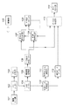
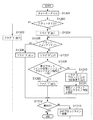
図1は、実施形態における画像符号化装置のブロック構成図である。
[First Embodiment]
FIG. 1 is a block configuration diagram of an image encoding device according to the embodiment.
本実施形態の画像符号化装置の縮小画像生成手段が、装置外部からの入力画像データ中の着目N画素(Nは2以上の整数)に対応する1画素を出力することで縮小画像データを生成する。すなわち、入力画像データの総画素数をMとしたとき、縮小画像生成手段は、着目N画素に対応する1画素を出力する処理をM/N回繰り返すことで、M/N画素数の縮小画像を生成する。そして、解像度補間情報生成手段が、元解像度の画像を復元するための着目N画素の補間方法を複数種類の補間手法から特定する、解像度補間情報を生成する。そして、この解像度補間データと、縮小画像データの符号化データからなる符号列を生成し、出力するものである。ここで、解像度補間情報生成手段が生成する解像度補間情報で示される補間方法の種類は、着目N画素を、当該着目N画素に対応する縮小画像中の1画素、又は、当該縮小画像中の1画素の周囲に位置する少なくとも1画素から復元する第1の補間方法と、着目N画素を、着目N画素の少なくとも一部を、縮小画像を参照せずに復元する第2の補間方法が含まれることを特徴とするものである。 The reduced image generation means of the image encoding apparatus according to the present embodiment generates reduced image data by outputting one pixel corresponding to N pixels of interest (N is an integer of 2 or more) in the input image data from the outside of the apparatus. To do. That is, when the total number of pixels of the input image data is M, the reduced image generation unit repeats the process of outputting one pixel corresponding to the N pixel of interest M / N times, thereby reducing the reduced image having the number of M / N pixels. Is generated. Then, the resolution interpolation information generation unit generates resolution interpolation information that specifies an interpolation method of the N pixel of interest for restoring the original resolution image from a plurality of types of interpolation methods. A code string including the resolution interpolation data and the encoded data of the reduced image data is generated and output. Here, the type of the interpolation method indicated by the resolution interpolation information generated by the resolution interpolation information generating means is the target N pixel, one pixel in the reduced image corresponding to the N pixel of interest, or 1 in the reduced image. A first interpolation method for restoring from at least one pixel located around the pixel, and a second interpolation method for restoring the N pixel of interest at least a part of the N pixel of interest without referring to the reduced image. It is characterized by this.
なお、入力画像データの入力源は、イメージスキャナとするが、画像データをファイルとして格納している記憶媒体等であっても良いし、印刷データ等の情報に基づいてレンダリングするレンダリング部であっても良く、その種類は問わない。また、実施形態では、上記の「N」で表わされる画素数が2×2個(=4画素)とする例を説明する。 The input source of the input image data is an image scanner, but it may be a storage medium storing image data as a file, or a rendering unit that renders based on information such as print data. No matter what type. In the embodiment, an example in which the number of pixels represented by the above “N” is 2 × 2 (= 4 pixels) will be described.
本実施形態に係る画像符号化装置の符号化対象とする画像データは、RGBカラー画像データであり、各コンポーネント(色成分)は8ビットで0〜255の範囲の輝度値を表現した画素データにより構成されるものとする。符号化対象の画像データの並びは点順次、即ち、ラスタースキャン順に各画素を並べ、その各画素はR,G,Bの順番でデータを並べて構成されるものとする。画像は水平方向W画素、垂直方向H画素により構成されるものとする。説明簡易化のため、W、Hは後述する符号化の処理単位、タイルのサイズ(本実施形態では水平、垂直方向とも32画素)の整数倍であるとして説明する。但し、入力画像データはRGB以外の色空間、例えば、YCbCrやCMYKでも構わず、その色空間の種類、成分の数は問わない。さらに、1成分のビット数も8ビットに限らず、8ビットを超えるビット数でも構わない。 The image data to be encoded by the image encoding device according to the present embodiment is RGB color image data, and each component (color component) is represented by pixel data representing a luminance value in the range of 0 to 255 in 8 bits. Shall be composed. Assume that the image data to be encoded is arranged in the order of dots, that is, in the raster scan order, and the pixels are arranged in the order of R, G, and B. The image is assumed to be composed of horizontal W pixels and vertical H pixels. For simplification of explanation, W and H are assumed to be integer multiples of an encoding processing unit and tile size (32 pixels in the present embodiment both in the horizontal and vertical directions) described later. However, the input image data may be a color space other than RGB, for example, YCbCr or CMYK, and the type of the color space and the number of components are not limited. Further, the number of bits of one component is not limited to 8 bits, and the number of bits exceeding 8 bits may be used.
以下、図1に示す画像符号化装置における符号化処理を説明する。図中、115は図1の画像符号化装置全体の動作を制御する制御部である。各処理部は制御部115の制御によって協調して動作する。
Hereinafter, the encoding process in the image encoding apparatus shown in FIG. 1 will be described. In the figure,
まず、画像入力部101は符号化対象となる画像データを順に入力し、ラインバッファ102に出力する。画像データの入力順序は先に説明したとおりラスタースキャン順とする。
First, the
ラインバッファ102は画像データを所定のライン数(Th)分格納する領域を持ち、画像入力部101から入力される画像データを順次格納していく。ここで、Thは後述するタイル分割部103で切り出される矩形ブロック(タイル)の垂直方向の画素数であり、本実施形態では“32”である。以降、符号化対象画像データをThラインの幅で分割したデータをストライプと呼ぶ。ラインバッファ102に必要とされる容量、即ち1ストライプのデータ量はW×Th×3(RGB分)バイトである。先に述べた通り、説明の便宜上、垂直方向画素数HはThの整数倍であるとし、画像の末尾で不完全なストライプが発生しないものとする。
The
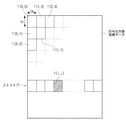
さて、ラインバッファ102に1ストライプの画像データ、即ち、Thライン分の画像データが格納されると、タイル分割部103はラインバッファ102に格納されるThライン分の画像データから、水平方向Tw画素、垂直方向Th画素で構成される矩形ブロックに分割して、ブロック単位に読み出してタイルバッファ104へと格納する。先に説明したように、符号化対象の画像の水平方向画素数WはTwの整数倍としているので、矩形ブロックに分割した場合に不完全なブロックが発生しないものとする。また、この水平方向Tw画素、垂直方向Th画素で構成される矩形ブロックをこれ以降「タイル」と呼ぶ。なお、実施形態では、Tw=Th=32としているので、1タイルのサイズは32×32画素となる。
When one line of image data, that is, image data for Th lines is stored in the
図8に符号化対象の画像データとストライプ、タイルの関係を図示する。図のように画像中、水平方向i番目、垂直方向j番目のタイルをT(i,j)と記す。 FIG. 8 illustrates the relationship between image data to be encoded, stripes, and tiles. As shown in the figure, the i-th tile in the horizontal direction and the j-th tile in the vertical direction are denoted as T (i, j).
タイルバッファ104は1タイル分の画素データを格納する領域を持ち、ブロック分割部103から出力されるタイルデータを順次格納していく。タイルバッファ104に必要とされる容量はTw×Th×3(RGB分)バイトである。
The
解像度変換部105は、タイルバッファ104に格納されるタイルデータについて2×2画素の領域から1画素を抽出するサブサンプリングを行い、1/2縮小タイルを生成する。ここで1/2縮小タイルとはタイルバッファ104に格納されるタイルデータを、水平、垂直両方向の画素数を1/2としたタイルを表す。また、2×2画素の領域の画像データを、これ以降、単に画素ブロックと呼ぶ。
The
図3にタイルデータと2×2画素の画素ブロックBnの関係を図示する。また、注目する画素ブロックBnの中の4つの画素を、同図のように、Bn(0,0)、Bn(0,1)、Bn(1,0)、Bn(1,1)と表す。また、注目ブロックBnの前(左隣)の画素ブロックをBn-1、Bnの次(右隣)の画素ブロックをBn+1と表現し、Bnの下のブロックをBn+bと表す。ここで“b”はタイル内の水平方向のブロック数であり、タイルの水平方向画素数Twを用いて表せば、b=Tw/2である。実施形態では、Tw=32であるので、b=16となる。 FIG. 3 illustrates the relationship between tile data and a 2 × 2 pixel block B n . Further, four pixels in the pixel block B n of interest are divided into B n (0, 0), B n (0, 1), B n (1, 0), B n (1 , 1). Further, the block of interest B n before the pixel block of the next (right) pixel blocks B n-1, Bn of (left neighboring) is expressed as B n + 1, B blocks under Bn n + b It expresses. Here, “b” is the number of horizontal blocks in the tile, and b = Tw / 2 when expressed using the number of horizontal pixels Tw of the tile. In the embodiment, since Tw = 32, b = 16.
本実施形態の解像度変換部105は、着目画素ブロックBnのうち、左上隅の位置の画素Bn(0,0)を、1/2縮小タイルの1画素として抽出する。タイルデータ中の全ての画素ブロックB0〜Bm(m= Tw/2 × Th/2−1=16×16−1=255)についてサブサンプリングを行い、オリジナルタイルに対し、水平、垂直方向とも1/2の画素数の1/2縮小タイルを生成する。解像度変換部105は、生成した1/2縮小タイルデータを1/2縮小タイルバッファ106へ格納する。従って、実施形態の場合、W×H画素で構成されるオリジナルの画像データのから、W×H/4画素数の縮小画像を生成する縮小画像生成手段として機能することになる。
補間データ生成部110は、1/2縮小タイルから元のタイルデータを復元するために必要な情報を生成する。即ち、画素ブロック内のサブサンプリング対象となった画素Bn(0,0)を除く、非サンプリング対象の3画素{Bn(0,1),Bn(1,0),Bn(1,1)}を、どのように補間すればよいかを示す補間データを生成するものである。
The interpolation
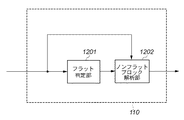
図12は、本実施形態に係る補間データ生成部110の内部のブロック構成図を示す。補間データ生成部110は、フラット判定部1201、ノンフラットブロック解析部1202で構成される。
FIG. 12 is a block diagram showing the internal configuration of the interpolation
フラット判定部1201は、タイル内の画像データが、縮小タイルデータの画素から単純拡大(画素繰り返し)処理して復元可能であるかどうかを判定する“フラット判定”を行う。フラット判定の最小単位は2×2画素の画素ブロックである。以下、この画素ブロックが単純拡大で再現できるブロックである場合、それをフラットブロックと呼び、そうでないブロックをノンフラットブロックと呼ぶこととする。図3において、着目画素ブロックBnがフラットブロックであるのは、以下の式(1)が成り立つ場合である。
Bn(0,0)=Bn(0,1)=Bn(1,0)=Bn(1,1) …(1)
The
B n (0,0) = B n (0,1) = B n (1,0) = B n (1,1) ... (1)
フラット判定部1201の役割は、タイルを構成する各画素ブロックについてフラットブロックかノンフラットブロックかを表す情報を生成する。以下、図13のフローチャートに従い、フラット判定部1201の処理手順を説明する。なお、図13は、1つのタイルに対する処理である点に注意されたい。
The role of the
また、タイルに含まれる全ての画素ブロックがフラットブロックである場合、そのタイルをフラットタイルと呼び、そうでない場合には、ノンフラットタイルと呼ぶ。同様に、タイル内で水平方向に連続するTw/2個(実施形態では16個)のブロック群を以降、ブロックラインと呼ぶ。そして、ブロックライン内の全ブロックがフラットブロックであるとき、そのブロックラインをフラットブロックラインと呼び、少なくとも1つのノンフラットブロックが含まれる場合にはノンフラットブロックラインと呼ぶ。 In addition, when all the pixel blocks included in the tile are flat blocks, the tile is called a flat tile. Otherwise, the tile is called a non-flat tile. Similarly, a group of Tw / 2 blocks (16 blocks in the embodiment) continuous in the horizontal direction in the tile is hereinafter referred to as a block line. When all the blocks in the block line are flat blocks, the block line is called a flat block line, and when at least one non-flat block is included, it is called a non-flat block line.
まず、フラット判定部1201はTw×Th画素のタイルデータを入力する(ステップS1301)。各タイルは独立に処理を行うものとし、タイルの外部の画素(周囲画素)を参照する場合には、各色成分の値が255であるものとして処理する。
First, the
フラット判定部1201は、次に、ステップS1302にて、フラット/ノンフラットの判定を、Tw×Th画素のタイルを構成する2×2画素の画素ブロックが全てに対して行なう。すなわち、着目タイルがフラットタイルであるか否かを判定する。着目タイルがフラットタイルであると判定した場合、処理をステップS1303へ移し、1ビットのフラグ“1”をノンフラットブロック解析部1202に出力し、本処理を終える。
Next, in step S1302, the
一方、着目タイル内に少なくとも1つのノンフラットブロックが存在する場合(ステップS1302がNO)には、フラット判定部1201は、処理をステップS1304へ移し、1ビットのフラグ“0”をノンフラットブロック解析部1202に出力し、ステップS1305へ処理を移す。
On the other hand, if there is at least one non-flat block in the tile of interest (step S1302 is NO), the
ステップS1305では、水平方向に連続するb(=Tw/2=16)個の画素ブロックからなるブロックラインのひとつに着目し、ステップS1302と同様に、フラットブロックラインかノンフラットブロックラインかの判定を行う。フラットブロックラインである場合(YES)は、ステップS1306へ処理を移し、1ビットのフラグ“1”をノンフラットブロック解析部1202に出力する。一方、着目ブロックラインがノンフラットブロックラインであると判定した場合(ステップS1305がNO)には、処理をステップS1307へ移し、1ビットのフラグ”0”をノンフラットブロック解析部1202に出力して、処理をステップS1308へ移す。
In step S1305, attention is paid to one of the block lines composed of b (= Tw / 2 = 16) pixel blocks continuous in the horizontal direction, and whether the block block line is a flat block line or a non-flat block line is determined as in step S1302. Do. If it is a flat block line (YES), the process moves to step S1306, and a 1-bit flag “1” is output to the non-flat
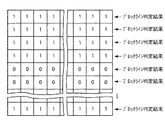
ステップS1308に至る場合には、着目するブロックライン内に、少なくとも1つのノンフラットブロックが存在することになる。このため、着目するブロックラインを構成するb(=Tw/2=16)個のブロックそれぞれについて、フラット/ノンフラットブロックの判定結果を示すフラグの配列が必要となる。ここで、ブロックのフラグは1ビットでよく、フラットブロックの場合は“1”、ノンフラットブロックの場合は“0”とする。実施形態の場合、ブロックラインはb(=16)個の画素ブロックで構成されるので、ノンフラットブロックラインのフラグ配列はb個、すなわち、16ビットとなる。 When the process reaches step S1308, at least one non-flat block exists in the block line of interest. For this reason, for each of b (= Tw / 2 = 16) blocks constituting the target block line, an array of flags indicating flat / non-flat block determination results is required. Here, the block flag may be 1 bit, and is “1” for a flat block and “0” for a non-flat block. In the case of the embodiment, since the block line is composed of b (= 16) pixel blocks, the flag arrangement of the non-flat block line is b, that is, 16 bits.
ステップS1308では、着目するブロックラインのフラグ配列を以前のノンフラットブロックラインのフラグ配列と比較し、一致するか否かを判定する。なお、着目ブロックラインが着目タイルの最初のブロックラインである場合には、それ以前のブロックラインは存在しない。そこで、フラット判定部1201は、着目タイルのブロックラインの判定に先立ち、内部のメモリに、ブロックラインの全ブロックがノンフラットブロックであることを示す情報を予め用意しておく。つまり、フラットブロックを“1”、ノンフラットブロックを“0”と定義したとき、初期値としてb個(bビット)の“0”を用意しておく。以降、このbビットを“参照ノンフラットブロックライン情報”と呼ぶ。勿論、復号装置でも1タイルの復元する際には、“参照ノンフラットブロックライン情報”を用意しておく。
In step S1308, the flag array of the target block line is compared with the flag array of the previous non-flat block line to determine whether or not they match. If the target block line is the first block line of the target tile, there is no previous block line. Therefore, the
従って、ステップS1308では、着目ブロック内の各ブロックのフラットブロック/ノンフラットブロックの判定結果の並びが、参照ノンフラットブロックライン情報と一致するか否かを判定することになる。 Accordingly, in step S1308, it is determined whether or not the arrangement of the determination results of the flat block / non-flat block of each block in the block of interest matches the reference non-flat block line information.
ここで、図10のタイルデータを例にして、ステップS1308の判定処理を説明する。このタイルデータはは、先頭から4番目までのブロックラインがフラットブロックラインであり、5番目のブロックラインがノンフラットブロックラインの例である。図10のタイルに対する画素ブロックのフラット/ノンフラットの判定結果は、図11に示す通りとなる。 Here, the determination processing in step S1308 will be described using the tile data in FIG. 10 as an example. The tile data is an example in which the fourth block line from the top is a flat block line and the fifth block line is a non-flat block line. The pixel block flat / non-flat determination result for the tile of FIG. 10 is as shown in FIG.
今、5番目のブロックラインが着目ブロックラインであるとする。着目ブロックラインは5番目のブロックラインであるから、そのブロックラインは着目タイル内の最初のノンフラットブロックラインであると判定される。従って、その着目ブロックラインに含まれる画素ブロックの判定結果と、参照ノンフラットブロックライン情報(16ビットの“000…000”)と比較され、一致すると判定される。 Assume that the fifth block line is the target block line. Since the target block line is the fifth block line, it is determined that the block line is the first non-flat block line in the target tile. Accordingly, the determination result of the pixel block included in the target block line is compared with the reference non-flat block line information (16 bits “000... 000”), and it is determined that they match.
このように、着目ブロックラインの判定結果と参照ノンフラットブロックライン情報とが一致したと判定した場合には、ステップS1309にて、着目ブロックライン内の各ブロックの判定結果が、参照ノンフラットブロックライン情報と一致したことを示す1ビットのフラグ“1”をノンフラットブロック解析部1202に出力する。この場合、ブロック毎のフラット/ノンフラット判定結果を示すb(=Tw/2)bitのフラグは出力しなくてよい。
As described above, when it is determined that the determination result of the target block line matches the reference non-flat block line information, in step S1309, the determination result of each block in the target block line is the reference non-flat block line. A 1-bit flag “1” indicating that it matches the information is output to the non-flat
一方、着目ブロックラインのフラット/ノンフラット判定結果を示すフラグの配列が、参照ノンノンフラットブロックラインと一致しない場合(ステップS1308がNO)は、ステップS1310へ処理を移す。ここでは、フラット判定部1201は先ず、1ビットのフラグ”0”をノンフラットブロック解析部1202に出力する。そして、それに後続して着目ブロックラインのフラット/ノンフラット判定結果を示すフラグ配列(Tw/2ビット)をノンフラットブロック解析部1202に出力する。この後、フラット判定部1201は、ステップS1311にて、着目ブロックラインのフラットブロック/ノンフラットブロックの判定結果(bビット)で、参照ノンフラットブロックライン情報を更新する。
On the other hand, when the arrangement of flags indicating the flat / non-flat determination result of the target block line does not match the reference non-non-flat block line (NO in step S1308), the process proceeds to step S1310. Here, the
注目しているブロックラインに対して、フラット/ノンフラット判定が終了したら、ステップS1312へ処理を移し、注目ブロックラインが、着目タイル内の最終ブロックラインであるか否かの判定を行う。最終ブロックラインではない場合(NO)は、着目するブロックラインを次のブロックラインへ移す(ステップS1313)。そして、ステップS1305へ処理を戻して同様の処理を繰り返す。最終ブロックラインであった場合(YES)は、タイルデータに対するフラット判定処理を終了する。 When the flat / non-flat determination for the target block line is completed, the process proceeds to step S1312, and it is determined whether the target block line is the last block line in the target tile. If it is not the last block line (NO), the target block line is moved to the next block line (step S1313). Then, the process returns to step S1305 to repeat the same process. If it is the last block line (YES), the flat determination process for the tile data is terminated.
フラット判定部1201は、以上の処理を、着目するタイルデータについて行い、フラット/ノンフラットの判定結果をノンフラットブロック解析部1202へ出力する。
The
次に、ノンフラットブロック解析部1202の処理を説明する。
Next, processing of the non-flat
このノンフラットブロック解析部1202は、フラット判定部1201と同様に、1タイルに相当する処理の開始時に、1ブロックラインの全ブロックがノンフラットブロックを示す「参照ノンフラットブロックライン情報」を設定しておく。そして、ノンフラットブロック解析部1202は、フラット判定部1201からの判定結果を解析しつつ、そのまま通過させ、補間データバッファ112に出力する。このとき、ノンフラットブロック解析部1202は、先の図13のステップS1310にて、1ビットのフラグ“0”が出力されたブロックラインが存在すると判定した場合、それに後続する各ブロックのフラットブロック/ノンフラットブロックを示す判定結果で、参照ノンフラットブロックライン情報を更新する。もし、着目ブロックラインに対し図13のステップS1309の処理が行われた場合には、その際の参照ノンフラットブロックラインを参照することで、どのブロックがノンフラットブロックであるのかを判定できる。また、着目ブロックラインに対し、図13のステップS1310の処理が行われていると判断した場合には先頭の1ビットのフラグ“0”に後続するbビットの値を調べれば、ブロックがノンフラットブロックであるのかを判定できる。すなわち、ノンフラットブロック解析部1202は、着目タイル中の全てのノンフラットブロックの位置と個数を判定できることになる。そして、ノンフラットブロック解析部1202は、縮小タイルの画素の単純拡大では再現できない2×2画素で構成される画素ブロック(ノンフラットブロック)に対して、その画素ブロック内の色数や配置を解析して、付加情報を生成し、出力する。すなわち、ノンフラットブロック解析部1202は、フラット判定部1201から出力される、フラット/ノンフラットの判定結果を受け取り、ノンフラットブロックについて、解析を行い、ノンフラットブロックを復元するための情報を生成し、出力する。
This non-flat
ノンフラットブロック解析部1202は、ノンフラットブロックと判定されたブロックにつき、図15のフローチャートに従ったノンフラットブロック符号化処理を行なう。以下、同図に従って、ノンフラットブロック解析部1202の処理を説明する。
The non-flat
先ず、ステップS1501にて、1個のノンフラットブロックBnを着目ブロックとし、2×2画素の画素ブロックデータを入力する。そして、ステップS1502にて、着目画素ブロックBnが、以下の式(2)が成立するブロックであるかどうかの判定を行う。
Bn(0,1)=Bn+1(0,0)
且つ
Bn(1,0)=Bn+b(0,0)
且つ
Bn(0,1)=Bn+b+1(0,0) …(2)
First, in step S1501, 2 × 2 pixel block data is input with one non-flat block B n as a target block. In step S1502, it is determined whether the target pixel block B n is a block that satisfies the following expression (2).
B n (0,1) = B n + 1 (0,0)
And B n (1, 0) = B n + b (0, 0)
And B n (0,1) = B n + b + 1 (0,0) (2)
上記式(2)が成り立つブロックBnを、以降、周囲3画素一致ブロックと定義する。上記式(2)に示すように、ペア{Bn(0,1)、Bn+1(0,0)}、{Bn(1,0)、Bn+b(0,0)}、及び、{Bn(0,1)とBn+b+1(0,0)}との一致/不一致を判定するのには、理由がある。 Hereinafter, the block B n in which the above expression (2) is satisfied is defined as a peripheral three-pixel matching block. As shown in the equation (2), pairs {Bn (0,1), B n + 1 (0,0)}, {B n (1,0), B n + b (0,0)}, And there is a reason for determining the match / mismatch between {B n (0,1) and B n + b + 1 (0,0)}.
一般に、着目画素と、その着目画素に隣接する画素間の相関度は高いし、そのような画像が多い。そのため、着目画素の画素値を予測する場合には、その隣接する画素を予測のための参照画素として使用することが多い。着目ブロック内の4画素が全て同一ではない、すなわち、フラットブロックではないという条件下では、ペア{Bn(0,1)、Bn+1(0,0)}、{Bn(1,0)、Bn+b(0,0)}、及び、{Bn(0,1)とBn+b+1(0,0)}とが一致する可能性が高いことを実験により得られた。 In general, the degree of correlation between a pixel of interest and a pixel adjacent to the pixel of interest is high, and there are many such images. Therefore, when predicting the pixel value of the pixel of interest, the adjacent pixel is often used as a reference pixel for prediction. Under the condition that all four pixels in the target block are not the same, that is, they are not flat blocks, the pair {Bn (0,1), Bn + 1 (0,0)}, { Bn (1,0) ), B n + b (0,0)} and {B n (0,1) and B n + b + 1 (0,0)} are highly likely to match by experiment. It was.
この理由で、Bn(0,1)とBn+1(0,0)とが一致するか否かを判定するようにした。他のペア{Bn(1,0)、Bn+W(0,0)}、及び、{Bn(0,1)とBn+W+1(0,0)}を比較するのも同じ理由である。そして、先に示した式(2)が満たされる場合(3つのペアが互いに等しい場合)、短い符号語を割り当てることで情報量の削減できた。 For this reason, B n and (0, 1) B n + 1 and (0,0) is adapted to determine whether the match. Compare the other pairs {B n (1,0), B n + W (0,0)} and {B n (0,1) and B n + W + 1 (0,0)} Is the same reason. When the above-described equation (2) is satisfied (when the three pairs are equal to each other), the amount of information can be reduced by assigning a short codeword.
なお、実施形態では、各画素ブロックの左上隅の位置の画素をサブサンプリングして縮小画像を生成した。従って、式(2)における、画素Bn+1(0,0)、Bn+b(0,0)、Bn+b+1(0,0)は、着目画素ブロックBnに隣接する画素ブロック内のサブサンプリング対象画素でもある点に注意されたい。 In the embodiment, the reduced image is generated by sub-sampling the pixel at the upper left corner of each pixel block. Accordingly, the pixels B n + 1 (0,0), B n + b (0,0), and B n + b + 1 (0,0) in the expression (2) are pixels adjacent to the pixel block Bn of interest. Note that it is also a sub-sampling target pixel in the block.
さて、注目ブロックBnが、式(2)の成立するブロックである場合には、Bn(0,1)、Bn(1,0)、Bn(1,1)の位置の3画素が、周囲の画素から再現可能であると判断できる。但し、ブロックが画像の右端もしくは、画像の下端に位置する場合には、ブロックの外側の画素を参照することができない。そのため、外側の画素の各成分を仮想的に、予め任意の値を設定しておき、その画素値との一致/不一致判定を行うこととする。本実施形態では、仮想的に、各成分値を“255”を設定しておく。しかし、“255”に限らず、符号化側と復号側で同じ値を用いるように定めておけばこれ以外の値でも構わない。 Now, if the target block Bn is a block for which the expression (2) is established, the three pixels at the positions Bn (0,1), Bn (1,0), Bn (1,1) It can be determined that the pixel can be reproduced. However, when the block is located at the right end of the image or the lower end of the image, the pixels outside the block cannot be referred to. For this reason, an arbitrary value is set in advance for each component of the outer pixel, and matching / mismatching with the pixel value is determined. In the present embodiment, “255” is set for each component value virtually. However, the value is not limited to “255”, and other values may be used as long as the same value is used on the encoding side and the decoding side.
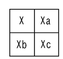
図4に、注目する2×2画素の画素ブロックを示す。図4に示す画素Xが縮小画像生成のためにサブサンプリングされた画素を示し、着目画素ブロックBn内の画素Bn(0,0)に相当するものである。また、画素Xa,Xb,Xcは着目ブロックBn内の画素(0,1),Bn(1,0),Bn(1,1)の画素を示している。以下、画素X、Xb,Xc,Xdを用いて説明する。 FIG. 4 shows a 2 × 2 pixel block of interest. It indicates a pixel which is sub-sampled for pixel X is reduced image generation shown in FIG. 4, which corresponds to a pixel B n in the target pixel block Bn (0,0). The pixel Xa, Xb, Xc indicates the pixels of the pixel in the target block B n (0,1), B n (1,0), B n (1,1). Hereinafter, description will be made using the pixels X, Xb, Xc, and Xd.
さて、ステップS1502にて、式(2)の成立すると判定した場合、着目ブロックBn内の画素Xa、Xb、Xcは、縮小画像の画素からそのまま再現できることになる。従って、ステップS1503へ処理を移し、再現できることを示す1ビットのフラグ“1”を出力する。一方、着目ブロックが式(2)を満足しないブロックあると判定された場合、ステップS1504へ処理を移し、1ビットのフラグ“0”を出力する。 If it is determined in step S1502 that Expression (2) is established, the pixels Xa, Xb, and Xc in the block of interest Bn can be reproduced as they are from the pixels of the reduced image. Accordingly, the process moves to step S1503, and a 1-bit flag “1” indicating that the data can be reproduced is output. On the other hand, if it is determined that the target block is a block that does not satisfy Expression (2), the process proceeds to step S1504, and a 1-bit flag “0” is output.
次に、処理はステップS1505に進み、着目ブロックに含まれる色数が“2”か、それ以上(3、もしくは4色)かを判定する。なお、着目ブロックはノンフラットブロックであるので、色数が“1”となることは有り得ない。 Next, the process proceeds to step S1505, and it is determined whether the number of colors included in the block of interest is “2” or more (3 or 4 colors). Since the block of interest is a non-flat block, the number of colors cannot be “1”.
着目ブロックに含まれる色数が“2”より大きい(3、もしくは4色)と判定した場合、ステップS1512にて、1ビットのフラグ“0”を出力する。そして、ステップS1513にて、縮小画像として非使用の3画素Xa,Xb,Xcの画素データを出力する。実施形態では、1画素がR、G、Bの3コンポーネントであり、1コンポーネントが8ビットとしているので、3画素Xa,Xb,Xcの合計ビット数は3×8×3=72ビットとなる。 If it is determined that the number of colors included in the block of interest is greater than “2” (3 or 4 colors), a 1-bit flag “0” is output in step S1512. In step S1513, pixel data of three unused pixels Xa, Xb, and Xc are output as a reduced image. In the embodiment, since one pixel has three components of R, G, and B, and one component has 8 bits, the total number of bits of the three pixels Xa, Xb, and Xc is 3 × 8 × 3 = 72 bits.
一方、着目ブロックに含まれる色数が“2”であると判定した場合、ステップS1506にて出現色数が“2”であることを示す1ビットのフラグ“1”を出力する。そして、ステップS1507にて、着目ブロック内の、縮小画像に利用されている図4の画素Xを除く3画素Xa,Xb,Xcが、図16のパターン1601乃至1607のいずれであるのかを示す画素配置情報を出力する。図16に示すようにパターン数は全部で7つあるので、画素配置情報は3ビットであれば1つのパターンを特定できる。ただし、実施形態では、縮小画像に利用されている画素と同じ色の画素は“1”、異なる色の画素を“0”と表わし、図4の画素Xa,Xb,Xcに相当する各ビットをその順番に出力するようにした(この場合も3ビットとなる)。例えば、図16のパターン1601に一致する場合、画素Xa,Xb,Xcは同色であり、且つ、縮小画像に利用されている画素Xの色とは異なるので、画素配置情報の3ビットは“000”となる。また、パターン1602の場合は、“100”、パターン1603の場合には“010”、パターン1604の場合には“001”となる。他は説明するまでもないであろう。
On the other hand, if it is determined that the number of colors included in the block of interest is “2”, a 1-bit flag “1” indicating that the number of appearance colors is “2” is output in step S1506. In step S1507, the pixels indicating which of the
次いで、ステップS1508にて、着目ブロックBn内の縮小画像に利用された画素Xを除く画素Xa,Xb,Xcのうち、画素Xと異なる色の画素と同じ色の画素が、近傍に存在するか否かを判断する。本実施形態では、比較する近傍の画素は、着目ブロックの右隣のブロックBn+1の画素Bn(0,0)、着目ブロックの直下のブロックBn+bの画素Bn+b(0,0)、着目ブロックの右下に隣接するブロックBn+b+1の画素Bn+b+1(0,0)とし、この順番に比較する。3画素のいずれかと一致するかを示せば良いので、この比較結果は2ビットとした。そして、一致するのが、Bn+1(0,0)であった場合には2ビットの“11”、Bn+b(0,0)と一致するなら2ビットの“01”、Bn+b+1(0,0)とが一致するなら2ビットの“10”を出力する(ステップS1509)。また、周辺の3画素のいずれとも一致しない場合(NO)には、処理をステップS1510へ移し、2ビットのフラグ“00”を出力する。そして、第2色の画素値を出力し(ステップS1511)、注目ブロックBnに対する処理を終了する。本実施形態では符号化対象画像が、各色8ビットのRGBデータであるからステップS1511においては24ビットが出力される。 Next, in step S1508, among the pixels Xa, Xb, and Xc excluding the pixel X used in the reduced image in the block of interest Bn , a pixel having the same color as the pixel having a color different from the pixel X exists in the vicinity. Determine whether or not. In this embodiment, the neighboring pixels to be compared are the pixel B n (0, 0) of the block B n + 1 right next to the block of interest, and the pixel B n + b (block B n + b of the block B n + b immediately below the block of interest). 0,0) and the pixel B n + b + 1 (0,0) of the block B n + b + 1 adjacent to the lower right of the target block, and are compared in this order. Since it only has to indicate which of the three pixels matches, this comparison result is 2 bits. If B n + 1 (0, 0) matches, 2 bits “11”, and if B n + b (0, 0) matches, 2 bits “01”, B If n + b + 1 (0, 0) matches, 2-bit “10” is output (step S1509). If none of the three neighboring pixels match (NO), the process proceeds to step S1510, and a 2-bit flag “00” is output. Then, the pixel value of the second color is output (step S1511), and the process for the block of interest Bn ends. In this embodiment, since the encoding target image is RGB data of 8 bits for each color, 24 bits are output in step S1511.
こうして、注目ブロックBnの処理が終了したら、ステップS1514により、着目ブロックが着目タイル中の最後のノンフラットブロックであるか否かの判定を行う。否の場合には、次のノンフラットブロックの処理に移る(ステップS1515)。次のノンフラットブロックに対しても、ステップS1501からの処理を同様に行う。また、着目ブロックが最後のノンフラットブロックであると判定した場合には、本処理を終了する。 Thus, When the processing of the target block B n is completed, in step S1514, it is determined whether the target block is the last non-flat blocks in the tile of interest. If not, the process proceeds to the next non-flat block processing (step S1515). The processing from step S1501 is similarly performed for the next non-flat block. If it is determined that the block of interest is the last non-flat block, this process is terminated.
上記のようにして、ノンフラットブロック解析部1202からは、フラット/ノンフラット判定結果と、ノンフラットブロックの解析結果により生成された補間データが出力される。これらのデータは補間データバッファ112に格納される。
As described above, the non-flat
なお、2×2画素で表わされる画素ブロックは、これまでの説明からわかるように、以下の(a)乃至(e)の5種類に分類できる。
(a)フラットブロック
(b)ノンフラットブロック、かつ、周囲3画素一致ブロック
(c)ノンフラットブロック、かつ、そのブロック内に出現する色数が“2”であり、周辺画素に第2色と同じ色の画素が存在するブロック、
(d)ノンフラットブロック、かつ、そのブロック内に出現する色数が“2”であり、周辺画素に第2色と同じ色の画素が存在しないブロック、
(e)ノンフラットブロック、かつ、そのブロック内に出現する色数が“2”より多い(3色、もしくは4色)ブロック
Note that pixel blocks represented by 2 × 2 pixels can be classified into the following five types (a) to (e) as can be seen from the above description.
(A) a flat block, (b) a non-flat block, and a peripheral three-pixel matching block (c) a non-flat block, and the number of colors appearing in the block is “2”, A block with pixels of the same color,
(D) a non-flat block and a block in which the number of colors appearing in the block is “2” and a pixel having the same color as the second color does not exist in the peripheral pixels;
(E) A non-flat block and a block in which the number of colors appearing in the block is greater than “2” (3 colors or 4 colors)
補間データ生成部110は、上記の処理を行なっている最中に、画素ブロックが上記(a)乃至(e)のいずれに該当するかを判定し、それぞれのブロックの出現数を計数する。以降、上記種類(a)乃至(e)のブロック数をNa、Nb、Nc,Nd、Neと表わす。
While performing the above processing, the interpolation
補間データ生成部110は、1タイルに対して補間データを生成するに先立って、Na乃至Neを“0”で初期化し、1タイルに対する補間データの生成及び出力が完了したとき、計数したブロック数Na乃至Neを符号化方式選択部111に出力する。
The interpolation
実施形態では、1タイルが32×32画素で構成されるので、その中には16×16個の画素ブロックが存在することになる。従って、補間データ生成部110が、仮に図13のステップS1303の処理を行なった場合、注目タイル内の全画素ブロックは、フラットブロックであることになり、Na=256となり、Na以外のブロック数Nb乃至Neは“0”として決定できる。また、ステップS1306の処理を行なった場合には、それまでに計数したNaに“16”を加算すればよい。そして、図15のステップS1503の処理を行なった場合には、Naに“1”を加算する。また、ステップS1512の処理を行なった場合にはNeに“1”を加算する。それ以外については、これまでの説明から十分に理解できよう。
In the embodiment, since one tile is composed of 32 × 32 pixels, 16 × 16 pixel blocks exist in the tile. Therefore, if the interpolation
さて、符号化方式選択部111は、補間データ生成部110が計数したブロック数Na乃至Neの頻度分布に基づき、1/2縮小タイルバッファ106に格納される1/2縮小タイルデータの符号化方法を決定し、その決定結果を2値(1ビット)の制御信号として非可逆符号化部107、可逆符号化部108、及び、符号列形成部113に出力する。この結果、非可逆符号化部107、可逆符号化部108のいずれか一方が、1/2縮小タイルバッファ106に格納された1/2縮小タイルデータの符号化処理を行なう。そして、生成された符号化データが符号列形成部113に出力される。実施形態では、符号化方式選択部111からの制御信号が“0”のとき非可逆符号化部107が非可逆符号化処理を行ない、“1”の場合に可逆符号化部108が可逆符号化処理を行なうものとする。
The encoding
一般に、文字、線画、クリップアート画像などでは、先に示したブロックの種類(a)乃至(c)が多い傾向が見られる。換言すれば、文字、線画、クリップアート画像などの場合、ブロック数Na乃至Ncの値が大きくなる。一方、複雑なCG画像や自然画像などでは、ブロック数Nd、Neの値が大きくなる傾向が見られる。また、文字、線画、クリップアートなどでは、非可逆符号化による画質劣化が目に付きやすく、可逆符号化により高い圧縮性能を得られる傾向にある。一方、複雑なCGや自然画像では、逆に非可逆符号化による画質劣化が目に付きにくく、かつ、可逆符号化では高い圧縮性能を得られない傾向がある。 In general, characters, line drawings, clip art images, and the like tend to have many types of blocks (a) to (c) described above. In other words, in the case of characters, line drawings, clip art images, etc., the number of blocks Na to Nc increases. On the other hand, in complex CG images and natural images, the number of blocks Nd and Ne tend to increase. In addition, in characters, line drawings, clip arts, and the like, image quality deterioration due to lossy encoding is easily noticeable, and high compression performance tends to be obtained by lossless encoding. On the other hand, with complex CG and natural images, image quality degradation due to lossy encoding is hardly noticeable, and high compression performance tends not to be obtained with lossless encoding.
更には、ブロックの種類(a)乃至(c)の画素ブロックは、縮小画像の画素値を用いて元画像を復元することになる。従って、仮に、縮小画像に画素変化(劣化)が生じた場合、復号時に元の解像度の画像を復元する際にその劣化を広げる方向に作用する。このため、縮小画像符号化時の画質劣化の影響を受け易い。 Furthermore, the pixel blocks of the block types (a) to (c) restore the original image using the pixel values of the reduced image. Therefore, if a pixel change (deterioration) occurs in the reduced image, it acts in the direction of widening the deterioration when restoring the original resolution image during decoding. For this reason, it is easy to be affected by image quality degradation at the time of reduced image encoding.
反対に、ブロックの種類(d),(e)の画素ブロックは、縮小画像に含まれない画素(色)の情報が直接指定されるため、画質劣化の影響が少ない。 On the other hand, in the pixel blocks of the block types (d) and (e), the information on the pixels (colors) not included in the reduced image is directly specified, so that the influence of image quality deterioration is small.
上記の通りなので、符号化方式選択部111は、Na,Nb,Ncの値が大きい場合は、1/2縮小タイルデータについては、可逆符号化を適用するよう、制御信号“1”を出力する。また、符号化方式選択部111は、Nd、Neの値が大きい場合は、1/2縮小タイルについては、非可逆符号化を適用するよう、制御信号“0”を出力する。
As described above, when the values of Na, Nb, and Nc are large, the encoding
具体的には、符号化方式選択部111は、予め設定された閾値TH1と、Na+Nb+Ncの合算値とを比較し、次式(3)を満たすとき、制御信号“1”を出力し、満たさない場合には制御信号“0”を出力する。
Na+Nb+Nc>TH1 …(3)
上記式(3)の代りに、次式(4)を採用しても良い。これら式(3)、(4)は互いに等価のものであるのは理解できよう。
Nd+Ne≦TH1 …(4)
なお、閾値TH1は、ユーザが適宜設定できるようにするものとするが、典型的には、タイルに含まれるブロック数の1/2を示す値が好適である。実施形態では、1タイルには16×16個の画素ブロックが含まれるので、TH1=128となる。
Specifically, the encoding
Na + Nb + Nc> TH1 (3)
Instead of the above formula (3), the following formula (4) may be adopted. It will be understood that these equations (3) and (4) are equivalent to each other.
Nd + Ne ≦ TH1 (4)
Note that the threshold value TH1 can be set as appropriate by the user. Typically, a value indicating 1/2 of the number of blocks included in the tile is suitable. In the embodiment, since one tile includes 16 × 16 pixel blocks, TH1 = 128.
さて、非可逆符号化部107は、符号化方式選択部111から出力される制御信号が“0”である場合に、1/2縮小タイルバッファ106に格納される1/2縮小タイルデータを非可逆符号化方式で符号化して符号化データを生成し、生成した符号化データを符号化データバッファ109に格納する。
The
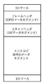
非可逆符号化部107における非可逆符号化処理としては様々な手法が適用可能である。ここでは静止画像符号化の国際標準方式として勧告されているJPEG(ITU−T T.81|ISO/IEC10918−1)のベースライン方式を適用するものとする。JPEGについては勧告書等に詳細な説明があるのでここでは説明を省略する。但し、JPEG符号化で用いるハフマンテーブル、量子化テーブルは全てのタイルで同じものを使用することとし、全タイルで共通となるフレームヘッダや、スキャンヘッダ、各種テーブルなどについては符号化データバッファ109に格納せず、符号化データ部分のみを格納することとする。即ち、図7に示した一般的なJPEGベースライン符号化データの構成のうち、スキャンヘッダの直後からEOIマーカの直前までのエントロピ符号化データセグメントのみが格納される。なお、ここでは説明簡略化のため、DRI、RSTマーカによるリスタートインターバルの定義や、DNLマーカによるライン数の定義などは行わないものとする。
Various methods can be applied as the irreversible encoding process in the
可逆符号化部108は、符号化方式選択部111から出力される制御信号が“1”である場合に、1/2縮小タイルバッファ106に格納される1/2縮小タイルデータを可逆符号化して符号化データを生成する。そして、可逆符号化部108は、生成した符号化データを符号化データバッファ109に格納する。可逆符号化部108が実行する可逆符号化にも様々なものがあるが、ここではその一例として、国際標準方式としてISOとITU−Tから勧告されるJPEG−LS(ITU−T T.87|ISO/IEC14495−1)を用いるものとする。しかしながら、JPEG(ITU−T T.81|ISO/IEC10918−1)のロスレスモードなど、他の可逆符号化手法を用いても構わない。JPEG−LSの詳細についても勧告書等に記載されているので、ここでは説明を省略する。また、JPEGと同様にヘッダ等はバッファに格納せず、符号化データ部分のみを格納することとする。
The
符号列形成部113は、符号化方式選択部111から出力される制御信号と、補間データバッファ112に格納される補間データ、符号化データバッファ109に格納される1/2縮小タイルの符号化データを結合させ、必要な付加情報を加えて本画像符号化装置の出力となる符号列を、オリジナル画像データに対応する符号化画像データとして形成する。このとき、符号列形成部113は、符号化方式選択部111から出力される制御信号に基づき、どのタイルが可逆符号化され、どのタイルが非可逆符号化されているのかを示す情報も付加して、出力する。
The code
図9(a)は本画像符号化装置の出力符号列のデータ構成を示す図である。出力符号列の先頭には、画像を復号するために必要となる情報、例えば、画像の水平方向画素数、垂直方向画素数、コンポーネント数、各コンポーネントのビット数やタイルの幅、高さなどの付加情報がヘッダとして付けられる。また、このヘッダ部分には、画像データそのものについての情報のみでなく、各タイル共通に使用するハフマン符号化テーブルや、量子化テーブルなど符号化に関する情報も含まれる。図9(b)は各タイルの出力符号列の構成を示す図である。各タイルの先頭にはタイルの番号や大きさなど、復号に必要な各種情報を含んだタイルヘッダがあり、その後に、符号化方式選択部111から出力される制御信号が付加される。ここでは説明のためにあえてタイルヘッダとは別に示しているが、タイルヘッダの中に含めても構わないことは言うまでもない。なお、図9(a),(b)には特に示していないが、各タイルの符号列の長さをタイルの先頭や、符号化データの先頭のヘッダ部分に含めるなどして管理することによりタイル単位のランダムアクセスが可能となるようにしても良い。あるいは、符号化データ中に所定の値が発生しないように工夫を加えて特殊なマーカを設定し、各タイルデータの先頭、または末尾にマーカを置くなどしても同様の効果が得られる。
FIG. 9A is a diagram illustrating a data configuration of an output code string of the present image coding apparatus. At the beginning of the output code string, information necessary for decoding the image, such as the number of pixels in the horizontal direction, the number of pixels in the vertical direction, the number of components, the number of bits of each component, the width of the tile, the height, etc. Additional information is attached as a header. The header portion includes not only information about the image data itself, but also information related to encoding such as a Huffman encoding table and a quantization table used in common for each tile. FIG. 9B is a diagram showing the configuration of the output code string of each tile. Each tile has a tile header including various information necessary for decoding, such as the tile number and size, and a control signal output from the encoding
符号出力部114は符号列形成部113により生成された出力符号列を装置外部へと出力する。出力対象が記憶装置であれば、ファイルとして出力することになる。
The
以上のように、本実施形態の画像符号化装置では、複数の画素で構成されるタイル(実施形態では32×32画素のサイズ)を単位に符号化処理を行う。各タイルについて、縮小画像と、縮小画像から元の画像を復元するための補間データを生成し、縮小画像を可逆符号化、または、非可逆符号化により符号化する。補間データの生成は単純、簡易な処理であり、高度な演算処理を要するビットマップ符号化処理(非可逆符号化部107、可逆符号化部108による符号化処理)を縮小画像に限定することにより、画像全体をビットマップ符号化する場合に比べて、簡易・高速に符号化処理を実現できる。縮小画像の符号化には可逆と非可逆符号化のいずれかを選択して適用するが、補間データの構造に基づいて非可逆符号化を適用した場合の画質への影響が大きい場合には可逆符号化を適用するようにしているため、復号時に解像度を元に戻した場合に画質劣化が拡大されることを防ぐことができる。
As described above, in the image encoding device according to the present embodiment, encoding processing is performed in units of tiles (32 × 32 pixel size in the embodiment) including a plurality of pixels. For each tile, a reduced image and interpolation data for restoring the original image from the reduced image are generated, and the reduced image is encoded by lossless encoding or lossy encoding. Generation of interpolation data is simple and simple processing, and by restricting bitmap encoding processing (encoding processing by the
[第1の実施形態の変形例]
上記第1の実施形態と同等の処理を、コンピュータプログラムによって実現する例を第1の実施形態の変形例として以下に説明する。
[Modification of First Embodiment]
An example in which processing equivalent to that in the first embodiment is realized by a computer program will be described below as a modification of the first embodiment.
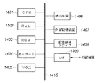
図14は、本変形例における情報処理装置(例えばパーソナルコンピュータ)のブロック構成図である。 FIG. 14 is a block configuration diagram of an information processing apparatus (for example, a personal computer) in the present modification.
図中、1401はCPUで、RAM1402やROM1403に記憶されているプログラムやデータを用いて本装置全体の制御を行うと共に、後述する画像符号化処理、復号処理を実行する。1402はRAMで、外部記憶装置1407や記憶媒体ドライブ1408、若しくはI/F1409を介して外部装置からダウンロードされたプログラムやデータを記憶する為のエリアを備える。また、RAM1402は、CPU1401が各種の処理を実行する際に使用するワークエリアも備える。1403はROMで、ブートプログラムや本装置の設定プログラムやデータを格納する。1404、1405は夫々キーボード、マウスで、CPU1401に対して各種の指示を入力することができる。
In the figure,
1406は表示装置で、CRTや液晶画面などにより構成されており、画像や文字などの情報を表示することができる。1407はハードディスクドライブ装置等の大容量の外部記憶装置である。この外部記憶装置1407には、OS(オペレーティングシステム)や後述する画像符号化、復号処理の為のプログラム、符号化対象の画像データ、復号対象画像の符号化データなどがファイルとして保存されている。また、CPU1401は、これらのプログラムやデータをRAM1402上の所定のエリアにロードし、実行することになる。
A display device 1406 includes a CRT, a liquid crystal screen, and the like, and can display information such as images and characters.
1408は記憶媒体ドライブで、CD−ROMやDVD−ROMなどの記憶媒体に記録されたプログラムやデータを読み出してRAM1402や外部記憶装置1407に出力するものである。なお、この記憶媒体に後述する画像符号化、復号処理の為のプログラム、符号化対象の画像データ、復号対象の画像の符号化データなどを記録しておいても良い。この場合、記憶媒体ドライブ1408は、CPU1401による制御によって、これらのプログラムやデータをRAM1402上の所定のエリアにロードする。
A
1409はI/Fで、このI/F1409によって外部装置を本装置に接続し、本装置と外部装置との間でデータ通信を可能にするものである。例えは符号化対象の画像データや、復号対象の画像の符号化データなどを本装置のRAM1402や外部記憶装置1407、あるいは記憶媒体ドライブ1408に入力することもできる。1410は上述の各部を繋ぐバスである。
上記構成において、本装置の電源がONになると、CPU1401はROM1403のブートプログラムに従って、外部記憶装置1407からOSをRAM1402にロードする。この結果、キーボード1404、マウス1405の入力が可能となり、表示装置1406にGUIを表示することが可能になる。ユーザが、キーボード1404やマウス1405を操作し、外部記憶装置1407に格納された画像符号化処理用アプリケーションプログラムの起動の指示を行なうと、CPU1401はそのプログラムをRAM1402にロードし、実行する。これにより、本装置が画像符号化装置として機能することになる。
In the above configuration, when the power of this apparatus is turned on, the
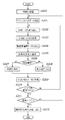
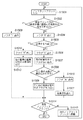
以下、CPU1401が実行する画像符号化用のアプリケーションプログラムの処理手順を図2のフローチャートに従って説明する。基本的に、このプログラムは、図1に示す各構成要素に相当する関数(もしくはサブルーチン)を備えることになる。ただし、図1におけるラインバッファ102、タイルバッファ104、1/2縮小タイルバッファ106、符号化データバッファ109、補間データバッファ112等の各領域はRAM1402内に予め確保することになる。
Hereinafter, the processing procedure of the application program for image encoding executed by the
まず、ステップS200において、符号化を開始する前の初期化処理が行われる。ここでは、符号化対象となる画像データについて符号列に含めるべきヘッダ情報を準備したり、各種メモリ、変数等の初期化処理が行われる。 First, in step S200, initialization processing before starting encoding is performed. Here, header information to be included in the code string is prepared for image data to be encoded, and initialization processing of various memories and variables is performed.
初期化処理の後、ステップS201では、I/F1409によって接続される外部装置から符号化対象の画像データを順次入力し、RAM1402に符号化対象となる画像データの1ストライプ分のデータが格納される(画像入力部101の処理に相当)。
After the initialization process, in step S201, image data to be encoded is sequentially input from an external device connected by the I /
次に、ステップS202では、RAM1402に格納されるストライプについて、着目するタイルデータを切り出し、RAM1402の別のアドレス位置に格納する(タイル分割部103の処理に相当)。
Next, in step S202, the tile data of interest is cut out for the stripe stored in the
続いて、ステップS203において、着目するタイルデータ中の各画素ブロック中の左上隅の画素をサブサンプリングすることで1/2縮小タイルデータを生成し、RAM1402内に格納する(解像度変換部105の処理に相当)。 Subsequently, in step S203, half-reduced tile data is generated by sub-sampling the pixel in the upper left corner of each pixel block in the tile data of interest, and is stored in the RAM 1402 (processing of the resolution conversion unit 105). Equivalent).
ステップS204では、1/2縮小タイルデータから元の解像度のタイルデータを復元するための補間データを生成する(補間データ生成部110の処理に相当)。 In step S204, interpolation data for restoring tile data of the original resolution from the 1/2 reduced tile data is generated (corresponding to the processing of the interpolation data generation unit 110).
ステップS205では、補間データの構造情報から、1/2縮小タイルデータについて可逆と非可逆のどちらの符号化方式を適用するかを決定する(符号化方式選択部111の処理に相当)。 In step S205, it is determined from the structure information of the interpolation data whether to apply the lossless or lossy encoding method to the 1/2 reduced tile data (corresponding to the processing of the encoding method selection unit 111).
選択された符号化方式が可逆符号化である場合(ステップS206)、ステップS207で1/2縮小タイルデータを可逆符号化して符号化データを生成し、RAM1402に格納する(可逆符号化部108の処理に相当)。 When the selected encoding method is lossless encoding (step S206), in step S207, the 1/2 reduced tile data is losslessly encoded to generate encoded data, and stored in the RAM 1402 (of the lossless encoding unit 108). Equivalent to processing).
選択された符号化方式が非可逆符号化である場合(ステップS206)、ステップS208で1/2縮小タイルデータを非可逆符号化して符号化データを生成し、RAM1402に格納する(非可逆符号化部107の処理に相当)。 When the selected encoding method is lossy encoding (step S206), in step S208, the 1/2 reduced tile data is lossy encoded to generate encoded data, and stored in the RAM 1402 (lossy encoding). Equivalent to the processing of the unit 107).
続いて、ステップS209で、着目するタイルについて、タイルヘッダ、可逆/非可逆を識別する情報、補間データ、1/2縮小タイル符号化データを結合させて、タイル符号化データを形成する(符号列形成部113の処理に相当)。 Subsequently, in step S209, the tile encoded data is formed by combining the tile header, information identifying reversible / irreversible, interpolation data, and 1/2 reduced tile encoded data for the target tile (code string). Equivalent to the processing of the forming unit 113).
ステップS210では、符号化処理を行ったタイルが現在読み込まれているストライプの最後のタイルであるか否かを判定する。最後のタイルでない場合には次のタイルについてステップS202から処理を繰り返す。ストライプの最後のタイルである場合には、処理をステップS211へと移す。 In step S210, it is determined whether the tile on which the encoding process has been performed is the last tile of the currently read stripe. If it is not the last tile, the process is repeated from step S202 on the next tile. If it is the last tile of the stripe, the process proceeds to step S211.
ステップS211では、現在読み込まれているストライプが画像の最終ストライプであるか否かを判定する。最終ストライプでない場合にはステップS201に戻り、次のストライプデータを読み込み、処理を継続する。最終ストライプの場合には、ステップS212へと処理を移す。 In step S211, it is determined whether or not the currently read stripe is the final stripe of the image. If it is not the final stripe, the process returns to step S201, the next stripe data is read, and the process is continued. In the case of the final stripe, the process proceeds to step S212.
処理がステップS212に移ったときには、符号化対象画像データのすべてのタイルについて符号化処理が終了しており、RAM1402に格納された全タイルの符号化データから、最終的な符号化データを生成して、I/F1409を解して外部装置へと出力する(符号列形成部113、符号出力部114の処理に相当)。
When the process proceeds to step S212, the encoding process has been completed for all the tiles of the encoding target image data, and final encoded data is generated from the encoded data of all the tiles stored in the
以上説明したように本変形例によっても、第1の実施形態と同様の作用効果を奏することが可能となるのは明らかであろう。すなわち、符号化対象画像を縮小画像と補間データに分解し、縮小画像を補間データの構造によって可逆符号化か非可逆符号化を切り替えて適用することで簡易、高速に高解像度画像の符号化を行うことができる。 As described above, it will be apparent that the present modification can also provide the same operational effects as those of the first embodiment. In other words, the encoding target image is decomposed into a reduced image and interpolation data, and the reduced image is applied by switching between lossless encoding or irreversible encoding depending on the structure of the interpolation data. It can be carried out.
なお、図2に示した処理フローの処理順序は必ずしもこれに限定されるものではない。例えば、1/2縮小タイルデータを生成する処理(ステップS203)、解像度補間データを生成する処理(ステップS204)、符号化方式を選択する処理(ステップS205)などは、解像度補間情報の生成を先に行っても良い。あるいは、処理を統合して行っても構わない。 Note that the processing order of the processing flow shown in FIG. 2 is not necessarily limited to this. For example, the process of generating 1/2 reduced tile data (step S203), the process of generating resolution interpolation data (step S204), the process of selecting an encoding method (step S205), and the like first generate resolution interpolation information. You may go to Alternatively, the processing may be integrated.
[第2の実施形態]
上記第1の実施形態及びその変形例では、解像度補間データを用いて元の解像度の画像を復元する際に適用される補間手法の分布に基づいて、縮小画像を可逆符号化するか、非可逆符号化するかを選択した。しかしながら、解像度補間データの符号量などから、補間手法の分布を推定し、その推定結果に基づいて可逆、非可逆符号化のいずれを実行するかを決定するようにしても、同様の効果を得ることもできる。
[Second Embodiment]
In the first embodiment and the modifications thereof, the reduced image is losslessly encoded or lossy based on the distribution of the interpolation method applied when the original resolution image is restored using the resolution interpolation data. Choose to encode. However, the same effect can be obtained by estimating the distribution of the interpolation method from the code amount of the resolution interpolation data and deciding whether to perform lossless or lossy encoding based on the estimation result. You can also.
そこで、本第2の実施形態として、解像度補間データの符号量に基づいて、符号化方式を選択する手法について説明する。 Therefore, as the second embodiment, a method of selecting an encoding method based on the code amount of resolution interpolation data will be described.
なお、本第2の実施形態でも、対象の画像データは、RGB各色8ビットで構成される画像データとするが、CMYKカラー画像データなど、他の形式の画像データに適用しても良い。また、画像は水平方向W画素、垂直方向H画素により構成されるものとし、タイルのサイズTw,Thは、も第1の実施形態と同じく“32”であるとする。 In the second embodiment, the target image data is image data composed of 8 bits for each color of RGB, but may be applied to image data of other formats such as CMYK color image data. The image is composed of W pixels in the horizontal direction and H pixels in the vertical direction, and the tile sizes Tw and Th are also “32” as in the first embodiment.
本第2の実施形態の画像符号化装置の補間データ生成部110、符号化方式選択部111の処理内容が、第1の実施形態のそれらと異なるだけであり、図1のブロック構成図と基本的に同じであるので、新に図示はしない。
以下、第2の実施形態の処理について、第1の実施形態と動作が異なる補間データ生成部110、符号化方式選択部111の処理内容について説明する。
The processing contents of the interpolation
Hereinafter, the processing contents of the interpolation
上述の第1の実施形態では、補間データ生成部110における補間データ生成の過程でタイル内の各画素ブロックの種類の頻度分布を示すブロック数Na乃至Neを算出し、これを符号化方式選択部111へと提供するとした。これに対し、本第2の実施形態においては、補間データ生成部110は頻度分布の代わりに、着目タイルについての補間データの符号量Lを求め、それを符号化方式選択部111へと提供する。
In the first embodiment described above, the number of blocks Na to Ne indicating the frequency distribution of the type of each pixel block in the tile is calculated in the process of interpolation data generation in the interpolation
符号化方式選択部111は補間データ生成部110から提供される補間データの符号量Lを所定の閾値TH2と比較する。
The encoding
そしてL<TH2ならば可逆符号化を適用するよう、制御信号“1”を出力する。また、L≧TH2ならば非可逆符号化を適用するよう、制御信号“0”を出力する。 If L <TH2, a control signal “1” is output so that lossless encoding is applied. If L ≧ TH2, the control signal “0” is output so that lossy encoding is applied.
1タイルは32×32画素であるので、そのデータ量は32×32×3(RGB成分の数)=3072バイトである。本第2の実施形態では、閾値TH2は、3072バイトの1/8(=384バイト)として説明する。 Since one tile has 32 × 32 pixels, the data amount is 32 × 32 × 3 (number of RGB components) = 3072 bytes. In the second embodiment, the threshold value TH2 is described as 1/8 of 3072 bytes (= 384 bytes).
ここで、第1の実施形態の符号化方式選択部111の説明で述べた、2×2画素の画素ブロックについての種類(a)乃至(e)の5つの種別を考える。これまでの説明から明らかなように、文字、線画、クリップアート画像などで多く出現する種類(a)乃至(c)の場合、補間データとして出力される符号長は短い。一方で、複雑なCGや自然画像で多く見られる種類(d),(e)の場合には、色の情報をそのまま補間データに含めるためのその符号長は大きくなる。これを別な表現で示すと、注目タイルに種類(a)〜(c)のブロックが多く存在する場合には着目タイルの補間データの符号量は少なくなり、逆に種類(d),(e)のブロックが多く含まれる場合には補間データの符号量は多くなる。よって補間データの符号量の量によって第1の実施形態で頻度を参照したのと同様の効果を得ることが可能となる。
Here, the five types of types (a) to (e) for the 2 × 2 pixel block described in the description of the encoding
なお、本第2の実施形態と同等の処理をコンピュータプログラムでもって実現できることは、先に説明した第1の実施形態の変形例から明らかであるので、その説明については省略する。 In addition, since it is clear from the modified example of 1st Embodiment demonstrated previously that it can implement | achieve the process equivalent to this 2nd Embodiment with a computer program, it abbreviate | omits about the description.
[第3の実施形態]
上記第1、第2の実施形態の画像符号化装置では、符号化対象となる画像データを水平、垂直方向共に1/2に縮小し、これを可逆、または、非可逆符号化の対象とした。しかしながら、1/2の縮小に限らず、より小さい画像を生成してビットマップ符号化の対象としても構わない。本第3の実施形態では、その一例として1/2の縮小処理を再帰的に所定回数実行する。そして1回の縮小処理の生成するたびに、縮小元の画像から解像度補間情報を生成する例を説明する。説明を簡単なものとするため、再帰処理回数を2回とする例を以下に説明する。
[Third Embodiment]
In the image encoding devices of the first and second embodiments, the image data to be encoded is reduced to 1/2 in both the horizontal and vertical directions, and this is set as the object of lossless or lossy encoding. . However, the present invention is not limited to 1/2 reduction, and a smaller image may be generated and subjected to bitmap encoding. In the third embodiment, as an example, 1/2 reduction processing is recursively executed a predetermined number of times. An example in which resolution interpolation information is generated from a reduction source image each time one reduction process is generated will be described. In order to simplify the description, an example in which the number of recursive processes is two will be described below.
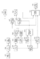
図5に本第3の実施形態における画像符号化装置のブロック構成図を示す。 FIG. 5 shows a block configuration diagram of an image encoding apparatus according to the third embodiment.
第1、第2の実施形態でのブロック図と異なるのは、解像度変換部501、1/4縮小タイルバッファ502、補間データ生成部503が追加された点と、符号化方式選択部111が符号化方式選択部504に置き換わった点である。以下、第2の実施形態と動作の異なる部分について説明する。
The difference from the block diagrams in the first and second embodiments is that a
解像度変換部501は解像度変換部105と同様の処理により、1/2縮小タイルバッファ106に格納される1/2縮小タイルデータを、更に水平、垂直1/2に縮小し、1/4縮小タイルバッファ502へと格納する。
The
補間データ生成部503は1/4縮小タイルバッファに格納される縮小タイルデータから、1/2縮小タイルバッファに格納される1/2縮小タイルデータを復元するために必要な補間データを生成する。ここでの処理は、補間データ生成部110がタイルバッファ104に格納されるタイルデータに対して行うのと同様である。以降、補間データ生成部110が生成する補間データと補間データ生成部503が生成する補間データを区別するため、前者をレベル1補間データと呼び、後者をレベル2補間データと呼ぶ。
The interpolation
補間データバッファ112にはレベル1補間データとレベル2補間データの両方が格納される。
The
符号化方式選択部504には補間データ生成部110、503からそれぞれ、レベル1補間データの符号量L1とレベル2補間データの符号量L2が提供される。符号化方式選択部504は、入力したL1とL2の和を所定のしきい値TH3と比較する。
The encoding
すなわち、L1+L2<TH3ならば可逆符号化を適用するよう、制御信号“1”を出力する。一方、L1+L2≧TH3ならば非可逆符号化を適用するよう、制御信号“0”を出力する。本第3の実施形態では閾値TH3は、元のタイルデータ量3072バイトの1/4、即ち、“768”(バイト)とする。 That is, if L1 + L2 <TH3, the control signal “1” is output so that lossless encoding is applied. On the other hand, if L1 + L2 ≧ TH3, a control signal “0” is output so that lossy encoding is applied. In the third embodiment, the threshold value TH3 is ¼ of the original tile data amount of 3072 bytes, that is, “768” (bytes).
図6は本第3の実施形態で生成される符号列の各タイルの符号化データの構造を図示したものである。1/4縮小タイル符号化データにレベル2補間データ、レベル1補間データを結合させて構成されるた構造となる。 FIG. 6 illustrates the structure of the encoded data of each tile of the code string generated in the third embodiment. The structure is configured by combining the level-2 interpolation data and the level-1 interpolation data with the 1/4 reduced tile encoded data.
本第3の実施形態においても、第1、第2の実施形態と同様に、符号化処理の簡易、高速化が実現できる。高度な演算処理を要するビットマップ符号化処理(非可逆符号化部107、可逆符号化部108による符号化処理)を適用する画素数が元画像データの1/16にまで限定されているため、第1、第2の実施例以上に処理の負荷が軽減される。
In the third embodiment, as in the first and second embodiments, the encoding process can be simplified and speeded up. Since the number of pixels to which bitmap encoding processing (encoding processing by the
なお、本第3の実施形態に相当する処理をコンピュータプログラムでもって実現できることは、先に説明した第1の実施形態の変形例と同様、明らかであるので説明を省略する。 Since it is obvious that the processing corresponding to the third embodiment can be realized by a computer program, as in the modification of the first embodiment described above, the description thereof is omitted.
[第4の実施形態]
上述の第2、第3の実施形態では、補間データの符号量から補間手法の構成を推定して、可逆、非可逆符号化を選択する方法を示した。補間手法の構成を推定は、補間データの一部の符号量からでも可能ある。本第4の実施形態としてこのような例について説明する。
[Fourth Embodiment]
In the second and third embodiments described above, the method of selecting the lossless and lossy encoding by estimating the configuration of the interpolation method from the code amount of the interpolation data is shown. The configuration of the interpolation method can be estimated even from a partial code amount of the interpolation data. Such an example will be described as the fourth embodiment.
本第4の実施形態は、先に説明した第2の実施形態と基本的に同じであるが、補間データ生成部110、符号化方式選択部111の動作が若干異なる。以下、動作の異なる部分について説明する。
The fourth embodiment is basically the same as the second embodiment described above, but the operations of the interpolation
上述の第2の実施形態では、補間データ生成部110において、着目するタイルの補間データ量Lを符号化方式選択部111へと提供した。本第4の実施形態では、第1の実施形態で説明した種類(a)乃至(e)の5種のブロックのうち、種類(d)にかかわる補間データの符号量Ldと、種類(e)にかかわる符号量Leの和を符号化方式選択部111へと提供する。ここでは、種類(d)にかかわる補間データとは、図15の処理フローにおいて、ステップS1510、S1511で処理がなされるノンフラットブロックについて出力される符号を指す。より具体的に述べるならば、ステップS1510、1511に至るノンフラットブロックについて、ステップS1504、S1506、S1507、S1510、S1511で出力される符号である。また種類(e)にかかわる補間データとは、同図、ステップS1512、S1513で処理がなされるノンフラットブロックについて出力される符号を指す。これは、ステップS1512、1513に至るノンフラットブロックについて、ステップS1504、S1512、S1513で出力される符号である。
In the second embodiment described above, the interpolation
符号化方式選択部111は補間データ生成部110から提供される補間データの符号量Ld+Leを所定のしきい値TH4と比較する。Ld+Le<TH4ならば可逆符号化を適用するよう制御信号“1”を出力し、Ld+Le≧TH4ならば非可逆符号化を適用するよう、制御信号“0”を出力する。
The encoding
複雑なCGや自然画では、LdとLeの和が大きくなる傾向にあり、このような画像では非可逆符号化の歪が目に付きにくく、さらに、元の解像度に戻すときにも縮小画像の劣化の影響を受けにくいため、本実施形態においても、高画質、高圧縮、簡易・高速という効果を得ることができる。 In complex CG and natural images, the sum of Ld and Le tends to increase. In such images, distortion of lossy encoding is difficult to be noticed, and even when returning to the original resolution, Since it is difficult to be affected by deterioration, the present embodiment can provide the effects of high image quality, high compression, and simple / high speed.
[その他の実施形態]
上記各実施形態では可逆符号化としてJPEG−LS、非可逆符号化としてJPEGを利用するとして説明したが、先に述べた通り、JPEG2000やPNGなど、他の符号化手法を適用しても構わない。
[Other Embodiments]
In each of the embodiments described above, JPEG-LS is used as lossless encoding and JPEG is used as lossy encoding. However, as described above, other encoding methods such as JPEG2000 and PNG may be applied. .
また、上記の各実施形態では、オリジナル画像から1/2縮小画像を生成する際、2×2画素の画素ブロック内の左上隅に位置する画素Bn(0,0)を縮小画像の画素としてサンプリングし、他の非サンプリング対象の3画素Bn(1,0)、Bn(0,1)、Bn(1,1)の補間データの生成を行った。しかし、縮小画像の利用する画素は必ずしも2×2画素のブロックの左上隅の画素でなくても構わず、Bn(1,0)、Bn(0,1)、Bn(1,1)のいずれであっても構わない。 In each of the above embodiments, when generating a 1/2 reduced image from the original image, the pixel B n (0, 0) located at the upper left corner in the 2 × 2 pixel block is used as the reduced image pixel. Sampling was performed, and interpolation data of other three non-sampling target pixels B n (1, 0), B n (0, 1), B n (1, 1) was generated. However, the pixel used in the reduced image does not necessarily have to be the pixel in the upper left corner of the 2 × 2 pixel block, and B n (1, 0), B n (0, 1), B n (1, 1 ).
要するに、Bn(1,0)、Bn(0,1)、Bn(1,1)のいずれか1つをサンプリング対象の画素Xとした場合であっても、残りの3画素がXa,Xb,Xcと定義できる。この場合、画素Xaを復元するために参照する隣接画素ブロック内の前記画素Xaに隣接するサンプリング対象となる画素をX1、画素Xbを復元するために参照する隣接ブロック内の前記画素Xbに隣接するサンプリング対象となる画素をX2、画素Xcを復元するために参照する隣接ブロック内の前記画素Xcに隣接するサンプリング対象となる画素をX3と定義したとき、
Xa=X1 且つ、
Xb=X2 且つ、
Xc=X3
を満たす場合、その着目画素ブロックは周囲3画素一致ブロックと判定すればよい。
In short, B n (1,0), B n (0,1), also one of B n (1,1) A case of the pixel X of sampled, the remaining 3 pixels Xa , Xb, Xc. In this case, the pixel to be sampled adjacent to the pixel Xa in the adjacent pixel block to be referred to restore the pixel Xa is X1, and the pixel Xb in the adjacent block to be referenced to restore the pixel Xb is adjacent. When the pixel to be sampled is defined as X2, and the pixel to be sampled adjacent to the pixel Xc in the adjacent block referred to for restoring the pixel Xc is defined as X3,
Xa = X1 and
Xb = X2 and
Xc = X3
In the case of satisfying the above, the pixel block of interest may be determined as a peripheral three-pixel matching block.
また、画素ブロックのサイズは3×3画素とし、その中から1画素を抽出することで、水平、垂直ともオリジナルの1/3の画素数の縮小画像を生成しても構わない。 In addition, the size of the pixel block is 3 × 3 pixels, and by extracting one pixel from them, a reduced image having 1/3 the original number of pixels in both horizontal and vertical directions may be generated.
また、画素ブロック中の1画素を抽出するだけでなく、その画素ブロックの平均色を求めて縮小画像を生成するなどしても良い。このような場合、縮小画像の生成方法に応じて、元の解像度の画像データを復元できるように補間データの構成方法を工夫すれば良い。 In addition to extracting one pixel in a pixel block, a reduced image may be generated by obtaining an average color of the pixel block. In such a case, the configuration method of the interpolation data may be devised so that the original resolution image data can be restored according to the reduced image generation method.
また、補間データの構成方法として、元の解像度の画像データが完全に元に戻せるような構成例について示したが、必ずしもこれに限らない。例えば、画素ブロックに含める色数が3色以上である場合には、減色するなどして、元の解像度には戻るものの、画素値としては多少変化することを許容するような補間データとしても良い。 In addition, as a configuration method of the interpolation data, the configuration example in which the image data of the original resolution can be completely restored is shown, but the configuration is not necessarily limited thereto. For example, when the number of colors included in a pixel block is three or more, it may be interpolation data that allows a slight change in the pixel value although it returns to the original resolution by reducing the color. .
また、上述の実施形態では32×32画素のタイルに分割して処理を行ったがタイルの大きさはこれに限定されるものではなく、画素ブロックの整数倍であれば良い。従って。16×16、64×64、128x128など、別のブロックサイズとしても良いし、正方である必要もない。 In the above-described embodiment, processing is performed by dividing the tile into 32 × 32 pixel tiles. However, the size of the tile is not limited to this, and may be an integer multiple of the pixel block. Therefore. Other block sizes such as 16 × 16, 64 × 64, and 128 × 128 may be used, and it is not necessary to be square.
また、実施形態では、画像の色空間はRGBであるとしたが、CMYK、Lab、YCrCbなど様々なタイプの画像データに適用可能であるのは明らかであるので、色成分の数や色空間の種類によって本発明が限定されるものではない。 In the embodiment, the color space of the image is RGB. However, since it is apparent that the present invention can be applied to various types of image data such as CMYK, Lab, and YCrCb, the number of color components and the color space The present invention is not limited by the type.
また、通常、コンピュータプログラムは、CD−ROM等のコンピュータ可読記憶媒体に格納されていて、それをコンピュータの読取り装置(CD−ROMドライブ)にセットし、システムにコピーもしくはインストールすることで実行可能になる。従って、このようなコンピュータ可読記憶媒体も本発明の範疇に入ることも明らかである。 Further, the computer program is usually stored in a computer-readable storage medium such as a CD-ROM, and can be executed by setting it in a computer reader (CD-ROM drive) and copying or installing it in the system. Become. Therefore, it is obvious that such a computer-readable storage medium falls within the scope of the present invention.
Claims (9)
符号化対象の入力画像データ中のN画素に対応する1画素を出力することで、前記入力画像データに対する縮小画像データを生成する縮小画像生成手段と、
前記縮小画像データから、前記入力画像データと同じ解像度の画像データを生成するため、着目N画素の補間手法を複数種類の補間手法から特定する、解像度補間情報を生成する解像度補間情報生成手段と、
前記縮小画像データにおけるブロックを可逆符号化する可逆符号化手段と、
前記ブロックを非可逆符号化する非可逆符号化手段と、
前記縮小画像データにおける着目ブロックに対応する前記解像度補間情報に基づいて、前記可逆符号化手段、前記非可逆符号化手段のいずれか一方を選択し、前記着目ブロックの符号化処理を実行させる選択手段と、
該選択手段による選択された符号化手段より得られた符号化データと、前記解像度補間情報生成手段で生成された解像度補間情報を、前記入力画像データに対する符号化画像データとして出力する出力手段とを備え、
前記解像度補間情報生成手段が生成する解像度補間情報で示される補間方法の種類には、
前記着目N画素を、当該着目N画素に対応する縮小画像中の1画素、又は、当該縮小画像中の1画素の周囲に位置する少なくとも1画素から復元する第1の補間方法、
前記着目N画素を、当該着目N画素の少なくとも一部を前記縮小画像を参照せずに復元する第2の補間方法
が含まれることを特徴とする画像符号化装置。 An image encoding device for encoding image data,
Reduced image generation means for generating reduced image data for the input image data by outputting one pixel corresponding to N pixels in the input image data to be encoded;
Resolution interpolation information generating means for generating resolution interpolation information, specifying an interpolation method for the N pixel of interest from a plurality of types of interpolation methods in order to generate image data having the same resolution as the input image data from the reduced image data;
Lossless encoding means for losslessly encoding blocks in the reduced image data;
Irreversible encoding means for irreversibly encoding the block;
Selection means for selecting one of the lossless encoding means and the lossy encoding means based on the resolution interpolation information corresponding to the block of interest in the reduced image data, and executing the encoding process of the block of interest When,
Encoded data obtained from the encoding means selected by the selection means, and output means for outputting the resolution interpolation information generated by the resolution interpolation information generating means as encoded image data for the input image data. Prepared,
The types of interpolation methods indicated by the resolution interpolation information generated by the resolution interpolation information generating means include:
A first interpolation method for restoring the target N pixel from one pixel in the reduced image corresponding to the target N pixel, or at least one pixel located around one pixel in the reduced image;
An image encoding apparatus comprising: a second interpolation method for restoring the target N pixel without restoring at least a part of the target N pixel without referring to the reduced image.
前記入力画像データ中の総画素数をMとしたとき、前記入力画像データ中のN画素に対応する1画素を出力する処理をM/N回繰り返してM/N画素数の縮小画像データを生成する処理を、再帰的に所定回数実行し、
前記解像度補間情報生成手段は、前記縮小画像生成手段による1回の縮小画像データの生成を行なう度に、縮小元になる画像データから解像度補間情報を生成することを特徴とする請求項1乃至5のいずれか1項に記載の画像符号化装置。 The reduced image generation means includes:
When the total number of pixels in the input image data is M, the process of outputting one pixel corresponding to N pixels in the input image data is repeated M / N times to generate reduced image data with the number of M / N pixels. Recursively execute a predetermined number of times,
6. The resolution interpolation information generation unit generates resolution interpolation information from image data as a reduction source every time the reduced image generation unit generates reduced image data once. The image encoding device according to any one of the above.
符号化対象の入力画像データ中のN画素に対応する1画素を出力することで、前記入力画像データに対する縮小画像データを生成する縮小画像生成工程と、
前記縮小画像データから、前記入力画像データと同じ解像度の画像データを生成するため、着目N画素の補間手法を複数種類の補間手法から特定する、解像度補間情報を生成する解像度補間情報生成工程と、
前記縮小画像データにおけるブロックを可逆符号化する可逆符号化工程と、
前記ブロックを非可逆符号化する非可逆符号化工程と、
前記縮小画像データにおける着目ブロックに対応する前記解像度補間情報に基づいて、前記可逆符号化工程、前記非可逆符号化工程のいずれか一方を選択し、前記着目ブロックの符号化処理を実行させる選択工程と、
該選択工程による選択された符号化工程より得られた符号化データと、前記解像度補間情報生成工程で生成された解像度補間情報を、前記入力画像データに対する符号化画像データとして出力する出力工程とを備え、
前記解像度補間情報生成工程が生成する解像度補間情報で示される補間方法の種類は、
前記着目N画素を、当該着目N画素に対応する縮小画像中の1画素、又は、当該縮小画像中の1画素の周囲に位置する少なくとも1画素から復元する第1の補間方法、
前記着目N画素を、当該着目N画素の少なくとも一部を前記縮小画像を参照せずに復元する第2の補間方法
が含まれることを特徴とする画像符号化装置の制御方法。 A control method for an image encoding device for encoding image data, comprising:
A reduced image generation step of generating reduced image data for the input image data by outputting one pixel corresponding to N pixels in the input image data to be encoded;
A resolution interpolation information generating step for generating resolution interpolation information, specifying an interpolation method for the N pixel of interest from a plurality of types of interpolation methods in order to generate image data having the same resolution as the input image data from the reduced image data;
A lossless encoding step of losslessly encoding blocks in the reduced image data;
An irreversible encoding step of irreversibly encoding the block;
A selection step of selecting one of the lossless encoding step and the lossy encoding step based on the resolution interpolation information corresponding to the block of interest in the reduced image data, and executing the encoding process of the block of interest When,
An encoded data obtained from the selected encoding process in the selecting process, and an output process for outputting the resolution interpolation information generated in the resolution interpolation information generating process as encoded image data for the input image data; Prepared,
The type of interpolation method indicated by the resolution interpolation information generated by the resolution interpolation information generation step is:
A first interpolation method for restoring the target N pixel from one pixel in the reduced image corresponding to the target N pixel, or at least one pixel located around one pixel in the reduced image;
A control method for an image encoding device, comprising: a second interpolation method for restoring the target N pixel without restoring at least a part of the target N pixel without referring to the reduced image.
Priority Applications (2)
| Application Number | Priority Date | Filing Date | Title |
|---|---|---|---|
| JP2008315030A JP5116650B2 (en) | 2008-12-10 | 2008-12-10 | Image coding apparatus and control method thereof |
| US12/620,241 US8396308B2 (en) | 2008-12-10 | 2009-11-17 | Image coding based on interpolation information |
Applications Claiming Priority (1)
| Application Number | Priority Date | Filing Date | Title |
|---|---|---|---|
| JP2008315030A JP5116650B2 (en) | 2008-12-10 | 2008-12-10 | Image coding apparatus and control method thereof |
Publications (3)
| Publication Number | Publication Date |
|---|---|
| JP2010141533A true JP2010141533A (en) | 2010-06-24 |
| JP2010141533A5 JP2010141533A5 (en) | 2011-12-22 |
| JP5116650B2 JP5116650B2 (en) | 2013-01-09 |
Family
ID=42231139
Family Applications (1)
| Application Number | Title | Priority Date | Filing Date |
|---|---|---|---|
| JP2008315030A Expired - Fee Related JP5116650B2 (en) | 2008-12-10 | 2008-12-10 | Image coding apparatus and control method thereof |
Country Status (2)
| Country | Link |
|---|---|
| US (1) | US8396308B2 (en) |
| JP (1) | JP5116650B2 (en) |
Cited By (3)
| Publication number | Priority date | Publication date | Assignee | Title |
|---|---|---|---|---|
| JP2011223462A (en) * | 2010-04-13 | 2011-11-04 | Canon Inc | Image encoding device and control method thereof |
| JP2012054842A (en) * | 2010-09-02 | 2012-03-15 | Canon Inc | Image processing device and processing method thereof |
| JP2012054786A (en) * | 2010-09-01 | 2012-03-15 | Canon Inc | Image processor, image processing method, and program |
Families Citing this family (3)
| Publication number | Priority date | Publication date | Assignee | Title |
|---|---|---|---|---|
| JP5777398B2 (en) * | 2011-05-13 | 2015-09-09 | キヤノン株式会社 | Image processing apparatus, image processing method and program for image processing apparatus |
| US10110931B2 (en) | 2016-04-27 | 2018-10-23 | Aspeed Technology Inc. | Variable length coding and decoding methods and devices for grouped pixels |
| US10609418B2 (en) * | 2017-04-18 | 2020-03-31 | Qualcomm Incorporated | System and method for intelligent data/frame compression in a system on a chip |
Citations (3)
| Publication number | Priority date | Publication date | Assignee | Title |
|---|---|---|---|---|
| JPH0981763A (en) * | 1995-07-07 | 1997-03-28 | Oki Data:Kk | Method and device for compressing character and image mixed data |
| JPH11146394A (en) * | 1997-11-05 | 1999-05-28 | Fuji Xerox Co Ltd | Image analyzer and image coding decoder |
| JP2008042687A (en) * | 2006-08-08 | 2008-02-21 | Canon Inc | Image processing apparatus and its control method, computer program and computer readable storage medium |
Family Cites Families (26)
| Publication number | Priority date | Publication date | Assignee | Title |
|---|---|---|---|---|
| JPS56103773A (en) * | 1980-01-21 | 1981-08-19 | Agency Of Ind Science & Technol | Feature extracing system of binary pattern |
| US4525748A (en) * | 1982-07-30 | 1985-06-25 | Carbone Anthony K | Method and apparatus for scanning and digitizing optical images |
| US4709394A (en) * | 1985-08-23 | 1987-11-24 | Rca Corporation | Multiplexed real-time pyramid signal processing system |
| JP2787832B2 (en) * | 1989-06-30 | 1998-08-20 | キヤノン株式会社 | Image reduction method |
| JP2523222B2 (en) * | 1989-12-08 | 1996-08-07 | ゼロックス コーポレーション | Image reduction / enlargement method and apparatus |
| US5144688A (en) * | 1990-03-23 | 1992-09-01 | Board Of Regents, The University Of Texas System | Method and apparatus for visual pattern image coding |
| US5583953A (en) * | 1993-06-30 | 1996-12-10 | Xerox Corporation | Intelligent doubling for low-cost image buffers |
| JP3373008B2 (en) * | 1993-10-20 | 2003-02-04 | オリンパス光学工業株式会社 | Image area separation device |
| JP2000511363A (en) * | 1994-07-14 | 2000-08-29 | ジョンソン、グレイス、カンパニー | Method and apparatus for compressing images |
| JPH08167030A (en) | 1994-12-15 | 1996-06-25 | Canon Inc | Device and method for image compression |
| JPH10173913A (en) | 1996-12-13 | 1998-06-26 | Minolta Co Ltd | Image forming device |
| US5862268A (en) * | 1997-03-24 | 1999-01-19 | Focus Enhancements, Inc. | Bilinear decimator with error compensation |
| JP3861957B2 (en) * | 1998-02-03 | 2006-12-27 | ソニー株式会社 | Storage device, writing method and reading method |
| US6373890B1 (en) * | 1998-05-05 | 2002-04-16 | Novalogic, Inc. | Video compression and playback process |
| US6304339B1 (en) * | 1998-11-16 | 2001-10-16 | Hewlett-Packard Company | Compound document page data processing |
| JP3596863B2 (en) * | 1999-11-26 | 2004-12-02 | シャープ株式会社 | Image compression device and image decompression device, and computer-readable recording medium in which a program for causing a computer to execute the image compression method and the image decompression method is recorded. |
| US7139099B2 (en) * | 2000-02-23 | 2006-11-21 | Fuji Xerox Co., Ltd. | Image processing device and image processing method |
| JP3680931B2 (en) | 2000-02-23 | 2005-08-10 | 富士ゼロックス株式会社 | Image processing apparatus and image processing method |
| US6868186B1 (en) * | 2000-07-13 | 2005-03-15 | Ceva D.S.P. Ltd. | Visual lossless image compression |
| US6915020B2 (en) * | 2001-12-19 | 2005-07-05 | Hewlett-Packard Development Company, L.P. | Generating graphical bar codes by halftoning with embedded graphical encoding |
| US7545997B2 (en) * | 2004-09-10 | 2009-06-09 | Xerox Corporation | Simulated high resolution using binary sub-sampling |
| JP4371026B2 (en) * | 2004-09-28 | 2009-11-25 | コニカミノルタビジネステクノロジーズ株式会社 | Printing system and printer |
| US20060291751A1 (en) * | 2004-12-16 | 2006-12-28 | Peyman Milanfar | Robust reconstruction of high resolution grayscale images from a sequence of low-resolution frames (robust gray super-resolution) |
| CN101543036B (en) * | 2006-11-24 | 2011-10-26 | 日本电气株式会社 | Coding and decoding device, coding and decoding method |
| JP4495745B2 (en) * | 2007-04-18 | 2010-07-07 | キヤノン株式会社 | Image processing apparatus, image processing method, computer program, and storage medium |
| WO2011027440A1 (en) * | 2009-09-02 | 2011-03-10 | 株式会社 東芝 | Image compression device and image decompression device |
-
2008
- 2008-12-10 JP JP2008315030A patent/JP5116650B2/en not_active Expired - Fee Related
-
2009
- 2009-11-17 US US12/620,241 patent/US8396308B2/en not_active Expired - Fee Related
Patent Citations (3)
| Publication number | Priority date | Publication date | Assignee | Title |
|---|---|---|---|---|
| JPH0981763A (en) * | 1995-07-07 | 1997-03-28 | Oki Data:Kk | Method and device for compressing character and image mixed data |
| JPH11146394A (en) * | 1997-11-05 | 1999-05-28 | Fuji Xerox Co Ltd | Image analyzer and image coding decoder |
| JP2008042687A (en) * | 2006-08-08 | 2008-02-21 | Canon Inc | Image processing apparatus and its control method, computer program and computer readable storage medium |
Cited By (3)
| Publication number | Priority date | Publication date | Assignee | Title |
|---|---|---|---|---|
| JP2011223462A (en) * | 2010-04-13 | 2011-11-04 | Canon Inc | Image encoding device and control method thereof |
| JP2012054786A (en) * | 2010-09-01 | 2012-03-15 | Canon Inc | Image processor, image processing method, and program |
| JP2012054842A (en) * | 2010-09-02 | 2012-03-15 | Canon Inc | Image processing device and processing method thereof |
Also Published As
| Publication number | Publication date |
|---|---|
| US8396308B2 (en) | 2013-03-12 |
| US20100142840A1 (en) | 2010-06-10 |
| JP5116650B2 (en) | 2013-01-09 |
Similar Documents
| Publication | Publication Date | Title |
|---|---|---|
| KR101177799B1 (en) | Image encoding apparatus and method of controlling the same | |
| US7912300B2 (en) | Image processing apparatus and control method therefor | |
| US8983185B2 (en) | Image compression | |
| US8509310B2 (en) | Method, medium, and system encoding and/or decoding an image | |
| JP4902569B2 (en) | Image coding apparatus and control method thereof | |
| JP5393574B2 (en) | Image processing apparatus, image processing method, and program | |
| US8660345B1 (en) | Colorization-based image compression using selected color samples | |
| JP5116650B2 (en) | Image coding apparatus and control method thereof | |
| JP2005348390A (en) | Image coding apparatus, image decoding apparatus, their control methods, computer program, and computer-readable storage medium | |
| JP2007182060A (en) | Image processing device and its control method | |
| JP2013542667A (en) | Video intra prediction method and apparatus | |
| AU2007249106A1 (en) | A lossless compressor for image data values | |
| JP2008042683A (en) | Image processing apparatus and its control method, computer program and computer readable storage medium | |
| JP2006080793A (en) | Image coder, method, compputer program, and computer readable storage medium | |
| JP5538985B2 (en) | Image coding apparatus and control method thereof | |
| JP5933987B2 (en) | Image coding apparatus and control method thereof | |
| JP5432690B2 (en) | Image coding apparatus and control method thereof | |
| JP2008042681A (en) | Image processing method and processor, computer program and computer readable storage medium | |
| JP2008109478A (en) | Image encoding device, method, program and storage medium | |
| AU2008249145A1 (en) | Resolution independent image degradation | |
| JP4795160B2 (en) | Image processing apparatus, control method therefor, computer program, and computer-readable storage medium | |
| JP2013038656A (en) | Image encoder and control method of the same | |
| JP5523177B2 (en) | Image coding apparatus and control method thereof | |
| JP2012095227A (en) | Image processing system, image processing method, and program | |
| JP2007281591A (en) | Image processing apparatus and program |
Legal Events
| Date | Code | Title | Description |
|---|---|---|---|
| A521 | Written amendment |
Free format text: JAPANESE INTERMEDIATE CODE: A523 Effective date: 20100412 |
|
| A521 | Written amendment |
Free format text: JAPANESE INTERMEDIATE CODE: A523 Effective date: 20111109 |
|
| A621 | Written request for application examination |
Free format text: JAPANESE INTERMEDIATE CODE: A621 Effective date: 20111109 |
|
| A977 | Report on retrieval |
Free format text: JAPANESE INTERMEDIATE CODE: A971007 Effective date: 20120911 |
|
| TRDD | Decision of grant or rejection written | ||
| A01 | Written decision to grant a patent or to grant a registration (utility model) |
Free format text: JAPANESE INTERMEDIATE CODE: A01 Effective date: 20120918 |
|
| A01 | Written decision to grant a patent or to grant a registration (utility model) |
Free format text: JAPANESE INTERMEDIATE CODE: A01 |
|
| A61 | First payment of annual fees (during grant procedure) |
Free format text: JAPANESE INTERMEDIATE CODE: A61 Effective date: 20121016 |
|
| R151 | Written notification of patent or utility model registration |
Ref document number: 5116650 Country of ref document: JP Free format text: JAPANESE INTERMEDIATE CODE: R151 |
|
| FPAY | Renewal fee payment (event date is renewal date of database) |
Free format text: PAYMENT UNTIL: 20151026 Year of fee payment: 3 |
|
| LAPS | Cancellation because of no payment of annual fees |