JP2010141385A - Device for selecting main object - Google Patents
Device for selecting main object Download PDFInfo
- Publication number
- JP2010141385A JP2010141385A JP2008312982A JP2008312982A JP2010141385A JP 2010141385 A JP2010141385 A JP 2010141385A JP 2008312982 A JP2008312982 A JP 2008312982A JP 2008312982 A JP2008312982 A JP 2008312982A JP 2010141385 A JP2010141385 A JP 2010141385A
- Authority
- JP
- Japan
- Prior art keywords
- subject
- locus
- unit
- input
- motion
- Prior art date
- Legal status (The legal status is an assumption and is not a legal conclusion. Google has not performed a legal analysis and makes no representation as to the accuracy of the status listed.)
- Pending
Links
Images


Landscapes
- Studio Devices (AREA)
Abstract
Description
本発明は、被写体の選択を画面上でおこなう装置に関する。 The present invention relates to an apparatus for selecting a subject on a screen.
特許文献1の例えば図11に記載された装置は、撮像された画像を表示する液晶ディスプレイ(LCD)上にタッチパネルを有する。ユーザは被写体を選択するためにこのタッチパネルを触る。装置は、タッチパネル上での押圧位置(触れた位置)に対応する被写体を選択する。
上述の装置を用いるユーザは、選択を希望する被写体をタッチパネル上で触る。しかし被写体を選択するとき、被写体の動きが速い場合、またはランダムである場合、被写体をタッチパネル上で正確に押圧することが難しい。タッチパネル上で被写体を触ろうとしたときに、別のオブジェクトが希望の被写体と重なることもある。このような場合も、被写体をタッチパネル上で正確に押圧することが難しい。 A user using the above-described device touches a subject desired to be selected on the touch panel. However, when selecting a subject, if the subject moves quickly or randomly, it is difficult to press the subject accurately on the touch panel. When trying to touch the subject on the touch panel, another object may overlap the desired subject. Even in such a case, it is difficult to accurately press the subject on the touch panel.
本発明の目的は、被写体の容易な選択を可能にする装置を提供することである。 An object of the present invention is to provide an apparatus that allows easy selection of a subject.
本発明による被写体選択装置は、被写体を連続するフレーム群に撮像する撮像部と、前記フレーム群のそれぞれにおける前記被写体の位置を検出する検出部と、前記被写体の位置を含む動作軌跡を算出する動作軌跡算出部と、前記動作軌跡を表示する表示部と、前記表示部と関連付けられた、ユーザから入力を受け取る入力部と、前記入力に基づいて押圧位置を算出する入力データ生成部と、前記動作軌跡と、前記押圧位置とを比較することによって前記被写体を選択する比較部とを備える。 An object selection device according to the present invention includes an imaging unit that images a subject in a continuous frame group, a detection unit that detects the position of the subject in each of the frame groups, and an operation that calculates an operation locus including the position of the subject. A trajectory calculation unit, a display unit for displaying the motion trajectory, an input unit associated with the display unit for receiving input from a user, an input data generation unit for calculating a pressed position based on the input, and the operation A comparison unit that selects the subject by comparing the locus and the pressed position;
ある実施形態によれば、前記比較部は、前記動作軌跡と、前記押圧位置との距離を比較することによって前記被写体を選択する。 According to an embodiment, the comparison unit selects the subject by comparing a distance between the motion locus and the pressed position.
ある実施形態によれば、前記比較部は、前記動作軌跡の方向と、前記押圧位置の軌跡の方向とを比較することによって前記被写体を選択する。 According to an embodiment, the comparison unit selects the subject by comparing the direction of the motion locus with the direction of the locus of the pressed position.
ある実施形態によれば、前記比較部は、前記動作軌跡の形状と、前記押圧位置の軌跡の形状とを比較することによって前記被写体を選択する。 According to an embodiment, the comparison unit selects the subject by comparing the shape of the motion locus with the shape of the locus of the pressed position.
本発明による装置は、ユーザが触った点、またはユーザが触った点群からなる軌跡と、被写体の動作軌跡とを比較する。この比較に基づいて、複数の被写体の中からユーザが選択したターゲット被写体を特定できる。本発明は、ユーザが複数の被写体の中から希望の被写体を容易に選択できる効果を有する。 The apparatus according to the present invention compares a trajectory composed of points touched by the user or a group of points touched by the user with the motion trajectory of the subject. Based on this comparison, the target subject selected by the user from the plurality of subjects can be identified. The present invention has an effect that a user can easily select a desired subject from a plurality of subjects.
本発明のある実施形態による装置は、ユーザが触った点と、被写体の動作軌跡との距離を比較する。この比較に基づいて、複数の被写体の中からユーザが選択したターゲット被写体を特定できる。本実施形態は、被写体または被写体の動作軌跡そのものを触ることを必要とせず、その近傍をユーザが触ることによって複数の被写体の中から希望の被写体を容易に選択できる効果を有する。 An apparatus according to an embodiment of the present invention compares the distance between a point touched by a user and a motion locus of a subject. Based on this comparison, the target subject selected by the user from the plurality of subjects can be identified. This embodiment has an effect that it is not necessary to touch the subject or the motion locus of the subject itself, and the user can easily select a desired subject from a plurality of subjects by touching the vicinity thereof.
本発明の他の実施形態による装置は、ユーザが触った点群からなる軌跡と、被写体の動作軌跡との距離を比較する。この比較に基づいて、複数の被写体の中からユーザが選択したターゲット被写体を特定できる。本実施形態は、被写体または被写体の動作軌跡そのものを触ることを必要とせず、その近傍をユーザが触ることによって複数の被写体の中から希望の被写体を容易に選択できる効果を有する。 An apparatus according to another embodiment of the present invention compares the distance between a locus made up of points touched by a user and the movement locus of a subject. Based on this comparison, the target subject selected by the user from the plurality of subjects can be identified. This embodiment has an effect that it is not necessary to touch the subject or the motion locus of the subject itself, and the user can easily select a desired subject from a plurality of subjects by touching the vicinity thereof.
本発明のさらに他の実施形態による装置は、ユーザが触った点群からなる軌跡の向きと、被写体の動作軌跡の向きとを比較する。この比較に基づいて、複数の被写体の中からユーザが選択したターゲット被写体を特定できる。本実施形態は、被写体または被写体の動作軌跡そのものを触ることを必要とせず、被写体の動作軌跡の向きに沿ってユーザがなぞることによって複数の被写体の中から希望の被写体を容易に選択できる効果を有する。 An apparatus according to still another embodiment of the present invention compares the direction of a trajectory composed of point clouds touched by a user and the direction of a motion trajectory of a subject. Based on this comparison, the target subject selected by the user from the plurality of subjects can be identified. This embodiment does not require touching the subject or the motion trajectory of the subject itself, and allows the user to easily select a desired subject from a plurality of subjects by tracing along the direction of the motion trajectory of the subject. Have.
本発明のさまざまな実施形態によれば、ターゲット被写体の動作軌跡またはその近傍をなぞることによって、複数の被写体の中から希望の被写体を選択することができる。これら実施形態は、選択したい被写体の動きが速い、または被写体の動きがランダムな場合、および選択したい被写体が別のオブジェクトと重なっている場合でも、タッチパネル上で被写体の動作軌跡の近傍をなぞることによって、ターゲット被写体を容易に選択できる効果を有する。 According to various embodiments of the present invention, a desired subject can be selected from a plurality of subjects by tracing the motion locus of the target subject or the vicinity thereof. In these embodiments, when the subject to be selected moves quickly or randomly, and even when the subject to be selected overlaps another object, by tracing the vicinity of the motion locus of the subject on the touch panel The target subject can be easily selected.
図面を参照して例示的実施形態を以下に詳細に説明する。 Exemplary embodiments are described in detail below with reference to the drawings.
(システム構成)
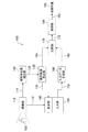
図1は、例示的実施形態によるシステム100の構成を示す。一例としてシステム100は、デジタルビデオカメラであり得る。しかしシステム100は、動画または静止画を表示するディスプレイ、およびディスプレイに関連付けられたタッチパネルを有する任意の電子機器に応用可能である。そのような電子機器の例には、テレビ、デジタルカメラ、パーソナルコンピュータなどが含まれる。
(System configuration)
FIG. 1 shows a configuration of a
システム100は、撮像部110、被写体位置検出部(単に「検出部」とも呼ぶ)120、動作軌跡算出部130、表示部140、入力部150、入力データ算出部160、比較部170、および制御部180を含む。
The
撮像部110は、レンズ系を通し、動画を撮像し、撮像された動画を表す電気信号112を表示部140に出力する。このような動画は、撮像時刻に対応付けられた複数の連続するフレーム群(例えば1秒間に60フレーム)からなる。動画は、典型的には動く被写体102を含む。撮像部110は撮像素子を含む。撮像素子の例には、CCD(電荷結合素子)イメージセンサ、CMOS(相補性金属酸化膜半導体)イメージセンサ、撮像管などが含まれる。
The
表示部140は、撮像部110から受け取られた信号112に基づいて、撮像された動画を表示する。表示部140は、撮像された動画以外の情報(例えば時刻、録画可能な残り時間など)を表示してもよい。典型的には表示部140は、LCD(液晶ディスプレイ)パネルである。表示部140の代替の実現例には、プラズマディスプレイパネル、EL(エレクトロルミネセンス)パネルが含まれる。
The
被写体位置検出部120は、撮像部110によって出力された信号114を受け取る。信号114は、典型的には被写体102を含む動画を表す。被写体位置検出部120は、動画を構成する複数の連続するフレーム群のそれぞれにおける被写体102の位置を特定する。具体的には、被写体位置検出部120は、被写体102の例えば特徴点を検出し、その特徴点の位置を特定する。被写体位置検出部120は、特定された特徴点の位置情報122を、被写体102の位置として、動作軌跡算出部130に出力する。
The subject
動作軌跡算出部130は、複数のフレーム群における被写体102の位置に基づいて、被写体102の動作軌跡132、134を算出する。単一のフレーム内に複数の被写体102が存在することもありえる。そのような場合は、複数の被写体102のそれぞれについて動作軌跡132、134を算出する。
The motion
表示部140は、信号112によって表される前述の撮像された動画とオーバラップさせて、被写体102の動作軌跡132を表示する。撮像された動画に複数の被写体102が存在するときは、表示部140は、複数の被写体102に対応する複数の動作軌跡132を表示する。
The
入力部150は、表示部140の表示スクリーンに対応付けられた板状の位置入力デバイス(例えばタッチパッドと呼ばれる)を有する。そのような位置入力デバイスは、マトリクス・スイッチ、抵抗膜、表面弾性波、赤外線、および静電容量などの任意の1つを利用して実現され得る。図1において表示部140および入力部150は、2つの機能ブロックとして表現される。しかし表示部140および入力部150は、別個の要素(例えば電子部品)である必要はなく、一体化して形成され得る。
The
ユーザは、表示部140に表示された典型的には複数である被写体の中から1つを選択するために、入力部150において希望の被写体に対応する位置を押圧する。入力部150は、表示部140におけるユーザによって押圧された位置を表す信号152を発生し、入力データ生成部160に出力する。
The user presses a position corresponding to a desired subject on the
本明細書で「押圧位置」とは、典型的にはユーザが押さえた入力部150上の単一または複数の位置(群)を指す。ユーザが入力部150上の一点で押圧した場合、押圧位置は、単一の座標を表す。ユーザが入力部150上である軌跡をなぞるように、一連の点群において押圧した場合、押圧位置は、入力軌跡に対応する複数の座標群を表す。
In this specification, the “pressing position” typically refers to a single or a plurality of positions (groups) on the
入力データ生成部160は、入力部150によって出力された信号152に基づいて、ユーザによって押圧された位置の座標を算出する。入力データ生成部160は、押圧位置を表す信号162を比較部170に出力する。
The input
比較部170は、動作軌跡算出部130によって算出された被写体の動作軌跡134と、入力データ生成部160によって算出された押圧位置座標162とを比較することによって、「ターゲット被写体」(主要被写体とも呼ばれる)を選択する。このターゲット被写体は、ユーザがその被写体のパラメータ(例えば明るさ、色調、フォーカス)を調整することを希望する被写体であって、典型的には複数の被写体の中の特定の1つである。比較部170によって実行される比較のタイプに依存して、本システム100は、さまざまな手法によって希望の被写体を選択し得る。それら手法は、実施形態1〜6について以下に説明される。比較部170は、選択された被写体の現在の位置を表す信号172を制御部180に出力する。
The
制御部180は、受け取られた位置情報172に基づいて、フレーム内のその位置に対応する画像を調整する。つまり制御部180は、制御対象190に所望の調整をおこなう指示182を与える。そのような調整の例には、明るさ補正、色調補正、焦点調整がある。画像に対する制御部180がおこなう調整は、自動でおこなわれてもよく、またはユーザがなんらかの指示を与えることによってそれに基づいておこなわれてもよい。
Based on the received
例えば、制御部180は、逆光の状態にあるターゲット被写体の明るさを明るく補正することができる。代替として、制御部180は、現在の状態ではフォーカスが合っていないターゲット被写体にフォーカスが合うよう、レンズ系を駆動することができる。よって前者の例では、制御部180は、位置情報172が表す画素の明るさを調整する指示182を制御対象190である画像処理装置に出力する。後者の例では、制御部180は、位置情報172が表す画素のフォーカスを調整する指示182を制御対象190であるレンズ駆動系に出力する。
For example, the
被写体位置検出部120、動作軌跡算出部130、入力データ生成部160、比較部170、および制御部180の機能の全部または一部は、ハードウェア、ソフトウェア、またはハードウェアおよびソフトウェアの任意の適当な組み合わせによって実現され得る。そのようなハードウェアの例には、IC(集積回路)、LSI(大規模集積回路)、ASIC(特定用途向け集積回路)などがある。
All or some of the functions of the subject
(実施形態1)
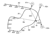
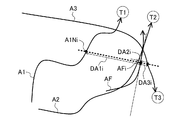
図1〜3を参照して説明されるシステム100は、ポイント(点)モードによって希望の被写体を選択する。ポイントモードにおいては、ユーザは入力部150上で被写体の近傍の点を触ることによって、ターゲット被写体を選択する。図2は、撮像部110によって撮像された複数の被写体T1、T2、T3、および対応する動作軌跡A1、A2、A3を示す。被写体位置検出部120は、撮像部110によって撮像された連続するフレームのそれぞれにおける複数の被写体T1、T2、T3の位置を検出する。動作軌跡算出部130は、複数の被写体T1、T2、T3の位置に基づいて、対応する動作軌跡A1、A2、A3を算出する。
(Embodiment 1)
The
一般的に、撮像中に被写体が動くと、撮像されたフレーム内での被写体の位置も変わる。被写体自体が静止していても撮像部110がパンやチルトをおこなうと、フレーム内での被写体の位置は変わる。さまざまな実施形態においては、これら両方の場合が考慮される。いずれの状況においても、複数のフレームにわたってフレーム内での被写体T1の位置が変化することが想定される。被写体位置検出部120は、それぞれのフレーム内での被写体T1の位置を動作軌跡算出部130に出力する。
Generally, when the subject moves during imaging, the position of the subject within the captured frame also changes. Even if the subject itself is stationary, if the
動作軌跡算出部130は、被写体T1の複数の位置に基づいて、動作軌跡A1を発生し、表示部140に出力する。同様に、表示部140は、被写体T2およびT3にそれぞれ対応する動作軌跡A2およびA3も表示する。被写体T1、T2、T3が実質的に静止していれば、対応する動作軌跡は1点または密集した点群になり得る。動作軌跡は、連続するフレームにおける被写体のそれぞれの位置を、例えば曲線に当てはめることによって求められる。そのような曲線の例には、2次曲線、3次曲線、スプライン曲線、ベジエ曲線などがある。動作軌跡は、曲線当てはめ以外の手法によって算出されてもよい。例えば複数の被写体位置を直線によって結んだ多角形による曲線近似を利用してもよい。
The motion
入力データ生成部160によって算出された押圧位置座標は、図2の入力位置座標Arに対応する。図2において入力位置座標Arと、動作軌跡A1、A2、A3との距離は、それぞれDA1、DA2、DA3である。例えば、ユーザが被写体T2を選択したい場合、ユーザは、距離DA2がDA1およびDA3よりも短くなるような点Arを押圧する。換言すれば、システム100は、距離DA1、DA2、DA3のうち、どれが最小か(図2ではDA2が最小)を判断し、最小距離に対応する被写体(図2でT2)を選択する。
The pressed position coordinates calculated by the input
多くの場合、ユーザは複数の被写体の中から特定の1つ(ターゲット被写体)を選択する必要がある。システム100は、ユーザによる容易な被写体選択を実現し得る。システム100は、ユーザが選択した被写体に合わせた制御(例えば明るさ補正)を可能にする。比較部170は、選択された被写体(例えばT2)に対応する位置を制御部180へ与える。制御部180は、受け取られた位置情報に基づいて、フレーム内のその位置に対応する画像に合わせた調整をおこなう。そのような調整の例には、明るさ補正、色調補正、焦点調整がある。
In many cases, the user needs to select a specific one (target subject) from a plurality of subjects. The
例えばユーザが、歩いている3人の子供(複数の被写体)をシステム100(例えばビデオカメラ)によって撮影していると想定する。ユーザは、複数の被写体を表示部140で見ながら、ターゲット被写体(例えば3人の子供のうちの1人)の顔に明るさを合わせたい。ユーザは、入力部150上でターゲット被写体(例えばT2)の動作軌跡(例えばA2)の近くを触る。これによりシステムは、ユーザがターゲット被写体を選択したと認識できる。制御部180は、選択された被写体の位置に対応する画素の明るさが適当な範囲に入るように、明るさを調整する。
For example, it is assumed that the user is photographing three children (a plurality of subjects) walking with the system 100 (for example, a video camera). The user wants to adjust the brightness of the face of the target subject (for example, one of three children) while viewing a plurality of subjects on the
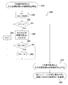
図3は、後述するコントローラ(例えばマイクロプロセッサ)が実行するプロセス300の操作フローを示す。プロセス300は、比較部170が、ポイントモードにおいて、複数の被写体(例えば図2のT1、T2、T3)から、ターゲット被写体(例えば図2のT2)を選択できるようにする。図3において、距離DA1は、押圧位置Arと、動作軌跡A1上の点との距離の中で最小の距離である。本明細書では簡単のために、距離DA1は、「押圧位置Arからの動作軌跡A1の距離」と呼ぶ。同様に、距離DA2およびDA3は、それぞれ動作軌跡A2およびA3の距離である。ポイントモードは、距離DA1、DA2、DA3のうちで最小の距離に対応する動作軌跡を選択する。
FIG. 3 shows an operation flow of a
310において、比較部170は、入力位置座標Arと、被写体Tjに対応する動作軌跡Ajとを受け取る。添え字jは、被写体を表す。例えば比較部170が被写体T1、T2、T3にそれぞれ対応する動作軌跡Aj(j=1,2,3)を受け取る場合、添え字j=1,2,3についてフロー300が実行される。3個の被写体Tjに対応する動作軌跡上のn個のサンプリング点を、一般にAjk(j=1,2,3;k=1,…,n)(j,k:自然数)と表す。添え字kは、フレーム内で時間に依存して連続的に動く被写体位置のサンプリング点の順序を表す。
In 310, the
320において、コントローラは、kの初期値を1に設定し、DAjの初期値を例えば65535に設定する。DAjの初期値は、後述する最小値の算出のための十分に大きい値であればよい。よって、DAjの初期値は、任意の適当な自然数であり得る。330において、コントローラは、添え字kがn以下であるかを判定する。もし330での判定がYES(添え字kがn以下)なら、コントローラは、340〜360の操作を繰り返し実行する。340において、コントローラは、押圧位置座標Arと、被写体Tjに対応する動作軌跡上の点Ajkとの距離Dkを算出する。 At 320, the controller sets the initial value of k to 1 and sets the initial value of DAj to, for example, 65535. The initial value of DAj may be a sufficiently large value for calculating the minimum value described later. Therefore, the initial value of DAj can be any appropriate natural number. In 330, the controller determines whether the subscript k is n or less. If the determination in 330 is YES (subscript k is n or less), the controller repeatedly executes the operations of 340 to 360. In 340, the controller calculates a distance Dk between the pressed position coordinate Ar and a point Ajk on the motion trajectory corresponding to the subject Tj.
350において、コントローラは、DkがDAjより小さいかを判定する。もし350での判定がYES(DkがDAjより小さい)なら、コントローラは、360においてDkの値をDAjに代入し、365へ進む。もし350での判定がNO(DkがDAjより小さくはない)なら、365へ進む。 At 350, the controller determines whether Dk is less than DAj. If the determination at 350 is YES (Dk is less than DAj), the controller assigns the value of Dk to DAj at 360 and proceeds to 365. If the determination at 350 is NO (Dk is not smaller than DAj), the process proceeds to 365.
365において、コントローラは、kの値を1だけ増してから、330に進む。もし330での判定がNO(添え字kがnを超える)なら、コントローラは、370において入力位置座標Arと、被写体Tjの動作軌跡Ajとの距離をDAjとする。被写体Tjがp個(p:自然数)存在する場合は、操作310〜370を繰り返し実行することによって、動作軌跡Aj(j=1,…,p;p:自然数)に対応する距離DAjを求める。
At 365, the controller increments the value of k by 1 before proceeding to 330. If the determination at 330 is NO (subscript k is greater than n), the controller sets the distance between the input position coordinate Ar and the motion trajectory Aj of the subject Tj to DAj at 370. When there are p subjects (p: natural number), the
380において、コントローラは、DAj(j=1,…,p;p:自然数)の中で最も小さい距離に対応する被写体Tjを選択する。比較部170は、380において選択された被写体Tjの位置情報172を制御部180に出力する。
In 380, the controller selects a subject Tj corresponding to the smallest distance among DAj (j = 1,..., P; p: natural number). The
図2の場合、動作軌跡A1、A2、A3は、同じ個数(n個)のサンプリング点から構成される。しかしサンプリング点の個数はn個には限定されず、より一般的には、動作軌跡A1、A2、A3は、異なる個数のサンプリング点から構成され得る。 In the case of FIG. 2, the motion trajectories A1, A2, A3 are composed of the same number (n) of sampling points. However, the number of sampling points is not limited to n, and more generally, the motion trajectories A1, A2, and A3 can be composed of different numbers of sampling points.
(実施形態2)
図1、図4および図5を参照して説明されるシステム100は、トレースモードによって希望の被写体を選択する。トレースモードにおいては、ユーザは入力部上で被写体の動作軌跡をなぞる(トレースする)ことによってターゲット被写体を選択する。図1を参照したシステム100の説明は、実施形態2にも適用される。
(Embodiment 2)
The
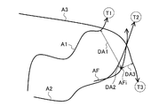
図2および図3を参照したポイントモードと比べ、トレースモードにおいては、ユーザは、ターゲット被写体の動作軌跡上を押圧したまま、トレースすることによって被写体を選択する。図4は、このようなユーザによるトレースの軌跡AFを示す。入力データ生成部160は、入力軌跡AFを算出する。入力軌跡AFと、複数の被写体T1、T2、T3にそれぞれ対応する動作軌跡A1、A2、A3との距離は、距離DA1、DA2、DA3と呼ばれる。
Compared to the point mode with reference to FIG. 2 and FIG. 3, in the trace mode, the user selects a subject by tracing while keeping pressing on the motion trajectory of the target subject. FIG. 4 shows a trace locus AF of such a user. The input
図5は、コントローラ(例えばマイクロプロセッサ)が実行するプロセス500の操作フローを示す。プロセス500は、比較部170が、トレースモードにおいて、複数の被写体(例えば図4のT1、T2、T3)から、ターゲット被写体(例えば図4のT2)を選択できるようにする。図4において、距離DA1は、入力軌跡AF上の特定のサンプリング点AFiと、動作軌跡A1上の点との距離の中で最小の距離である。本明細書では簡単のために、距離DA1は、「サンプリング点AFiからの動作軌跡A1の距離」と呼ぶ。同様に、距離DA2およびDA3は、サンプリング点AFiからのそれぞれ動作軌跡A2およびA3の距離である。
FIG. 5 shows an operational flow of a
一般に入力軌跡AF上には、m個(m:自然数)のサンプリング点AFi(i=1,…,m)が存在する。もしユーザが入力部150を触る指を動かさないなら、ただ1個のサンプリング点AFi(i=1)が存在し得る。トレースモードは、距離DA1、DA2、DA3のうちで最小の距離に対応する動作軌跡を選択する。ここで複数のサンプリング点AFi(i=1,…,m)からの動作軌跡Ajの距離DAjの総和をSDAj(図4ではj=1,2,3)とする。トレースモードは、距離SDA1、SDA2、SDA3のうちで最小の距離に対応する動作軌跡(図4ではA2)を選択する。
In general, there are m (m: natural number) sampling points AFi (i = 1,..., M) on the input locus AF. If the user does not move the finger touching the
510において、比較部170は、複数のサンプリング点AFi(i=1,…,m)からなる入力軌跡AFと、被写体Tjに対応する動作軌跡Ajとを受け取る。添え字iはサンプリング点の順序を表す。添え字jは、被写体を表す。例えば比較部170が被写体T1、T2、T3にそれぞれ対応する動作軌跡Aj(j=1,2,3)を受け取る場合、添え字j=1,2,3についてフロー500が実行される。3個の被写体Tjに対応する動作軌跡上のn個のサンプリング点を、一般にAjk(j=1,2,3;k=1,…,n)(j,k:自然数)と表す。添え字kは、フレーム内で時間に依存して連続的に動く被写体位置のサンプリング点の順序を表す。
In 510, the
520において、コントローラは、iの初期値を1に設定し、kの初期値を1に設定し、DAjの初期値を例えば65535に設定し、SDAjの初期値を0に設定する。DAjの初期値は、後述する最小値の算出のための十分に大きい値であればよい。よって、DAjの初期値は、任意の適当な自然数であり得る。525において、コントローラは、添え字iがm以下であるかを判定する。もし525での判定がYES(添え字iがm以下)なら、コントローラは、530〜560の操作を繰り返し実行する。540において、コントローラは、サンプリング点AFiと、被写体Tjに対応する動作軌跡上の点Ajkとの距離Dkiを算出する。 In 520, the controller sets the initial value of i to 1, sets the initial value of k to 1, sets the initial value of DAj to, for example, 65535, and sets the initial value of SDAj to 0. The initial value of DAj may be a sufficiently large value for calculating the minimum value described later. Therefore, the initial value of DAj can be any appropriate natural number. In 525, the controller determines whether the subscript i is less than or equal to m. If the determination at 525 is YES (subscript i is less than or equal to m), the controller repeatedly executes the operations of 530 to 560. In 540, the controller calculates a distance Dki between the sampling point AFi and the point Ajk on the motion trajectory corresponding to the subject Tj.
530において、コントローラは、添え字kがn以下であるかを判定する。もし530での判定がYES(添え字kがn以下)なら、コントローラは、540〜560の操作を繰り返し実行する。540において、コントローラは、サンプリング点AFiと、被写体Tjに対応する動作軌跡上の点Ajkとの距離Dkiを算出する。 In 530, the controller determines whether the subscript k is n or less. If the determination at 530 is YES (subscript k is n or less), the controller repeatedly executes the operations of 540 to 560. In 540, the controller calculates a distance Dki between the sampling point AFi and the point Ajk on the motion trajectory corresponding to the subject Tj.
550において、コントローラは、DkiがDAjより小さいかを判定する。もし550での判定がYES(DkがDAjより小さい)なら、コントローラは、560においてDkの値をDAjに代入し、565へ進む。もし550での判定がNO(DkがDAjより小さくはない)なら、565へ進む。 At 550, the controller determines whether Dki is less than DAj. If the determination at 550 is YES (Dk is less than DAj), the controller assigns the value of Dk to DAj at 560 and proceeds to 565. If the determination at 550 is NO (Dk is not smaller than DAj), the process proceeds to 565.
565において、コントローラは、kの値を1だけ増してから、530に進む。もし530での判定がNO(添え字kがnを超える)なら、コントローラは570において、現在のSDAjとDAjとの和を新しいSDAjとする。580において、コントローラはiの値を1だけ増す。 At 565, the controller increments the value of k by 1 before proceeding to 530. If the determination at 530 is NO (subscript k is greater than n), at 570, the controller sets the sum of the current SDAj and DAj as the new SDAj. At 580, the controller increments the value of i by one.
もし525での判定がNO(添え字iがm以下ではない)なら、コントローラは、585へ進む。585において、コントローラは、入力軌跡AF上のサンプリング点AFiと、被写体Tjの動作軌跡Ajとの距離の総和をSDAjとする。被写体Tjがp個(p:自然数)存在する場合は、操作510〜580を繰り返し実行することによって、動作軌跡Aj(j=1,…,p)に対応する距離SDAjを求める。
If the determination at 525 is NO (subscript i is not less than or equal to m), the controller proceeds to 585. In 585, the controller sets SDAj as the sum of the distances between the sampling points AFi on the input trajectory AF and the motion trajectory Aj of the subject Tj. When p subjects Tj (p: natural number) exist,
590において、コントローラは、SDAj(j=1,…,p)の中で最も小さい距離に対応する被写体Tjを選択する。比較部170は、590において選択された被写体Tjの位置情報172を制御部180に出力する。
In 590, the controller selects a subject Tj corresponding to the smallest distance among SDAj (j = 1,..., P). The
図4の場合、動作軌跡A1、A2、A3は、同じ個数(n個)のサンプリング点から構成される。しかしサンプリング点の個数はn個には限定されず、より一般的には、動作軌跡A1、A2、A3は、異なる個数のサンプリング点から構成され得る。 In the case of FIG. 4, the motion trajectories A1, A2, A3 are composed of the same number (n) of sampling points. However, the number of sampling points is not limited to n, and more generally, the motion trajectories A1, A2, and A3 can be composed of different numbers of sampling points.
(実施形態3)
図1および図6を参照して説明されるシステム100は、トレースモードによって希望の被写体を選択する。トレースモードにおいては、ユーザは入力部上で被写体の動作軌跡をなぞることによってターゲット被写体を選択する。図1を参照したシステム100の説明は、実施形態3にも適用される。
(Embodiment 3)
The
図6に示される本トレースモードにおいては、実施形態2と同様にユーザがターゲット被写体の動作軌跡をトレースすることによって被写体を選択する。図6は、このようなユーザによるトレースの軌跡AFを示す。軌跡AFは、典型的には複数のサンプリング点AFi(i=1,…,m;m=自然数)からなる。入力データ生成部160は、入力軌跡AFを算出する。
In the trace mode shown in FIG. 6, the user selects a subject by tracing the movement locus of the target subject as in the second embodiment. FIG. 6 shows such a trace AF AF by the user. The locus AF is typically composed of a plurality of sampling points AFi (i = 1,..., M; m = natural number). The input
比較部170は、動作軌跡134に基づいて、入力軌跡AF上のサンプリング点AFiにおける法線AFNiを算出する。比較部170は、法線AFNiに沿った、サンプリング点AFiと、動作軌跡A1、A2、A3との距離を算出する。これら距離は、距離DA1i、DA2i、DA3iと呼ばれる。例えば図6において、入力軌跡上の点AFiについての法線AFNiと、動作軌跡A1との交点をA1Niとする。距離DA1iは、点AFiと、点A1Niとの距離である。同様にして距離DA2i、DA3iは、点AFiにおける法線に沿った距離として定義される。
The
比較部170は、入力軌跡AFの全サンプリング点(i=1,…,m;m=自然数)について、DA1i、DA2i、DA3iを算出する。比較部170は、距離DA1i、DA2i、DA3iをi=1,…,m(m=自然数)について総和することによって、それぞれ距離総和SDA1、SDA2、SDA3を求める。比較部170は、距離総和SDA1、SDA2、SDA3の中で最小値を決定し、その最小値に対応する被写体Tjを選択する。比較部170は、選択された被写体Tjの位置情報172を制御部180に出力する。
The
(実施形態4)
図1および図7を参照して説明されるシステム100は、トレースモードによって希望の被写体を選択する。トレースモードにおいては、ユーザは入力部上で被写体の動作軌跡をなぞることによってターゲット被写体を選択する。図1を参照したシステム100の説明は、実施形態4にも適用される。
(Embodiment 4)
The
図7に示される本トレースモードにおいては、実施形態2と同様にユーザがターゲット被写体の動作軌跡をトレースすることによって被写体を選択する。図7は、このようなユーザによるトレースの軌跡AFを示す。軌跡AFは、典型的には複数のサンプリング点AFi(i=1,…,m;m=自然数)からなる。入力データ生成部160は、入力軌跡AFを算出する。比較部170は、入力軌跡AFに幅を付すことによって、入力軌跡バンドAFBを算出する。入力軌跡バンドAFBの幅は、所定の固定された値であり得る。代替としてそのような幅は、例えばユーザの指定を受け付ける手段によって設定された値であり得る。
In the trace mode shown in FIG. 7, the user selects a subject by tracing the movement locus of the target subject as in the second embodiment. FIG. 7 shows such a trace AF AF by the user. The locus AF is typically composed of a plurality of sampling points AFi (i = 1,..., M; m = natural number). The input
比較部170は、それぞれの被写体T1、T2、T3について、サンプリング点Ajk(j=1,2,3;k=1,…,n)(j,k:自然数)が領域AFBに含まれるか否かを判定し、領域AFBに含まれるサンプリング点の個数を算出する。比較部170は、含まれるサンプリング点Ajkが最多である軌跡Ajに対応する被写体Tjを選択する。
The
(実施形態5)
図1および図8を参照して説明されるシステム100は、トレースモードによって希望の被写体を選択する。トレースモードにおいては、ユーザは入力部上で被写体の動作軌跡をなぞることによってターゲット被写体を選択する。図1を参照したシステム100の説明は、実施形態5にも適用される。
(Embodiment 5)
The
図8に示される本トレースモードにおいては、実施形態2と同様にユーザがターゲット被写体の動作軌跡をトレースすることによって被写体を選択する。図8は、このようなユーザによるトレースの軌跡AFを示す。軌跡AFは、典型的には複数のサンプリング点AFi(i=1,…,m;m=自然数)からなる。入力データ生成部160は、入力軌跡AFを算出する。比較部170は、入力軌跡AFの始点から終点への方向を表す、入力方向IDを算出する。
In the trace mode shown in FIG. 8, the user selects a subject by tracing the motion trajectory of the target subject as in the second embodiment. FIG. 8 shows a trace AF AF by such a user. The locus AF is typically composed of a plurality of sampling points AFi (i = 1,..., M; m = natural number). The input
比較部170は、複数の被写体T1、T2、T3に対応する動作軌跡A1、A2、A3についても、それぞれの軌跡の始点または任意の過去の点から現在の点への方向を表す動作方向MDj(j=1,2,3)を算出する。入力方向IDおよび動作方向MDjは、例えば2次元ベクトルによって表現され得る。システム100は、そのような2次元ベクトルを例えば2つの変数(x,y)のペアとして定義し、計算し得る。
The
比較部170は、入力方向IDと、各動作方向MDjとがなす差分角を求める。一般に2つのベクトルの差分角を求めるには、それらベクトルの内積を求めればよい。比較部170は、差分角が最小である動作方向MDjに対応する被写体Tjを選択する。比較部170は、選択された被写体Tjの位置情報172を制御部180に出力する。
The
(実施形態6)
図1および図9を参照して説明されるシステム100は、トレースモードによって希望の被写体を選択する。トレースモードにおいては、ユーザは入力部上で被写体の動作軌跡をなぞることによってターゲット被写体を選択する。図1を参照したシステム100の説明は、実施形態6にも適用される。
(Embodiment 6)
The
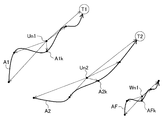
図9に示される本トレースモードにおいては、実施形態2と同様にユーザがターゲット被写体の動作軌跡をトレースすることによって被写体を選択する。図9は、このようなユーザによるトレースの軌跡AFを示す。軌跡AFは、典型的には複数のサンプリング点AFi(i=1,…,m;m=自然数)からなる。入力データ生成部160は、入力軌跡AFを算出する。
In the trace mode shown in FIG. 9, the user selects a subject by tracing the movement locus of the target subject as in the second embodiment. FIG. 9 shows such a trace locus AF by the user. The locus AF is typically composed of a plurality of sampling points AFi (i = 1,..., M; m = natural number). The input
比較部170は、動作軌跡Ajにおいてn個のサンプリングをおこない、サンプリング点Ajk(j=1,2,3;k=1,…,n)の平均位置Unj(j=1,2,3)を算出する。比較部170は、各動作軌跡Ajにおいて、平均位置Unjを始点とし、各サンプリング点Ajkを終点とするベクトルを算出する。比較部170は、各動作軌跡において前記ベクトルをサンプリング順に並べたベクトル列TAjを求め、その大きさを正規化し、STAjとする。
The
各動作軌跡と同様に、入力軌跡についても比較部170は、n個のサンプリングをおこない、サンプリング点AFkの平均位置を求めWnとする。平均位置UnjおよびWnは、システム100が扱う仮想的な2次元平面内における位置である。本明細書における平均位置は、例えば、各点のx成分、y成分の相加平均をそのx成分、y成分として有する点である。
As with each motion trajectory, the
比較部170は、各サンプリング点において、Wnを始点とし、各サンプリング点AFkを終点とするベクトルを算出する。比較部170は、入力軌跡において前記ベクトルをサンプリング順に並べたベクトル列TAFを求め、その大きさを正規化し、STAFとする。比較部170は、ベクトル列STAFと、ベクトル列STAjとのペアを順次、比較することによって、ベクトルの角度差が少なく、かつ大きさが近いベクトル列TAjに対応する被写体Tjを選択する。比較部170は、選択された被写体Tjの位置情報172を制御部180に出力する。
The
本実施形態では、押圧したままで触る点を動かすことによって入力された軌跡全てを入力軌跡として用いる。しかし入力された軌跡の一部、例えば入力の前半部分または入力の後半部分等を入力軌跡として用いてもよい。 In the present embodiment, all the trajectories input by moving the touched point while being pressed are used as the input trajectory. However, a part of the input trajectory, for example, the first half of the input or the second half of the input may be used as the input trajectory.
本実施形態では被写体の動作軌跡の移動向きと、入力軌跡の移動向きに関しては区別しない。しかし被写体の動作軌跡Ajの移動向きと、入力軌跡AFの移動向きとを考慮することによって、おおむね逆方向である動作軌跡Ajに対応する被写体Tjを無視しても(すなわち選択しなくても)よい。被写体の動作軌跡の向きと、入力軌跡の向きとの関係を評価するためには、比較部170は、例えば、入力軌跡の始点位置と、被写体の動作軌跡の時系列順のサンプリング位置との関係を比較し得る。
In the present embodiment, no distinction is made regarding the movement direction of the motion locus of the subject and the movement direction of the input locus. However, by considering the movement direction of the movement locus Aj of the subject and the movement direction of the input locus AF, the subject Tj corresponding to the movement locus Aj that is generally in the reverse direction can be ignored (ie, not selected). Good. In order to evaluate the relationship between the direction of the motion trajectory of the subject and the direction of the input trajectory, the
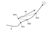
図10および図11は、被写体の動作軌跡の向きと、入力軌跡の向きとの関係を評価する手法を示す。比較部170は、入力軌跡AFの始点位置AFSからの、被写体Tの動作軌跡Aの時系列順のサンプリング位置(AS1,AS2,AS3)の距離を順次比較する。図10に示される場合においては、この距離は、おおむね長くなる傾向にある。よって、入力軌跡AFの向きと、被写体Tの動作軌跡Aの向きとは、おおむね同じ方向と判断され得る。よって図10の動作軌跡Aは、入力軌跡AFと向きがほぼ同じであるので、対応する被写体Tは選択される。
10 and 11 show a method for evaluating the relationship between the direction of the motion trajectory of the subject and the direction of the input trajectory. The
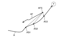
一方、図11に示される場合においては、この距離は、おおむね短くなる傾向にある。よって、入力軌跡AFの向きと、被写体Tの動作軌跡Aの向きとは、おおむね反対の方向と判断され得る。よって図11の動作軌跡Aは、入力軌跡AFと向きがほぼ反対であるので、対応する被写体Tも選択されない。 On the other hand, in the case shown in FIG. 11, this distance tends to be shorter. Therefore, the direction of the input trajectory AF and the direction of the motion trajectory A of the subject T can be determined to be generally opposite directions. Therefore, since the motion trajectory A in FIG. 11 is substantially opposite in direction to the input trajectory AF, the corresponding subject T is not selected.
以上、本発明の実施形態1〜6は、図面を参照して詳細に説明された。 As mentioned above, Embodiment 1-6 of this invention was described in detail with reference to drawings.
上述の実施形態1〜6においては、その動作軌跡の任意の適当な点を、ターゲットの動作軌跡の開始点(例えば図2のA11、A21、A31)として選ぶことができる。しかし現在のフレームから所定数のフレーム数だけ時間的に遡ったフレームにおける被写体の位置を、動作軌跡の開始点として選んでもよい。代替として、現在の被写体の位置から所定の長さだけ動作軌跡に沿って離れた点を、動作軌跡の始点として選ぶこともできる。さらには、表示部140内に表示され得る動作軌跡上の点のうち、動作軌跡に沿って最も現在の被写体の位置から離れた点を、動作軌跡の始点として選ぶこともできる。いずれの場合も被写体の現在位置を動作軌跡の終点として用いればよい。
In the above-described first to sixth embodiments, any appropriate point of the motion trajectory can be selected as the start point of the target motion trajectory (for example, A11, A21, A31 in FIG. 2). However, the position of the subject in a frame that is temporally retroactive from the current frame may be selected as the start point of the motion trajectory. Alternatively, a point that is separated from the current subject position along the motion trajectory by a predetermined length can be selected as the start point of the motion trajectory. Furthermore, among points on the motion trajectory that can be displayed in the
上において自然数i,j,k,m,n,pは、実施形態に応じて適宜、任意の値をとり得る。例えば動作軌跡Ajにおいては、自然数jが1〜3をとるとして説明されたが、これには限定されない。動作軌跡Ajがフレーム中に1つしか存在しないときは、j=1が成立する。 In the above, the natural numbers i, j, k, m, n, and p can take arbitrary values as appropriate according to the embodiment. For example, in the motion trajectory Aj, the natural number j has been described as 1 to 3, but the present invention is not limited to this. When only one motion locus Aj exists in the frame, j = 1 holds.
実施形態1〜6のプロセスを実行するのに用いられるコントローラは、典型的にはマイクロプロセッサである。代替としてこのコントローラは、他のハードウェアによって、またはハードウェアおよびソフトウェアの任意の適当な組み合わせによって実現され得る。例えば、コントローラの機能は、IC、LSI、ASICのような半導体チップの形で実現され得る。代替として、これら機能は、マイクロプロセッサ上で走るソフトウェアによっても実現され得る。 The controller used to perform the processes of embodiments 1-6 is typically a microprocessor. Alternatively, the controller can be implemented by other hardware or by any suitable combination of hardware and software. For example, the function of the controller can be realized in the form of a semiconductor chip such as an IC, LSI, or ASIC. Alternatively, these functions can also be realized by software running on a microprocessor.
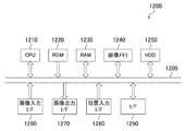
図12は、システム100の機能ブロックを実現するコントローラ1200のブロック図である。コントローラ1200は、CPU(中央処理ユニット)1210、ROM(読み出し専用メモリ)1220、RAM(ランダムアクセスメモリ)1230、画像メモリ1240、HDD(ハードディスクドライブ)1250、画像入力I/F(インタフェース)1260、画像出力I/F1270、位置入力I/F1280、およびI/F1290を有する。コントローラ1200のこれら要素は、システムバス1205によって結合されることによって、データを一方向または両方向にやりとりできる。データの方向を表す図中の矢印は、一例であり、これには限られない。例えばHDD1250が読み出し専用に設定される場合は、データは、一方向にだけ転送される。
FIG. 12 is a block diagram of a
CPU1210は、典型的にはIC、LSI、ASICなどによって実現され得る。ROM1220は、必要な機能ブロックを達成するソフトウェアプログラムを永久的に格納する。RAM1230は、CPU1210の主記憶装置として、さまざまなプログラムまたはデータを一時的に格納する。画像メモリ1240は、システム100が表示部140に表示する画像を一時的に格納する。HDD1250は、システム100が長期的に保存するプログラムまたはデータを格納する。コントローラ1200の機能は、CPUおよびメモリなどによらず、シーケンサとして実現されてもよい。
The
画像入力I/F1260は、撮像部110に結合され、撮像された画像を受け取る。画像出力I/F1270は、表示部140に結合され、例えば動作軌跡132を出力する。位置入力I/F1280は、入力部150に結合され、ユーザによる押圧位置に対応するデータ152を受け取る。I/F1290は、外部の機器とさまざまなデータをやりとりする。例えばI/F1290は、ネットワークを介してデータをやりとりするネットワークI/Fであり得る。
The image input I /
コントローラ1200は、その全体または一部がワンチップのICとして実現され得る。代替としてコントローラ1200は、複数の半導体チップから構成されてもよい。
The
本発明による装置は、被写体の動作軌跡と、ユーザによって入力された押圧位置とを比較することによって被写体を選択でき、被写体選択装置等の用途に適用できる。 The apparatus according to the present invention can select a subject by comparing the motion trajectory of the subject and the pressed position input by the user, and can be applied to uses such as a subject selection device.
110 撮像部
120 被写体位置検出部
130 動作軌跡算出部
140 表示部
150 入力部
160 入力データ生成部
170 比較部
180 制御部
DESCRIPTION OF
Claims (4)
前記フレーム群のそれぞれにおける前記被写体の位置を検出する検出部と、
前記被写体の位置を含む動作軌跡を算出する動作軌跡算出部と、
前記動作軌跡を表示する表示部と、
前記表示部上でのユーザによる押圧を検出する入力部と、
前記押圧に基づいて押圧位置を算出する入力データ生成部と、
前記動作軌跡と、前記押圧位置とを比較することによって前記被写体を選択する比較部と
を備える被写体選択装置。 An imaging unit for imaging a subject in a continuous frame group;
A detection unit for detecting the position of the subject in each of the frame groups;
An operation trajectory calculation unit for calculating an operation trajectory including the position of the subject;
A display unit for displaying the movement locus;
An input unit for detecting a press by the user on the display unit;
An input data generation unit that calculates a pressing position based on the pressing;
A subject selection device comprising: a comparison unit that selects the subject by comparing the movement locus and the pressed position.
Priority Applications (1)
| Application Number | Priority Date | Filing Date | Title |
|---|---|---|---|
| JP2008312982A JP2010141385A (en) | 2008-12-09 | 2008-12-09 | Device for selecting main object |
Applications Claiming Priority (1)
| Application Number | Priority Date | Filing Date | Title |
|---|---|---|---|
| JP2008312982A JP2010141385A (en) | 2008-12-09 | 2008-12-09 | Device for selecting main object |
Publications (1)
| Publication Number | Publication Date |
|---|---|
| JP2010141385A true JP2010141385A (en) | 2010-06-24 |
Family
ID=42351158
Family Applications (1)
| Application Number | Title | Priority Date | Filing Date |
|---|---|---|---|
| JP2008312982A Pending JP2010141385A (en) | 2008-12-09 | 2008-12-09 | Device for selecting main object |
Country Status (1)
| Country | Link |
|---|---|
| JP (1) | JP2010141385A (en) |
Cited By (1)
| Publication number | Priority date | Publication date | Assignee | Title |
|---|---|---|---|---|
| JP2012191544A (en) * | 2011-03-14 | 2012-10-04 | Olympus Imaging Corp | Reproduction apparatus, imaging apparatus, and moving image reproduction program |
-
2008
- 2008-12-09 JP JP2008312982A patent/JP2010141385A/en active Pending
Cited By (1)
| Publication number | Priority date | Publication date | Assignee | Title |
|---|---|---|---|---|
| JP2012191544A (en) * | 2011-03-14 | 2012-10-04 | Olympus Imaging Corp | Reproduction apparatus, imaging apparatus, and moving image reproduction program |
Similar Documents
| Publication | Publication Date | Title |
|---|---|---|
| US10761610B2 (en) | Vehicle systems and methods for interaction detection | |
| JP6153564B2 (en) | Pointing device with camera and mark output | |
| JP7457082B2 (en) | Reactive video generation method and generation program | |
| CN109565551B (en) | Synthesizing images aligned to a reference frame | |
| JP6419278B1 (en) | Control device, control method, and program | |
| US20150220776A1 (en) | Identification of a gesture | |
| KR101608423B1 (en) | Full 3d interaction on mobile devices | |
| US20150206002A1 (en) | Object tracking in a video stream | |
| TWI496094B (en) | Gesture recognition module and gesture recognition method | |
| JP7267753B2 (en) | Control device, control method, and program | |
| JP5220157B2 (en) | Information processing apparatus, control method therefor, program, and storage medium | |
| KR20150106824A (en) | Gesture recognition apparatus and control method of gesture recognition apparatus | |
| WO2021000686A1 (en) | Gesture control method, gesture-controlled device and storage medium | |
| JP6632681B2 (en) | Control device, control method, and program | |
| TWI499938B (en) | Touch control system | |
| US20160062406A1 (en) | Information processing device, image projection apparatus, and information processing method | |
| JP6229554B2 (en) | Detection apparatus and detection method | |
| WO2011096571A1 (en) | Input device | |
| JP2010141385A (en) | Device for selecting main object | |
| US20150103005A1 (en) | Pointing device using camera and outputting mark | |
| US20200409527A1 (en) | Image processing device, imaging device, method of controlling image processing device, and recording medium | |
| JP7434385B2 (en) | Control device, control method, and program | |
| JP7210388B2 (en) | IMAGE PROCESSING DEVICE, IMAGING DEVICE, CONTROL METHOD AND PROGRAM FOR IMAGE PROCESSING DEVICE | |
| JP2016224888A (en) | Information processing apparatus, coordinate estimation program, and coordinate estimation method | |
| TWI566128B (en) | Virtual control device |