JP2010136593A - Wire arrangement structure of wire harness for automobile - Google Patents
Wire arrangement structure of wire harness for automobile Download PDFInfo
- Publication number
- JP2010136593A JP2010136593A JP2008312462A JP2008312462A JP2010136593A JP 2010136593 A JP2010136593 A JP 2010136593A JP 2008312462 A JP2008312462 A JP 2008312462A JP 2008312462 A JP2008312462 A JP 2008312462A JP 2010136593 A JP2010136593 A JP 2010136593A
- Authority
- JP
- Japan
- Prior art keywords
- wire harness
- slide
- slider
- overstroke
- slide member
- Prior art date
- Legal status (The legal status is an assumption and is not a legal conclusion. Google has not performed a legal analysis and makes no representation as to the accuracy of the status listed.)
- Granted
Links
Images


Abstract
Description
本発明は自動車用ワイヤハーネスの配索構造に関し、詳しくは、車体とスライド部材との間に架け渡されるワイヤハーネスの渡り部の長さを、スライド部材のオーバーストローク時を考慮して長めに設定しなくても、オーバーストロークに対応できるものである。 The present invention relates to a wiring structure for a wire harness for an automobile, and more specifically, the length of a wire harness that is bridged between a vehicle body and a slide member is set to be longer in consideration of an overstroke of the slide member. Even if it does not do, it can respond to an overstroke.
従来、自動車のスライドドアなどのスライド部材内の電装品に常時給電するために、車体とスライド部材との間にワイヤハーネスが架け渡されている。この種の配索構造として、例えば、図8に示すように、複数のリンク部材1を線状に連結させたキャタピラ状のケーブルガイド2にワイヤハーネスW/Hを挿通し、前記ケーブルガイド2の両端部を車体3とスライドドア4とに設けられた回転機構を備えた支持部材5、6に連結してワイヤハーネスW/Hを支持部材5、6に支持させることにより、車体3とスライドドア4との間にワイヤハーネスW/Hを渡り配索する構造が提案されている(特開2006−327328号公報参照)。前記キャタピラ状のケーブルガイド2は、電線を保護する機能のほか、ワイヤハーネスW/Hの屈曲を制御し、車体とのクリアランスをとることによって周辺部材との干渉を防止する機能を有している。
2. Description of the Related Art Conventionally, a wire harness is bridged between a vehicle body and a slide member in order to constantly supply power to electrical components in a slide member such as an automobile slide door. As this type of wiring structure, for example, as shown in FIG. 8, a wire harness W / H is inserted into a caterpillar-
また、前記ケーブルガイド2にかえて、環状の山部と谷部が軸線方向に交互に設けられたコルゲートチューブをワイヤハーネスの外装材として用い、その両端部を、回転機構を設けた支持部材に支持させる場合もある。
In addition, instead of the
一方、スライドドアを急開または急閉すると、スライドドアがオーバーストロークする場合がある。スライド部材のオーバーストロークとは、スライド部材の通常のスライド量を超えてスライドすることをいい、前記スライド部材がスライドドアの場合には、スライドドアの急開や急閉によって、通常のドア開閉動作によるドア全開位置あるいはドア全閉位置を通り越した地点までスライドすることをいう。例えば、スライドドアを備えた乗用車の場合、スライド完了位置であるドア全開位置あるいはドア全閉位置を通過して20〜30mmの地点までオーバーストロークする場合があり、その後、スライドドアはドア全開位置、ドア全閉位置に戻される。 On the other hand, when the sliding door is opened or closed rapidly, the sliding door may overstroke. The overstroke of the slide member refers to sliding beyond the normal slide amount of the slide member. When the slide member is a slide door, the normal door opening / closing operation is performed by rapidly opening or closing the slide door. It means to slide to a point that passes the door fully open position or door fully closed position. For example, in the case of a passenger car equipped with a slide door, it may overstroke to a point of 20 to 30 mm after passing through the door fully open position or the door fully closed position, which is a slide completion position. The door is returned to the fully closed position.
前記のようなワイヤハーネスの配索構造では、スライドドア4がオーバーストロークすると、車体側の支持部材5からスライドドア側の支持部材6までの距離が広がるため、車体3とスライドドア4との間に架け渡すワイヤハーネスW/Hの渡り部の長さは、スライドドア4のオーバーストローク時を考慮して、通常の開閉動作のために必要な長さより長めに設定する必要がある。しかし、前記構成とすると、スライドドア4の通常の開閉時には、ワイヤハーネスW/Hのオーバーストローク分の長さが余分となって渡り部に弛みが生じ、見栄えが悪化すると共に、乗員の乗降などの際に前記弛んだ渡り部が踏み付けられワイヤハーネスが損傷するおそれもある。
In the wiring structure of the wire harness as described above, since the distance from the
本発明は前記問題に鑑みてなされたものであり、車体とスライド部材との間に架け渡されるワイヤハーネスの渡り部の長さをスライド部材のオーバーストローク時を考慮して長めに設定しなくてもオーバーストロークに滑らかに対応でき、よって、ワイヤハーネスの渡り部の弛みを防止できることを課題としている。 The present invention has been made in view of the above problems, and it is not necessary to set the length of the connecting portion of the wire harness spanned between the vehicle body and the slide member longer in consideration of the overstroke of the slide member. It is also an object of the present invention to be able to smoothly cope with the overstroke, and thus to prevent looseness of the crossover of the wire harness.
前記課題を解決するため、本発明は、車体とスライド部材との間に架け渡されるワイヤハーネスの配索構造であって、
前記ワイヤハーネスを車体側に設けた支持部材とスライド部材側に設けた支持部材とで支持し、
前記スライド部材側には、前記ワイヤハーネスを挿通保持したスライダーを設け、該スライダーの両側を前記支持部材の両側壁の内面に設けたコイルバネに連結して両側方に移動可能に保持し、
前記スライド部材が所定のスライド完了位置からさらにオーバーストロークする場合には、前記スライダーが前記両側のコイルバネを伸縮させて前記スライド部材のオーバーストローク量だけオーバーストローク方向と反対方向にスライドし、
前記オーバーストローク後は、前記スライド部材が所定のスライド完了位置に戻ると共に、前記スライダーも前記伸縮されたコイルバネの弾性力によりオーバーストローク直前の元の位置に戻される構成としていることを特徴とするワイヤハーネスの配索構造を提供している。
In order to solve the above problems, the present invention is a wiring structure of a wire harness that is bridged between a vehicle body and a slide member,
The wire harness is supported by a support member provided on the vehicle body side and a support member provided on the slide member side,
Provided on the slide member side is a slider through which the wire harness is inserted and held, and both sides of the slider are connected to coil springs provided on the inner surfaces of both side walls of the support member so as to be movable on both sides.
When the slide member further overstrokes from a predetermined slide completion position, the slider slides in the opposite direction to the overstroke direction by the amount of overstroke of the slide member by expanding and contracting the coil springs on both sides,
After the overstroke, the slide member returns to a predetermined slide completion position, and the slider is also returned to the original position immediately before the overstroke by the elastic force of the expanded and contracted coil spring. The harness wiring structure is provided.
前記のように、スライド部材側に設けられた支持部材の内部に、両側部がコイルバネで連結されたスライダーを左右方向の両側方向に移動可能に保持し、該スライダーにワイヤハーネスを挿通支持させている。よって、スライド部材が通常のスライド動作におけるスライド完了位置を越えてオーバーストロークする場合には、前記スライダーは、挿通されるワイヤハーネスの渡り部に引っ張られ、両側のコイルバネを伸縮させながらスライド部材のオーバーストローク量だけオーバーストローク方向と反対方向にスライドすることが可能となる。即ち、前記支持部材が固定されたスライド部材がオーバーストロークしても、前記スライダーは支持部材内でオーバーストロークした分だけ反対側にスライドできるため、ワイヤハーネスの渡り部はオーバーストロークのための余分な長さを加えることなく通常のスライド動作に必要な長さのままで、スライド部材のオーバーストロークにも対応することができる。よって、ワイヤハーネスの渡り部の弛みを防止することができる。 As described above, inside the support member provided on the slide member side, a slider having both sides connected by a coil spring is held so as to be movable in both the left and right directions, and the wire harness is inserted and supported by the slider. Yes. Therefore, when the slide member overstrokes beyond the slide completion position in the normal slide operation, the slider is pulled by the crossing portion of the inserted wire harness, and the slide member is overloaded while the coil springs on both sides are expanded and contracted. It is possible to slide in the direction opposite to the overstroke direction by the stroke amount. That is, even if the slide member to which the support member is fixed overstrokes, the slider can slide to the opposite side by the amount of overstroke in the support member. It is possible to cope with the overstroke of the slide member while maintaining the length necessary for the normal slide operation without adding the length. Therefore, it is possible to prevent looseness at the crossover of the wire harness.
また、支持部材に移動可能に保持したスライダーにワイヤハーネスを挿通させることにより、スライド部材の動きに応じてスライダーを支持部材内で適宜スライドさせながら、ワイヤハーネスをスライド部材に追従させることができる。したがって、渡り配索されるワイヤハーネスは、常に最適な姿勢を保ちながら滑らかに変形することができる。
前記スライダーの両側部に連結するコイルバネとしては、スライド部材のオーバーストローク量に相当する長さを伸縮できるコイルバネであれば特に限定されない。
Further, by inserting the wire harness through the slider movably held by the support member, the wire harness can follow the slide member while appropriately sliding the slider within the support member according to the movement of the slide member. Therefore, the wire harness that is routed can be smoothly deformed while always maintaining an optimal posture.
The coil spring connected to both sides of the slider is not particularly limited as long as it can expand and contract a length corresponding to the overstroke amount of the slide member.
前記ワイヤハーネスの渡り配索部分を外装材で外装し、
前記スライダーは、前記外装材の端部を嵌合保持してワイヤハーネスを挿通する回転部材を水平方向に回転自在に支持していると共に、前記スライダーには、前記回転部材から引き出されたワイヤハーネスをスライド部材側に引き出すための引き出し通路を設けていることが好ましい。
Covering the crossover portion of the wire harness with an exterior material,
The slider supports a rotating member that fits and holds the end portion of the exterior material and inserts the wire harness in a horizontal direction, and the slider has a wire harness drawn from the rotating member. It is preferable to provide a pull-out passage for pulling out the slide toward the slide member.
前記のように、ワイヤハーネスの渡り配索部分を外装材で外装することにより、ワイヤハーネスを露出させることなくしっかりと保護することができる。外装材としては、複数のリンク部材を所定角度回転可能に線状に連結させたキャタピラ状のケーブルガイドや、コルゲートチューブなどが挙げられる。 As described above, by covering the crossover portion of the wire harness with the exterior material, the wire harness can be securely protected without being exposed. Examples of the exterior material include a caterpillar-shaped cable guide in which a plurality of link members are linearly coupled so as to be rotatable by a predetermined angle, and a corrugated tube.
また、前記スライダーに回転部材を水平方向に回転可能に支持させると共に、該回転部材に前記外装材の端部を嵌合保持させてワイヤハーネスを挿通する構成とすることにより、スライド部材の水平方向の動きに応じて前記回転部材を回転させながら、渡り配索されるワイヤハーネスをスライド部材にスムーズに追従させることができる。 In addition, the slider is supported by the slider so as to be rotatable in the horizontal direction, and the end portion of the exterior material is fitted and held in the rotary member so that the wire harness is inserted, whereby the horizontal direction of the slide member is obtained. While rotating the rotating member in accordance with the movement of the wire harness, the wire harness that is routed can be smoothly followed by the slide member.
前記回転部材の構造としては、例えば、回転部材の一端側に前記外装材の端部と嵌合する嵌合部を設ける一方、前記回転部材の他端側の上面に、ワイヤハーネスを引き出すための筒部を上方に突出させると共に、前記他端側の下面にも前記上面側の筒部と対応する位置に筒部を下方に突出させて、前記上下に突出させた筒部を回転軸として機能させることができる。即ち、前記スライダーの上下面に設けた上下の貫通穴に、前記上下に突出させた筒部をそれぞれ貫通させて該筒部を軸支することにより、前記スライダーは回転部材を水平方向へ回転可能に支持することができる。
なお、前記上方に突出させた回転部材の筒部を、スライダーに設けた引き出し通路に連続させることにより、回転部材から引き出されたワイヤハーネスを引き出し通路を経てスライド部材側に引き出すことができる。
As the structure of the rotating member, for example, a fitting portion that fits with an end portion of the exterior member is provided on one end side of the rotating member, and a wire harness is drawn on the upper surface of the other end side of the rotating member. The cylindrical portion protrudes upward, and the cylindrical portion protrudes downward at a position corresponding to the cylindrical portion on the upper surface side on the lower surface on the other end side, and the cylindrical portion protruded up and down functions as a rotation shaft. Can be made. That is, the slider can rotate the rotating member in the horizontal direction by vertically supporting the cylindrical portion through the upper and lower through holes provided on the upper and lower surfaces of the slider. Can be supported.
In addition, the wire harness pulled out from the rotating member can be pulled out to the slide member side through the pulling passage by continuing the cylindrical portion of the rotating member protruding upward from the pulling passage provided in the slider.
前記スライド部材がスライドドアであり、前記スライドドアのオーバーストローク量が20〜30mmであることが好ましい。 It is preferable that the slide member is a slide door, and an overstroke amount of the slide door is 20 to 30 mm.
スライドドアを備えた乗用車の場合、スライドドアを急開したり急閉したりすると、スライド完了位置となるスライドドア全開位置、全閉位置から20mm〜30mm程度さらにオーバーストロークし、その後、スライドドアは前記全開位置、全閉位置に戻される。しかし、本発明の構成によれば、車体側とスライドドア側との間に架け渡されるワイヤハーネスの長さを通常のドア開閉動作に必要な長さのままでスライドドアのオーバーストロークにも対応できるため、ワイヤハーネスの渡り部の弛みを効果的に防いで見栄え良くすることができると共に、弛んだ渡り部を乗員が踏み付けることもないため、ワイヤハーネスの損傷も防止できる。 In the case of a passenger car equipped with a slide door, when the slide door is opened or closed rapidly, the slide door is fully opened, and the stroke is further overstroked by about 20 mm to 30 mm from the fully closed position. The fully opened position and the fully closed position are returned. However, according to the configuration of the present invention, the length of the wire harness spanned between the vehicle body side and the sliding door side remains the same as that required for normal door opening / closing operation, and can also handle the sliding door overstroke. Therefore, it is possible to effectively prevent looseness of the crossover portion of the wire harness and improve the appearance, and also, since the occupant does not step on the slackening crossover portion, damage to the wire harness can be prevented.
以上、前記スライダーを備えた支持部材をスライドドアなどのスライド部材に設けた場合を述べたが、車体側に前記構成の支持部材を設けても同様の効果が得られる。即ち、スライド部材のオーバーストローク時には、車体側支持部材内のスライダーがワイヤハーネスの渡り部に引っ張られ、この場合はオーバーストローク方向と同方向にオーバーストローク量だけスライド可能となる。したがって、ワイヤハーネスの渡り部はオーバーストロークのための余分な長さを加えることなく通常のスライド動作に必要な長さのままで、スライド部材のオーバーストロークに対応することができる。 The case where the support member provided with the slider is provided on a slide member such as a slide door has been described above, but the same effect can be obtained even if the support member having the above configuration is provided on the vehicle body side. That is, at the time of the overstroke of the slide member, the slider in the vehicle body side support member is pulled by the crossing portion of the wire harness, and in this case, it is possible to slide by the overstroke amount in the same direction as the overstroke direction. Therefore, the connecting portion of the wire harness can correspond to the overstroke of the slide member while maintaining the length necessary for the normal slide operation without adding an extra length for the overstroke.
前述したように、本発明によれば、スライド部材側に設けられた支持部材の内部に、両側部がコイルバネで連結されたスライダーを左右方向に移動可能に保持し、該スライダーにワイヤハーネスを挿通支持させる構成としているため、スライド部材が通常のスライド動作におけるスライド完了位置を越えてオーバーストロークする場合には、前記スライダーは両側のコイルバネを伸縮させながらスライド部材のオーバーストローク量だけオーバーストローク方向と反対方向にスライドすることが可能となる。即ち、支持部材が固定されたスライド部材がオーバーストロークしても、前記スライダーは支持部材内でオーバーストローク分だけ反対側にスライドできるため、ワイヤハーネスの渡り部はオーバーストロークのための余分な長さを加えることなく通常のスライド動作に必要な長さのままで、スライド部材のオーバーストロークにも対応することができ、ワイヤハーネスの渡り部の弛みを防止できる。 As described above, according to the present invention, inside the support member provided on the slide member side, the slider having both sides connected by the coil spring is held so as to be movable in the left-right direction, and the wire harness is inserted into the slider. When the slide member overstrokes beyond the slide completion position in normal sliding operation, the slider is opposite to the overstroke direction by the amount of overstroke of the slide member while expanding and contracting the coil springs on both sides. It becomes possible to slide in the direction. That is, even if the slide member to which the support member is fixed has an overstroke, the slider can slide to the opposite side within the support member by the overstroke, so the connecting portion of the wire harness has an extra length for the overstroke. It is possible to cope with the overstroke of the slide member while maintaining the length necessary for the normal slide operation without adding a slack, and to prevent the crossover of the wire harness from loosening.
特に、車体とスライドドアとの間に架け渡されるワイヤハーネスの配索構造において、スライドドア側に設けた支持部材を前記構成とすることにより、車体側とスライドドア側との間に架け渡されるワイヤハーネスの弛みを効果的に防いで見栄え良くすることができると共に、弛んだ渡り部を乗員が踏み付けることもないため、ワイヤハーネスの損傷も防止できる。 In particular, in the wiring structure of the wire harness that is bridged between the vehicle body and the slide door, the support member provided on the slide door side is configured as described above, so that it is bridged between the vehicle body side and the slide door side. The looseness of the wire harness can be effectively prevented and improved in appearance, and the occupant does not step on the loosened transition portion, so that the damage of the wire harness can also be prevented.
本発明の実施形態を図面を参照して説明する。
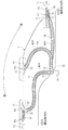
図1乃至図4に本発明の第1実施形態を示す。図1に示すように、車体10とスライドドア11との間にワイヤハーネスW/Hを架け渡し、車体10側に設けた支持部材12とスライドドア11側に設けた支持部材13とにワイヤハーネスW/Hを支持させている。スライドドア11側の支持部材13は、ボルト貫通穴13aにボルト(図示せず)を通して締結することによりスライドドア11側に固定し、車体10側の支持部材12も同様にボルト締結により車体10側に固定している。また、車体10とスライドドア11との間に架け渡されるワイヤハーネスW/Hの渡り部には、コルゲートチューブからなる外装材14を外装している。
Embodiments of the present invention will be described with reference to the drawings.
1 to 4 show a first embodiment of the present invention. As shown in FIG. 1, a wire harness W / H is bridged between a
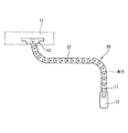
図2に示すように、スライドドア11側に設けた支持部材13の両側壁13bの内面にコイルバネ15を取り付けていると共に、該コイルバネ15に両側部16aを連結させたスライダー16を支持部材13に設けている。即ち、スライドドア11側の支持部材13は、スライダー16を左右方向の両側方向に移動可能に保持している。左右のコイルバネ15は、スライドドア11がオーバーストロークしたときのオーバーストローク量(本実施形態では20〜30mm程度)に相当する長さを伸縮できる同一のコイルバネを用いている。
As shown in FIG. 2, a
また、スライダー16は、外装材14の端部を嵌合保持してワイヤハーネスW/Hを挿通する回転部材17を水平方向に回転可能に支持している。本実施形態では、回転部材17の一端側17aの内周面に、外装材14であるコルゲートチューブの端部の凹凸と嵌合する環状の凹凸(図示せず)を設けていると共に、回転部材17の他端側17bの上面に、ワイヤハーネスW/Hを引き出すための筒部17cを上方に突出させ、下面にも前記上面側の筒部と対応する位置に筒部(図示せず)を下方に突出させて、前記上下に突出させた筒部17cを回転軸として機能させている。即ち、スライダー16の上下面に設けた上下の貫通穴16bに、上下に突出させた筒部17cをそれぞれ貫通させて該筒部17cを軸支することにより、スライダー16が回転部材17を水平方向へ回転可能に支持している。
In addition, the
また、スライダー16には、回転部材17から引き出されたワイヤハーネスW/Hをスライドドア11側に引き出すための引き出し通路16cを設けており、前記上方に突出させた回転部材17の筒部17cを、スライダー16に設けた引き出し通路16cに連続させることにより、回転部材17から引き出されたワイヤハーネスW/Hを、引き出し通路16cを経てスライドドア11側に引き出せるようにしている。
Further, the
一方、車体10側に設けた支持部材12には、前記のようなスライダーは設けず、支持部材12が回転部材17を直接支持する構造としている。
On the other hand, the
図1は、本実施形態において車体10とスライドドア11との間に架け渡されるワイヤハーネスW/Hの配索構造を示しており、図1のP1はスライドドア全閉位置、P3はスライドドア全開位置、P2はその中間位置における配索状態を示している。通常のスライドドアの開閉動作では、スライドドア11はスライドドア全閉位置P1から中間位置P2を通ってスライドドア全開位置P3に至る動作軌跡Tを描く。
FIG. 1 shows a wiring structure of a wire harness W / H that is bridged between a
一方、スライドドア全閉位置P1からスライドドア11を急開した場合には、スライドドア11は全開位置P3を20〜30mm程度通り越した位置P4までオーバーストロークした後、全開位置P3に戻る。図3(A)は全開位置P3におけるスライドドア側支持部材13の状態を示し、図3(B)はオーバーストローク位置P4におけるスライドドア側支持部材13の状態を示している。スライドドア11が全開位置P3を超えてP4までオーバーストロークする場合には、支持部材13内のスライダー16はワイヤハーネスW/Hの渡り部に引っ張られて、両側のコイルバネ15を伸縮させながらスライドドア11のオーバーストローク量だけオーバーストローク方向[図1において左方向(車両後方向)]と反対方向[図1において右方向(車両前方向)]にスライドする[図3(B)]。即ち、図1のように、支持部材13が所定量オーバーストロークして斜線を施したP4の位置に来ても、スライダー16は支持部材13内でオーバーストロークした分だけ反対側にスライドできるため、オーバーストローク位置P4でのスライダー16の位置は、車体10側から見ると、全開位置P3でのスライダー16の位置と同じ位置となる。
On the other hand, when the
また、スライドドア全開位置P3からスライドドア11を急閉した場合には、スライドドア11は全閉位置P1を20〜30mm程度通り越した位置P0までオーバーストロークした後、全閉位置P1に戻る。図4(A)は全閉位置P1におけるスライドドア側支持部材13の状態を示し、図4(B)はオーバーストローク位置P0におけるスライドドア側支持部材13の状態を示している。スライドドア11が全閉位置P1を超えてP0までオーバーストロークする場合には、支持部材13内のスライダー16はワイヤハーネスW/Hの渡り部に引っ張られて、両側のコイルバネ15を伸縮させながらスライドドア11のオーバーストローク量だけオーバーストローク方向[図1において右方向(車両前方向)]と反対方向[図1において左方向(車両後方向)]にスライドする[図4(B)]。即ち、図1のように、支持部材13が所定量オーバーストロークして斜線を施したP0の位置に来ても、スライダー16は支持部材13内でオーバーストロークした分だけ反対側にスライドできるため、オーバーストローク位置P0でのスライダー16の位置は、車体10側から見ると、全閉位置P1でのスライダー16の位置と同じ位置となる。
When the
したがって、ワイヤハーネスW/Hの渡り部はオーバーストロークのための余分な長さを加えることなく通常のスライドドア11の開閉動作に必要な長さのままで、スライドドア11のオーバーストロークにも対応することができるため、ワイヤハーネスW/Hの渡り部の弛みを防止し、見栄え良くすることができる。また、弛んだ渡り部を乗員が踏み付けることもないため、ワイヤハーネスW/Hの損傷も防止できる。
Therefore, the connecting portion of the wire harness W / H can be used for the overstroke of the
なお、オーバーストローク後は、スライドドア11が全開位置P3、全閉位置P1に戻ると共に、スライダー16も伸縮されたコイルバネ15の弾性力により、図3(A)、図4(A)に示すスライダー位置に戻される。
After the overstroke, the
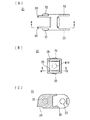
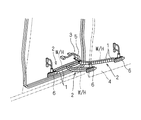
図5〜図7は第2実施形態を示している。第2実施形態では、図5に示すように、渡り配索されるワイヤハーネスW/Hの外装材20として、リンク部材21を所定角度回転可能に連結したキャタピラ状のケーブルガイドを用いている点以外は第1実施形態と同様としている。図6はケーブルガイド20を構成するリンク部材21を示し、図7はリンク部材21が連結された状態を示している。ケーブルガイド20を構成するリンク部材21は、図6(B)に示すように断面矩形の筒形状を有し、中空部分にワイヤハーネスW/Hを挿通する。リンク部材21の一端側には回転軸として機能する上下一対の凸部22を設けていると共に、他端側には連結する相手側リンク部材21の凸部22を軸支する上下一対の受け穴23を設けている。また、リンク部材21の一端側には上下一対の当接部24を設けていると共に、他端側には連結する相手側リンク部材21の当接部24に当接され相手側リンク部材21の回転角度を規制する上下一対の被当接部25を突出させている。
5 to 7 show a second embodiment. In 2nd Embodiment, as shown in FIG. 5, the caterpillar-shaped cable guide which connected the
第2実施形態においても、第1実施形態と同様、ワイヤハーネスW/Hの渡り部はオーバーストロークのための余分な長さを加えることなく通常のスライドドア11の開閉動作に必要な長さのままで、スライドドア11のオーバーストロークにも対応することができるため、ワイヤハーネスW/Hの渡り部の弛みを防止することができる。また、ワイヤハーネスW/Hに外装するケーブルガイド20の長さも必要最小限に抑えることができるため、重量化や高コスト化も抑制される。
Also in the second embodiment, as in the first embodiment, the connecting portion of the wire harness W / H has a length necessary for the normal opening / closing operation of the sliding
10 車体
11 スライドドア
12 車体側支持部材
13 スライドドア側支持部材
13a ボルト貫通穴
13b 両側壁
14、20 外装材
15 コイルバネ
16 スライダー
16a 両側部
16b 貫通穴
16c 引き出し通路
17 回転部材
17a 一端側
17b 他端側
17c 筒部
DESCRIPTION OF
Claims (3)
前記ワイヤハーネスを車体側に設けた支持部材とスライド部材側に設けた支持部材とで支持し、
前記スライド部材側には、前記ワイヤハーネスを挿通保持したスライダーを設け、該スライダーの両側を前記支持部材の両側壁の内面に設けたコイルバネに連結して両側方に移動可能に保持し、
前記スライド部材が所定のスライド完了位置からさらにオーバーストロークする場合には、前記スライダーが前記両側のコイルバネを伸縮させて前記スライド部材のオーバーストローク量だけオーバーストローク方向と反対方向にスライドし、
前記オーバーストローク後は、前記スライド部材が所定のスライド完了位置に戻ると共に、前記スライダーも前記伸縮されたコイルバネの弾性力によりオーバーストローク直前の元の位置に戻される構成としていることを特徴とするワイヤハーネスの配索構造。 A wiring harness wiring structure spanned between the vehicle body and the slide member,
The wire harness is supported by a support member provided on the vehicle body side and a support member provided on the slide member side,
Provided on the slide member side is a slider through which the wire harness is inserted and held, and both sides of the slider are connected to coil springs provided on the inner surfaces of both side walls of the support member so as to be movable on both sides.
When the slide member further overstrokes from a predetermined slide completion position, the slider slides in the opposite direction to the overstroke direction by the amount of overstroke of the slide member by expanding and contracting the coil springs on both sides,
After the overstroke, the slide member returns to a predetermined slide completion position, and the slider is also returned to the original position immediately before the overstroke by the elastic force of the expanded and contracted coil spring. Harness wiring structure.
前記スライダーは、前記外装材の端部を嵌合保持してワイヤハーネスを挿通する回転部材を水平方向に回転可能に支持していると共に、前記スライダーには、前記回転部材から引き出されたワイヤハーネスをスライド部材側に引き出すための引き出し通路を設けている請求項1に記載のワイヤハーネスの配索構造。 Covering the crossover portion of the wire harness with an exterior material,
The slider supports a rotating member that fits and holds the end portion of the exterior material and inserts the wire harness so as to be rotatable in the horizontal direction, and the slider has a wire harness drawn from the rotating member. The wiring structure of the wire harness according to claim 1, wherein a pull-out passage for pulling out the wire toward the slide member side is provided.
Priority Applications (1)
| Application Number | Priority Date | Filing Date | Title |
|---|---|---|---|
| JP2008312462A JP5077214B2 (en) | 2008-12-08 | 2008-12-08 | Wiring harness wiring structure for automobile |
Applications Claiming Priority (1)
| Application Number | Priority Date | Filing Date | Title |
|---|---|---|---|
| JP2008312462A JP5077214B2 (en) | 2008-12-08 | 2008-12-08 | Wiring harness wiring structure for automobile |
Publications (2)
| Publication Number | Publication Date |
|---|---|
| JP2010136593A true JP2010136593A (en) | 2010-06-17 |
| JP5077214B2 JP5077214B2 (en) | 2012-11-21 |
Family
ID=42347265
Family Applications (1)
| Application Number | Title | Priority Date | Filing Date |
|---|---|---|---|
| JP2008312462A Expired - Fee Related JP5077214B2 (en) | 2008-12-08 | 2008-12-08 | Wiring harness wiring structure for automobile |
Country Status (1)
| Country | Link |
|---|---|
| JP (1) | JP5077214B2 (en) |
Cited By (1)
| Publication number | Priority date | Publication date | Assignee | Title |
|---|---|---|---|---|
| JP2020083047A (en) * | 2018-11-26 | 2020-06-04 | 矢崎総業株式会社 | Power supply device |
Citations (7)
| Publication number | Priority date | Publication date | Assignee | Title |
|---|---|---|---|---|
| JPS6127425U (en) * | 1984-07-24 | 1986-02-19 | 古河電気工業株式会社 | Cable expansion and contraction device |
| JP2003306089A (en) * | 2002-04-11 | 2003-10-28 | Yazaki Corp | Cable extra length absorbing device and power supply device for slide door using the absorbing device |
| JP2006021689A (en) * | 2004-07-09 | 2006-01-26 | Furukawa Electric Co Ltd:The | Power feeding device for sliding door |
| JP2006327328A (en) * | 2005-05-24 | 2006-12-07 | Honda Motor Co Ltd | Harness routing structure |
| JP2007230495A (en) * | 2006-03-03 | 2007-09-13 | Fujikura Ltd | Power supply device |
| JP2008067563A (en) * | 2006-09-11 | 2008-03-21 | Yazaki Corp | Regular electric power supply device |
| JP2008195313A (en) * | 2007-02-15 | 2008-08-28 | Sumitomo Wiring Syst Ltd | Wire harness holder |
-
2008
- 2008-12-08 JP JP2008312462A patent/JP5077214B2/en not_active Expired - Fee Related
Patent Citations (7)
| Publication number | Priority date | Publication date | Assignee | Title |
|---|---|---|---|---|
| JPS6127425U (en) * | 1984-07-24 | 1986-02-19 | 古河電気工業株式会社 | Cable expansion and contraction device |
| JP2003306089A (en) * | 2002-04-11 | 2003-10-28 | Yazaki Corp | Cable extra length absorbing device and power supply device for slide door using the absorbing device |
| JP2006021689A (en) * | 2004-07-09 | 2006-01-26 | Furukawa Electric Co Ltd:The | Power feeding device for sliding door |
| JP2006327328A (en) * | 2005-05-24 | 2006-12-07 | Honda Motor Co Ltd | Harness routing structure |
| JP2007230495A (en) * | 2006-03-03 | 2007-09-13 | Fujikura Ltd | Power supply device |
| JP2008067563A (en) * | 2006-09-11 | 2008-03-21 | Yazaki Corp | Regular electric power supply device |
| JP2008195313A (en) * | 2007-02-15 | 2008-08-28 | Sumitomo Wiring Syst Ltd | Wire harness holder |
Cited By (1)
| Publication number | Priority date | Publication date | Assignee | Title |
|---|---|---|---|---|
| JP2020083047A (en) * | 2018-11-26 | 2020-06-04 | 矢崎総業株式会社 | Power supply device |
Also Published As
| Publication number | Publication date |
|---|---|
| JP5077214B2 (en) | 2012-11-21 |
Similar Documents
| Publication | Publication Date | Title |
|---|---|---|
| JP4746965B2 (en) | Power feeding device for slide structure | |
| JP4606275B2 (en) | Harness wiring structure using corrugated tube | |
| JP4999102B2 (en) | Power supply device for sliding door | |
| JP5012063B2 (en) | Wiring harness wiring structure for automobile | |
| JP5101981B2 (en) | Link harness wiring structure | |
| WO2011118063A1 (en) | Electricity-feeding wiring structure | |
| JP4952226B2 (en) | Wire harness wiring structure for doors | |
| JP6564813B2 (en) | Protective case for electric wire | |
| JP3850758B2 (en) | Slide door cable routing support structure | |
| JP2007276628A (en) | Wiring structure of wiring harness | |
| JP4256764B2 (en) | Harness guide protector, wire surplus length absorption structure including the same, and harness guide protector fixing method | |
| JP5077214B2 (en) | Wiring harness wiring structure for automobile | |
| JP2008038403A (en) | Power sliding door device for vehicle | |
| JP2011193687A (en) | Routing structure for power supply | |
| JP5424468B2 (en) | Wiring harness wiring structure | |
| JP2007181268A (en) | Power supply for slide structure | |
| JP5052032B2 (en) | Wiring harness wiring structure | |
| JP5264566B2 (en) | Wiring harness wiring structure | |
| JP4392304B2 (en) | Wire routing structure | |
| JP5434556B2 (en) | Wire harness support and conductive path device | |
| JP5203087B2 (en) | Link harness wiring structure | |
| JP5499579B2 (en) | Conductive pathway device for sliding doors | |
| JP2009213249A (en) | Routing structure for wire harness | |
| JP5264253B2 (en) | Wire harness wiring structure in vehicle seat | |
| WO2012127723A1 (en) | Door wiring device |
Legal Events
| Date | Code | Title | Description |
|---|---|---|---|
| A621 | Written request for application examination |
Free format text: JAPANESE INTERMEDIATE CODE: A621 Effective date: 20101209 |
|
| A977 | Report on retrieval |
Free format text: JAPANESE INTERMEDIATE CODE: A971007 Effective date: 20120515 |
|
| TRDD | Decision of grant or rejection written | ||
| A01 | Written decision to grant a patent or to grant a registration (utility model) |
Free format text: JAPANESE INTERMEDIATE CODE: A01 Effective date: 20120731 |
|
| A01 | Written decision to grant a patent or to grant a registration (utility model) |
Free format text: JAPANESE INTERMEDIATE CODE: A01 |
|
| A61 | First payment of annual fees (during grant procedure) |
Free format text: JAPANESE INTERMEDIATE CODE: A61 Effective date: 20120813 |
|
| FPAY | Renewal fee payment (prs date is renewal date of database) |
Free format text: PAYMENT UNTIL: 20150907 Year of fee payment: 3 |
|
| R150 | Certificate of patent (=grant) or registration of utility model |
Free format text: JAPANESE INTERMEDIATE CODE: R150 |
|
| LAPS | Cancellation because of no payment of annual fees |