JP2010132018A - Vehicle body front structure - Google Patents
Vehicle body front structure Download PDFInfo
- Publication number
- JP2010132018A JP2010132018A JP2008307210A JP2008307210A JP2010132018A JP 2010132018 A JP2010132018 A JP 2010132018A JP 2008307210 A JP2008307210 A JP 2008307210A JP 2008307210 A JP2008307210 A JP 2008307210A JP 2010132018 A JP2010132018 A JP 2010132018A
- Authority
- JP
- Japan
- Prior art keywords
- vehicle body
- crash box
- vehicle
- radiator support
- width direction
- Prior art date
- Legal status (The legal status is an assumption and is not a legal conclusion. Google has not performed a legal analysis and makes no representation as to the accuracy of the status listed.)
- Pending
Links
Images


Abstract
Description
本発明は車体前部構造に係り、特に、フロントサイドメンバの前端にクラッシュボックスを備えた自動車等の車両の車体前部構造に関する。 The present invention relates to a vehicle body front structure, and more particularly to a vehicle body front structure of a vehicle such as an automobile provided with a crash box at the front end of a front side member.
従来から、フロントサイドメンバの前端にクラッシュボックスを備えた自動車等の車両の車体前部構造が知られている(例えば、特許文献1参照)。この技術では、バンパレインフォースの両端部に、繊維強化樹脂製の荷重エネルギー吸収材がボルトとナットとによって締め付け結合されている。
しかしながら、この車体前部構造では、荷重エネルギー吸収材(クラッシュボックス)の前端部にラジエータサポートをボルト等で結合することがある。このような場合には、車両前面衝突時(全面衝突及びオフセット衝突)の早期に、ラジエータサポートがクラッシュボックスから離脱しないと、ラジエータサポートに邪魔されて、クラッシュボックスが意図する軸圧破壊(軸方向に作用する圧縮荷重による破壊)を行えず、クラッシュボックスのエネルギー吸収性能が低下する。 However, in this vehicle body front portion structure, a radiator support may be coupled to the front end portion of the load energy absorbing material (crash box) with a bolt or the like. In such a case, if the radiator support is not separated from the crash box at the early stage of the frontal collision of the vehicle (full collision and offset collision), it will be disturbed by the radiator support and the axial pressure destruction (axial direction) (Crash caused by compressive load acting on the crushing) cannot be performed, and the energy absorption performance of the crash box is reduced.
本発明は上記事実を考慮し、車両前面衝突時にラジエータサポートをクラッシュボックスから確実に離脱することができ、クラッシュボックスのエネルギー吸収性能を向上できる車体前部構造を提供することが目的である。 In consideration of the above-described facts, the present invention has an object to provide a vehicle body front structure that can reliably remove a radiator support from a crash box at the time of a vehicle frontal collision and improve the energy absorption performance of the crash box.
請求項1記載の本発明の車体前部構造は、車体前部の車幅方向両端下部に車体前後方向に沿って配設された左右一対のフロントサイドメンバと、該左右一対のフロントサイドメンバの前端に車体前後方向に沿って配設されると共に車両前面衝突時に車体前方側から順次破壊して衝突エネルギを吸収する左右一対のクラッシュボックスと、該左右一対のクラッシュボックスの前端より車体後方に設けられ、ラジエータを支持するラジエータサポートと、該ラジエータサポートと前記クラッシュボックスとを連結すると共に、前記クラッシュボックスとの結合位置が前記ラジエータサポートに対して車体前方側に設けられており、且つ、車両前面衝突時の前記クラッシュボックスの前端部の破壊によって前記クラッシュボックスとの結合が解除される連結手段と、を有する。 The vehicle body front structure according to the first aspect of the present invention includes a pair of left and right front side members disposed along the vehicle body longitudinal direction at the vehicle width direction lower ends of the vehicle body front portion, and the pair of left and right front side members. A pair of left and right crash boxes that are disposed along the vehicle front-rear direction at the front end and that sequentially breaks from the front side of the vehicle in the event of a vehicle frontal collision and absorbs collision energy, and are provided at the rear of the vehicle from the front ends of the pair of left and right crash boxes A radiator support that supports the radiator, the radiator support and the crash box are coupled to each other, a coupling position with the crash box is provided on the vehicle body front side with respect to the radiator support, and the front surface of the vehicle Breakage of the front end of the crash box at the time of a collision breaks the connection with the crash box. Has a coupling means that, a.
従って、ラジエータサポートとクラッシュボックスとを連結する連結手段におけるクラッシュボックスとの結合位置が、ラジエータサポートに対して車体前方側に設けられており、且つ、車両前面衝突時のクラッシュボックスの前端部の破壊によってクラッシュボックスと連結手段との結合が解除される。このため、車両前面衝突時の初期に、クラッシュボックスが車体前方側から順次破壊して衝突エネルギを吸収する際に、衝突体によってラジエータサポートが荷重を受けるより先に、クラッシュボックスの前端部の破壊によって、連結手段とクラッシュボックスとの結合が解除される。この結果、車両前面衝突時にラジエータサポートをクラッシュボックスから確実に離脱することができるので、クラッシュボックスはラジエータサポートの影響を受けずに安定した軸圧破壊を継続でき、クラッシュボックスのエネルギー吸収性能を向上できる。 Therefore, the coupling position of the crash box in the connecting means for coupling the radiator support and the crash box is provided on the front side of the vehicle body with respect to the radiator support, and the front end portion of the crash box at the time of a vehicle front collision is destroyed. As a result, the connection between the crash box and the connecting means is released. For this reason, when the crash box sequentially breaks from the front side of the vehicle body and absorbs the collision energy at the beginning of the frontal collision of the vehicle, the front end of the crash box is destroyed before the radiator support receives the load. Thus, the connection between the connecting means and the crash box is released. As a result, the radiator support can be reliably separated from the crash box in the event of a frontal collision of the vehicle, allowing the crash box to continue stable axial pressure failure without being affected by the radiator support, improving the energy absorption performance of the crash box. it can.
請求項2記載の本発明は、請求項1記載の車体前部構造において、前記連結手段は前記ラジエータサポートの一部に根元部を有し、該根元部から車体前方側へ突出形成された連結部であり、該連結部に設けられた前記クラッシュボックスとの結合位置が、前記連結部の根元部に対して車体前方側に設けられていることを特徴とする。 According to a second aspect of the present invention, in the vehicle body front portion structure according to the first aspect, the connection means has a root portion at a part of the radiator support, and is formed so as to protrude from the root portion toward the front side of the vehicle body. It is a part, The coupling | bonding position with the said crash box provided in this connection part is provided in the vehicle body front side with respect to the base part of the said connection part, It is characterized by the above-mentioned.
従って、連結手段を、ラジエータサポートの一部に根元部を有し、該根元部から車体前方側へ突出形成された連結部とし、連結部に設けられたクラッシュボックスとの結合位置を連結部の根元部に対して車体前方側に設けたため、連結手段を別部品として製造する必要がない。この結果、請求項1に記載の構成に比べて、部品点数を削減できると共に生産性も向上できる。 Therefore, the connecting means has a root portion at a part of the radiator support, and is a connecting portion formed to protrude from the root portion to the front side of the vehicle body, and the connecting position of the connecting portion with the crash box provided at the connecting portion is Since it is provided on the vehicle body front side with respect to the root portion, there is no need to manufacture the connecting means as a separate part. As a result, the number of parts can be reduced and productivity can be improved as compared with the configuration of the first aspect.
請求項1記載の本発明の車体前部構造は、車両前面衝突時にラジエータサポートをクラッシュボックスから確実に離脱することができ、クラッシュボックスのエネルギー吸収性能を向上できる。 The vehicle body front structure according to the first aspect of the present invention can reliably remove the radiator support from the crash box at the time of a vehicle front collision, and can improve the energy absorption performance of the crash box.
請求項2記載の本発明の車体前部構造は、部品点数を削減できると共に生産性も向上できる。 The vehicle body front part structure according to the second aspect of the present invention can reduce the number of parts and improve the productivity.
本発明における車体前部構造の第1実施形態を図1〜図3に従って説明する。 A first embodiment of a vehicle body front structure according to the present invention will be described with reference to FIGS.
なお、図中矢印UPは車体上方方向を示し、図中矢印FRは車体前方方向を示し、図中矢印INは車幅内側方向を示している。 In the figure, the arrow UP indicates the vehicle body upward direction, the arrow FR in the figure indicates the vehicle body front direction, and the arrow IN in the figure indicates the vehicle width inside direction.
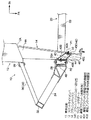
図2には本実施形態に係る車体前部構造が車体斜め前方から見た斜視図で示されており、図3には分解斜視図で示されている。また、図1には図2の1−1断面線に沿った拡大断面図が示されている。 FIG. 2 is a perspective view of the vehicle body front structure according to the present embodiment as viewed obliquely from the front of the vehicle body, and FIG. 3 is an exploded perspective view. FIG. 1 is an enlarged cross-sectional view taken along the line 1-1 in FIG.
図2に示されるように、本実施形態の車体前部10には、左右一対のフロントサイドメンバ12が、車幅方向両端下部に車体前後方向に沿って配設されている。また、これらのフロントサイドメンバ12は車体前後方向に沿って延在する閉断面構造とされている。
As shown in FIG. 2, a pair of left and right
左右一対の各フロントサイドメンバ12の車体前方側には、それぞれクラッシュボックス14が設けられており、これらのクラッシュボックス14は炭素繊維(CFRP)で構成されている。また、左右一対の各クラッシュボックス14は車体前後方向に沿って配設されており、後端部14Aが各フロントサイドメンバ12の前端面12Aに結合されている。また、各クラッシュボックス14の前端14Bには、図示を省略したバンパリインフォースメントの車幅方向外側部がそれぞれ固定されている。
一方、左右一対のクラッシュボックス14には、アルミ等の金属で構成されたラジエータサポート20が支持されており、このラジエータサポート20に図示を省略したラジエータが取付けられている。また、ラジエータサポート20は骨格部材として上横柱22と3分割された下横柱23、24、25を備えており、上横柱22と下横柱23、24、25とは、骨格部材としての5本の縦柱26、28、30、32、34によって互いに連結されている。
On the other hand, a
より具体的に説明すると、上横柱22の車幅方向中間部22Aと下横柱23はそれぞれ車幅方向に沿って配置されており、上横柱22の車幅方向両端部22B、22Cと下横柱24、25とがそれぞれ車幅方向内側前方から車幅方向外側後方へ向かって傾斜されている。また、上横柱22の車幅方向中間部22Aの車幅方向中央部と、下横柱23の車幅方向中央部とが縦柱26によって連結されており、上横柱22の車幅方向中間部22Aの車幅方向両端部と下横柱23の車幅方向両端部とが、縦柱28または縦柱30によって連結されている。さらに、上横柱22の車幅方向両端部22Bの車幅方向外側部と下横柱24の車幅方向外側部とが縦柱32によって連結されており、上横柱22の車幅方向両端部22Cの車幅方向外側部と下横柱25の車幅方向外側部とが縦柱34によって連結されている。このため、ラジエータサポート20は上横柱22、下横柱23、24、25と縦柱26、28、30、32、34とによって、梯子構造となっている。また、ラジエータサポート20の車幅方向外側端に位置する左右の縦柱32、34からは、それぞれ上下2本の横アーム36、38が、対応する各フロントサイドメンバ12の前端部12Bに向かって延設されており、横アーム36、38の車幅方向内側端部を互いに連結する縦アーム39が各フロントサイドメンバ12の前端部12Bにおける車幅方向外側の側壁に固定されている。
More specifically, the vehicle width direction
左右一対のクラッシュボックス14の各前端部14Cは、ラジエータサポート20における上横柱22、下横柱23と、縦柱26、28または縦柱26、30の間を通過しており、ラジエータサポート20より車体前方の位置まで達している。
Each
図3に示すように、左右一対のクラッシュボックス14における前端部14Cの上部には上取付部14Dが車体上方に向かって突出形成されており、前端部14Cの下部には下取付部14Eが車体下方に向かって突出形成されている。また、クラッシュボックス14の上取付部14Dと下取付部14Eとには、連結手段としての連結ブラケット40がそれぞれ設けられており、連結ブラケット40はアルミ等の金属で構成されている。
As shown in FIG. 3, an
図1(図1では車体右側のクラッシュボックスのみを示している)に示すように、連結ブラケット40は平面視形状が台形状となっており、各車幅方向内側壁部40Aがクラッシュボックス14の上取付部14Dまたは下取付部14Eにボルト等の締結手段42によって固定されている。一方、連結ブラケット40の各車幅方向外側壁部40Bは、縦柱28の車幅方向内側壁部28Aにボルト等の締結手段44によって固定されている。なお、連結ブラケット40の各車幅方向外側壁部40Bは、縦柱30の車幅方向内側壁部30Aにもボルト等の締結手段44によって固定されている。
As shown in FIG. 1 (only the crash box on the right side of the vehicle body is shown in FIG. 1), the connecting
また、連結ブラケット40の車幅方向内側壁部40Aは車幅方向外側壁部40Bに対して車体前方側へオフセットしている。このため、連結ブラケット40の車幅方向内側壁部40Aとクラッシュボックス14との結合位置(締結手段42の中心線)P1が、ラジエータサポート20に対して車体前方側に設けられており、結合位置P1が、車幅方向外側壁部40Bとラジエータサポート20との結合位置(締結手段44の中心線)P2に対して(P2より)車体前方側に設けられている。
Further, the vehicle width direction inner
従って、車両前面衝突時に左右一対のクラッシュボックス14が車体前方側から車体後方側に向かって順次軸圧破壊していくことで、衝突初期に上取付部14Dと下取付部14Eとが破壊するようになっている。この結果、連結ブラケット40とクラッシュボックス14との結合が解除されることで、車両前面衝突時にラジエータサポート20の骨格(縦柱28、30)自体が受ける入力荷重がクラッシュボックス14に加わらないようになっている。
Accordingly, the pair of left and
なお、連結ブラケット40における車幅方向内側壁部40Aの前端縁部と車幅方向外側壁部40Bの前端縁部とを連結する前壁部40Cは、車幅方向内側前方から車幅方向外側後方へ向かって傾斜しており、この前壁部40Cには、締結手段42を取付けるための作業孔46が形成されている。一方、連結ブラケット40における車幅方向内側壁部40Aの後端縁部と車幅方向外側壁部40Bの後端縁部とを連結する後壁部40Dは、車幅方向内側前方から車幅方向外側後方へ向かって傾斜している。また、縦柱28の車幅方向外側壁部28Bには、締結手段44を取付けるための作業孔48が形成されている。なお、縦柱30の車幅方向外側壁部30Bにも、締結手段44を取付けるための作業孔48が形成されている。
The
次に、本実施形態の作用を説明する。 Next, the operation of this embodiment will be described.
本実施形態では、図1に示すように、ラジエータサポート20とクラッシュボックス14とを連結する連結ブラケット40におけるクラッシュボックス14との結合位置P1が、連結ブラケット40におけるラジエータサポート20との結合位置P2に対して車体前方側に設けられており、且つ、車両前面衝突時、クラッシュボックス14の前端部の破壊によって、クラッシュボックス14における上取付部14Dと下取付部14Eとが破壊することで、クッション14と連結ブラケット40との結合が解除される。
In the present embodiment, as shown in FIG. 1, the coupling position P1 of the
このため、車両前面衝突時の初期に、クラッシュボックス14におけるラジエータサポート20より車体前方へ突出している部分は、ラジエータサポート20の影響を受けずに前方側から順次軸圧破壊して衝突エネルギを吸収する。また、衝突体によってラジエータサポート20が荷重を受けるより先に、クラッシュボックス14が車体前方側から順次軸圧破壊し前端部が破壊することで、クラッシュボックス14のラジエータサポート20との結合位置P2より車体前方側の部分が破壊する。このため、結合位置P2より車体前方側に設定されたクラッシュボックス14における上取付部14Dと下取付部14Eとが破壊する。この結果、結合位置P1におけるクラッシュボックス14と連結ブラケット40との結合が解除される。
For this reason, the portion of the
このように、本実施形態では、車両前面衝突時に、衝突体によってラジエータサポート20が荷重を受け、この荷重がクラッシュボックス14に影響を与えるより先に、ラジエータサポート20をクラッシュボックス14から確実に離脱させることができる。このため、クラッシュボックス14はラジエータサポート20より車体後方の部位においても、ラジエータサポート20より車体前方の部位と同様に、ラジエータサポート20の影響を受けずに安定した軸圧破壊を継続できるので、クラッシュボックス14のエネルギー吸収性能を向上できる。
As described above, in the present embodiment, the
なお、本実施形態において、連結ブラケット40をラジエータサポート20とクラッシュボックス14とにそれぞれ溶接等によって結合しても良く、この場合には、連結ブラケット40におけるクラッシュボックス14との結合面(結合位置)を、連結ブラケット40におけるラジエータサポート20との結合面(結合位置)に対して、車体前後方向に重ならない状態で車体前方側に設ける構成とする。
In the present embodiment, the
次に、本発明における車体前部構造の第2実施形態を図4に従って説明する。 Next, a second embodiment of the vehicle body front structure according to the present invention will be described with reference to FIG.
なお、第1実施形態と同一部材に付いては、同一符号を付してその説明を省略する。 In addition, about the same member as 1st Embodiment, the same code | symbol is attached | subjected and the description is abbreviate | omitted.
図4に示すように、本実施形態では、ラジエータサポート20における縦柱28の車幅方向内側部から車幅方向内側前方に向かって連結手段としての連結部60が突出形成されている。即ち、第1実施形態における連結ブラケット40に代えて、連結手段としての連結部60がラジエータサポート20の一部に突出形成されている。
As shown in FIG. 4, in the present embodiment, a connecting
連結部60は平面視形状が台形状に突出しており、車幅方向内側壁部60Aがクラッシュボックス14の上取付部14Dまたは下取付部14Eにボルト等の締結手段42によって固定されている。一方、連結部60はラジエータサポート20の縦柱28に根元部(車幅方向外側後端部)60Bを有している。また、連結部60の車幅方向内側壁部60Aは根元部60Bに対して車体前方側へオフセットしており、車幅方向内側壁部60Aとクラッシュボックス14との結合位置P1が、根元部60B(縦柱28の前壁部28C)に対して車体前方側に設けられている。
The
また、連結部60における車幅方向内側壁部60Aの前端縁部と根元部60Bの前端縁部とを連結する前壁部60Cは、車幅方向内側前方から車幅方向外側後方へ向かって傾斜しており、この前壁部60Cには、締結手段42を取付けるための作業孔46が形成されている。一方、連結部60における車幅方向内側壁部60Aの後端縁部と根元部60Bの後端縁部とを連結する後壁部60Dは、車幅方向内側前方から車幅方向外側後方へ向かって傾斜している。
Further, the
なお、ラジエータサポート20における縦柱30においても、車幅方向内側部から車幅方向内側前方に向かって連結手段としての連結部60が同様に突出形成されている。
In addition, also in the
従って、本実施形態においても第1実施形態と同様の作用効果が得られる。さらに、本実施形態では、連結手段を別部品(第1実施形態の連結ブラケット40)として製造する必要がない。この結果、本実施形態は第1実施形態に比べて部品点数を削減できると共に生産性も向上できる。
Therefore, also in this embodiment, the same effect as the first embodiment can be obtained. Furthermore, in this embodiment, it is not necessary to manufacture the connection means as a separate part (the
以上に於いては、本発明を特定の実施形態について詳細に説明したが、本発明はかかる実施形態に限定されるものではなく、本発明の範囲内にて他の種々の実施形態が可能であることは当業者にとって明らかである。例えば、本発明における連結手段は前記各実施形態に限定されず、ラジエータサポート20とクラッシュボックス14とを連結すると共に、クラッシュボックス14との結合位置がラジエータサポート20に対して車体前方側に設けられており、且つ、車両前面衝突時のクラッシュボックス14の前端部の破壊によってクラッシュボックス14との結合が解除される構成であれば、他の連結手段であってもよい。
Although the present invention has been described in detail with respect to specific embodiments, the present invention is not limited to such embodiments, and various other embodiments are possible within the scope of the present invention. It will be apparent to those skilled in the art. For example, the connecting means in the present invention is not limited to the above-described embodiments, and connects the
また、本発明におけるラジエータサポート20は前記各実施形態のように、横柱22、24と縦柱26、28、30、32、34とを備えた梯子構造に限定されず、他の構造にしてもよい。
Further, the
また、本発明の車体前部構造を適用する車両におけるフロントサイドメンバ、クラッシュボックスの各形状は上記各実施形態に限定されない。 Further, the shapes of the front side member and the crash box in the vehicle to which the vehicle body front structure of the present invention is applied are not limited to the above embodiments.
また、本発明の車体前部構造を適用する車両におけるクラッシュボックス、ラジエータサポートの各材質は上記各実施形態に限定されない。 Moreover, each material of the crash box and the radiator support in the vehicle to which the vehicle body front structure of the present invention is applied is not limited to the above embodiments.
10 車体前部
12 フロントサイドメンバ
14 クラッシュボックス
14C クラッシュボックスの上取付部
14D クラッシュボックスの下取付部
20 ラジエータサポート
40 連結ブラケット(連結手段)
40B 連結ブラケットの車幅方向外側壁部
40A 連結ブラケットの車幅方向内側壁部
60 ラジエータサポートの連結部(連結手段)
60A ラジエータサポートの連結部の車幅方向内側壁部
60B ラジエータサポートの連結部の根元部
DESCRIPTION OF
40B Vehicle bracket direction outer wall portion of connecting
60A Inner side wall in the vehicle width direction of the connecting portion of the radiator support 60B Root portion of the connecting portion of the radiator support
Claims (2)
該左右一対のフロントサイドメンバの前端に車体前後方向に沿って配設されると共に車両前面衝突時に車体前方側から順次破壊して衝突エネルギを吸収する左右一対のクラッシュボックスと、
該左右一対のクラッシュボックスの前端より車体後方に設けられ、ラジエータを支持するラジエータサポートと、
該ラジエータサポートと前記クラッシュボックスとを連結すると共に、前記クラッシュボックスとの結合位置が前記ラジエータサポートに対して車体前方側に設けられており、且つ、車両前面衝突時の前記クラッシュボックスの前端部の破壊によって前記クラッシュボックスとの結合が解除される連結手段と、
を有する車体前部構造。 A pair of left and right front side members disposed along the longitudinal direction of the vehicle body at both lower ends in the vehicle width direction of the front portion of the vehicle body;
A pair of left and right crash boxes that are disposed along the front-rear direction of the vehicle body at the front ends of the pair of left and right front side members and absorb the collision energy by sequentially breaking from the front side of the vehicle body at the time of a vehicle front collision;
A radiator support that is provided at the rear of the vehicle body from the front ends of the pair of left and right crash boxes and supports the radiator;
The radiator support and the crash box are connected to each other, and the coupling position with the crash box is provided on the vehicle body front side with respect to the radiator support, and the front end portion of the crash box at the time of a vehicle front collision A connecting means for releasing the connection with the crash box by destruction;
A vehicle body front structure.
Priority Applications (1)
| Application Number | Priority Date | Filing Date | Title |
|---|---|---|---|
| JP2008307210A JP2010132018A (en) | 2008-12-02 | 2008-12-02 | Vehicle body front structure |
Applications Claiming Priority (1)
| Application Number | Priority Date | Filing Date | Title |
|---|---|---|---|
| JP2008307210A JP2010132018A (en) | 2008-12-02 | 2008-12-02 | Vehicle body front structure |
Publications (1)
| Publication Number | Publication Date |
|---|---|
| JP2010132018A true JP2010132018A (en) | 2010-06-17 |
Family
ID=42343808
Family Applications (1)
| Application Number | Title | Priority Date | Filing Date |
|---|---|---|---|
| JP2008307210A Pending JP2010132018A (en) | 2008-12-02 | 2008-12-02 | Vehicle body front structure |
Country Status (1)
| Country | Link |
|---|---|
| JP (1) | JP2010132018A (en) |
Cited By (3)
| Publication number | Priority date | Publication date | Assignee | Title |
|---|---|---|---|---|
| US9550463B2 (en) | 2012-12-07 | 2017-01-24 | Toyota Jidosha Kabushiki Kaisha | Vehicle body end section structure |
| US9555754B2 (en) | 2013-01-18 | 2017-01-31 | Toyota Jidosha Kabushiki Kaisha | Vehicle body front portion structure |
| CN113825877A (en) * | 2019-05-15 | 2021-12-21 | 三一公路产品有限公司 | Crash attenuator with release plate hinge assembly, release plate hinge assembly and method of use thereof |
-
2008
- 2008-12-02 JP JP2008307210A patent/JP2010132018A/en active Pending
Cited By (3)
| Publication number | Priority date | Publication date | Assignee | Title |
|---|---|---|---|---|
| US9550463B2 (en) | 2012-12-07 | 2017-01-24 | Toyota Jidosha Kabushiki Kaisha | Vehicle body end section structure |
| US9555754B2 (en) | 2013-01-18 | 2017-01-31 | Toyota Jidosha Kabushiki Kaisha | Vehicle body front portion structure |
| CN113825877A (en) * | 2019-05-15 | 2021-12-21 | 三一公路产品有限公司 | Crash attenuator with release plate hinge assembly, release plate hinge assembly and method of use thereof |
Similar Documents
| Publication | Publication Date | Title |
|---|---|---|
| JP6459839B2 (en) | Vehicle skeleton structure | |
| JP5557925B2 (en) | Body structure | |
| JP6227681B2 (en) | Body structure | |
| JP5522118B2 (en) | Motor mounting structure | |
| JP5736943B2 (en) | Vehicle front structure | |
| JP6299701B2 (en) | Vehicle lower structure | |
| JP6187447B2 (en) | Vehicle front structure | |
| JP2009051440A (en) | Vehicle body front part structure | |
| JP2007038839A (en) | Rear part car body structure for vehicle | |
| JP2010006102A (en) | Vehicle skeleton structure | |
| JP6686006B2 (en) | Front body structure of vehicle | |
| JP4231473B2 (en) | Steering gear box mounting structure | |
| JP2006015859A (en) | Front vehicle body structure of vehicle | |
| JP2010064667A (en) | Vehicle sub-frame structure | |
| JP5975045B2 (en) | Vehicle lower structure | |
| EP2572941B1 (en) | Crush box and vehicle bumper apparatus including the same | |
| JP2010132018A (en) | Vehicle body front structure | |
| JP6264349B2 (en) | Vehicle front structure | |
| JP2005153800A (en) | Front part vehicle body structure for vehicle | |
| JP2007055340A (en) | Impact force absorbing structure of body front part of automobile | |
| JP2006137374A (en) | Front body structure of vehicle | |
| JP2007131150A (en) | Front bumper structure of vehicle | |
| JP5723562B2 (en) | Auto body front structure | |
| JP2009120012A (en) | Vehicle front body structure | |
| JP2003312542A (en) | Front vehicle body structure |